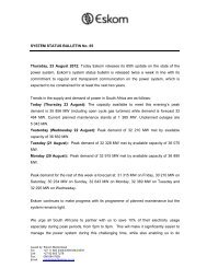
GCCA-2016 - Eskom
GCCA-2016 - Eskom
GCCA-2016 - Eskom

Create successful ePaper yourself
Turn your PDF publications into a flip-book with our unique Google optimized e-Paper software.
May 2013<br />
Generation Connection<br />
Capacity Assessment of<br />
the <strong>2016</strong> Transmission<br />
Network (<strong>GCCA</strong>-<strong>2016</strong>)
i<br />
Disclaimer<br />
The publication of the Generation Connection<br />
Capacity Assessment of <strong>2016</strong> Transmission<br />
Network (<strong>GCCA</strong>-<strong>2016</strong>) is to inform stakeholders<br />
of the potential capacity available on the <strong>Eskom</strong><br />
Transmission Network to facilitate connection of<br />
generation projects. The Generation Connection<br />
Capacity Assessment is based on the information<br />
currently available and is subject to change.<br />
The information contained in this document does not<br />
constitute advice. It is a guideline to assist stakeholders.<br />
<strong>Eskom</strong> Holdings SOC Limited makes no representations<br />
regarding the suitability of the information to be used<br />
for any other purpose. All information is provided<br />
“AS IS” without warranty of any kind and is subject<br />
to change without notice. The entire risk arising out<br />
of its use remains with the recipient. In no event<br />
shall <strong>Eskom</strong> Holdings SOC Limited be liable for any<br />
direct, consequential, incidental, special, punitive, or<br />
any other damages whatsoever.<br />
Generation Connection Capacity Assessment<br />
While the Generation Connection Assessment of<br />
<strong>2016</strong> Transmission Network (<strong>GCCA</strong>-<strong>2016</strong>) will be<br />
updated periodically, <strong>Eskom</strong> Holdings SOC Limited makes<br />
no representation or warranty as to the accuracy,<br />
reliability, validity, or completeness of the information<br />
in this document.<br />
<strong>Eskom</strong> does however endeavour to release the<br />
Generation Connection Capacity Assessment<br />
based on its best available information at its<br />
disposal at all times to ensure that the stakeholders<br />
are kept informed about the developments in<br />
the transmission network. Thus, the information<br />
contained in this document represents the most<br />
up-to-date information that was available at the time<br />
it was released.
Executive Summary<br />
The Intergraded Resource Plan (IRP 2010-2030)<br />
has allocated 17 800 MW of solar and wind<br />
generation projects in line with the Government’s<br />
commitment to reducing emissions. One of<br />
the challenges for the integration of renewable<br />
energy (RE) generation has always been the cost<br />
of integration and the time-lines for creating grid<br />
capacity to accommodate RE generation, therefore<br />
the location of the RE plants in relation to the grid<br />
is very important. However, the proximity of the<br />
plant on its own is not sufficient if the grid does not<br />
have the capacity to connect the RE generated. This<br />
study was commissioned to determine the grid’s<br />
capacity to connect all types of generation plant at<br />
high-voltage (HV) busbars of the Main Transmission<br />
System (MTS) substations in <strong>2016</strong>. Although most<br />
RE connections will be at Distribution level, the lack<br />
of capacity in the Transmission network may delay<br />
the connection of new generation.<br />
A previous study was done to determine the 2012<br />
connection capacity of the Transmission grid, where<br />
the study focused on the Eastern Cape, Western<br />
Cape and Northern Cape. This <strong>2016</strong> study was<br />
extended to include all MTS substations in the<br />
country. Studies on both steady-state and transient<br />
stability limits were conducted to determine the<br />
grid’s connection capacity. Stability limits are typically<br />
important when considering the integration of<br />
multiple RE generation sources in an area, but for<br />
individual applications the steady-state limit could<br />
be sufficient.<br />
MTS substations supply specific geographic areas, and<br />
this fact was taken into account when considering<br />
the connection capacity, based on the assumption<br />
that RE plants in a supply area will probably be<br />
connected to the MTS substation supplying that<br />
area. The MTS is divided into 27 supply areas<br />
located in all 9 provinces.<br />
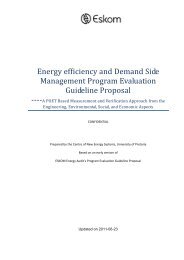
The geographic location of the supply areas and<br />
their generation connection capacity, indicating<br />
both the steady-state N-1 limit and the stability<br />
limit, are shown in Figure A.<br />
The generation connection capacities in Figure A<br />
indicate what capacity the Transmission grid can<br />
connect without violating the Grid Code’s technical<br />
criteria for generation integration. The Grid Code<br />
states that the National Transmission Company<br />
(NTC) shall provide quotations for connection. The<br />
grid connection capacity will provide a guideline for<br />
the generation capacity that the grid can connect<br />
for Independent Power Producers (IPPs) and for<br />
<strong>Eskom</strong>. This study will also assist the NTC with<br />
determining the requirements for the new capacity<br />
that should be created in certain areas to cater for<br />
the applications received from IPPs.<br />
The results indicate that the grid has the capacity<br />
to connect high levels of RE generation, provided<br />
that the RE points are spread around the country.<br />
Although the grid appears to have enough capacity<br />
to integrate all the IRP requirements, care will<br />
have to be taken to ensure that, at a local level<br />
where IPP applications are concentrated in certain<br />
areas, the grid will have enough capacity, while<br />
highlighting areas with available grid capacity to<br />
connect with IPPs.<br />
Stability limits for large-area integration indicate<br />
that Limpopo and North West combined will be<br />
transiently stable for 10 GW of new generation, the<br />
entire KwaZulu-Natal area can connect 17 GW, and<br />
the Cape area (Northern, Southern and Western)<br />
will be stable for 15 GW.<br />
<strong>GCCA</strong>-<strong>2016</strong> © <strong>Eskom</strong> 2013 ii
iii<br />
Figure A: Generation Connection Capacities (steady-state/stability) for the <strong>2016</strong> Grid<br />
List of abbreviations<br />
CSP Concentrating Solar Power<br />
DoE Department of Energy (Government of South Africa)<br />
<strong>GCCA</strong> Grid Connection Capacity Assessment<br />
HV busbar High Voltage busbar of a substation (> 132 kV at Transmission level)<br />
IPP Independent Power Producer<br />
LV busbar Low Voltage busbar of a substation (
Contents<br />
Executive Summary ii<br />
1 Introduction 1<br />
1.1 Context of the Generation Connection Capacity 1<br />
1.2 Structure of the document 1<br />
2 Background 2<br />
3 Methodology and Interpretation 3<br />
3.1 Methodology of calculation 3<br />
3.2 Interpretation of the connection capacity value 4<br />
4 Definition of Transmission Connection Capacity 5<br />
5 Supply Areas by Province: Connection Capacity 6<br />
5.1 Eastern Cape 7<br />
5.2 Free State 8<br />
5.3 Gauteng 9<br />
5.4 KwaZulu-Natal 10<br />
5.5 Limpopo 11<br />
5.6 Mpumalanga 12<br />
5.7 North West Province 13<br />
5.8 Northern Cape 14<br />
5.9 Western Cape 15<br />
6 Generation Connection Capacity by Supply Area 16<br />
6.1 Bloemfontein area 16<br />
6.2 Carltonville area 17<br />
6.3 East London Bisho area 17<br />
<strong>GCCA</strong>-<strong>2016</strong> © <strong>Eskom</strong> 2013 iv
v<br />
6.4 Empangeni area 17<br />
6.5 Highveld North area 17<br />
6.6 Highveld South area 17<br />
6.7 Johannesburg area 18<br />
6.8 Karoo area 18<br />
6.9 Kimberly area 18<br />
6.10 Ladysmith area 18<br />
6.11 Lowveld area 19<br />
6.12 Namaqualand area 19<br />
6.13 Newcastle area 19<br />
6.14 Nigel area 19<br />
6.15 Peninsula area 20<br />
6.16 Pinetown area 20<br />
6.17 Polokwane area 20<br />
6.18 Port Elizabeth area 20<br />
6.19 Pretoria area 21<br />
6.20 Rustenburg area 21<br />
6.21 Southern Cape area 21<br />
6.22 Vaal Triangle area 21<br />
6.23 Warmbad area 22<br />
6.24 Waterberg area 22<br />
6.25 Welkom area 22<br />
6.26 West Coast area 22<br />
6.27 West Rand area 22<br />
6.28 Large-Area Integration Stability limits 23<br />
7 High-Level Connection Estimates 24<br />
Appendix A: Renewable Energy IPPs - Round 1 and 2 Preferred Bidders 24<br />
Generation Connection Capacity Assessment
1 Introduction<br />
1.1 Context of the Generation Connection Capacity<br />
<strong>Eskom</strong> is the biggest producer of electricity in South<br />
Africa; it is also the sole transmitter of electricity via<br />
a transmission network which supplies electricity<br />
at high voltages to a number of key customers<br />
and distributors. <strong>Eskom</strong> is a vertically integrated<br />
company licensed to generate, transmit and<br />
distribute electricity. The transmission licence is held<br />
by <strong>Eskom</strong> Transmission, the transmission network<br />
service provider (TNSP). Planning the transmission<br />
network is the responsibility of the Grid Planning<br />
Department in the Transmission Division.<br />
The intention of this document is to provide<br />
an indication of the available capacity for the<br />
connection of new generation at the Main<br />
Transmission System (MTS) substations on the<br />
<strong>Eskom</strong> transmission network that will be in service<br />
by <strong>2016</strong>. The capacity specifies the substation<br />
limit as well as the transmission backbone limit<br />
for simultaneous generation connection at an<br />
HV busbar of an MTS substation in a specific<br />
area. The grid is divided into 27 load supply areas,<br />
and these supply areas are used as generation<br />
connection areas to assess how much generation<br />
can be connected in each area. The capacities<br />
specified are for both steady-state and transient<br />
power system conditions. The transient stability<br />
limit represents the technically feasible integration<br />
limit, especially with regard to area limits. The<br />
provided values are not intended to be fixed<br />
specific connection capacities as each connection<br />
is unique, but rather to be used as a guideline to<br />
indicate the potential for connecting to a specific<br />
point or area in the transmission network, and also<br />
to identify the network strengthening required<br />
to unlock the network capacity to integrate<br />
more IPPs in areas which have high generation<br />
resources available.<br />
The steady-state results provide the available<br />
capacity at MTS substations and also at an area level.<br />
All areas in the Cape have been combined to test<br />
the capacity of the Cape corridor. In the transient<br />
study, the focus of the results is on area limits, and<br />
the corridors supplying a number of areas are also<br />
tested by combining a number of areas into one<br />
large area. The results of this study can be used to<br />
assess the capacity (MW) that can be connected at<br />
each MTS substation for N-1 Grid Code reliability<br />
level, and also the total capacity that an area or<br />
a group of areas can handle without violating the<br />
limits of network stability.<br />
1.2 Structure of the document<br />
The document is structured as follows:<br />
Chapter 2 provides the background to the study<br />
and the scope of the study.<br />
Chapter 3 outlines the methodology employed<br />
in the study and how the results should<br />
be interpreted.<br />
Chapter 4 gives the definition of the generation<br />
connection capacity and typical layouts<br />
of how new plants can be connected<br />
to the MTS substation.<br />
Chapter 5 gives the generation connection capacity<br />
of supply areas on a provincial basis.<br />
Chapter 6 provides the generation connection<br />
capacity at MTS substations per<br />
supply area, giving both the steadystate<br />
(N-1) and the stability capacity.<br />
The steady-state limit is given per<br />
MTS substation HV busbar, and the<br />
stability limit is given per area.<br />
Chapter 7 explains a process which could be followed<br />
to obtain high-level cost estimations<br />
for generation integration.<br />
<strong>GCCA</strong>-<strong>2016</strong> © <strong>Eskom</strong> 2013 1
2<br />
2 Background<br />
<strong>Eskom</strong> released the document on Generation<br />
Connection Capacity Assessment for the 2012<br />
Transmission Grid (<strong>GCCA</strong>-2012) early in 2011 in<br />
response to the Government’s REBID programme<br />
and the large number of renewable generation<br />
applications and enquiries received by <strong>Eskom</strong>.<br />
This document only covered the Cape provinces<br />
because of time constraints and the prioritisation<br />
of the locations where enquiries were made.<br />
The <strong>GCCA</strong>-2012 focused on the connection<br />
at the Lower Voltage (LV) busbars of the Main<br />
Transmission System (MTS) substations and took<br />
into account the limitation of the transformers, as<br />
the emphasis was on connecting to the existing<br />
transmission infrastructure.<br />
This version of the <strong>GCCA</strong> document not only<br />
considers the Transmission Grid that is expected to<br />
be in place by <strong>2016</strong>, but now also includes the entire<br />
country. The focus is now on the generation that<br />
can be connected to the High Voltage (HV) busbar<br />
Generation Connection Capacity Assessment<br />
at the MTS substation without the limitations of<br />
the transformers, i.e. on what can be first absorbed<br />
for supplying the local MTS supply area and what in<br />
addition can be transported into the Transmission<br />
Grid to supply more distant loads. The requirement<br />
is that the Transmission grid should still meet the<br />
single condition (N-1) criteria of the Grid Code.<br />
The Transmission Grid is divided into 27<br />
Transmission supply areas which contain a number<br />
of MTS substations to supply the demand in the area.<br />
These supply areas are grouped into the 9 provinces<br />
of the country. The supply areas have been analysed<br />
to determine the generation connection capacities<br />
of the MTS substations within each supply area.<br />
An overview of each province and the provinces’<br />
supply areas is given in Section 5. An alphabetical list<br />
of MTS substations and their connection capacities<br />
per supply area is provided in Chapter 6.
3 Methodology and Interpretation<br />
This chapter explains how the generation connection<br />
capacities were calculated for the MTS substations<br />
and how this value can be interpreted.<br />
3.1 Methodology of calculation<br />
Connection capacity is determined by the available<br />
Transmission infrastructure in service to which a<br />
proposed generation project can connect and then<br />
transport the generated power to the loads. The<br />
document considers the connection capacity that<br />
will be available on the Transmission grid for the<br />
year <strong>2016</strong>, taking into account the Transmission<br />
infrastructure that is expected to be in service<br />
in <strong>2016</strong>, based on the approved Transmission<br />
Development Plan for the period 2013 to 2022.<br />
The Distribution infrastructure is not considered<br />
in this document because of the sheer volume of<br />
infrastructure and the rapid changes that can be<br />
implemented at the lower voltages. All generation<br />
integration requirements will have to be considered<br />
at a local level and the direct connections can in<br />
general be implemented relatively quickly. The real<br />
issue that this document addresses is how much<br />
generation can be integrated and transported to the<br />
point where it is required at the Transmission level.<br />
The Transmission Connection Capacity provides<br />
the overall capacity that can be absorbed at a<br />
specific MTS connection point without requiring<br />
any reinforcement, either directly connected to<br />
the MTS substation or via the distribution network<br />
supplied by the MTS substation. In other words,<br />
it is the indicative capacity for connecting new<br />
generation within the geographical supply area of<br />
that particular MTS substation.<br />
Certain assumptions were made regarding the<br />
potential allocation of the downstream load in<br />
order to determine the connection capacity at the<br />
MTS substations. Essentially, the new generation will<br />
first supply the local load within the supply area<br />
of the MTS substation and send the excess into<br />
the Transmission network via the MTS substation<br />
transformers and connecting Transmission lines.<br />
The difference between the previous <strong>GCCA</strong><br />
document, <strong>GCCA</strong>-2012, and this one, <strong>GCCA</strong>-<strong>2016</strong>,<br />
is that in this case the amount of generation is<br />
considered to be modelled at the High-Voltage<br />
busbar of the substation, i.e. the 400-kV, 275-kV<br />
or 220-kV busbar. The generation value at the<br />
HV busbar was increased until the Grid Code<br />
criteria were breached for single contingency(N-1)<br />
conditions on the Transmission level grid. This value<br />
determined the individual generation limit at the<br />
MTS substation.<br />
The MTS substation is connected within a<br />
Transmission load supply area system, however,<br />
in total there are 27 such areas, and the limit<br />
of the supply area dictates the potential limit at<br />
the individual MTS substation. The limit at each<br />
MTS substation within a supply area provides an<br />
indication of the proportional allocation of the<br />
supply area limit to the substations. The studies<br />
are then rerun, increasing the generation of the<br />
supply area with each substation at their relative<br />
proportional contribution until the area’s N-1 limit<br />
is reached. This is then the generation connection<br />
capacity value for each MTS substation in the<br />
supply area.<br />
The capacities are determined for both steadystate<br />
and transient power system conditions. In<br />
effect, the transient stability limit represents the<br />
technically feasible integration limit with regard to<br />
area limits.<br />
<strong>GCCA</strong>-<strong>2016</strong> © <strong>Eskom</strong> 2013 3
4<br />
3.2 Interpretation of the connection<br />
capacity value<br />
Based on the connection capacity of a specific<br />
MTS substation, a developer is able to make a high<br />
level assessment of what is likely to be required to<br />
connect his/her generation project to this point on<br />
the <strong>Eskom</strong> Transmission network.<br />
This would be done by first identifying in which<br />
MTS substation supply area the generation project<br />
will be located and relating it to the approximate<br />
distance to that MTS substation or the nearest<br />
Distribution substation within that supply area. The<br />
maps indicating the supply areas are provided by<br />
province in Chapter 6 of this document.<br />
Generation Connection Capacity Assessment<br />
Using the proposed total MW output of the<br />
generation plant, the connection requirements and<br />
timing assessment can be done as follows:<br />
Project MW output less than MTS<br />
connection capacity<br />
The generation project should be able to connect<br />
to the Transmission network without requiring<br />
any additional deep transformation reinforcement.<br />
Only shallow connection works should be required,<br />
either via the distribution network or by connecting<br />
directly to the HV or LV busbar of the MTS substation.<br />
Project MW output is around MTS<br />
connection capacity<br />
If the MW output of the generation project is of<br />
the same order as the MTS substation’s connection<br />
capacity, around a ± 10% variation, then it may be<br />
possible to connect the project without requiring<br />
any additional deep reinforcement and only shallow<br />
connection works will be required.<br />
Project MW output greater than MTS<br />
connection capacity<br />
The generation project will not be able to connect<br />
without requiring some form of additional deep<br />
Transmission reinforcement (e.g. Transmission line,<br />
transformer) in addition to the shallow connection<br />
works. The deep reinforcement is likely to place a<br />
time constraint on connecting the generation plant<br />
project, depending on the nature and size of the<br />
transmission reinforcement works required.
4 Definition of Transmission Connection Capacity<br />
A “Transmission Connection” is defined for the<br />
purposes of this document as the direct or indirect<br />
connection to an MTS substation at either the LV<br />
or the HV busbar.<br />
A direct connection at the HV busbar would<br />
require the construction of a Transmission voltage<br />
level line (400 kV, 275 kV or 220 kV) from the<br />
generation plant directly to the MTS substation.<br />
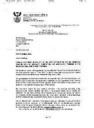
The connection to the MTS substation’s LV busbar<br />
can be made in number of ways, namely:<br />
Gen<br />
Plant<br />
Direct Connection<br />
to an MTS Substation<br />
400 kV (HV)<br />
132 kV (LV)<br />
Loop-in Connection to an<br />
existing transmission line<br />
Figure 4.1: Generation plant connection to the LV busbar options<br />
• Direct connection from the generation plant<br />
substation to the MTS substation via a dedicated<br />
transmission line.<br />
• Looping in an existing distribution line which<br />
is connected to the MTS substation into the<br />
generation plant substation.<br />
• Direct connection from the generation plant’s<br />
substation to a Distribution substation which is<br />
supplied by the MTS substation.<br />
The 3 LV busbar connection options are shown<br />
diagrammatically in Figure 4.1.<br />
132 kV (LV)<br />
22 kV (LV)<br />
Distribution Substation<br />
Gen<br />
Plant<br />
MTS Substation<br />
Gen<br />
Plant<br />
132 kV (LV)<br />
22 kV (LV)<br />
Distribution Substation<br />
Direct Connection to a<br />
Distribution Substation<br />
<strong>GCCA</strong>-<strong>2016</strong> © <strong>Eskom</strong> 2013 5
6<br />
5 Supply Areas by Province: Connection Capacity<br />
The Grid is divided into 27 supply areas that are<br />
used for conducting the load forecast, and these<br />
areas have a certain number of MTS substations<br />
supplied by them. The supply areas do cross the<br />
provincial boundaries in some cases because these<br />
areas are related to the networks from which they<br />
are supplied.<br />
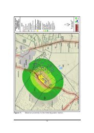
Figure 5 Main Transmission System with supply areas<br />
Generation Connection Capacity Assessment<br />
Figure 5 displays the grid layout with all supply<br />
areas, and provincial maps with the associated<br />
supply areas are shown in Figures 5.1 to 5.9 in<br />
alphabetical order.<br />
The provincial maps give two figures for each supply<br />
area, which represent the steady-state limit in MW<br />
and the stability limit in MW for that particular<br />
supply area.
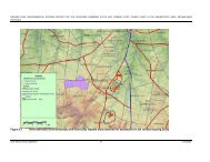
5.1 Eastern Cape<br />
The Eastern Cape Province has two complete supply<br />
areas and one that overlaps from the Northern<br />
Cape. The complete supply areas are Port Elizabeth<br />
and East London.<br />
The overlapping supply area is the Karoo. The<br />
MTS substations at their generation connection<br />
capacities are listed alphabetically by supply area in<br />
Chapter 6.<br />
Figure 5.1 Eastern Cape Province with generation connection capacity limit (steady-state limit MW / Stability limit MW)<br />
<strong>GCCA</strong>-<strong>2016</strong> © <strong>Eskom</strong> 2013 7
8<br />
5.2 Free State<br />
The Free State Province has two complete supply<br />
areas and several overlapping supply areas, namely<br />
two from the Northern Cape, one from the North<br />
West Province, one from Gauteng and one from<br />
KwaZulu-Natal. The complete supply areas are<br />
Bloemfontein and Welkom. The overlapping supply<br />
areas are Kimberley, Karoo, Carltonville, Vaal Triangle<br />
and Tugela.<br />
The MTS substations at their generation connection<br />
capacities are listed alphabetically by supply area in<br />
Chapter 6.<br />
Please note that the Serumula substation is only a<br />
series capacitor switching station.<br />
Figure 5.2 Free State Province with generation connection capacity limit (steady-state limit MW / Stability limit MW)<br />
Generation Connection Capacity Assessment
5.3 Gauteng<br />
Gauteng Province has five complete supply areas<br />
and two that overlap from the Limpopo and North<br />
West Province.<br />
The complete supply areas are Johannesburg, Nigel,<br />
Pretoria, West Rand and Vaal Triangle. The overlapping<br />
supply areas are Warmbad and Carletonville.<br />
The MTS substations at their generation connection<br />
capacities are listed alphabetically by supply area in<br />
Chapter 6.<br />
Figure 5.3 Gauteng Province with generation connection capacity limit (steady-state limit MW / Stability limit MW)<br />
<strong>GCCA</strong>-<strong>2016</strong> © <strong>Eskom</strong> 2013 9
10<br />
5.4 KwaZulu-Natal<br />
KwaZulu-Natal Province has four complete supply<br />
areas and no overlapping supply areas. The complete<br />
supply areas are Empangeni, Pinetown, Newcastle<br />
and Tugela.<br />
The MTS substations at their generation connection<br />
capacities are listed alphabetically by supply area in<br />
Chapter 6.<br />
Figure 5.4 KwaZulu-Natal Province with generation connection capacity limit (steady-state limit MW / Stability limit MW)<br />
Generation Connection Capacity Assessment
5.5 Limpopo<br />
Limpopo Province has four complete supply areas<br />
and one overlapping supply area from Mpumalanga.<br />
The complete supply areas are Limpopo, Lowveld<br />
North, Warmbad and Waterberg. The overlapping<br />
supply area is Lowveld North-East.<br />
The MTS substations at their generation connection<br />
capacities are listed alphabetically by supply area<br />
in Chapter 6.<br />
Figure 5.5 Limpopo Province with generation connection capacity limit (steady-state limit MW / Stability limit MW)<br />
<strong>GCCA</strong>-<strong>2016</strong> © <strong>Eskom</strong> 2013 11
12<br />
5.6 Mpumalanga<br />
Mpumalanga Province has three complete supply<br />
areas and several overlapping supply areas, namely<br />
one from Gauteng, one from Limpopo Province<br />
and one from KwaZulu-Natal.<br />
The complete supply areas are Highveld North,<br />
Highveld South and Lowveld North-east. The<br />
overlapping supply areas are Nigel, Newcastle and<br />
Tugela Lowveld North.<br />
The MTS substations at their generation connection<br />
capacities are listed alphabetically by supply area in<br />
Chapter 6.<br />
Figure 5.6 Mpumalanga Province with generation connection capacity limit (steady-state limit MW / Stability limit MW)<br />
Generation Connection Capacity Assessment
5.7 North West Province<br />
North West Province has two complete supply areas<br />
and no overlapping supply areas. The complete supply<br />
areas are Rustenburg and Carltonville.<br />
The MTS substations at their generation connection<br />
capacities are listed alphabetically by supply area in<br />
Chapter 6.<br />
Figure 5.7 North West Province with generation connection capacity limit (steady-state limit MW / Stability limit MW)<br />
<strong>GCCA</strong>-<strong>2016</strong> © <strong>Eskom</strong> 2013 13
14<br />
5.8 Northern Cape<br />
The Northern Cape Province has three complete<br />
supply areas and two overlapping supply areas from<br />
the Western Cape Province. The complete supply<br />
areas are Kimberley, Karoo and Namaqualand. The<br />
overlapping supply areas are the Western Coast<br />
and Southern Cape.<br />
The MTS substations at their generation connection<br />
capacities are listed alphabetically by supply area<br />
in Chapter 6.<br />
Please note that the Victoria, Komsberg, Kronos and<br />
Helios substations are only 400-kV series capacitor<br />
switching stations.<br />
The MTS substations at their generation connection<br />
capacities are listed alphabetically by supply area in<br />
Chapter 6.<br />
Figure 5.8 Northern Cape Province with generation connection capacity limit (steady-state (N-1) limit MW / Stability limit MW)<br />
Generation Connection Capacity Assessment
5.9 Western Cape<br />
The Western Cape Province has three complete<br />
supply areas and no overlapping supply areas. The<br />
complete supply areas are Peninsula, Western Cape<br />
and Southern Cape.<br />
The MTS substations at their generation connection<br />
capacities are listed alphabetically by supply area in<br />
Chapter 6.<br />
Please note that the Komsberg substation is only<br />
a 400-kV series capacitor switching station and<br />
that the Kappa (Koruson) and Omega (Sterrekus)<br />
substations are the new 765-/400-kV substations.<br />
Figure 5.9 Western Cape Province with generation connection capacity limit (steady-state (N-1) limit MW / Stability limit MW)<br />
<strong>GCCA</strong>-<strong>2016</strong> © <strong>Eskom</strong> 2013 15
16<br />
6 Generation Connection Capacity by Supply Area<br />
The MTS substations are grouped by supply area<br />
and listed alphabetically in a single table for each<br />
supply area. The tables provide the transformer<br />
voltage levels, the <strong>2016</strong> installed transformer<br />
capacity, the N-1 transformer MVA level, the<br />
calculated HV busbar generation limit in MW and<br />
the committed new generation to be connected by<br />
<strong>2016</strong> per substation. Then the available generation<br />
connection capacity of each substation is given in<br />
MW, referred to as the “<strong>2016</strong> Generation Limit”<br />
in the table, taking into account the committed<br />
generation. Then the capacities are totalled to give<br />
the overall area steady-state (N-1) limit for the<br />
supply area.<br />
“<strong>2016</strong> Generation limit” = [the lower of the<br />
“Trfr N-1 limit” or “HV Busbar Gen limit”] – [Committed<br />
Gen Capacity]<br />
The final column indicates the system stability limit<br />
in MW for the whole supply area.<br />
The geographic location of the committed generation,<br />
the RE IPP Round 1 and 2 preferred bidders is given<br />
in Appendix A.<br />
Substation<br />
name<br />
Trfr voltage<br />
levels (kV)<br />
6.1 Bloemfontein area<br />
Trfr Capacity<br />
(MVA)<br />
N-1 Trfr limit<br />
(MVA)<br />
In some substations, transformers will have to be<br />
introduced to either increase the capacity or to<br />
introduce an MV voltage (132 kV) for IPP integration.<br />
The total area steady-state (N-1) limit (i.e. the HV<br />
busbar generation limit total) and the system<br />
stability limit for a supply area indicate the following:<br />
• If the total area <strong>2016</strong> Generation limit > stability<br />
limit then the supply area network has stability<br />
constraints and therefore the area’s stability<br />
studies will be critical before a large amount of<br />
generation is connected in the entire area.<br />
• If the total area <strong>2016</strong> Generation limit < stability<br />
limit then the supply area has thermal or voltage<br />
limits which have to be resolved in order to<br />
connect more generation and the area does not<br />
have stability constraints.<br />
The supply area tables are listed alphabetically.<br />
Please note that in the case of 765-/400-kV<br />
substations, the HV busbar generation limit refers<br />
to the 400-kV busbar.<br />
HV Busbar<br />
Gen limit<br />
(MW)<br />
Committed<br />
Gen Capacity<br />
(MW)<br />
<strong>2016</strong><br />
Generation<br />
limit<br />
Bethal 765/400 2x2000 2000 633 0 633<br />
Perseus 275/na n/a n/a 570 60 510<br />
Harvard 275/132 2x500 500 586 64 436<br />
Merapi 275/132 2x180 & 1x250 360 443 0 360<br />
Perseus 400/275 2x400 & 1x800 800 633 0 633<br />
TOTAL 3660 2865 124 2573<br />
Generation Connection Capacity Assessment<br />
Stability<br />
limit (MW)<br />
4745
Substation<br />
name<br />
Trfr voltage<br />
levels (kV)<br />
6.2 Carltonville area<br />
Trfr Capacity<br />
(MVA)<br />
N-1 Trfr limit<br />
(MVA)<br />
HV Busbar<br />
Gen limit<br />
(MW)<br />
Committed<br />
Gen Capacity<br />
(MW)<br />
<strong>2016</strong><br />
Generation<br />
limit<br />
Midas 400/132 2x500 500 210 0 210<br />
Pluto 400/275 2x750 750 315 0 315<br />
Hermes 400/132 3x500 1000 210 0 210<br />
Mercury 400/132 2x500 500 267 0 267<br />
Pluto 275/n/a n/a n/a 182 0 182<br />
Carmel_A 275/132<br />
Carmel_B 275/132<br />
Watershed<br />
275/132 &<br />
275/88<br />
2x500 500 86 0 86<br />
2x315 & 1x250 315 119 0 119<br />
TOTAL 3565 1390 0 1390<br />
6.3 East London Bisho area<br />
Neptune 400/132 2x500 500 790 0 500<br />
Vuyani 400/132 2x250 250 1079 0 250<br />
Delphi 400/132 2x120 120 967 97 23<br />
Pembroke 220/132 & 66 2x250 & 2x90 340 310 21 289<br />
TOTAL 1210 3145 118 1062<br />
6.4 Empangeni area<br />
Invubu 400/275 & 132 3x800 & 2x500 2100 427 0 427<br />
Invubu 275/n/a n/a n/a 445 0 445<br />
Rabbit 275/33 n/a n/a 319 0 319<br />
Impala 275/33 4x250 750 436 0 436<br />
Athene 400/275 & 132 4x500 1500 418 0 418<br />
TOTAL 4350 2045 0 2045<br />
6.5 Highveld North area<br />
Gumeni 400/132 1x500 0 1193 0 0<br />
Vulcan 400/132<br />
2x500 & 2x300<br />
& 1x250<br />
1350 1561 0 1350<br />
Rockdale 400/132 2x500 500 708 0 500<br />
Kruispunt 275/132 4x250 750 206 0 206<br />
Rockdale_1 275/132 2x500 500 256 0 256<br />
Prairie 275/132 2x240 240 507 0 240<br />
Rockdale_2 275/132 n/a n/a 256 0 256<br />
TOTAL 3340 4685 0 2808<br />
6.6 Highveld South area<br />
Sol 400/132 4x500 1500 203 0 203<br />
Zeus 765/400 3x2000 4000 4287 0 4000<br />
Alpha 765/400 3x2000 4000 3375 0 3375<br />
TOTAL 9500 7865 0 7578<br />
Stability<br />
limit (MW)<br />
2300<br />
3898<br />
2115<br />
4685<br />
7749<br />
<strong>GCCA</strong>-<strong>2016</strong> © <strong>Eskom</strong> 2013 17
18<br />
Substation<br />
name<br />
Trfr voltage<br />
levels (kV)<br />
6.7 Johannesburg area<br />
6.10 Ladysmith area<br />
Trfr Capacity<br />
(MVA)<br />
N-1 Trfr limit<br />
(MVA)<br />
HV Busbar<br />
Gen limit<br />
(MW)<br />
Committed<br />
Gen Capacity<br />
(MW)<br />
<strong>2016</strong><br />
Generation<br />
limit<br />
Lulamisa 400/88 3x315 630 192 0 192<br />
Craighall 275/88 3x315 630 247 0 247<br />
Jupiter 275/88 3x180 360 195 0 195<br />
Simmerpan 275/88 2x180 180 230 0 180<br />
Croydon 275/132 3x250 500 198 0 198<br />
Esselen<br />
275/132 &<br />
400/88<br />
2x180 & 1x250<br />
& 2x315<br />
675 340 0 340<br />
Northrand 275/132 2x500 500 344 0 344<br />
Fordsburg 275/88 4x250 750 129 0 129<br />
Eiger 275/88 3x315 630 202 0 202<br />
Lepini 275/88 4x315 945 312 0 312<br />
Quattro 275/88 3x315 630 216 0 216<br />
Delta_A 275/88<br />
105 0 105<br />
2x250 250<br />
Delta_B 275/88 105 0 105<br />
TOTAL 6680 2815 0 2765<br />
6.8 Karoo area<br />
Hydra 400/220 2x315 315<br />
0 315<br />
527<br />
400/ 132 2x240 240 391 -151<br />
Ruigtevallei 220/132 & 66 1x250 0 28 70 -70<br />
Roodekuil 220/66 1x125 0 43 0 0<br />
Hydra 220/N/A n/a n/a 73 0 73<br />
TOTAL 555 670 461 167<br />
6.9 Kimberly area<br />
Mookodi 400/132 2x250 250 210 0 210<br />
Ferrum 400/132 2x500 500 176 149 27<br />
Olien 275/132 2x150 150 143 139 4<br />
Boundary 275/132 2x250 250 140 96 44<br />
Ferrum 275/132 2x250 250 118 0 118<br />
Garona 275/132 1x125 0 44 109 -109<br />
TOTAL 1400 830 493 293<br />
Venus 400/275 2x800 800 707 0 707<br />
Tugela 275/132 2x180 180 371 4 176<br />
Venus 275/N/A 2x500 500 531 0 500<br />
Danskraal 275/132 2x125 125 298 0 125<br />
Bloukrans 275/132 2x250 250 444 0 250<br />
TOTAL 1855 2350 4 1758<br />
Generation Connection Capacity Assessment<br />
Stability limit<br />
(MW)<br />
4315<br />
2398<br />
2580<br />
3261
Substation<br />
name<br />
Trfr voltage<br />
levels (kV)<br />
6.11 Lowveld area<br />
Trfr Capacity<br />
(MVA)<br />
N-1 Trfr limit<br />
(MVA)<br />
HV Busbar<br />
Gen limit<br />
(MW)<br />
Committed<br />
Gen Capacity<br />
(MW)<br />
<strong>2016</strong><br />
Generation<br />
limit<br />
Merensky 400/275 & 132 2x 800 & 1x500 0 395 0 0<br />
Marathon B 400/275 1x800 0 47 0 0<br />
Simplon 275/132 2x250 250 124 0 124<br />
Foskor 275/132 3x250 500 260 0 260<br />
Archonhoek 275/132 3x125 250 328 0 250<br />
Malelane 275/132 1x250 0 302 0 0<br />
Marathon 275/132 2x500 500 557 0 500<br />
Senakangwedi 275/33 3x180 360 175 0 175<br />
Merensky 275/132 2x250 250 421 0 250<br />
Komatipoort 275/132 2x125 125 192 0 125<br />
TOTAL 2235 2800 0 1683<br />
6.12 Namaqualand area<br />
Aries 400/22 1x10 0 116 10 -10<br />
Aggeneis 400/220 2x315 315 121 0 121<br />
Oranjemond 220/66 2x80 80 33 0 33<br />
Gromis 220/66 2x40 80 33 0 33<br />
Nama 220/66 2x80 80 37 0 37<br />
Aggeneis 220/66 2x80 80 98 0 80<br />
Paulputs 220/132 1x125 0 33 120 -120<br />
TOTAL 635 470 130 174<br />
6.13 Newcastle area<br />
Umfolozi 400/88 2x160 160 304 0 160<br />
Chivelston 400/275 1x800 0 252 0 0<br />
Incandu 400/132 1x500 & 2x315 630 230 0 230<br />
Normandi 400/132 & 88 2x160 160 178 0 160<br />
Bloedrivier 275/88 2x180 180 178 0 178<br />
Ingangane 275/88 2x160 570 215 0 215<br />
Chivelston 275/n/a n/a n/a 141 0 141<br />
TOTAL 1700 1496 0 1082<br />
6.14 Nigel area<br />
Pieterboth 275/88 2x315 315 27 0 27<br />
Snowdon 275/88 3x160 320 16 0 16<br />
Brenner 275/88 3x315 630 38 0 38<br />
Benburg 275/88 3x250 500 61 0 61<br />
Nevis 275/132 2x500 500 33 0 33<br />
TOTAL 2265 175 0 175<br />
Stability limit<br />
(MW)<br />
3250<br />
1235<br />
1498<br />
175<br />
<strong>GCCA</strong>-<strong>2016</strong> © <strong>Eskom</strong> 2013 19
20<br />
Substation<br />
name<br />
6.18 Port Elizabeth area<br />
Poseidon<br />
400/220 1x500 0<br />
0 0<br />
881<br />
400/220 & 132 2x500 500 161 339<br />
Grassridge 400/132 2x500 500 905 393 107<br />
Dedisa 400/132 2x500 500 797 0 500<br />
Poseidon<br />
Trfr voltage<br />
levels (kV)<br />
6.15 Peninsula area<br />
Trfr Capacity<br />
(MVA)<br />
N-1 Trfr limit<br />
(MVA)<br />
HV Busbar<br />
Gen limit<br />
(MW)<br />
Committed<br />
Gen Capacity<br />
(MW)<br />
<strong>2016</strong><br />
Generation<br />
limit<br />
Stikland 400/132 2x500 500 512 0 500<br />
Acacia 400/132 3x500 1000 706 0 706<br />
Philippi 400/132 3x500 1000 706 0 706<br />
Omega<br />
(Sterrekus)<br />
765/400 1x2000 0 544 0 0<br />
Muldersvlei 400/132 3x500 1000 706 135 571<br />
TOTAL 3500 3251 135 2484<br />
6.16 Pinetown area<br />
Mersey 400/275 3x800 1600 1093 0 1093<br />
Ariadne 400/132 2x500 500 562 0 500<br />
Hector 400/275 3x800 1600 309 0 309<br />
Klaarwater 275/132 4x315 945 688 0 688<br />
Georgedale 275/132 3x150 300 271 0 271<br />
Mersey 275/132 3x250 500 473 0 473<br />
Avon 275/132 3x250 500 549 0 500<br />
Hector 275/n/a n/a n/a 182 0 182<br />
Eros 275/132 2x500 500 713 0 500<br />
Illovo 275/132 2x500 500 511 0 500<br />
TOTAL 6945 5350 0 5015<br />
6.17 Polokwane area<br />
Borotho 400/132 2x500 500 97 0 97<br />
Leseding 400/132 2x500 500 85 0 85<br />
Tabor 400/132 1x500 0 73 28 -28<br />
Witkop 400/275 & 132 2x400 3x500 1000 95 30 65<br />
Tabor 275/132 2x250 250 58 0 58<br />
Witkop 275/N/A 2x400 400 56 0 56<br />
Spencer 275/132 2x250 250 56 0 56<br />
TOTAL 2900 520 58 390<br />
220/132 2x125 125 329 0 125<br />
220/66 1x80 & 1x40 0 0 0 0<br />
Grassridge 220/132 2x360 360 413 0 360<br />
TOTAL 1985 3325 554 1431<br />
Generation Connection Capacity Assessment<br />
Stability limit<br />
(MW)<br />
3251<br />
5466<br />
735<br />
3523
Substation<br />
name<br />
Trfr voltage<br />
levels (kV)<br />
6.19 Pretoria area<br />
Trfr Capacity<br />
(MVA)<br />
N-1 Trfr limit<br />
(MVA)<br />
HV Busbar<br />
Gen limit<br />
(MW)<br />
Committed<br />
Gen Capacity<br />
(MW)<br />
<strong>2016</strong><br />
Generation<br />
limit<br />
Dinaledi 400/132 3x500 1000 844 0 844<br />
Minerva 400/275 3x800 & 1x720 2320 844 0 844<br />
Apollo 400/275 2x1000 & 1x800 1800 1032 0 1032<br />
Njala 275/132 3x250 1000 571 0 571<br />
Verwoerdburg 400/132 2x250 250 424 0 250<br />
Minerva 275/n/a n/a n/a 1127 0 1127<br />
Kwagga 275/132 4x300 900 571 0 571<br />
Lomond 275/88 3x315 630 257 0 257<br />
Apollo 275/n/a n/a n/a 676 0 676<br />
TOTAL 7900 6345 0 6171<br />
6.20 Rustenburg area<br />
Marang 400/88 4x315 945 253 0 253<br />
Ngwedi 400/132 2x500 500 408 0 408<br />
Bighorn 400/132 & 275 2x500 & 2x800 1300 354 7 347<br />
Ararat 275/88 3x315 630 186 0 186<br />
Bighorn 275/88 3x315 630 186 0 186<br />
Trident 275/88 2x315 315 193 0 193<br />
TOTAL 4320 1580 7 1573<br />
6.21 Southern Cape area<br />
Bacchus 400/132 2x500 500 940 62 438<br />
Droërivier 400/132 2x120 120 953 0 120<br />
Kappa 765/400 1x2000 0 926 0 0<br />
Proteus 400/132 1x500 0 499 0 0<br />
TOTAL 620 3318 62 558<br />
6.22 Vaal Triangle area<br />
Glockner 400/275 3x800 800 615 0 615<br />
Kookfontein A 275/88<br />
Kookfontein C 275/88<br />
Kookfontein B 275/88<br />
Verdun_A 275/88<br />
Verdun_B 275/88<br />
3x135 270 594 0 270<br />
2x315 315 368 0 315<br />
Makalu 275/88 4x160 480 184 0 184<br />
Rigi 275/88 3x315 630 35 0 35<br />
Scafell 275/132 3x135 270 35 0 35<br />
Olympus<br />
Olympus_A<br />
275/132 2x250 250 308 0 250<br />
Glockner 275/n/a n/a n/a 853 0 853<br />
TOTAL 3015 2990 0 2556<br />
Stability limit<br />
(MW)<br />
6345<br />
1580<br />
3318<br />
2990<br />
<strong>GCCA</strong>-<strong>2016</strong> © <strong>Eskom</strong> 2013 21
22<br />
Substation<br />
name<br />
Trfr voltage<br />
levels (kV)<br />
6.23 Warmbad area<br />
6.27 West Rand area<br />
Trfr Capacity<br />
(MVA)<br />
N-1 Trfr limit<br />
(MVA)<br />
HV Busbar<br />
Gen limit<br />
(MW)<br />
Committed<br />
Gen Capacity<br />
(MW)<br />
<strong>2016</strong><br />
Generation<br />
limit<br />
Pelly 275/132 2x250 250 273 0 250<br />
Warmbad 275/66 2x125 125 187 0 125<br />
TOTAL 375 460 0 375<br />
6.24 Waterberg area<br />
Spitskop<br />
400/275 2x800<br />
400/132 1x500 & 2x250<br />
1300 1244 0 1244<br />
Spitskop 275/88 2x315 315 565 0 315<br />
TOTAL 1615 1809 0 1559<br />
6.25 Welkom area<br />
Leander 400/132 2x500 500 1679 0 500<br />
Theseus 400/132 2x500 500 1679 0 500<br />
Everest 275/132 2x500 500 1507 0 500<br />
TOTAL 1500 4865 0 1500<br />
6.26 West Coast area<br />
Helios 400/22 2x10 10 554 0 10<br />
Juno 400/132 2x120 120 441 109 11<br />
Aurora 400/132 4x250 1250 1622 161 1089<br />
TOTAL 1380 2616 270 1110<br />
Hera 400/275 2x800 800 540 0 540<br />
Brenner 275/132 4x240 240 731 0 240<br />
Hera 275/n/a n/a n/a 731 0 731<br />
Princess 275/88 2x315 315 215 0 215<br />
Taunus 275/132 3x500 1000 587 0 587<br />
Westgate 275/132 2x500 500 253 0 253<br />
Etna 275/88 2x315 315 778 0 315<br />
TOTAL 3170 3835 0 2881<br />
Generation Connection Capacity Assessment<br />
Stability limit<br />
(MW)<br />
1262<br />
560<br />
4765<br />
2616<br />
4685
6.28 Large-Area Integration Stability Limits<br />
The simultaneous integration of generation at HV<br />
busbars in the areas that are grouped together<br />
as indicted in the table below, was simulated to<br />
derive a stability limit for wide-area integration.<br />
Simulations were done for each area individually.<br />
The stability limit given is a good indicator of the<br />
highest possible integration limit if no restrictions<br />
are imposed by network overloading in an area.<br />
Larger area Transmission supply areas Stability limit (MW)<br />
KwaZulu-Natal Empangeni, Ladysmith, Newcastle, Pinetown 17 000<br />
Cape<br />
Limpopo and North West<br />
Figure 6.28 Geographic location of larger areas and the stability limits<br />
Kimberley, East London, Karoo, Port Elizabeth,<br />
Peninsula, Namaqualand, Southern Cape and<br />
West Coast<br />
Polokwane, Waterberg, Warmbad, Rustenburg<br />
and Carltonville<br />
15 000<br />
10 000<br />
<strong>GCCA</strong>-<strong>2016</strong> © <strong>Eskom</strong> 2013 23
24<br />
7 High-Level Connection Estimates<br />
The location and Generation Connection Capacity<br />
of the closest MTS substation will give a developer<br />
some indication of what will be required to<br />
connect his/her proposed generation plant to the<br />
<strong>Eskom</strong> Transmission Grid. If the MW output of the<br />
generation plant is less than or about the same as<br />
the Generation Connection Capacity of the relevant<br />
MTS substation, the connection requirements<br />
would probably be only a shallow connection. If the<br />
MW output exceeds the Generation Connection<br />
Capacity, some form of transmission reinforcement<br />
would probably be required and <strong>Eskom</strong> should<br />
be engaged to discuss the potential integration<br />
requirements of the project.<br />
Appendix A: Renewable Energy IPPs<br />
- Round 1 and 2 Preferred Bidders<br />
Appendix A: Renewable Energy IPPs - Round 1 and 2 Preferred Bidders<br />
Generation Connection Capacity Assessment<br />
Consulting engineers and equipment manufacturers<br />
or suppliers can provide some unit costs of the<br />
transmission infrastructure for the simple calculation<br />
of estimates, so as to provide an order-of-magnitude<br />
value of the cost of a possible shallow connection.<br />
<strong>Eskom</strong> can also provide a free cost-estimate letter<br />
(non-binding) for all IPPs that apply to <strong>Eskom</strong> for<br />
connection. The cost-estimate letter will provide an<br />
indicative cost which is non-binding, but will give<br />
the IPP a good indication of the costs.
<strong>Eskom</strong> Transmission Division<br />
Megawatt Park Maxwell Drive Sunninghill Sandton<br />
PO Box 1091 Johannesburg 2000 SA<br />
www.eskom.co.za<br />
<strong>Eskom</strong> Holdings SOC Limited Reg No 2002/015527/06