Honeywell SP-5600 OptimusR - Song Phat
Honeywell SP-5600 OptimusR - Song Phat
Honeywell SP-5600 OptimusR - Song Phat

You also want an ePaper? Increase the reach of your titles
YUMPU automatically turns print PDFs into web optimized ePapers that Google loves.
METROLOGIC INSTRUMENTS, INC.<br />
<strong>SP</strong><strong>5600</strong> <strong>OptimusR</strong><br />
User’s Guide
Copyright<br />
© 2006 by Metrologic Instruments, Inc. All rights reserved. No part of this work may be reproduced,<br />
transmitted, or stored in any form or by any means without prior written consent, except by reviewer,<br />
who may quote brief passages in a review, or provided for in the Copyright Act of 1976.<br />
Products and brand names mentioned in this document are trademarks of their respective<br />
companies.
Table of Contents<br />
Introduction<br />
Product Overview.......................................................................................................................4<br />
Scanner and Accessories...........................................................................................................4<br />
General Features and Characteristics<br />
Installation<br />
Multifunctional Keypad ...............................................................................................................7<br />
The LCD Screen ........................................................................................................................8<br />
The Lithium Battery ....................................................................................................................8<br />
Getting Started ...........................................................................................................................9<br />
Basic Operation........................................................................................................................10<br />
Communication and Data Setup...............................................................................................10<br />
Data Upload .............................................................................................................................12<br />
System Menu ...........................................................................................................................13<br />
System Menu Options..............................................................................................................13<br />
Application................................................................................................................................17<br />
Programming the Terminal .......................................................................................................17<br />
Programming the communication cradle ..................................................................................17<br />
Troubleshooting ..................................................................................................................................18<br />
Specifications......................................................................................................................................19<br />
Contact Information and Office Locations ...........................................................................................21<br />
Safety Notices.....................................................................................................................................23<br />
ii
Introduction<br />
Product Overview<br />
The <strong>SP</strong><strong>5600</strong> <strong>OptimusR</strong> Portable Data Terminals are robust and versatile scanning devices designed to<br />
provide exceptional performance, while enduring the demands of everyday use. The rugged exterior of<br />
the <strong>OptimusR</strong> make it the ideal PDT for applications that take place in more rigorous environments.<br />
The lithium-ion rechargeable battery provides the Optimus with more than 200 hours of operation. It is<br />
supported by a resourceful set of development tools, including a Windows-based program builder, “C”<br />
compiler, and “BASIC” compiler. The <strong>OptimusR</strong> has a fully integrated laser for scanning all 1D bar code<br />
symbologies, completely enclosed by the protective ergonomic housing. The built-in functionality of the<br />
Optimus makes it an excellent choice for numerous applications. In addition, when combined with the<br />
optional WiFi module it is the ideal solution for real time applications such as inventory control, shop<br />
floor management, warehousing operations, and distribution operations.<br />
Key Product Features<br />
• Up to 8 MB RAM capable of storing over 400,000 records<br />
• Easy to use Optimizer program builder and download software<br />
• Auto-backlit LCD display<br />
• Audible and visual indications<br />
• Built-in laser bar code scan engine capable of scanning all 1D bar code symbologies.<br />
• Powered by rechargeable Lithium-ion battery<br />
• Upload/download data via RS232, USB, and WiFi interfaces<br />
Scanner and Accessories*<br />
METROLOGIC PART<br />
NUMBERS.<br />
<strong>SP</strong>5602 <strong>OptimusR</strong> laser batch unit with 2MB RAM<br />
<strong>SP</strong>5604 <strong>OptimusR</strong> laser batch unit with 4MB RAM<br />
<strong>SP</strong>5608 <strong>OptimusR</strong> laser batch unit with 8MB RAM<br />
<strong>SP</strong>5650 <strong>OptimusR</strong> laser WiFi standard unit<br />
<strong>SP</strong>5652 <strong>OptimusR</strong> laser WiFI unit with 2MB RAM<br />
<strong>SP</strong>5654 <strong>OptimusR</strong> laser WiFi unit with 4MB RAM<br />
<strong>SP</strong>5658 <strong>OptimusR</strong> laser WiFi unit with 8MB RAM<br />
MI<strong>5600</strong>-614 <strong>OptimusR</strong> standard cradle<br />
MI<strong>5600</strong>-6107 <strong>OptimusR</strong> modem cradle<br />
52-52860A RS232 Cradle Cable<br />
52-52861A USB cradle cable<br />
4<br />
PART DESCRIPTION<br />
* For information on additional accessories and scanner kits contact your local Metrologic Instruments representative.
General Features and Characteristics<br />
1<br />
3<br />
2<br />
4<br />
5<br />
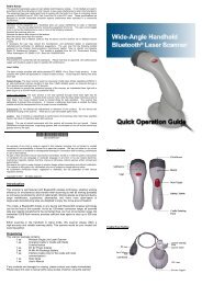
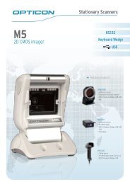
Figure 1 Scanner Features<br />
5<br />
6<br />
7<br />
10<br />
ITEM NO. DESCRIPTION<br />
1 Multi-functional Keypad<br />
2 Scan Button<br />
3 LCD display<br />
4 Red Output Window (Laser Aperture)<br />
5 Speaker for audible indicators<br />
6 Protective rubber bumpers<br />
7 Battery Compartment<br />
8 Communication Ports (RS232 and IrDA), Power Adapter Port, and Battery Contacts<br />
9 Comfort Strap<br />
10 Battery Compartment Release<br />
8<br />
9
General Features and Characteristics<br />
4<br />
3<br />
2<br />
1<br />
6<br />
5<br />
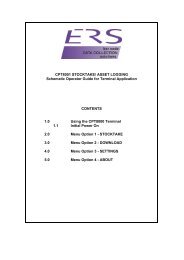
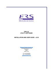
Figure 2. Cradle Features<br />
ITEM NO. DESCRIPTION<br />
1 LED Transmission Indicator<br />
2 LED Power indicator<br />
3 Battery Contacts<br />
4 IR communication port<br />
5 Rubber Footpads<br />
6 RS232 Communication Port and Power Adapter Port<br />
6
General Features and Characteristics<br />
Multifunctional Keypad<br />
5<br />
4<br />
3<br />
2<br />
1<br />
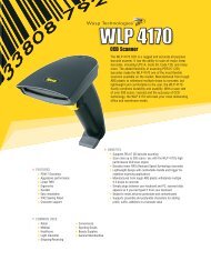
Figure 3.Keypad Features<br />
ITEM NO. KEY NAME DESCRIPTION<br />
1 ALPHA()<br />
2 ALPHANUMERIC<br />
The toggle key for Alphabet/Numeral input.<br />
When the system is in alpha-mode, a small icon will be shown in the lower right<br />
corner of the display. Each numeric key can be used to generate one of the three<br />
capital letters located on that number key. For example, numeral 2 can be used to<br />
produce A, B, or C. Pressing the same key twice within one second, will produce<br />
the letter B. Pressing the same key without halting longer than one second, will<br />
allow the user to toggle through the three letters. When the key has been<br />
depressed for longer than one second or another key has been pressed, the unit<br />
will send the real key code to the application program.<br />
Alphanumeric These 10 keys can be used for either alpha characters or<br />
numerical input. (See Item 8 for further description of key operation)<br />
3 ARROW<br />
Arrow.The two arrow keys located below the Scan key are used to toggle up and<br />
down between menu selections.<br />
4 ESC Escape. This key is used to stop and exit current operation<br />
5 SCAN Scan a bar code. Pressing this button will trigger the scanner to read a bar code<br />
6 ENTER<br />
7 BS<br />
8 FUNCTION(FN)<br />
9 POWER<br />
Enter. There are two enter keys on the side of the scan key. Normally the enter<br />
keys are used for command execution or input confirmation.<br />
Back Space This key can be used to toggle back one space or if pressed down<br />
longer than one second, a clear code will be sent<br />
The function key.<br />
This key cannot be activated alone; it must be pressed with one of the numeric<br />
keys at the same time. For example, FN + 1 generates function #1, FN + 2<br />
generates function #2, etc (up to 9 functions). Also, this key can be combined with<br />
the UP/DOWN arrow keys to adjust the contrast of the LCD. And when this key is<br />
combined with the ENTER key, it will turn ON/OFF the backlight.<br />
Power On/Off. To prevent an accidental power down, it requires about 1.5 sec of<br />
continuous pressing to turn On/Off the power.<br />
7<br />
6<br />
7<br />
8<br />
9
General Features and Characteristics<br />
The LCD Screen<br />
The LCD screen of the <strong>OptimusR</strong> Portable Data Terminal displays program settings, operational<br />
parameters, data collected, and much more. The display is a graphical LCD with the following<br />
characteristics:<br />
Display area of 64 pixels x 100 pixels<br />
Resolution:<br />
Maximum of 8 lines x 16 characters<br />
Minimum of 4 lines x 12 characters<br />
Displays alpha-characters, numbers, and symbols<br />
Automated back light<br />
The Lithium-Ion Battery<br />
The <strong>OptimusR</strong> Portable Data Terminal includes a<br />
lithium-ion rechargeable battery pack. The battery is<br />
inserted (See Getting Started for battery installation)<br />
into the battery compartment of the Optimus and<br />
recharges with Optimus in the cradle and in charging<br />
mode.<br />
8<br />
Figure 4 Lithium-Ion Battery
Installation<br />
Getting Started<br />
The <strong>OptimusR</strong> Portable Data Terminal (PDT) requires minimal effort to begin functional operation for<br />
data collection in any application. In order to get started the unit must have a fresh battery inserted into<br />
the battery compartment.<br />
1. Access the battery compartment by removing the battery cover. To remove the cover, pull the<br />
cover release up on each side of the compartment and slide the cover away form the unit.<br />
2. Insert the Li-ion battery into the battery compartment, battery information side up and battery<br />
contacts to the bottom, at an angle with the battery contacts inserted first.<br />
3. Push the Li-ion battery the remainder of the way into the compartment. The battery will fit<br />
snuggly into place.<br />
4. Close the battery compartment by sliding the battery cover toward the scan head until the<br />
cover locks into place.<br />
5. Turn the unit over, so the keypad is visible and hold down the power button .<br />
6. The LCD graphical display will display a menu and an audible indicator will sound to signify<br />
that the Optimus has been powered up properly.<br />
7. Using the arrow keys select the Run Program option.<br />
8. Scan a bar code.<br />
Note: The <strong>OptimusR</strong> comes with a default program loaded that allows users to scan items and enter<br />
their quantity. For information on how to create these programs, please refer to the Optimizer<br />
manual.<br />
9
Installation<br />
Basic Operation<br />
In order for the Optimus to operate properly, an application program must be loaded onto the PDT. It is<br />
possible for the Optimus to power up without at active application. On power up if the Optimus has no<br />
application program loaded, then the following Program Manager menu options will appear on the<br />
display:<br />
MENU OPTIONS. DESCRIPTION<br />
This option allows the user to download application programs (*.SHX), BASIC run-time<br />
(bas.ops.shx), BASIC programs (*.SYN) or font files to the terminal. There are 6 resident<br />
locations and one Active Memory. A maximum of 7 programs can be downloaded to the<br />
terminal. The application program downloaded to the Active Memory will be the only activate<br />
program running. In order to activate one of the other programs. Immediately after<br />
downloading, input a name for the program desired or just press the enter key to keep its<br />
current name if one is applicable. This will enable the user to download the program. The<br />
Download<br />
application file’s type, name, and size will be shown on the list of programs when entering the<br />
Download or Activate menu of the Program Manager. The file type is a small letter that<br />
follows the program number (01~06), it can be either ‘b’, ‘c’ or ‘f’ which represents BASIC<br />
program, C program or font file respectively. The program name is up to 12 characters and<br />
the program size is in units of K bytes.<br />
NOTE: In order to delete a program, select the program designated for deletion. From the<br />
program information screen, press the Alpha/Function key, then zero.<br />
This option will enable the use to activate one of the resident programs. In order to<br />
accomplish this, the user must copy one of the 6 resident programs to the Active Memory.<br />
Activate<br />
Upon activation of the new program the original program in the Active Memory will be<br />
replaced. Note: A font file cannot be activated, and a BASIC program cannot be activated if<br />
the BASIC run-time does not exist.<br />
The Upload option gives the user additional method for retrieving an application program. It<br />
Upload<br />
allows a user to transmit the application programs to a host PC or another terminal. This<br />
function also allows a terminal to be cloned without going through a PC.<br />
Selecting and successfully completing one of these three menu options will enable the <strong>OptimusR</strong> to<br />
begin functional operation.<br />
Communication and Data Collection Setup<br />
The <strong>OptimusR</strong> Series has various ways of communicating with a host device. Depending on the model<br />
of Optimus, it can communicate via RS232, USB, or via a WiFi connection. The <strong>OptimusR</strong> can store<br />
data in the unit or send data real time via a WiFi connection. The <strong>OptimusR</strong> has the ability to utilize a<br />
RS232 or USB connection to communicate to a host device for both application program downloads<br />
and data uploads. The <strong>OptimusR</strong> includes either a USB or RS232 cable. In order to begin an<br />
application download or data transfer the following steps would need to be followed.<br />
1. Remove the Optimus cradle, the power supply, and either the USB or RS232 cable from the box.<br />
2. Plug the power supply into a power outlet and insert the other end into the cradle. The red LED<br />
on the cradle will illuminate if the power supply is connected correctly.<br />
10
Installation<br />
3. Follow steps a, b, or c<br />
a. For the RS232 cable plug the 9 pin serial connector into a serial port on the host device.<br />
Plug the opposite end into the communication port of the cradle.<br />
b. For the USB cable plug the USB end of the cable into an appropriate communication port<br />
on the host device and the opposite end of the cable into the communication port of the<br />
cradle*.<br />
c. For the WiFi connection to communicate with the host device the settings on <strong>OptimusR</strong><br />
and the host device must be configured correctly.<br />
4. Power up the Optimus and select the Utilities option.<br />
5. This will open additional menu options. Select the Transfer Files option.<br />
6. Select Get Program on the next menu. The unit is now ready to download an application<br />
program.<br />
7. Place unit in cradle and download the appropriate application program.<br />
8. Once the Optimus has received the application program the unit is ready for scanning and<br />
collecting data.<br />
Note: There are <strong>OptimusR</strong> models available that do not include the cradle. Models<br />
that do not include a cradle as an accessory can have the power supply and the<br />
communication cable connected directly to the unit.<br />
*A software driver is required for proper installation. The driver is included with the installation CD provided with each<br />
Optimus. In addition the driver can be downloaded from http://www.metrologic.com.<br />
11
Installation<br />
Data Upload<br />
1. To transfer the data collected select the Utilities option.<br />
2. Select the Download Method option on the next menu and then select the appropriate method<br />
for downloading files to the host device.<br />
3. The WiFi can send data in real time, however, if cradle options (Cradle-IR or IrDA) are selected<br />
re-insert the Optimus unit into the cradle and upload the data to the host device.<br />
To change the download method select the Utilities option from the main menu and then select the<br />
download method from the list of available options. This allows the user to alter the method by which<br />
data is transferred to the host device.<br />
Note: Plugging the Optimus into a serial port or USB port on the host device does<br />
not guarantee communication with the Optimus. Ensure that the communication<br />
port on the host device is not populated by another device. Confirm that the<br />
communication settings on both the host device and the Optimus correspond prior<br />
to a program download or data upload.<br />
The <strong>OptimusR</strong>W is similarly connected to the host device and programmed however, there is a key<br />
difference in the data collection process. The <strong>OptimusR</strong>W supports transmission of data wirelessly and<br />
as such has the capability of communicating that data in real time. The unit needs to be setup to<br />
communicate with the network as follows:<br />
1. With the Optimus powered off press and hold the 7, 9, and power keys. The System Module<br />
menu will appear on screen.<br />
2. Using the arrow keys select the 802.11b Menu option.<br />
3. The list of settings that appears are the settings that require configuration in order for the WiFi to<br />
function effectively.<br />
4. Select Information option to view the current configuration settings on the Optimus.<br />
5. Select the Network Set option to configure the network settings. This is similar to enabling the<br />
network settings on a PC.<br />
6. Select WLAN Setting to select and configure the Optimus for the appropriate network available<br />
to connect to the host device.<br />
7. Select Security to setup any security/authentication settings that match the host device.<br />
8. Select the Echo test to test the settings and verify that the network settings on the Optimus are<br />
configured correctly and that the Optimus is communicating with the host device.<br />
9. Power off the Optimus.<br />
Upon completion of the configuration process, and depending on the active application program, the<br />
user will be able to begin data transmission via WiFi communication.<br />
Note: Contact a Metrologic Instruments representative if assistance is required<br />
when integrating a Metrologic device into a network.<br />
12
Installation<br />
The System Menu<br />
The system menu on the Optimus is another useful tool included with the Optimus. It provides<br />
information about the Optimus and access to the system menu for configuring the Optimus. In order to<br />
access the system module, follow the instructions below:<br />
1. With the Optimus powered off press down and hold the 7, 9, and power button.<br />
2. An audible indicator will sound to indicate that the Optimus is powered on.<br />
3. The Optimus will display the system menu.<br />
The system menu will list a number of options:<br />
• Information<br />
• Settings<br />
• Tests<br />
• Memory<br />
• Power<br />
• Load Program<br />
• 802.11 Menu<br />
System Menu Options<br />
Depending on the application program that is active on the Optimus, there are number of settings and<br />
options that may be selected for both setup and testing. The tables show a number of those settings<br />
and their descriptions.<br />
Information<br />
The Information option provides information about the Optimus including:<br />
• Hardware Version<br />
• Serial Number<br />
• Manufacturing Date<br />
• Application Program Version<br />
13
Installation<br />
Settings<br />
Tests<br />
SETTING DESCRIPTION DEFAULT<br />
Clock Set date and time for the system. N/A<br />
Backlight ON Period Set the duration for the keyboard/LCD backlight<br />
CPU Speed<br />
Auto Off<br />
Power On Options<br />
Key Click<br />
System Password<br />
Set CPU running speed. There are five speeds available:<br />
Full speed, half speed, quarter speed, eighth speed and<br />
sixteenth speed.<br />
Set time threshold for automatically power off when no<br />
operation is taking place during that specified period. If this<br />
value is set to zero, this function will be disabled.<br />
There are two possible selections: Program Resume, which<br />
starts from the program being used during the last session<br />
before the last power-off; and Program Restart, which starts<br />
with a new program.<br />
Select a tone for the beeper or disable the beeper when the<br />
user presses a key button.<br />
Set a password to protect the user from entering the system<br />
menu.<br />
14<br />
the light goes off after 20<br />
seconds<br />
Full speed<br />
10 minutes<br />
Program Resume<br />
Enable<br />
no password is set<br />
Font Current font displayed on the Optimus display System Font<br />
Reset to Default Resets the system settings to the default settings N/A<br />
The <strong>OptimusR</strong> has numerous tests available to the user for both operation and diagnostics. Depending<br />
on the application program that is in the active memory will determine which tests can be performed and<br />
are available to the user. The following table provides a description of the available tests.<br />
SETTING DESCRIPTION DEFAULTS<br />
Reader<br />
Buzzer<br />
LCD & LED<br />
Keyboard<br />
Memory<br />
Echo Test<br />
To test the reading performance of the scanner. The following symbologies are enabled for<br />
the Reader test. All other symbologies will need to be enabled via programming.<br />
Default Bar codes: Code 39, Industrial 25, Interleave 25,Codabar, Code 93, Code 128,<br />
UPCE, UPCE with ADDON 2, UPCE with ADDON 5, EAN8, EAN8 with ADDON 2<br />
EAN8 with ADDON 5, EAN13, EAN13 with ADDON 2, EAN13 with ADDON 5<br />
To test the buzzer with different Frequency/Duration. Press ENTER key to start and then<br />
press any key to stop the test.<br />
To test LCD display and LED indicator. Press ENTER key to start and then press any key to<br />
stop the test.<br />
To test the rubber keys. Press a key and the result will be shown on the LCD display. Note<br />
that the FN key should be used in conjunction with numeral keys.<br />
To test the data memory (SRAM). Note after the test, the contents of the memory space will<br />
be wiped out.<br />
Warning: This test erases any data stored in the terminal.<br />
Echo Test is used to test the communication between the cradle and the PC. Perform Echo<br />
test from the host device that the cradle is connected.
Installation<br />
Memory<br />
The menu option provides the user with ability to gather information on the amount of memory available<br />
on the Optimus, as well as the ability to initialize the memory. This is accomplished by choosing one of<br />
the two available selections.<br />
1. Size Info.<br />
2. Initialize<br />
Size Info.<br />
The Optimus contains two types of memory, SRAM and Flash memory. These two types of memory<br />
allow the Optimus to perform operational tasks at an optimal level.<br />
Power<br />
Base RAM: The Base RAM is the primary memory in the Optimus and is the location where<br />
application is stored and accessed.<br />
Memory Card: The Memory Card is basically SRAM and is memory that retains data as long<br />
as power is being supplied. SRAM does not have to be periodically refreshed and provides<br />
quick access to data. This is the location that the data collected will be stored.<br />
Flash memory: Flash memory is a type of constantly-powered nonvolatile memory that can be<br />
erased and reprogrammed easily. This allows users to program the Optimus effortlessly.<br />
Initialize<br />
This selection enables the user of the Optimus to initialize the memory (SRAM).<br />
Warning: Initializing the memory will erase the current data in memory.<br />
Selecting the power option allows the user to view the actual voltages of the main battery and the<br />
backup battery.<br />
Load Program<br />
The selection of Load Program enables the user to download an application program to the Optimus.<br />
Note: For further information on application program downloads see the Optimizer User’s guide.<br />
15
Installation<br />
802.11b Menu<br />
The 802.11b Menu settings will configure the <strong>OptimusR</strong> with the appropriate network and security<br />
settings for WiFi communication.<br />
1. Information<br />
2. Network Set<br />
3. WLAN Setting<br />
4. Security<br />
5. Echo Test<br />
Information<br />
The information setting list the current network settings of the <strong>OptimusR</strong>.<br />
Network Set<br />
These are the network settings for the <strong>OptimusR</strong>.<br />
1. DHCP<br />
2. SubNet Mask<br />
3. Local IP<br />
4. Gateway<br />
5. DNS Server<br />
6. Domain Name<br />
WLAN Setting<br />
These are the Wireless Local Area Network settings.<br />
1. Local Name<br />
2. SS ID<br />
3. System Scale<br />
4. Power Saving<br />
5. Preamble<br />
6. Ad-Hoc<br />
Security<br />
The security settings provide network authentication configuration settings to provide secure data<br />
transfer.<br />
1. Authentications<br />
2. WEP (Wired Equivalent Privacy) Menu<br />
3. EAP (Extensible Authentication Protocol) Menu<br />
Echo Test<br />
Modifying TCP/IP settings can affect the<br />
performance of certain devices. Contact an IT<br />
professional to ensure that modifying these<br />
settings is done correctly.<br />
Test to verify that the network settings are correct and communication from Optimus to host device<br />
is functioning.<br />
16
Installation<br />
Application<br />
The Application module runs on top of the System module. The <strong>OptimusR</strong> Series Portable Data<br />
Terminals are preloaded with the Optimizer’s run-time program and the following menu will be shown<br />
upon powering the unit up:<br />
Models ():<br />
1. Run Program<br />
2. Utilities<br />
Utilizing the arrow keys select the menu option and execute it by pressing the ENTER key. For certain<br />
models of the <strong>OptimusR</strong> Series the Data Optimizer program may need to be used in order to handle the<br />
in-coming and out-going data to and from a host device. For detailed information, please refer to<br />
“Optimizer User’s Guide” and “DataOptimizer User’s Guide”.<br />
Note: If the Application Generator is used to create the application program, it will be necessary to<br />
download it to the terminal.<br />
Programming the terminal<br />
There are three software tools available for developing application programs for the terminal.<br />
• The Optimizer Program Builder<br />
• The “BASIC” Compiler<br />
• The “C” Compiler<br />
For detailed information, please consult the appropriate manual or contact Metrologic Instruments, Inc..<br />
Programming the communication cradle<br />
The communication cradle of the <strong>OptimusR</strong> Portable Data Terminal supports serial IR interface only. If a<br />
customized PC application has been developed for communication with the terminal via the cradle, it<br />
will be necessary to first configure the cradle through programming. There is a DLL available for this<br />
purpose.<br />
For more information, please contact Metrologic Instruments, Inc..<br />
17
Troubleshooting<br />
SYMPTOM DESCRIPTION<br />
Does not power up after<br />
pressing POWER key.<br />
Make sure the battery is inserted and charged.<br />
Charge the battery and check the charging status. If no charging information shown on<br />
the display, reload the battery and check if the battery is properly installed then try again.<br />
Call for service if problem persists.<br />
Check if the cable is plugged tightly into host device and cradle.<br />
Cannot transmit data or Perform Echo test to confirm communication.<br />
programs to/from the terminal Check if host communication parameters (COM port, baud rate, data bits, parity, and<br />
stop bit) match with the Terminal's.<br />
Verify that the communication port on the host device is not in use by another device.<br />
Keypad does not work<br />
properly<br />
Scanner does not scan<br />
Abnormal responses<br />
Turn off the power then enter the system menu. From the system menu, select the Test<br />
and then its sub-item KBD. Perform the key-in test.<br />
Call for service if problem persists.<br />
Check if the bar codes used are enabled<br />
Check if battery-low indicator is shown on the LCD display. If yes, charge the battery<br />
Call for service if problem persists.<br />
Open the battery cap and re-load the battery.<br />
Enter system menu. Run diagnostic test.<br />
Call for service if problem persists.<br />
18
Specifications<br />
OPERATIONAL<br />
Single-Line<br />
Light Source: Visible Laser Diode (VLD) @ 650 nm<br />
Normal Depth of Field:<br />
51 mm - 381 mm<br />
(2"- 15")<br />
0.33 mm (13 mil)<br />
bar code<br />
Width of Scan Field: 305mm (12”) @ 381 mm (15”)<br />
Scan Speed: 42 scan lines per second<br />
No. of Scan Lines: 1<br />
Min Bar Width: 0.127 mm (5.0 mil)<br />
Decode Capability:<br />
19<br />
OPTIMUSR SERIES<br />
All standard 1-D bar codes including RSS-14,<br />
RSS-Expanded, and RSS-14 Limited<br />
Print Contrast: 35% minimum reflectance difference<br />
No. Characters Read:<br />
Up to 80 data characters<br />
Maximum number will vary based on symbology and density.<br />
Beeper Operation: 7 tones or no beep<br />
CPU: 16-bit CMOS, low power consumption<br />
Program Memory: 2 MB Flash ROM<br />
Data Memory: 2 MB SRAM, expandable to 8 MB<br />
Display: LCD 128 x 64 pixels, back-lit<br />
Display Resolution: 8 lines x 20 Characters (max), 4 Lines x 15 characters (min)<br />
Communication (Unit): RS232, USB, IrDA, CradleIR or WiFi<br />
Communication (Cradle): RS232 or USB<br />
Application Development: Windows-based Optmizer; optional C & BASIC compilers
Specifications<br />
MECHANICAL<br />
ELECTRICAL<br />
ENVIRONMENTAL<br />
Width (Unit): 81 mm (3.2")<br />
Depth (Unit): 46 mm (1.8")<br />
Height (Unit): 172 mm (6.77")<br />
Weight (Unit): 10.6 oz (300 g) – including battery<br />
Width (Cradle): 96 mm (3.8")<br />
Depth (Cradle): 106 mm (4.17")<br />
Height (Cradle): 80 mm (3.15")<br />
Battery Operation: Li-ion<br />
20<br />
OPTIMUSR SERIES<br />
Battery Backup: 3.7V, 7.0mA hours, rechargeable lithium battery<br />
Operation: Over 200 hours, Over 16 hours (WiFi)<br />
Laser Class:<br />
CDHR and IEC Class 2 in accordance with<br />
IEC 60825 – 1:1993 + A1:1997 + A2:2001<br />
EMC: FCC Class B<br />
Operating Temperature: 0°C to 50°C (32°F to 122°F)<br />
Storage Temperature: -20°C to 60°C (-4°F to 140°F)<br />
Humidity: 5% to 95% relative humidity, non-condensing<br />
Shock Resistance: 1.2 m (4’) drop onto concrete<br />
Figure 5 Scan Areas
Contact Information and Office Locations<br />
Corporate Headquarters European, Middle East and Asian Headquarters - Singapore<br />
Metrologic Instruments, Inc. African HQ & Germany Office Singapore<br />
90 Coles Road Eastern Europe and Middle East Metrologic Asia (Pte) Ltd<br />
Blackwood, NJ 08012-4683 Metrologic Instruments GmbH 50 Kallang Avenue<br />
Tel: 856-228-8100 Dornierstrasse 2 #01-02<br />
Fax: 856-228-6673 (Sales) 82178 Puchheim Noel Corporate Building<br />
Fax: 856-228-1879 (Marketing) Munich, Germany Singapore 339505<br />
Fax: 856-228-0653 (Legal/Finance) Tel: 49-89-89019-222 Tel : (65) 6842-7155<br />
Email: info@metrologic.com Fax: 49-89-89019-173 Fax : (65) 6842-7166<br />
Email: info@east.metrologic.com Email: info@sg.metrologic.com<br />
North America France China<br />
Metrologic The Americas Metrologic Eria France SA MTLG AutoID Instr. (Shanghai) Co.,Ltd<br />
1571 Imperial Way 69 Rue de la Belle Etoile Room 1419, No.1 Ji long Road<br />
Suite B ZI Paris Nord II, BP 50057 Waigaoqiao Bonded Zone<br />
West Deptford, NJ 08066 95947 – ROISSY CDG CEDEX Shanghai 200000<br />
Tel: 1.856.537.6400 Tel: +33 (0) 1 48.63.78.78 Tel: 86-21-58692780<br />
Fax: 1.856.537.6474 Fax: +33 (0) 1 48.63.24.94 Fax:86-21-58692782<br />
Email: info@us.metrologic.com Email: info@fr.metrologic.com Email: info@cn.metrologic.com<br />
Adaptive Optics Associates (AOA) Italy China<br />
Ten Wilson Road Metrologic Instruments Italia srl Suzhou Sales Office<br />
Cambridge, MA 02138-1128 Via Emilia 70 BLK A, Room# 03/03-04<br />
Tel: 617-806-1400 40064 Ozzano dell’Emilia (BO) No.5 Xinghan Str., Xinsu Industrial Sq<br />
Fax: 617-806-1899 Tel: +39 0 51 6511978 China-Singapore Suzhou Industrial<br />
Email: info@aoainc.com Fax: +39 0 51 6521337 Park,Suzhou, PRC<br />
Email: info@it.metrologic.com Tel: 86-512-67622550<br />
Omniplanar Fax: 86-512-67622560<br />
1571 Imperial Way Poland Email: info@cn.metrologic.com<br />
Suite A Metrologic Instruments Poland Sp.z o.o<br />
West Deptford, NJ Poleczki 21 China<br />
Tel: 856.537.6100 02-822 Warsaw, Poland Guangzhou Sales Office<br />
Fax: 856.537.6116 Tel: +48 (22) 545 04 30 Room 2307<br />
Email: info@omniplanar.com Fax:+48 (22) 545 04 31 Foreign Economic and Trade Bldg<br />
Email:info@pl.metrologic.com #351 Tianhe Road<br />
Guangzhou City, Guangdong<br />
Province, PRC<br />
Tel: 86-20-38823476<br />
Fax: 86-20-38823477<br />
Email: info@cn.metrologic.com<br />
21
Contact Information and Office Locations<br />
South America and Central America European, Middle East and<br />
African Headquarters<br />
Asian Headquarters - Singapore<br />
Brazil Russia China<br />
Metrologic do Brasil Ltda. Metrologic Russia Beijing Sales Office<br />
Rua da Paz 2059 Bolshaya Novodmitrovskaya 14 Tower A, 5th Floor, Unit 5204<br />
CEP 04713-002 RU-125015 China Intn'l Science and Tech<br />
Chácara Santo Antônio Moscow Russia Convention Ctr<br />
São Paulo, <strong>SP</strong>, Brasil Tel: +7 095 730 7424 No. 12 Yu Min Road Chao Yang Dist<br />
Tel: 55-11-5182-8226 Fax: +7 095 730 7425 Beijing China 100029<br />
Fax: 55-11-5182-8315 Email: info@ru.metrologic.com Tel/Fax: 86 10 82253472<br />
Email: info@br.metrologic.com<br />
Spain<br />
Email: info@cn.metrologic.com<br />
Outside Brazil Metrologic Eria Ibérica, SL India<br />
Metrologic South America Julián Camarillo 29, D-1 Metrologic India<br />
Rua da Paz 2059 28037 Madrid 403, 4th Floor Carlton Towers<br />
CEP 04713-002 Tel: +34 913 272 400 No. 1, Airport Road<br />
Chácara Santo Antônio Fax: +34 913 273 829 Bangalore, India 560 008<br />
São Paulo, <strong>SP</strong>, Brasil Email: info@es.metrologic.com Tel: +91 80 51256718<br />
Tel: 55-11-5182-7273 Fax: +91 80 51256719<br />
Fax: 55-11-5182-7198 Metrologic European Repair Ctr Email: info@in.metrologic.com<br />
Email: info@sa.metrologic.com (MERC)<br />
Metrologic Eria Ibérica, SL Japan<br />
European, Middle East and C/ Alfonso Gomez, 38-40, 1D Metrologic Japan Co., Ltd.<br />
African Headquarters 28037 Madrid Matsunoya Building, 6 Floor<br />
Metrologic Instruments GmbH Tel: +34 913 751 249 3-14-8 Higashiueno<br />
Dornierstrasse 2 Fax: +34 913 270 437 Taitou-ku, Tokyo 110-0015 Japan<br />
82178 Puchheim Tel: 81-3-3839-8511<br />
Munich, Germany United Kingdom Fax: 81-3-3839-8519<br />
Tel: 49-89-89019-0 Metrologic Instruments UK Ltd Email: info@jp.metrologic.com<br />
Fax: 49-89-89019-200 58 Tempus Business Centre<br />
Email: info@europe.metrologic.com Kingsclere Road, Basingstoke<br />
Hampshire RG21 6XG<br />
Germany, Austria and Switzerland Tel: +44 (0) 1256 365900<br />
Metrologic Instruments GmbH Fax: +44 (0) 1256 365955<br />
Dornierstrasse 2 Email: info@uk.metrologic.com<br />
82178 Puchheim Kingsclere Road, Basingstoke<br />
Munich, Germany Hampshire RG21 6XG<br />
Tel: 49-89-89019-0 Tel: +44 (0) 1256 365900<br />
fax: 49-89-89019-200 Fax: +44 (0) 1256 365955<br />
Email: info@de.metrologic.com Email: info@uk.metrologic.com<br />
22
Safety Notices<br />
This equipment has been tested and found to comply with the limits for a Class B digital device,<br />
pursuant to Part 15 of the FCC Rules. These limits are designed to provide reasonable protection<br />
against harmful interference in a residential installation. This equipment generates, uses, and can<br />
radiate radio frequency energy and, if not installed and used in accordance with the instructions, may<br />
cause harmful interference to radio communications. However, there is no guarantee that interference<br />
will not occur in a particular installation. If this equipment does cause harmful interference to radio or<br />
television reception, which can be determined by turning the equipment off and on, the user is<br />
encouraged to try to correct the interference by one of the following measures:<br />
• Reposition or relocate the receiving antenna.<br />
• Increase the separation between the equipment and receiver.<br />
• Connect the equipment into an outlet on a circuit different from that to which the receiver is<br />
connected.<br />
• Consult the dealer or an experienced radio/TV technician for help.<br />
This device complies with Part 15 of the FCC Rules. Operation is subject to the following two<br />
conditions: (1) This device may not cause harmful interference, and (2) this device must accept any<br />
interference received, including interference that may cause undesired operation.<br />
Any changes or modifications not expressly approved by the party responsible for compliance could<br />
void the user's authority to operate this equipment.<br />
23