Lösningar till Tentamen i Signaler och kommunikation, ETT080 ... - EIT
Lösningar till Tentamen i Signaler och kommunikation, ETT080 ... - EIT
Lösningar till Tentamen i Signaler och kommunikation, ETT080 ... - EIT

You also want an ePaper? Increase the reach of your titles
YUMPU automatically turns print PDFs into web optimized ePapers that Google loves.
<strong>Lösningar</strong> <strong>till</strong> <strong>Tentamen</strong> i <strong>Signaler</strong> <strong>och</strong> <strong>kommunikation</strong>, <strong>ETT080</strong>, 2 juni 2006, kl 14–19 1<br />
Uppgift 1<br />
(a) In the z-transform domain the transfer function becomes<br />
H(z) = 1 − 0.8z−1 + 0.6z −2<br />
1 − 0.2z −1 − 0.9z −2 = z2 − 0.8z + 0.6<br />
z 2 − 0.2z − 0.9z 2 = z2 − 0.8z + 0.6<br />
(z − 1.05)(z + 0.85)<br />
Hence, the system is non-stable.<br />
Answer:False<br />
(b) Counter example: The system with impulse response h[n] = δ[n] is clearly stable. The unit step<br />
response is ys[n] = µ[n]. The energy is<br />
∞<br />
n=−∞<br />
y 2 s[n] =<br />
∞<br />
1 = ∞<br />
n=0<br />
Answer:False<br />
(c) As the unit circle is followed from 0 rad to π rad, there are two zeros both in the beginning and<br />
in the end. In between the zeros there are a couple of poles affecting the frequency response. We<br />
conclude that the amplitude response should be more attenuated in the beginning and the end of<br />
the frequency interval, and less attenuated in between. Therefore, it should be a band pass filter.<br />
Answer:True<br />
(d) Firstly, assume that d0 = 0. The series expansion of H(z) is then<br />
H(z) = p0<br />
+ h1z<br />
d0<br />
−1 + h2z −2 + · · ·<br />
Z−1 → p0<br />
d0<br />
δ[n] + h1δ[n − 1] + h2δ[n − 2] + · · ·<br />
and we see that the system is causal. Secondly, assume that d0 = 0. Then the transfer function<br />
becomes<br />
H(z) = po + p1z−1 + · · · + pMz −M<br />
d1z−1 + · · · + dNz −N = z po + p1z−1 + · · · + pMz −M<br />
d1 + · · · + dNz −N+1<br />
<br />
= z ˜h0 + ˜ h1z −1 + ˜ h2z −2 <br />
+ · · ·<br />
Z −1<br />
→ ˜ h0δ[n + 1] + ˜ h1δ[n] + ˜ h2δ[n − 1] + · · ·<br />
which is non-causal.<br />
Answer:True<br />
(e) Consider the 8 point DFT of x = (10000000). This becomes x = (11111111). Clearly, the<br />
relation is not true for this example.<br />
Answer:False<br />
Uppgift 2<br />
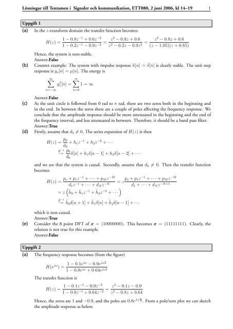
(a) The frequency response becomes (from the figure)<br />
H(e jω ) = 1 − 0.1ejω − 0.9e jω2<br />
1 − 0.8e jω + 0.64e jω2<br />
The transfer function is<br />
H(z) = 1 − 0.1z−1 − 0.9z −2<br />
1 − 0.8z −1 + 0.64z −2 = z2 − 0.1z − 0.9<br />
z 2 − 0.8z + 0.64<br />
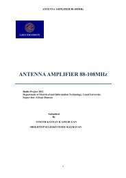
Hence, the zeros are 1 and −0.9, and the poles are 0.8e ±j π<br />
3 . From a pole/zero plot we can sketch<br />
the amplitude response as below.
<strong>Lösningar</strong> <strong>till</strong> <strong>Tentamen</strong> i <strong>Signaler</strong> <strong>och</strong> <strong>kommunikation</strong>, <strong>ETT080</strong>, 2 juni 2006, kl 14–19 2<br />
Imaginary Part<br />
1<br />
0.5<br />
0<br />
−0.5<br />
−1<br />
−1 −0.5 0<br />
Real Part<br />
0.5 1<br />
6<br />
5<br />
4<br />
3<br />
2<br />
1<br />
0<br />
0 pi<br />
we can easily derive that the ending point is |H(e jπ )| = 0.08 and that |H(e jπ/3 )| = 5.3.<br />
(b) The Z-transform of the step response is<br />
Y (z) =<br />
=<br />
=<br />
1<br />
H(z) =<br />
1 − z−1 1 + 0.9z −1<br />
π<br />
j (1 − 0.8e 3 z−1 π<br />
−j )(1 − 0.8e 3 z−1 )<br />
1 + 0.9z−1 1 − 2 · 0.8 cos( π<br />
3 )z−1 + 0.82z−2 1 − 0.8 cos( π<br />
3 )z−1<br />
1 − 2 · 0.8 cos( π<br />
3 )z−1 + 0.82 2.6<br />
+<br />
z−2 from the Z-transform table we get<br />
0.8 √ 3<br />
y[n] = 0.8 n cos( π 2.6<br />
n)µ[n] +<br />
3 0.8 √ 3 0.8n sin( π<br />
3 n)µ[n]<br />
= 0.8 n<br />
<br />
cos( π<br />
n) + 1.9 sin(π<br />
3 3 n)<br />
<br />
µ[n]<br />
0.8 sin( π<br />
3 )z−1<br />
1 − 2 · 0.8 cos( π<br />
3 )z−1 + 0.82z−2 (c) We know that if the input is x[n] = A cos( π<br />
π<br />
n + φ), the output is x[n] = A|H(ej 2 )| cos( 2 πn<br />
+ 2<br />
) + φ). To get the desired result we put<br />
Θ( π<br />
2<br />
Uppgift 3<br />
A =<br />
1<br />
π<br />
j |H(e 2 )|<br />
≈ 0.46<br />
φ = −Θ( π<br />
) ≈ 1.095<br />
2<br />
Sampling with sampling rate Fs gives a periodic repetition of the spectra with period Fs. Therefore, a<br />
signal frequency f0 will occur at the frequencies<br />
f = ±f0 + kFs, k ∈ Z<br />
The reconstructed signal is the part of the spectra that lies in the interval −Fs/2 < f < Fs/2.<br />
(a) If Fs = 320Hz the reconstructed signal is in −160Hz < f < 160Hz. The recorded sounds in the<br />
problem becomes reconstructed at<br />
Insekt f [Hz]<br />
Ollonborre 50<br />
Blomfluga 120<br />
Humla 130<br />
Husfluga 120<br />
Mygga 40<br />
Knott 86
<strong>Lösningar</strong> <strong>till</strong> <strong>Tentamen</strong> i <strong>Signaler</strong> <strong>och</strong> <strong>kommunikation</strong>, <strong>ETT080</strong>, 2 juni 2006, kl 14–19 3<br />
(b) Use a sapling frequency such that the bumble bees are reconstructed at 20Hz. Then everything<br />
below cannot be heard, and the frequencies above can be attenuated by the analog filter after<br />
reconstruction. Use, e.g., Fs = 150Hz to do this. In the following table we check that it is only<br />
the bumble bees that are aliased to 20Hz.<br />
Insekt f [Hz]<br />
Ollonborre 50<br />
Blomfluga 30<br />
Humla 20<br />
Husfluga 50<br />
Mygga 0<br />
Knott 4<br />
Use Fc = 25Hz as a cut off frequency for the filter.<br />
Uppgift 4<br />
Construct the filter as a cascade of two filters, one LP filter and one notch filter. Together they should<br />
have at most order 5, which means that we can construct an order 2 notch filter and an order 3 LP filter.<br />
Start with the LP filter. The frequencies between 3400Hz and 4000Hz should be attenuated. In the<br />
sampled frequency this corresponds to ω3400 = 3400 17 π = 4000 20π and ω4000 = π. One (easy) way to<br />
17π<br />
17π<br />
±j ±j construct such filter is to consider zeros at e 20 and -1, and the corresponding poles at Ae 20 and -B,<br />
where both A and B are positive constants less than 1. The transfer function becomes<br />
HLP (z) =<br />
=<br />
(1 + z−1 17π<br />
j )(1 + e 20 z−1 17π<br />
−j )(1 + e 20 z−1 )<br />
(1 + Bz−1 17π<br />
j )(1 + Ae 20 z−1 17π<br />
−j )(1 + Ae 20 z−1 )<br />
1 + (1 − 2 cos 17<br />
20 )z−1 + (1 − 2 cos 17<br />
20 )z−2 + z−3 1 + (B − 2A cos 17<br />
20 )z−1 + (A2 − 2AB cos 17<br />
20 )z−2 + A2Bz −3<br />
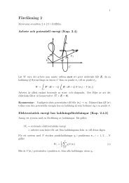
With A = 0.8 and B = 0.7 the zero/pole plot and the amplitude response becomes<br />
Imaginary Part<br />
1<br />
0.5<br />
0<br />
−0.5<br />
−1<br />
−1 −0.5 0<br />
Real Part<br />
0.5 1<br />
1.5<br />
1<br />
0.5<br />
0<br />
0 pi<br />
The 50Hz disturber can be cancelled with a notch filter with notch frequency ω50 = 50<br />
transfer function is<br />
HN(z) =<br />
π<br />
(1 + ej 80 z−1 π<br />
−j )(1 + e 80 z−1 )<br />
π<br />
j (1 + Ce 80 z−1 π<br />
−j )(1 + Ce 80 z−1 )<br />
where C is a positive constant less than 1. With C = 0.9 we get<br />
= 1 − 2 cos 1<br />
80 z−1 + z −2<br />
1 − 2C cos 1<br />
80 z−1 + C 2 z −2<br />
4000<br />
1 π = π. The<br />
80
<strong>Lösningar</strong> <strong>till</strong> <strong>Tentamen</strong> i <strong>Signaler</strong> <strong>och</strong> <strong>kommunikation</strong>, <strong>ETT080</strong>, 2 juni 2006, kl 14–19 4<br />
Imaginary Part<br />
1<br />
0.5<br />
0<br />
−0.5<br />
−1<br />
−1 −0.5 0<br />
Real Part<br />
0.5 1<br />
1.4<br />
1.2<br />
1<br />
0.8<br />
0.6<br />
0.4<br />
0.2<br />
0<br />
0 pi<br />
Using those two filters in cascade we get the following zero/pole plot and amplitude function<br />
Imaginary Part<br />
1<br />
0.5<br />
0<br />
−0.5<br />
−1<br />
−1 −0.5 0<br />
Real Part<br />
0.5 1<br />
The figures of the filters realisations are omitted.<br />
Uppgift 5<br />
1.6<br />
1.4<br />
1.2<br />
1<br />
0.8<br />
0.6<br />
0.4<br />
0.2<br />
0<br />
0 pi<br />
(a) There are 48 channels. If each uses M signal alternatives the total number of signals becomes<br />
⎧<br />
M 48 ⎪⎨<br />
=<br />
⎪⎩<br />
2 48 ≈ 10 14 , 2-PAM<br />
4 48 ≈ 10 30 , 4-QAM<br />
16 48 ≈ 10 58 , 16-QAM<br />
64 48 ≈ 10 87 , 64-QAM<br />
(b) Let k ∈ {1, 2, 4, 6} be the number of bits per transmitted signal in one channel. Then, the actual<br />
transmitted bit rate for channel n is<br />
Rb,n = k<br />
·<br />
Ts<br />
3<br />
⎧<br />
0.1875Mbps,<br />
⎪⎨<br />
0.375Mbps,<br />
4<br />
⎪⎩<br />
0.75Mbps,<br />
1.125Mbps,<br />
2-PAM<br />
4-QAM<br />
16-QAM<br />
64-QAM<br />
The maximum and minimum bit rate becomes<br />
Rb,min = 0.1875 · 48 = 9Mbps<br />
Rb,max = 1.125 · 48 = 54Mbps<br />
(c) The signal in channel n is<br />
si,n(t) = ainA cos(2πfnt) − binA sin(2πfnt)
<strong>Lösningar</strong> <strong>till</strong> <strong>Tentamen</strong> i <strong>Signaler</strong> <strong>och</strong> <strong>kommunikation</strong>, <strong>ETT080</strong>, 2 juni 2006, kl 14–19 5<br />
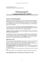
This is the formula for QAM with a rectangular base pulse. Hence, the spectral density for channel<br />
n is a sinc, see figure below. The sinc has zero for all values of fn + m/Ts, where m is a nonzero<br />
integer. These zeros are used to position other carriers, see the following figure with 4 carriers.<br />
Therefore, at the carrier frequencies, the signals in different channels do not interfear, which is the<br />
origin of orthogonal in OFDM.<br />
1<br />
0<br />
(d) For a rectangular pulse W99 = 20.6/Ts. That means that the contribution on each side of the<br />
main lobe is ∆ = 9.3/Ts. An estimate of the 99% bandwidth of a 48 channel OFDM can be<br />
given by the width of the main lobes plus a ∆ on each side,<br />
W99,OFDM 48<br />
+ 2∆ = 14.3MHz<br />
Ts<br />
The maximum bandwidth efficiency is<br />
ρmax = Rb,max<br />
W99,OFDM<br />
≈ 3.8bps/Hz<br />
The bit rate for a comparable 64-QAM system is<br />
Rb = k<br />
T<br />
· 3<br />
4<br />
= 6<br />
T<br />
· 3<br />
4<br />
= 54Mbps<br />
The symbol time then becomes T = 8.3 · 10 8 s. The 99% bandwidth is (with a rectangular pulse)<br />
W99 = 20.6/T = 247MHz, and the bandwidth efficiency becomes ρ = 0.22bps/Hz. We see in<br />
this comparison that OFDM is an efficient way to use the band width.<br />
1<br />
0