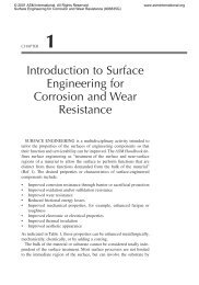
Fatigue Crack Propagation - ASM International
Fatigue Crack Propagation - ASM International
Fatigue Crack Propagation - ASM International

You also want an ePaper? Increase the reach of your titles
YUMPU automatically turns print PDFs into web optimized ePapers that Google loves.
TECH<br />
SPOTLIGHT FATIGUE CRACK<br />
PROPAGATION<br />
George<br />
Totten*<br />
G.E. Totten &<br />
Associates<br />
LLC<br />
Seattle,<br />
Washington<br />
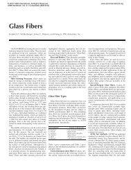
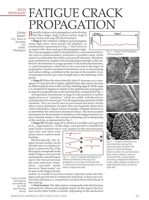
Basically, fatigue crack propagation can be divided<br />
Stage I Stage II<br />
into three stages: stage I (short cracks), stage II<br />
(long cracks) and stage III (final fracture).<br />
• Stage I: Once initiated, a fatigue crack propagates<br />
along high shear stress planes (45 degrees), as<br />
schematically represented in Fig. 1. This is known<br />
as stage I or the short crack growth propagation stage.<br />
The crack propagates until it is decelerated by a microstructural barrier<br />
such as a grain boundary, inclusions, or pearlitic zones, which<br />
cannot accommodate the initial crack growth direction. Therefore,<br />
grain refinement is capable of increasing fatigue strength of the material<br />
by the insertion of a large quantity of microstructural barriers,<br />
i.e. grain boundaries, which have to be overcome in the stage I of<br />
propagation. Surface mechanical treatments such as shot peening<br />
and surface rolling, contribute to the increase in the number of microstructural<br />
barriers per unit of length due to the flattening of the<br />
grains.<br />
• Stage II: When the stress intensity factor K increases as a consequence<br />
of crack growth or higher applied loads, slips start to develop<br />
in different planes close to the crack tip, initiating stage II. While stage<br />
I is orientated 45 degrees in relation to the applied load, propagation<br />
in stage II is perpendicular to the load direction, as depicted in Fig. 1.<br />
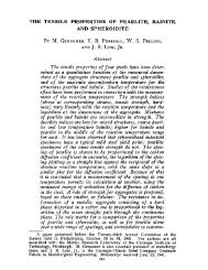
An important characteristic of stage II is the presence of surface<br />
ripples known as “striations,” which are visible with the aid of a<br />
scanning electron microscope. Not all engineering materials exhibit<br />
striations. They are clearly seen in pure metals and many ductile<br />
alloys such as aluminum. In steels, they are frequently observed in<br />
cold-worked alloys. Figure 2 shows examples of fatigue striations in<br />
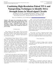
an interstitial-free steel and in aluminum alloys. The most accepted<br />
mechanism for the formation of striations on the fatigue fracture surface<br />
of ductile metals, is the successive blunting and re-sharpening<br />
of the crack tip, as represented in Fig. 3.<br />
• Stage III: Finally, stage III is related to unstable crack growth<br />
as Kmax approaches KIC. At this stage, crack growth is controlled by<br />
static modes of failure and is very sensitive to the microstructure,<br />
load ratio, and stress state<br />
(plane stress or plane strain<br />
loading).<br />
a<br />
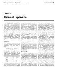
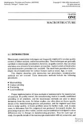
Macroscopically, the fatigue<br />
fracture surface can be<br />
divided into two distinct regions,<br />
as shown by Fig. 4.The<br />
first region corresponds to the<br />
b<br />
d<br />
e<br />
stable fatigue crack growth c<br />
and presents a smooth aspect Fig. 3 — Laird´s proposed mechanisms of<br />
due to the friction between striation formation in the stage II of<br />
the crack wake faces. Sometimes,<br />
concentric marks<br />
known as “beach marks” can<br />
be seen on the fatigue fracture<br />
propagation: (a) no load; (b) tensile load;<br />
(c) maximum tensile load; (d) load reversion<br />
and (e) compressive load.<br />
surface, as a result of successive arrests or decrease in the rate of fatigue<br />
crack growth due to a temporary load drop, or due to an overload<br />
that introduces a compressive residual stress field ahead of<br />
the crack tip.<br />
• Final fracture: The other region corresponds to the final fracture<br />
and presents a fibrous and irregular aspect. In this region, the fracture<br />
can be either brittle or ductile, depending on the mechanical<br />
* Fellow of <strong>ASM</strong><br />
<strong>International</strong><br />
and member of<br />
the <strong>ASM</strong><br />
Heat Treating<br />
Society<br />
Fig. 1— Stages I and II of fatigue<br />
crack propagation.<br />
Fig. 2 — <strong>Fatigue</strong> striations in (a)<br />
interstitial free steel and (b)<br />
aluminum alloy AA2024-T42.<br />
Figure (c) shows the fatigue<br />
fracture surface of a cast aluminum<br />
alloy, where a fatigue crack was<br />
nucleated from a casting defect,<br />
presenting solidification dendrites<br />
on the surface; fatigue striations are<br />
indicated by the arrow, on the top<br />
right side.<br />
ADVANCED MATERIALS & PROCESSES/MAY 2008 39<br />
Surface<br />
5 m<br />
2 m<br />
40 m
a<br />
Fast fracture<br />
b<br />
Fast fracture<br />
<strong>Fatigue</strong> crack<br />
<strong>Fatigue</strong> crack<br />
propagation Initiation15 mm propagation Initiation<br />
Fig. 4 — <strong>Fatigue</strong> fracture surface: (a) high applied load; (b) low applied load.<br />
20mm<br />
40 mm<br />
Fig. 5 — Ratcheting marks, indicated<br />
by the arrows, in a SAE 1045 shaft<br />
fractured by fatigue.<br />
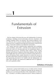
da/dN<br />
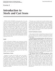
Plastic deformation<br />
envelope <strong>Crack</strong> tip<br />
Premature contact points<br />
Oxides<br />
Fig. 7 — <strong>Crack</strong><br />
closure<br />
mechanisms<br />
induced by:<br />
(a) plasticity,<br />
(b) roughness<br />
(c) oxide.<br />
Final failure<br />
Increasing<br />
Paris regime R<br />
Near threshold<br />
K<br />
Fig. 6 — Schematic representation of<br />
the R ratio effect on fatigue crack<br />
growth curves. The near threshold,<br />
Paris regime, and final failure<br />
regions are also indicated on the<br />
curves.<br />
<br />
<br />
Plastic zone<br />
(a)<br />
(b)<br />
(c)<br />
properties of the material, dimensions<br />
of the part, and<br />
loading conditions.<br />
The exact fraction of area of<br />
each region depends on the applied<br />
load level. High applied<br />
loads result in a small stable<br />
crack propagation area, as depicted<br />
in Fig. 4. On the other<br />
hand, if lower loads are applied,<br />
the crack will have to grow<br />
longer before the applied stress<br />
intensity factor K, reaches the<br />
fracture toughness value of the<br />
material, resulting in a smaller<br />
area of fast fracture, Fig. 4b.<br />
• Ratcheting marks: Ratcheting<br />
marks are another macroscopic<br />
feature that can be observed in<br />
fatigue fracture surfaces. These<br />
marks originate when multiple<br />
cracks, nucleated at different<br />
points, join together, creating<br />
steps on the fracture surface.<br />
Therefore, counting the number<br />
of ratchet marks is a good indication<br />
of the number of nucleation<br />
sites. Figure 5 presents in<br />
detail some ratchet marks found<br />
on the fracture surface of a large<br />
SAE 1045 rotating shaft fractured<br />
by fatigue.<br />
<strong>Propagation</strong> rates<br />
Similarly to the initiation phase,<br />
many factors can affect long fatigue<br />
crack propagation rates.<br />
Among them, special attention<br />
should be given to effects of load<br />
ratio and the presence of residual<br />
stresses.<br />
Increasing the load ratio has a<br />
tendency to increase the long<br />
crack growth rates in all regions<br />
of the curve plotting fatigue crack growth rate<br />
versus applied stress intensity factor range, or<br />
simply the curve of da/dN versus applied K. Generally<br />
the effect of increasing load ratio is less significant<br />
in the Paris regime than in near-threshold<br />
and near-failure regions, Fig. 6.<br />
Near the threshold stress intensity factor, Kth,<br />
K Keff<br />
(a ) Time<br />
(b) Time<br />
Fig. 8 — Load ratio effect on Keff, in a fatigue cycle: (a)<br />
KminKcl<br />
the effects of R ratio are mainly attributed to crackclosure<br />
effects, in which crack faces contact each<br />
other at an applied Kcl that is higher than the minimum<br />
applied stress intensity factor, Kmin.<br />
Several different mechanisms may contribute<br />
to premature crack closure. One consists of plasticity-induced<br />
closure, represented in Fig. 7a. As<br />
the crack grows, the material that has been previously<br />
permanently deformed within the plastic<br />
zone now forms an envelope of plastic zones in<br />
the wake of the crack front. This leads to displacements<br />
normal to the crack surfaces as the restraint<br />
is relieved. This is no problem while the crack is<br />
open; however as the load decreases, the crack<br />
surfaces touch before the minimum load is<br />
reached, shielding the crack. This type of premature<br />
contact can also occur due to crack wake<br />
roughness and irregularities, Fig. 7b, or by the<br />
presence of corrosion sub-products such as oxides,<br />
Fig. 7c.<br />
As observed in Fig. 8, the effect of closure produces<br />
a reduction in the effective K range because<br />
of the increase in the effective Kmin, reducing<br />
the driving force for fatigue crack growth. The effect<br />
is more significant near the threshold region<br />
because the crack tip opening displacements are<br />
smaller and crack faces are closer to each other.<br />
Additionally, for the same applied K, higher R<br />
ratios increase the applied values of Kmax and Kmin,<br />
increasing Keff.<br />
For most materials, the Paris regime is considered<br />
“closure-free and Kmax-independent” and the<br />
crack growth rates are generally very similar for<br />
tests conducted under different R ratios. Near the<br />
final failure, the effects of R ratio are related to the<br />
higher monotonic fracture component as Kmax approaches<br />
KIC.<br />
Therefore, for the same applied K, Kmax values<br />
are higher for tests conducted under higher applied<br />
R ratios, and consequently, da/dN values are<br />
higher.<br />
The effects of residual stress on fatigue crack<br />
growth are related to alterations in the R ratio and<br />
in the applied K. In other terms, the residual<br />
stresses affect the two parameters that control the<br />
crack driving force, i.e. Kmax and Keff. When a<br />
crack is introduced in a plate subjected to a<br />
residual stress field, a residual stress intensity<br />
factor Kr, arises that can either decrease or increase<br />
the crack driving force parameters.<br />
The superposition principle can also be applied<br />
40 ADVANCED MATERIALS & PROCESSES/MAY 2008<br />
Kap<br />
Kmax<br />
Kmin<br />
Kcl<br />
K<br />
Kap = Keff<br />
Kmax<br />
Kmin<br />
Kcl
This article is from<br />
Failure Analysis of Heat Treated Steel Components<br />
Edited by L.C.F. Canale, R.A. Mesquita, and G.E. Totten<br />
This thorough reference work discusses various causes of failure with integrated coverage of<br />
process metallurgy of steels by forging, casting, welding, and various heat treatment processes.<br />
The breadth of coverage and the numerous examples provide an invaluable resource for the designer,<br />
engineer, metallurgist, mechanical and materials engineers, quality control technicians,<br />
and heat treaters.<br />
For more information or to order, call Customer Service at 800/336-5152;<br />
or visit www.asminternational.org and click on the “<strong>ASM</strong> Store” button.<br />
in terms of the stress intensity factor, provided<br />
that the material remains linearly elastic. In this<br />
sense, Kr can be added to Kmax and Kmin:<br />
K’max = Kmax + Kr<br />
K’min = Kmin + Kr<br />
As a result, R’ and K’ are defined as follows:<br />
1. If K’min>0 then:<br />
mi.qxp 4/16/2008 8:57 AM Page 2<br />
K’ min = K min + Kr<br />
R’ = K’max K max + Kr<br />
K’ = K’max --K’min = (Kmax + Kr) -- (Kmin+ Kr) =<br />
Kmax --Kmin = K<br />
Of Material<br />
Interest<br />
REPRINTS<br />
CAN MAKE<br />
A BIG<br />
IMPACT<br />
For reprint inquiries and quotes please contact<br />
Diane Grubbs at 440/338-5151, ext. 5240<br />
diane.grubbs@asminternational.org<br />
T<br />
First steel-bodied school bus built in 1927<br />
he first steel-bodied “Within eight years, all major school bus<br />
school bus — “Blue Bird manufacturers were producing steel-body<br />
No. 1” — has been donated buses.”<br />
to The Henry Ford,<br />
Dearborn, Mich., by Blue By 1932 the Depression had reduced car sales<br />
Bird Corp., Fort Valley, Ga. so seriously that Luce sold his Ford agencies<br />
and concentrated full-time on manufacturing<br />
The bus was built by Albert school buses. He named his new company<br />
Luce Sr. in 1927. Luce was the Blue Bird Body Co. Today, Blue Bird Corp.<br />
owner of Ford dealerships in remains one of the nation’s major school bus<br />
Fort Valley and Perry, Ga., manufacturers.<br />
when one of his customers<br />
requested a vehicle to<br />
“Donating Blue Bird No. 1 to The Henry Ford at<br />
The first steel-bodied transport workers to a cement plant. Luce this time is meaningful to me for many<br />
school bus — Blue bought a wood-bodied bus, but the wood reasons,” says Albert L. “Buddy” Luce Jr., son<br />
Bird No. 1 — was deteriorated before the customer could finish of Albert Luce Sr. “Last year was [Blue Bird’s]<br />
built by Albert Luce paying for the vehicle. Luce investigated ways 80th anniversary, and I feel this is a great way<br />
Sr. in 1927 on a Ford of building a better bus and constructed a to acknowledge that milestone. In addition,<br />
Model T chassis. body using steel angles and channels, steel 2008 is the centennial of the Model T Ford.<br />
Luce’s son, Albert Jr., sheets, wood, and canvas. He then mounted it Blue Bird No. 1 will be a valuable addition to<br />
donated it to The to a 1927 Ford Model T chassis. He sold the the collection of this great institution.” The bus<br />
Henry Ford in new bus to Frank Slade of Marshallville, Ga., to went on display in Henry Ford Museum this<br />
Dearborn, Mich., be used as a school bus.<br />
month.<br />
where it is now on<br />
display. “By taking one innovation, the Model T, and The Henry Ford was founded in 1929 by the<br />
using it as the foundation for his school bus, automotive pioneer. It includes Henry Ford<br />
Mr. Luce changed the paradigm of<br />
Museum, Greenfield Village, the Henry Ford<br />
transportation for school-age children in terms IMAX Theatre, the Benson Ford Research<br />
of safety and reliability, says Patricia<br />
Center, and the Ford Rouge Factory Tour. For<br />
Mooradian, president of The Henry Ford. more information, visit www.thehenryford.org.<br />
Theater stage builders know During production of the section, the natural<br />
only too well that transporting flax fiber mats are first impregnated on both<br />
and assembling heavy stage sides with the dual-component polyurethane<br />
sections can quickly become system using a spray process. The mats and<br />
a pain — quite literally. Yet the expanded polystyrene (EPS) core are then<br />
back complaints resulting assembled to form a sandwich and inserted<br />
from heavy lifting could soon into a preheated mold. This layered structure is<br />
be a thing of the past thanks pressed into the desired shape at<br />
to lightweight stage sections temperatures normally ranging from 60 to<br />
developed by Triple-E<br />
120°C (140 to 250°F) and pressures between 6<br />
Lichtgewicht Meubilair B.V., and 8 bar (85 and 115 psi), and cures within a<br />
Lightweight, sturdy, Winsum, Netherlands. Triple-E’s Flax-Deck matter of minutes. No post-treatment of the<br />
easy-to-store stage sections have external dimensions of 0.75 by sandwich composite by annealing, for<br />
sections are made by 1.50 m (2.5 by 5 ft) and weigh just 16.5 kg (36 example, is necessary.<br />
the Dutch company lb). The low weight of the stackable and<br />
Triple-E Lichtgewicht compact sections is due to their composite Compression molding opens up yet more<br />
Meubilair using sandwich construction based on the Baypreg design options for sandwich technology using<br />
composite sandwich polyurethane spray system from Bayer<br />
Baypreg, says Bayer. Curves and changes in<br />
construction based MaterialScience, Leverkusen, Germany. wall thickness are also possible, for example.<br />
on a Bayer<br />
This feature was used to create recesses on<br />
MaterialScience The versatile stage sections consist of a light the bottom of the stage sections into which<br />
polyurethane spray rigid foam core reinforced top and bottom with the folded-up aluminum legs are stowed.<br />
system. flax mats to absorb tensile forces, thereby The sections can thus be stored by stacking on<br />
increasing the strength of the composite top of one another in a minimum of space,<br />
material, explains Bayer. The sandwich<br />
without damaging their surfaces.<br />
structure can withstand a concentrated load of<br />
up to 150 kgf (330 lbf). Its surface is<br />
Bayer MaterialScience is a Bayer Group<br />
protected by an abrasion-resistant plastic company. For more information, visit<br />
layer that is available in various colors.<br />
www.bayermaterialscience.com. There’s also<br />
Foldaway and height-adjustable aluminum a fax hotline for reader inquiries:<br />
legs are mounted underneath.<br />
+49 221 9902 160.<br />
Lightening the load for the stage crew<br />
ELECTROLESS NICKEL<br />
COMPOSITE COATINGS<br />
Electroless nickel coatings reinforced<br />
with diamond, silicon carbide, boron<br />
nitride, or PTFE particles can impart<br />
specific wear and lubricity properties<br />
to complex surfaces.<br />
Lloyd Ploof*<br />
Sirius Technology, Inc.<br />
Oriskany, New York<br />
lectroless nickel is an alloy of nickel and phosphorus.<br />
It is an autocatalytic coating, which<br />
simply means it will deposit from solution on<br />
certain substrates without any external source Eof<br />
electricity. Electroless nickel coatings are<br />
produced by the controlled chemical reduction<br />
of nickel ions onto a catalytic surface.<br />
The reaction continues as long as the<br />
surface remains in contact with the electroless<br />
nickel solution. Because the deposit<br />
is applied without an electric current,<br />
its thickness is uniform on all areas<br />
in contact with fresh solution.<br />
All electroless nickel coatings have the<br />
Fig. 1 — 1000X cross<br />
distinct advantage of being able to alternatives.<br />
section photomicrograph of a<br />
EN/diamond coating with evenly coat the substrate, both inside<br />
2 m diamond particles. and out, as long as the solution flows<br />
uniformly. Electrolytic coatings, vapor<br />
coatings, and thermal-spray coatings<br />
typically cannot achieve uniform<br />
coating thicknesses across a broad range<br />
of part geometry. With some of these<br />
methods, a final 0.0005 inch thickness<br />
on a part interior may require depositing<br />
0.001 inch or more on the exterior.<br />
Fig. 2 — Cross<br />
section of Others cannot deposit on the interior of parts at<br />
EN/PTFE all. This can be a major cost advantage for elec-<br />
deposit. troless nickel coatings, and also makes it the only<br />
real choice in certain applications.<br />
Electroless nickel plating can be divided into<br />
three main types: low phosphorus (1 to 4 wt.% P),<br />
*Member of <strong>ASM</strong> <strong>International</strong><br />
Table 1 — Properties of non-composite electroless nickels<br />
8 ADVANCED MATERIALS & PROCESSES/MAY 2008<br />
mid phosphorus (4 to 10 wt% P), and high phosphorus<br />
(>10.5 wt% P). Without the composite element,<br />
each subset has distinct uses and properties.<br />
Some properties of non-composite<br />
electroless nickels are presented in Table 1.<br />
This article will examine the performance and<br />
cost advantages possible with electroless nickel<br />
composite coatings. It will focus on four specific<br />
types of composite electroless nickels: diamond,<br />
silicon carbide, boron nitride, and polytetrafluoroethylene<br />
(PTFE).<br />
Composite electroless nickel<br />
Composite electroless nickels are defined as<br />
those that incorporate distinct particles into the<br />
deposit to impart a specific property. Figure 1 is<br />
a photomicrograph of a typical EN/Diamond<br />
composite coating that displays the incorporated<br />
diamond particles. Figure 2 is a photomicrograph<br />
of an EN/PTFE deposit. As you can see, the functional<br />
particles are evenly and thoroughly distributed<br />
in the EN matrix, which is firmly bonded to<br />
the substrate. This unique combination of distribution<br />
and bond strength makes composite EN<br />
coatings extremely long lasting and durable compared<br />
with many other wear and lubrication<br />
Theoretically, almost any type of particle could<br />
be co-deposited, as long as it could withstand the<br />
conditions within an EN bath, and if it were of the<br />
appropriate size. Since this article is concerned<br />
with wear and lubricity, only the four most widely<br />
used EN composites will be considered.<br />
Improvements in wear resistance<br />
Generally speaking, diamond and silicon carbide<br />
electroless nickel composite coatings are<br />
chosen for wear resistance. Boron nitride and<br />
PTFE composite coatings are selected for lubricity.<br />
However, depending on the application,<br />
any of these coatings might improve wear resistance<br />
or lubricity, as the mechanisms for<br />
failure or success can be similar in both cases,<br />
depending on the type of wear. Wear resistance<br />
Corrosion Hardness<br />
resistance, after<br />
Phosphorus, neutral Taber wear*, Type of Hardness as 1 hr bake<br />
wt% salt spray as plated stress plated, Rc at 725 Plating type o F, Rc Structure<br />
Low phosphorus 1-4 Moderate 6-15 Tensile 53-63 60-70 Crystalline<br />
Mid phosphorus 4-10 Moderate 14-19<br />
or Compressive<br />
Tensile 44-49 59-67 Crystalline<br />
High phosphorus 10.5-14 Very good 20-35 Compressive 42-48 60-69 Amorphous<br />
*milligrams loss per 1000 cycles, load of 10N, CS-10 wheel<br />
36 ADVANCED MATERIALS & PROCESSES/MAY 2008<br />
Reliable materials for deep well<br />
construction must have high<br />
strength and corrosion resistance at<br />
high temperatures.<br />
Bruce Craig*<br />
MetCorr<br />
Denver, Colorado<br />
he increasing worldwide demand for oil<br />
and gas coupled with the fact that the<br />
peak of oil production has been reached<br />
or soon will be, has pushed the petroleum<br />
industry into drilling ever deeper wells. Well<br />
depths of 25,000 ft (7620 m) and greater are no<br />
longer unusual, and even deeper wells are<br />
expected.<br />
Generally, increasing depth means increasing<br />
pressure and temperature. High-pressure/hightemperature<br />
(HPHT) wells have generally been<br />
considered wells in which temperatures and pressures<br />
at the bottom of the well exceed 300 to 350°F<br />
(149 to 177°C) and 10,000 psi (69 MPa), respectively.<br />
Many HPHT wells have already been<br />
drilled and completed in this category with great<br />
success and no unusual requirements for special<br />
materials.<br />
Figure 1 illustrates some of these successful<br />
field applications, in addition to more recent<br />
activity in East Texas and the Gulf of Mexico.<br />
The industry has had to pursue ever more hostile<br />
conditions than the original HPHT limits<br />
stated above to keep up with demand. In this<br />
case, conditions exceeding 400°F (204°C) and<br />
20,000 psi (138 MPa) at bottomhole have been<br />
labeled variously as Extreme HPHT (xHPHT)<br />
and Ultra HPHT. (The term HPHT is used<br />
throughout this article to include both extreme<br />
and ultra.)<br />
This is where challenges will be for both the<br />
materials themselves and materials engineers Liners, tubing, and strings<br />
in the petroleum industry for the future. Drilling Figure 2 shows a typical well completion for<br />
these HPHT wells requires specialized methods those unfamiliar with the industry terminology.<br />
and considerable planning, but the materials have Surface casing and some of the intermediate<br />
largely remained steel drill pipe and steel com- casing strings are not affected by HPHT condiponents,<br />
although other alloys such as titanium tions, and thus standard steel tubulars function<br />
are being considered.<br />
well.<br />
However, the real materials challenges are in The major components that require greater at-<br />
completing and producing the wells after they tention and represent materials challenges are the<br />
are drilled. This is the reason this article focuses liner at the bottom of the well, the tieback casing<br />
on well construction rather than drilling. string, the tubing (and associated jewelry), and<br />
the Christmas tree, which is not shown but com-<br />
ADVANCED MATERIALS & PROCESSES/MAY 2008 33<br />
T<br />
*Member of <strong>ASM</strong> <strong>International</strong><br />
MATERIALS FOR<br />
DEEP OIL AND GAS WELL<br />
CONSTRUCTION<br />
POWERING THE FUTURE<br />
Drilling rig at sunset.<br />
Initial rreservoir pressure, MPa<br />
69 83 97 110 124 138<br />
525<br />
(274)<br />
475<br />
(246) Madden<br />
Deep<br />
East Texas<br />
425<br />
(219)<br />
Shearwater<br />
Mobile BBay<br />
Mary Ann Thomasville<br />
375<br />
Franklin<br />
(190)<br />
Erskine<br />
Elgin<br />
New Gulf of<br />
Mexico<br />
325<br />
Villa/Trecate<br />
(163)<br />
Fields<br />
Embla<br />
Malossa<br />
10 12 14 16 18 20<br />
Initial rreservoir pressure, ksi<br />
<br />
<br />
<br />
<br />
<br />
<br />
<br />
<br />
<br />
<br />
Reservoir temperature, °F ((°C)<br />
Fig. 1 — Some of the prominent HPHT fields in the world.<br />
Updated from Ref. 1.<br />
2. If K’min