Understanding takeoff speeds - Airbus
Understanding takeoff speeds - Airbus
Understanding takeoff speeds - Airbus

You also want an ePaper? Increase the reach of your titles
YUMPU automatically turns print PDFs into web optimized ePapers that Google loves.
Flight Operations Briefing Notes<br />
I Introduction<br />
Takeoff and Departure Operations<br />
<strong>Understanding</strong> Takeoff Speeds<br />
Flight Operations Briefing Notes<br />
Takeoff and Departure Operations<br />
<strong>Understanding</strong> Takeoff Speeds<br />
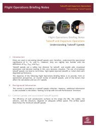
Pilots are used to calculating <strong>takeoff</strong> <strong>speeds</strong> and, therefore, understand the operational<br />
significance of V1, VR, and V2. However, they are slightly less familiar with the<br />
definitions of VMU, VMCG, and VMCA..<br />
Takeoff <strong>speeds</strong> are a safety key element for <strong>takeoff</strong>, and enable pilot situational<br />
awareness and decision-making in this very dynamic situation. The use of erroneous<br />
<strong>takeoff</strong> <strong>speeds</strong> can lead to tail strikes, high-speed rejected <strong>takeoff</strong>s or initial climb with<br />
degraded performance.<br />
The objective of the following Flight Operations Briefing Notes is to provide, from an<br />
operational perspective, an overall review of <strong>takeoff</strong> <strong>speeds</strong>, and of the factors that<br />
affect the calculation and use of V <strong>speeds</strong>.<br />
II Background Information<br />
This section is provided as a <strong>takeoff</strong> <strong>speeds</strong> refresher. However, additional information<br />
is also available in the <strong>Airbus</strong> “Getting to Grips with Aircraft Performance” brochure.<br />
II.1 Control Speeds and associated Takeoff Speeds<br />
The efficiency of such aerodynamic surfaces as the wings (for lift), the rudder, the<br />
ailerons, and the elevators, depends on adequate airflow speed. This airflow speed<br />
determines the minimum <strong>takeoff</strong> <strong>speeds</strong>.<br />
Page 1 of 8
Flight Operations Briefing Notes<br />
VMCG (Velocity of Minimum Control on Ground)<br />
Takeoff and Departure Operations<br />
<strong>Understanding</strong> Takeoff Speeds<br />
During the <strong>takeoff</strong> roll, it is of utmost importance to know the minimum speed at which<br />
the aircraft will remain controllable, in the event of an engine failure on ground. This is<br />
because, in such a case, and if the <strong>takeoff</strong> is continued, only the rudder will be able to<br />
counteract the yaw moment that is generated by asymmetric engine(s) thrust.<br />
Per regulations, the minimum speed at which an aircraft is defined to be “controllable”<br />
(lateral excursion lower than 30 feet) after an engine failure on ground, is referred to<br />
as V MCG (Velocity of Minimum Control on Ground) .<br />
VMCG mainly depends on:<br />
− Engine(s) thrust<br />
− Pressure altitude.<br />
If a failure occurs before reaching VMCG, the <strong>takeoff</strong> must be interrupted to maintain<br />
control of the aircraft.<br />
Note: Steering is not used during certification flight tests. However, in real life<br />
operations, steering would be helpful in controlling the aircraft.<br />
V1: Decision Speed<br />
Figure 1<br />
Ground Control after Engine Failure<br />
V1 is the maximum speed at which a rejected <strong>takeoff</strong> can be initiated, in the event of an<br />
emergency. Additional information on this “Go/No-Go” decision can be found in the<br />
Flight Operations Briefing Note entitled: “Revisiting the Stop or Go Decision”.<br />
V1 is also the minimum speed at which a pilot can continue a <strong>takeoff</strong> after an engine<br />
failure.<br />
If an engine failure is detected after V1, the <strong>takeoff</strong> must be continued. This implies that<br />
the aircraft must be controllable on ground. Therefore, V1 is always greater than VMCG.<br />
Page 2 of 8
Flight Operations Briefing Notes<br />
VMU (Velocity of Minimum Unstick)<br />
Takeoff and Departure Operations<br />
<strong>Understanding</strong> Takeoff Speeds<br />
V MU is achieved by pitching the aircraft up to the maximum (tail on the runway, for<br />
aircraft that are are geometrically-limited) during the <strong>takeoff</strong> roll (Refer to Figure 2<br />
below). The speed at which the aircraft first lifts off is V MU. Therefore, lift-off is not<br />
possible prior to VMU.<br />
Note: All <strong>Airbus</strong> aircraft types, with the exception of the A318, are geometricallylimited.<br />
VR : Rotation Speed<br />
Figure 2<br />
VMU Flight Test on an A330<br />
The rotation speed ensures that, in the case of an engine failure, lift-off is possible and<br />
V2 is reached at 35 feet at the latest.<br />
Note: Therefore, at 35 feet, the actual speed is usually greater than V2.<br />
The rotation of the aircraft begins at VR, which makes lift-off possible, at the end of the<br />
maneuver.<br />
The VR must be such that the lift-off speed is greater than VMU.<br />
Page 3 of 8
Flight Operations Briefing Notes<br />
VMCA (Velocity of Minimum Control in the Air)<br />
Takeoff and Departure Operations<br />
<strong>Understanding</strong> Takeoff Speeds<br />
The rudder is used to compensate for the yaw moment caused by thrust asymmetry.<br />
There is a minimum speed at which full rudder will be necessary, in order to fly a<br />
constant heading with level wings.<br />
Figure 3<br />
Sideslip Angle in a One Engine-out Condition<br />
To reduce sideslip, this speed can be reduced even more, if the aircraft is banked on<br />
the live engine’s side.<br />
The lower the speed, the greater the necessary bank angle. The speed that corresponds<br />
to a 5-degree bank angle is defined, by regulations, as the minimum control speed and<br />
is referred to as V MCA (Velocity of Minimum Control in the Air) .<br />
V2: Takeoff Safety Speed<br />
Figure 4<br />
Roll Angle at VMCA<br />
V2 is the minimum speed that needs to be maintained up to acceleration altitude, in the<br />
event of an engine failure after V1. Flight at V2 ensures that the minimum required<br />
climb gradient is achieved, and that the aircraft is controllable. V2 speed is always<br />
greater than VMCA, and facilitates control of the aircraft in flight.<br />
In an all-engines operative <strong>takeoff</strong>, V2+10 provides a better climb performance than V2<br />
(Refer to Figure 5 below).<br />
Page 4 of 8
Flight Operations Briefing Notes<br />
Figure 5<br />
Takeoff and Departure Operations<br />
Climb Gradient Relative to Speed in a Specific Flaps’ Configuration<br />
If one engine is lost before reaching V2, then the initial climb is flown at V2.<br />
<strong>Understanding</strong> Takeoff Speeds<br />
If thrust is lost at a speed between V2 and V2+10, then the current speed is maintained,<br />
to ensure the most efficient climb speed.<br />
It is not necessary to increase pitch, in order to reduce the speed to V2, when a higher<br />
speed has already been reached.<br />
II.2 Minimum Control Speeds with Derated Thrust<br />
“JAR/FAR: AMJ 25-13 / AC 25-13<br />
(4)(b) Derated <strong>takeoff</strong> thrust, for an aeroplane, is a <strong>takeoff</strong> thrust less than the<br />
maximum <strong>takeoff</strong> thrust, for which exists in the AFM a set of separate and independent<br />
<strong>takeoff</strong> limitations and performance data that complies with all requirements of<br />
Part 25.”<br />
A specific derate level corresponds to the basic maximum thrust that is reduced by a<br />
corresponding percentage value. New minimum control <strong>speeds</strong> (VMCG, VMCA) can then be<br />
established.<br />
Reducing the minimum control <strong>speeds</strong> sometimes improves <strong>takeoff</strong> performance<br />
(higher MTOW), when taking off on a short runway. Indeed, the V1 decision speed is the<br />
maximum speed at which it is still possible to reject the <strong>takeoff</strong> and stop the aircraft<br />
within the runway limits. Nevertheless, V1 must be greater than VMCG, and the<br />
“Accelerate-Stop Distance” is often the most constraining limitation on a short runway.<br />
A reduction in VMCG then permits a reduction in the ASD for a specific <strong>takeoff</strong> weight,<br />
and can improve <strong>takeoff</strong> performance when the MTOW (without derate) is ASD/VMCGlimited.<br />
Page 5 of 8
Flight Operations Briefing Notes<br />
Takeoff and Departure Operations<br />
<strong>Understanding</strong> Takeoff Speeds<br />
For a derated <strong>takeoff</strong>, the limitations, the procedures, and the performance data must<br />
be included in the Aircraft Flight Manual (AFM). For each derate level, a specific RTOW<br />
chart can be defined for a each runway, in order to take into account such new<br />
limitations as minimum control <strong>speeds</strong>.<br />
Note:<br />
The objective of flexible thrust differs from that of derated thrust. Both types of thrust<br />
cannot be used interchangeably.<br />
Flexible Thrust is a thrust reduction, designed to save engine life. This thrust is reduced<br />
to take advantage of the available runway length, when full thrust is not necessary<br />
(from a performance perspective), but <strong>takeoff</strong> <strong>speeds</strong> with full thrust still apply.<br />
III Operational and Human Factors Affecting Takeoff Speed Computation<br />
and Utilization<br />
The following factors are often observed when analyzing <strong>takeoff</strong>s in which <strong>takeoff</strong><br />
<strong>speeds</strong> were not respected. Two cases can be observed:<br />
III.1 Error in Takeoff Speed Computation:<br />
• Data, issued from a computerized system, is rarely challenged. However, incorrect<br />
inputs may occur, and could result in inadequate <strong>takeoff</strong> <strong>speeds</strong> values.<br />
• In <strong>takeoff</strong> speed calculations, Zero Fuel Weight (ZFW) is sometimes mistaken for<br />
Gross Weight (GW). This is particularly true when a last minute change occurs in<br />
cargo loading, or when time pressure and workload are high. Therefore, calculated<br />
<strong>speeds</strong> will be much lower than expected, and will lead to: Tailstrikes, “heavy<br />
aircraft” sensation, and high-speed rejected <strong>takeoff</strong>s.<br />
• Takeoff <strong>speeds</strong> calculations are based on specific configurations. Any change in the<br />
parameters of these configurations will invalidate <strong>takeoff</strong> <strong>speeds</strong>. Examples of such<br />
parameters include a runway change, a wet runway that becomes contaminated, or<br />
a <strong>takeoff</strong> from an intersection.<br />
III.2 Error in Takeoff Speed Utilization:<br />
• When a last minute-change occurs, <strong>takeoff</strong> <strong>speeds</strong> are sometimes modified and<br />
crosschecked during pushback or taxi. During such phases of flight, the PF workload<br />
is high. As a result the PF may not have sufficient time or resources to perform<br />
efficient crosschecks.<br />
• If an incident occurs before V1, the PNF’s attention may be focused on trying to<br />
assess the situation and may forget the V1 announcement.<br />
Page 6 of 8
Flight Operations Briefing Notes<br />
Takeoff and Departure Operations<br />
<strong>Understanding</strong> Takeoff Speeds<br />
• In the event of an engine failure after <strong>takeoff</strong>, and in an attempt to climb faster,<br />
there may be a tendency to set a pitch attitude too high, if FD bars are not followed.<br />
The aircraft is then flown below V2, and climb performance cannot be ensured, as<br />
illustrated in Figure 5.<br />
IV Prevention Strategies and Lines of Defense<br />
The following strategies help to prevent <strong>takeoff</strong> speed errors. Airlines should:<br />
• Define and use good CRM practices for <strong>takeoff</strong> speed computation and crosscheck.<br />
• Conduct a <strong>takeoff</strong> briefing that highlights <strong>takeoff</strong> <strong>speeds</strong>, slats/flaps configurations,<br />
and weight, depending on the daily weather conditions. Attention should be paid to<br />
<strong>takeoff</strong> <strong>speeds</strong>, particularly if they were changed during taxi, in order to detect<br />
possible keystroke errors.<br />
• For aircraft that are not equipped with a V1 auto-callout: close attention to the V1<br />
standard callout should be paid.<br />
• Emphasize that, once airborne, pilots should always follow the Flight Director’s pitch<br />
guidance bar and should consider using the autopilot in the event of an engine<br />
failure. This will considerably reduce the flight crew’s workload during demanding<br />
flight phase situations.<br />
V Summary of Keypoints<br />
Takeoff speed calculation errors are often due to a combination of two factors:<br />
• Error in parameter entry<br />
• Poor crosschecks by other crewmember.<br />
Prevention strategies should be developed to ensure efficient crosschecks, particularly<br />
after last-minute changes (runway change, loadsheet modification…).<br />
VI Associated Flight Operations Briefing Notes<br />
The following Flight Operations Briefing Notes should be reviewed along with the above<br />
information:<br />
• Conducting Effective Briefings<br />
• Preventing Tailstrike at Takeoff<br />
• Revisiting the “Stop or Go” Decision<br />
• Preventing Runway Excursions and Overruns at Takeoff<br />
Page 7 of 8
Flight Operations Briefing Notes<br />
VII Regulatory References<br />
• JAR/FAR 25.107 Subpart B – Takeoff Speeds<br />
VIII <strong>Airbus</strong> References<br />
Takeoff and Departure Operations<br />
<strong>Understanding</strong> Takeoff Speeds<br />
The following <strong>Airbus</strong> brochure provides more performance-oriented information<br />
concerning <strong>takeoff</strong> <strong>speeds</strong>:<br />
• “Getting To Grips with Aircraft Performance”<br />
IX Additional Reading Material<br />
Example of events linked to <strong>takeoff</strong> <strong>speeds</strong> are available in the following documents:<br />
• Transportation Safety Board of Canada – 2002 Air Investigation Reports – 14 June<br />
2002 (www.tsb.gc.ca/en/reports/air/2002)<br />
• National Transportation Safety Board – NTSB accident number: NYC91FA086<br />
(http://www.ntsb.gov/)<br />
• Flight Safety Foundation – Accident prevention – May 1995<br />
• Flight Safety Foundation – Accident prevention – May 1996<br />
Note:<br />
These documents can be found on the Flight Safety Foundation website:<br />
http://www.flightsafety.org/home.html.<br />
This FOBN is part of a set of Flight Operations Briefing Notes that provide an overview of the applicable standards,<br />
flying techniques and best practices, operational and human factors, suggested company prevention strategies and personal<br />
lines-of-defense related to major threats and hazards to flight operations safety.<br />
This FOBN is intended to enhance the reader's flight safety awareness but it shall not supersede the applicable regulations<br />
and the <strong>Airbus</strong> or airline's operational documentation; should any deviation appear between this FOBN and the <strong>Airbus</strong> or<br />
airline’s AFM / (M)MEL / FCOM / QRH / FCTM, the latter shall prevail at all times.<br />
In the interest of aviation safety, this FOBN may be reproduced in whole or in part - in all media - or translated; any use of<br />
this FOBN shall not modify its contents or alter an excerpt from its original context. Any commercial use is strictly excluded.<br />
All uses shall credit <strong>Airbus</strong>.<br />
<strong>Airbus</strong> shall have no liability or responsibility for the use of this FOBN, the correctness of the duplication, adaptation or<br />
translation and for the updating and revision of any duplicated version.<br />
<strong>Airbus</strong> Customer Services<br />
Flight Operations Support and Line Assistance<br />
1 Rond Point Maurice Bellonte - 31707 BLAGNAC CEDEX FRANCE<br />
FOBN Reference : FLT_OPS – TOFF_DEP – SEQ 07 – REV 01 – AUG. 2004<br />
Page 8 of 8