LTC Repair Lombardini Engine Troubleshooting - Wacker Neuson
LTC Repair Lombardini Engine Troubleshooting - Wacker Neuson
LTC Repair Lombardini Engine Troubleshooting - Wacker Neuson

Create successful ePaper yourself
Turn your PDF publications into a flip-book with our unique Google optimized e-Paper software.
www.wackergroup.com<br />
REPAIR MANUAL<br />
0 1 6 3 7 2 2 E N<br />
Light Tower<br />
<strong>LTC</strong> 4<br />
0163722en 001<br />
0910
<strong>LTC</strong> <strong>Repair</strong> Foreword<br />
This manual covers the following machines:<br />
Item No. Revisions Covered<br />
0009377 105 and higher<br />
0009379 104 and higher<br />
0009485 104 and higher<br />
Operating / Parts Information<br />
You must be familiar with the operation of this machine before you<br />
attempt to troubleshoot or repair it. Basic operating and maintenance<br />
procedures are described in the Operator’s Manual supplied with the<br />
machine. Keep a copy of the Operator’s Manual with the machine at all<br />
times. Use the separate Parts Book supplied with the machine to order<br />
replacement parts. If you are missing either of the documents, please<br />
contact <strong>Wacker</strong> Corporation to order a replacement.<br />
Damage caused by misuse or neglect of the unit should be brought to<br />
the attention of the operator to prevent similar occurrences from<br />
happening in the future.<br />
This manual provides information and procedures to safely repair and<br />
maintain the above <strong>Wacker</strong> model(s). For your own safety and<br />
protection from injury, carefully read, understand, and observe all<br />
instructions described in this manual. THE INFORMATION<br />
CONTAINED IN THIS MANUAL IS BASED ON MACHINES<br />
MANUFACTURED UP TO THE TIME OF PUBLICATION. WACKER<br />
CORPORATION RESERVES THE RIGHT TO CHANGE ANY<br />
PORTION OF THIS INFORMATION WITHOUT NOTICE.<br />
3
Foreword <strong>LTC</strong> <strong>Repair</strong><br />
WARNING<br />
4<br />
CALIFORNIA<br />
Proposition 65 Warning:<br />
Diesel engine exhaust, some of its constituents, and certain vehicle<br />
components contain or emit chemicals known to the State of California<br />
to cause cancer and birth defects or other reproductive harm.<br />
All rights, especially copying and distribution rights, are reserved.<br />
Copyright 2007 by <strong>Wacker</strong> Corporation<br />
No part of this publication may be reproduced in any form or by any<br />
means, electronic or mechanical, including photocopying, without<br />
express written permission from <strong>Wacker</strong> Corporation.<br />
Any type of reproduction or distribution not authorized by <strong>Wacker</strong><br />
Corporation represents an infringement of valid copyrights, and<br />
violators will be prosecuted. We expressly reserve the right to make<br />
technical modifications, even without due notice, which aim at<br />
improving our machines or their safety standards.
<strong>LTC</strong> <strong>Repair</strong> Table of Contents<br />
1. Safety Information 9<br />
1.1 Laws Pertaining to Spark Arresters ...................................................... 9<br />
1.2 Operating Safety ................................................................................ 10<br />
1.3 Operator Safety while using Internal Combustion <strong>Engine</strong>s ................ 11<br />
1.4 Towing Safety ..................................................................................... 12<br />
1.5 Service Safety .................................................................................... 13<br />
1.6 Label Locations .................................................................................. 14<br />
1.7 Safety and Operating Labels .............................................................. 16<br />
2. Technical Data 22<br />
2.1 <strong>Engine</strong> ................................................................................................ 22<br />
2.2 Generator ........................................................................................... 24<br />
2.3 Machine .............................................................................................. 25<br />
3. Operation 27<br />
3.1 Information Regarding Operation ....................................................... 27<br />
3.2 Locating Trailer ................................................................................... 27<br />
3.3 Leveling Trailer ................................................................................... 28<br />
3.4 Adjusting Lights .................................................................................. 28<br />
3.5 Preparing Trailer for Towing or Lifting ................................................ 29<br />
3.6 Raising Tower (Manual Winch System) ............................................. 30<br />
3.7 Lowering Tower (Manual Winch System) ........................................... 32<br />
3.8 Control Panels—Item 0009377 .......................................................... 34<br />
3.9 Control Panels—Items 0009379 and 0009485 .................................. 35<br />
3.10 Starting ............................................................................................... 36<br />
3.11 Automatic Shutdown .......................................................................... 36<br />
3.12 Operating Lights ................................................................................. 37<br />
3.13 Stopping ............................................................................................. 37<br />
3.14 Receptacles—50 Hz ........................................................................... 37<br />
4. Maintenance 38<br />
4.1 Periodic Maintenance Schedule ......................................................... 38<br />
4.2 Daily Inspection .................................................................................. 39<br />
4.3 Installing / Removing Light Fixtures ................................................... 40<br />
5
Table of Contents <strong>LTC</strong> <strong>Repair</strong><br />
4.4 Precautions When Replacing / Removing Bulbs .................................41<br />
4.5 Replacing Bulbs ..................................................................................42<br />
4.6 Air Cleaner ..........................................................................................43<br />
4.7 <strong>Engine</strong> Oil ............................................................................................43<br />
4.8 <strong>Lombardini</strong> <strong>Engine</strong> Wiring ...................................................................44<br />
4.9 <strong>Engine</strong> Wiring Components .................................................................45<br />
4.10 <strong>Engine</strong> Control Panel Internal Wiring—<strong>Lombardini</strong> .............................46<br />
4.11 <strong>Engine</strong> Control Panel Components—<strong>Lombardini</strong> ................................47<br />
4.12 Wiring Diagram: 50Hz 230V 0009377 .................................................48<br />
4.13 Components: 50Hz 230V 0009377 .....................................................49<br />
4.14 Wiring Diagram: 50Hz 115V 0009379 .................................................50<br />
4.15 Components: 50Hz 115V 0009379 .................................................... 51<br />
4.16 Wiring Diagram: 50 Hz 230V 0009485 ................................................52<br />
4.17 Components: 50Hz 230V 0009485 .....................................................53<br />
4.18 Generator Capacitor Excitation Schematic .........................................54<br />
4.19 Trailer Wiring .......................................................................................55<br />
5. <strong>Lombardini</strong> <strong>Engine</strong> <strong>Troubleshooting</strong> 56<br />
5.1 <strong>Troubleshooting</strong> Flowcharts ................................................................56<br />
5.2 <strong>Engine</strong> Does Not Crank—Flowchart 3A ..............................................57<br />
5.3 Checking Keyswitch and Wiring ..........................................................58<br />
5.4 Replacing Keyswitch ...........................................................................60<br />
5.5 <strong>Engine</strong> Cranks But Does Not Start—Flowchart 4A .............................61<br />
5.6 Checking Fuel System ........................................................................62<br />
5.7 Checking Voltage to Glow Plugs (<strong>Lombardini</strong> 1003 engines) .............63<br />
5.8 Checking Glow Plug Relay ..................................................................64<br />
5.9 Replacing Glow Plug Relay .................................................................64<br />
5.10 Checking Glow Plugs ..........................................................................65<br />
5.11 <strong>Engine</strong> Shuts Down—Flowchart 5A ....................................................66<br />
5.12 Checking Oil Pressure and Coolant Temperature Switches ...............67<br />
5.13 General <strong>Engine</strong> <strong>Troubleshooting</strong> .........................................................68<br />
6. Electrical <strong>Troubleshooting</strong> Procedures 72<br />
6.1 <strong>Troubleshooting</strong> Methodology .............................................................72<br />
6.2 Checking Continuity ............................................................................73<br />
6.3 Checking resistance ............................................................................73<br />
6.4 Checking voltage .................................................................................73<br />
wc_br0163722en_001TOC.fm 6
<strong>LTC</strong> <strong>Repair</strong> Table of Contents<br />
6.5 <strong>Troubleshooting</strong> Flowcharts ............................................................... 74<br />
6.6 Lights do not Illuminate—Flowchart 1A .............................................. 75<br />
6.7 Checking <strong>Engine</strong> Speed ..................................................................... 76<br />
6.8 Checking Generator Voltage at the Short Terminal Strip ................... 78<br />
6.9 Lights Do Not Illuminate—Flowchart 1B ............................................. 80<br />
6.10 Checking the Stator Windings ............................................................ 82<br />
6.11 Checking the Excitation Winding ........................................................ 84<br />
6.12 Checking the Excitation Capacitor ..................................................... 86<br />
6.13 Flashing the Generator ....................................................................... 88<br />
6.14 Removing the Generator .................................................................... 90<br />
6.15 Installing the Generator ...................................................................... 92<br />
6.16 Checking the Rotor Diodes ................................................................ 94<br />
6.17 Checking the Rotor Windings ............................................................. 96<br />
6.18 Lights do not Illuminate—Flowchart 1C .............................................. 97<br />
6.19 Checking Voltage at the Main Circuit Breaker .................................... 98<br />
6.20 Checking Voltage to Long Terminal Strip ......................................... 100<br />
6.21 Checking Individual Circuit Breakers ................................................ 102<br />
6.22 Confirming a Malfunctioning Circuit Breaker .................................... 104<br />
6.23 Checking Incoming Voltage to Ballast Capacitor(s) ......................... 106<br />
6.24 Checking Outgoing Voltage from Ballast Capacitor(s) ..................... 108<br />
6.25 Confirming a Faulty Ballast Capacitor .............................................. 110<br />
6.26 Checking Wiring to/from Ballast Transformers ................................. 112<br />
6.27 Replacing Ballast Transformer(s) ..................................................... 114<br />
6.28 Checking Voltage at the Receptacle ................................................ 116<br />
6.29 Checking Receptacle’s Circuit Breaker ............................................ 118<br />
6.30 Checking the Emergency Stop Switch ............................................. 119<br />
6.31 <strong>Troubleshooting</strong> the Power Winch ................................................... 120<br />
7. Disassembly/Assembly Procedures 123<br />
7.1 Tools ................................................................................................. 123<br />
7.2 Ordering Parts .................................................................................. 123<br />
7.3 Reference Numbers ( ) ..................................................................... 123<br />
7.4 Weight Block .................................................................................... 123<br />
7.5 Light Assembly ................................................................................. 124<br />
7.6 Tower Assembly Exploded View ...................................................... 126<br />
7.7 Tower Assembly List of Parts ........................................................... 127<br />
7.8 Upper Mast ....................................................................................... 127<br />
7.9 Mid Mast ........................................................................................... 130<br />
7.10 Main Mast ......................................................................................... 132<br />
7.11 Replacing Cable and Winch on Power Winch Models ..................... 136<br />
7
Table of Contents <strong>LTC</strong> <strong>Repair</strong><br />
7.12 Replacing Fuel Tank .........................................................................138<br />
7.13 Replacing Hour Meter .......................................................................140<br />
wc_br0163722en_001TOC.fm 8
<strong>LTC</strong> <strong>Repair</strong> Safety Information<br />
1. Safety Information<br />
DANGER<br />
WARNING<br />
CAUTION<br />
This manual contains DANGER, WARNING, CAUTION, NOTICE and<br />
NOTE callouts which must be followed to reduce the possibility of<br />
personal injury, damage to the equipment, or improper service.<br />
This is the safety alert symbol. It is used to alert you to potential<br />
personal injury hazards. Obey all safety messages that follow this<br />
symbol to avoid possible injury or death.<br />
DANGER indicates a hazardous situation which, if not avoided, will<br />
result in death or serious injury.<br />
WARNING indicates a hazardous situation which, if not avoided, could<br />
result in death or serious injury.<br />
CAUTION indicates a hazardous situation which, if not avoided, could<br />
result in minor or moderate injury.<br />
NOTICE: Used without the safety alert symbol, NOTICE indicates a<br />
hazardous situation which, if not avoided, could result in property<br />
damage.<br />
Note: Contains additional information important to a procedure.<br />
1.1 Laws Pertaining to Spark Arresters<br />
Notice: State Health Safety Codes and Public Resources Codes<br />
specify that in certain locations spark arresters be used on internal<br />
combustion engines that use hydrocarbon fuels. A spark arrester is a<br />
device designed to prevent accidental discharge of sparks or flames<br />
from the engine exhaust. Spark arresters are qualified and rated by<br />
the United States Forest Service for this purpose.<br />
In order to comply with local laws regarding spark arresters, consult<br />
the engine distributor or the local Health and Safety Administrator.<br />
9
Safety Information <strong>LTC</strong> <strong>Repair</strong><br />
1.2 Operating Safety<br />
WARNING<br />
Familiarity and proper training are required for the safe operation of<br />
machine. Machines operated improperly or by untrained personnel<br />
can be dangerous. Read the operating instructions contained in both<br />
this manual and the engine manual and familiarize yourself with the<br />
location and proper use of all controls. Inexperienced operators should<br />
receive instruction from someone familiar with the machine before<br />
being allowed to operate it.<br />
1.2.1 The area immediately surrounding the Light Tower should be clean,<br />
neat, and free of debris.<br />
1.2.2 ALWAYS be sure the machine is on a firm, level surface and will not<br />
tip, roll, slide, or fall while operating.<br />
1.2.3 NEVER start a unit in need of repair.<br />
1.2.4 Lower the tower when not in use, or if high winds or electrical storms<br />
are expected in the area.<br />
1.2.5 ALWAYS make certain the machine is well-grounded and securely<br />
fastened to a good earthen ground per national and local regulations.<br />
1.2.6 The tower extends up to 9 m (30 ft.). Make sure the area above the<br />
trailer is open and clear of overhead wires and obstructions.<br />
1.2.7 The bulbs become extremely hot in use! Allow the bulb and fixture to<br />
cool 10–15 minutes before handling.<br />
1.2.8 Keep the area behind the trailer clear of people while raising and<br />
lowering the mast! Never raise, lower or turn the mast while unit is<br />
operating!<br />
1.2.9 The trailer must be leveled and the outriggers extended before raising<br />
the tower. The outriggers must remain extended while the tower is up.<br />
1.2.10 If for any reason any part of the mast hangs up or the winch cable<br />
develops slack while raising or lowering the tower, STOP immediately!<br />
Contact an authorized WACKER service representative.<br />
1.2.11 NEVER remove the mast locking pin while the tower is up!<br />
1.2.12 NEVER use the machine if the insulation on the electrical cord is cut or<br />
worn through.<br />
1.2.13 NEVER operate the lights without the protective lens cover in place or<br />
with a lens cover that is cracked or damaged!<br />
1.2.14 NEVER adjust the mast while the unit is operating.<br />
1.2.15 NEVER raise the mast or operate the machine in high winds.<br />
10
<strong>LTC</strong> <strong>Repair</strong> Safety Information<br />
1.3 Operator Safety while using Internal Combustion <strong>Engine</strong>s<br />
DANGER<br />
Internal combustion engines present special hazards during operation<br />
and fueling. Read and follow the warning instructions in the engine<br />
owner’s manual and the safety guidelines below. Failure to follow the<br />
warnings and safety guidelines could result in severe injury or death.<br />
1.3.1 NEVER operate the machine indoors unless exhaust fumes can be<br />
adequately ventilated.<br />
1.3.2 DO NOT fill or drain the fuel tank near an open flame, while smoking,<br />
or while the engine is running.<br />
1.3.3 ALWAYS refill the fuel tank in a well-ventilated area.<br />
1.3.4 DO NOT touch or lean against hot exhaust pipes.<br />
1.3.5 ALWAYS replace the fuel tank cap after refueling.<br />
1.3.6 DO NOT remove radiator cap when the engine is running or hot. The<br />
radiator fluid is hot and under pressure and may cause severe burns!<br />
1.3.7 DO NOT use gasoline or other types of fuels or flammable solvents to<br />
clean parts, especially in enclosed areas. Fumes from fuels and<br />
solvents can become explosive.<br />
1.3.8 ALWAYS keep the area around the muffler free of debris such as<br />
leaves, paper, cartons, etc. A hot muffler could ignite the debris and<br />
start a fire.<br />
11
Safety Information <strong>LTC</strong> <strong>Repair</strong><br />
1.4 Towing Safety<br />
WARNING<br />
Towing a large trailer requires special care. Both the trailer and vehicle<br />
must be in good condition and securely fastened to each other to<br />
reduce the possibility of an accident.<br />
1.4.1 ALWAYS check that the hitch and coupling on the vehicle are rated<br />
equal to, or greater than, the trailer's “gross vehicle weight rating”<br />
(GVWR).<br />
1.4.2 ALWAYS inspect the hitch and coupling for wear or damage. DO NOT<br />
tow the trailer using defective parts.<br />
1.4.3 ALWAYS make sure the coupling is securely fastened to the vehicle.<br />
1.4.4 ALWAYS check the tires on the trailer for tread wear, inflation, and<br />
condition. Replace worn tires.<br />
1.4.5 ALWAYS connect the safety chains.<br />
1.4.6 ALWAYS make sure directional and trailer lights are connected and<br />
working properly.<br />
1.4.7 ALWAYS check that the lug nuts holding the wheels are tight and that<br />
none are missing.<br />
1.4.8 The maximum recommended speed for highway towing is 72 km/hour<br />
(45 MPH). Recommended off-road towing speed is not to exceed 16<br />
km/hour (10 MPH) or less depending on terrain.<br />
1.4.9 ALWAYS refer to the applicable Department of Transportation<br />
regulations before towing.<br />
12
<strong>LTC</strong> <strong>Repair</strong> Safety Information<br />
1.5 Service Safety<br />
WARNING<br />
HIGH VOLTAGE! This unit uses high voltage circuits capable of<br />
causing serious injury or death. Only a qualified electrician should<br />
troubleshoot or repair electrical problems occurring in this equipment.<br />
1.5.1 ALWAYS replace the safety devices and guards after repairs and<br />
maintenance.<br />
1.5.2 Before servicing the Light Tower, make sure the engine start switch is<br />
turned to OFF, the circuit breakers are open (off), and the negative<br />
terminal on battery is disconnected. NEVER perform even routine<br />
service (oil/filter changes, cleaning, etc.) unless all electrical<br />
components are shut down.<br />
1.5.3 DO NOT allow water to accumulate around the base of the machine.<br />
If water is present, move the machine and allow the machine to dry<br />
before servicing.<br />
1.5.4 DO NOT service the machine if your clothing or skin is wet.<br />
1.5.5 ALWAYS keep hands, feet, and loose clothing away from the moving<br />
parts on the generator and engine.<br />
1.5.6 ALWAYS keep the machine clean and labels legible. Replace all<br />
missing and hard-to-read labels. Labels provide important operating<br />
instructions and warn of dangers and hazards.<br />
1.5.7 ALWAYS make sure slings, chains, hooks, ramps, jacks and other<br />
types of lifting devices are attached securely and have enough weightbearing<br />
capacity to lift or hold the machine safely. Always remain<br />
aware of the location of other people around when lifting the machine.<br />
1.5.8 ALWAYS turn off the light circuit breakers and shut down the engine<br />
before disconnecting the light fixtures or changing the light bulbs.<br />
13
Safety Information <strong>LTC</strong> <strong>Repair</strong><br />
1.6 Label Locations<br />
14
<strong>LTC</strong> <strong>Repair</strong> Safety Information<br />
15
Safety Information <strong>LTC</strong> <strong>Repair</strong><br />
1.7 Safety and Operating Labels<br />
<strong>Wacker</strong> machines use international pictorial labels where needed.<br />
These labels are described below:<br />
Ref. Label Meaning<br />
A DANGER!<br />
A non-secured, falling mast will cause<br />
serious injury or death if a person is hit.<br />
To secure mast, verify automatic locking<br />
pin has engaged to secure tower upright.<br />
B WARNING!<br />
Avoid crushing area.<br />
C WARNING!<br />
Completely lower tower before tilting<br />
mast. Tilting an extended mast could<br />
cause serious injury or death.<br />
D DANGER!<br />
Contact with overhead electrical power<br />
lines will cause serious injury or death.<br />
Do not position Light Tower under<br />
electrical power lines.<br />
16
<strong>LTC</strong> <strong>Repair</strong> Safety Information<br />
Ref. Label Meaning<br />
E CAUTION!<br />
Lifting point.<br />
F WARNING!<br />
Secure mast in transport lock before<br />
lifting or towing. A loose swinging mast<br />
could cause personal injury or machine<br />
damage.<br />
G DANGER!<br />
Asphyxiation hazard. Read the Operator’s<br />
Manual for instructions. No sparks,<br />
flames, or burning objects near machine.<br />
Stop the engine before adding fuel. Use<br />
only diesel fuel.<br />
H DANGER!<br />
Asphyxiation hazard. Read the Operator’s<br />
Manual for instructions. No sparks,<br />
flames, or burning objects near machine.<br />
Stop the engine before adding fuel. Use<br />
only diesel fuel.<br />
17<br />
DANGER!<br />
Contact with overhead electrical power<br />
lines will cause serious injury or death.<br />
Do not position Light Tower under<br />
electrical power lines.<br />
WARNING!<br />
Completely lower tower before tilting<br />
mast. Tilting an extended mast could<br />
cause serious injury or death.<br />
I DANGER!<br />
Electrical storage device within. Contact<br />
a qualified electrician for service or to<br />
open electrical box. Electric shock will<br />
cause serious injury or death.
Safety Information <strong>LTC</strong> <strong>Repair</strong><br />
Ref. Label Meaning<br />
J Electrical ground<br />
K WARNING!<br />
Stand clear of front and rear of machine<br />
when mast is being tilted up or down.<br />
L WARNING!<br />
Hot surface!<br />
M A nameplate listing the model number,<br />
item number, revision number, and serial<br />
number is attached to each unit. Please<br />
record the information found on this plate<br />
so it will be available should the<br />
nameplate become lost or damaged.<br />
When ordering parts or requesting<br />
service information, you will always be<br />
asked to specify the model number, item<br />
number, revision number, and serial<br />
number of the unit.<br />
N WARNING!<br />
Ultraviolet radiation from lamp can cause<br />
serious skin and eye irritation. Use only<br />
with provided undamaged lens cover and<br />
fixture.<br />
18
<strong>LTC</strong> <strong>Repair</strong> Safety Information<br />
Ref. Label<br />
O<br />
P<br />
6 9 1 / 1 5 6 4 7 + 6 1 5 ) * 5 + 0 - 2 2 1 5 6 4 7 6 1 - 1 5 6 4 7 + + 1 - 5 , - 4 - 3 7 -<br />
4 - ) , 2 - 4 ) 6 4 5 ) 7 ) <br />
7 5 - 0 16 + 0 4 ) 6 - , . 4 6 4 ) 1 - 4 5<br />
/ 4 5 5 8 - 0 1+ - 9 - 1/ 0 6 4 ) 6 1 / <br />
! 5 - + 7 4 - ; ) 6 6 ) + 0 6 4 ) 1 - 4 6 6 9<br />
8 - 0 1+ - <br />
" ) 6 6 ) + 0 5 ) . - 6 ; + 0 ) 1 5 7 5 1 / + 4 5 5<br />
2 ) 6 6 - 4 <br />
# + 0 - + 6 4 ) 1 - 4 1/ 0 6 5 <br />
* - 6 4 1- * 5 8 4 5 + 0 4 1. 6 - 5 - <br />
) 0 ) / - 8 4 4 1+ 0 6 7 / 8 - 4 9 - , - <br />
, 1- , - 4 / - 5 ) 6 * - 6 4 1- * 5 / - 9 1+ 0 6 5 ) 5 5 -<br />
- 6 5 2 4 1+ 0 6 <br />
! ) 0 ) / - 4 5 1+ 0 - 4 ) 7 / . ) 0 4 - 7 /<br />
* - . - 5 6 1/ - <br />
" 5 1+ 0 - 4 0 - 16 5 - 6 6 - 4 - 7 9 - 15 - ) * 4 1 / - <br />
# ) 0 ) / - 4 - 7 + 0 6 - 2 4 7 . - <br />
19<br />
- ) - ) 7 ) , - 2 - 4 ) 4 1 <br />
7 6 1 1+ - 7 ) + 2 - + 4 4 - + 6 ) - 6 -<br />
+ ) 5 1. 1+ ) , 2 ) 4 ) ) + ) 5 - , - 2 - 5 * 7 6 <br />
, - 8 - 0 1+ 7 , - 4 - 3 7 - <br />
! ) 5 - / 7 4 - 5 - , - ) ) 4 4 ) 4 + 4 4 - + 6 ) - 6 -<br />
- 4 - 3 7 - ) 8 - 0 1+ 7 , - 4 - 3 7 - <br />
" . 1 - - + 4 7 ) 5 + ) , - ) 5 , - 5 - / 7 4 1, ) , <br />
# + 6 4 - ) 5 7 + - 5 , - 4 - 3 7 - <br />
1 5 6 4 7 + 6 1 5 , - 4 - 4 3 7 ) / -<br />
14 - ) 6 1+ - , - 2 1<br />
7 6 1 15 - 4 7 / 4 + 0 - 6 , ) 6 6 - ) / - + . 4 - ) 7<br />
, - * 16 1 ) , 7 2 1, 5 * 4 7 6 , - 8 - 0 1+ 7 - , 7<br />
6 4 ) + 6 - 7 4 <br />
! ) 6 6 ) + 0 - 4 ) 4 - 4 3 7 - . - 4 - - 6 ) 7 8 - 0 1+ 7 -<br />
6 4 ) + 6 - 7 4 <br />
" ) 6 6 ) + 0 - 4 - 5 + 0 ) 1 - 5 , - 5 7 4 - 6 6 - - 7 6 1 15 ) 6<br />
7 - - 6 0 , - + 4 15 - - <br />
# 8 - 4 1. 1- 4 - 5 ) 2 - 5 , - ) 4 - 4 3 7 - <br />
" & ' "
Safety Information <strong>LTC</strong> <strong>Repair</strong><br />
Ref. Label<br />
Q<br />
20
<strong>LTC</strong> <strong>Repair</strong> Safety Information<br />
Ref. Label Meaning<br />
R Coolant overflow bottle only, not a return<br />
system.<br />
S WARNING!<br />
Pinching hazard. Rotating machinery.<br />
21<br />
Certification Label (VIN Number)<br />
Also attached to each unit is a<br />
Certification Label. This label specifies<br />
that the trailer conforms with all Federal<br />
Motor Vehicle Standards in effect at the<br />
time of manufacture. The label includes<br />
the Vehicle Identification Number (VIN)<br />
for the trailer.
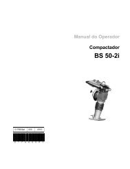
Technical Data <strong>LTC</strong> 4L<br />
2. Technical Data<br />
2.1 <strong>Engine</strong><br />
Item Number: <strong>LTC</strong> 4L - 115V<br />
0009379<br />
<strong>Engine</strong><br />
Make <strong>Lombardini</strong><br />
Model LDW1003<br />
22<br />
<strong>LTC</strong> 4L - 230V<br />
0009485<br />
Type 3-cylinder, 4-cycle, liquid-cooled diesel<br />
Maximum power rating kW (Hp) 8.5 (11.4)<br />
Operating power rating kW (Hp) 7.6 (10.2)<br />
Operating speed<br />
(no-load)<br />
rpm 1500<br />
Alternator V / A / W 12 / 45 / 540<br />
Battery V/Ah/CCA 12 / 450<br />
Air cleaner type dry-type element<br />
Fuel type No. 2 diesel<br />
Fuel tank capacity l (gal.) 114 (30)<br />
Fuel consumption l (gal.) / hr. 1.71 (0.45)<br />
Running time hours 67.7<br />
Coolant capacity l (qts.) 4.7 (5.0)<br />
Oil capacity l (qts.) 2.4 (2.5)<br />
Oil weight SAE 15W40 CD or higher
<strong>LTC</strong> 4L Technical Data<br />
Item Number: <strong>LTC</strong> 4L - 50 Hz<br />
0009377<br />
<strong>Engine</strong><br />
Make <strong>Lombardini</strong><br />
Model LDW1003<br />
Type<br />
3-cylinder, 4-cycle, liquidcooled<br />
diesel<br />
Maximum power rating kW (Hp) 8.5 (11.4)<br />
Operating power rating kW (Hp) 7.6 (10.2)<br />
Operating speed<br />
(no-load)<br />
rpm 1550<br />
Alternator V / A / W 12 / 45 / 540<br />
Battery V/Ah/CCA 12 / 450<br />
Air cleaner type dry-type element<br />
Fuel type No. 2 diesel<br />
Fuel tank capacity l (gal.) 114 (30)<br />
Fuel consumption l (gal.) / hr. 1.70 (0.45)<br />
Running time hours 66.7<br />
Coolant capacity l (qts.) 4.7 (5.0)<br />
Oil capacity l (qts.) 2.4 (2.5)<br />
Oil weight SAE 15W40 CD or higher<br />
23
Technical Data <strong>LTC</strong> 4L<br />
2.2 Generator<br />
Item Number: <strong>LTC</strong> 4L -<br />
115V<br />
0009379<br />
Rev. 104<br />
and higher<br />
Generator<br />
24<br />
<strong>LTC</strong> 4L -<br />
115V<br />
0009379<br />
Rev. 103<br />
and lower<br />
Frequency Hz 50 ± 2<br />
<strong>LTC</strong> 4L -<br />
230V<br />
0009485<br />
Rev. 104<br />
and higher<br />
<strong>LTC</strong> 4L -<br />
230V<br />
0009485<br />
Rev. 103<br />
and lower<br />
Continuous output kW 6.0 5.0 6.0 5.0<br />
Output volts 115 230<br />
Amps A 43.5 21.7<br />
Excitation type Capacitor / Brushless<br />
Power factor 1.0<br />
Voltage regulation -<br />
no load to full load<br />
% ± 5.0<br />
Speed rpm 1500<br />
Item Number: <strong>LTC</strong> 4L - 50 Hz<br />
0009377<br />
Generator<br />
Frequency Hz 50 ± 2<br />
Continuous output kW 5.0<br />
Output volts/phase 230, 1Ø<br />
Amps A 21.7<br />
Excitation type Capacitor / Brushless<br />
Power factor 1.0<br />
Voltage regulation -<br />
no load to full load<br />
% ± 5.0<br />
Speed (no-load) rpm 1550
<strong>LTC</strong> 4L Technical Data<br />
2.3 Machine<br />
Item Number: <strong>LTC</strong> 4L - 115V<br />
0009379<br />
Machine<br />
Height - mast extended m (ft.) 9 (29)<br />
Lighting system<br />
(1000W)<br />
Max. lighting coverage<br />
@ 0.5 ft. candles<br />
Sound level at 7 m<br />
(23 ft.)<br />
Sound pressure level at<br />
operator's location (L pA )<br />
Guaranteed sound<br />
power level (L WA )<br />
m 2 (ft 2 )<br />
acres<br />
dB(A)<br />
dB(A)<br />
dB(A)<br />
Item Number: <strong>LTC</strong> 4L<br />
0009377<br />
Operating weight (GVWR)<br />
Travel Dimensions<br />
(l x w x h)<br />
Machine<br />
kg<br />
(lbs.)<br />
25<br />
4 metal halide light<br />
30,400 (2824)<br />
7<br />
818<br />
(1804)<br />
67<br />
91<br />
97<br />
cm (in.) 441 x 163 x 160<br />
(173 x 64 x 63)<br />
Trailer length cm (in.) 335 (132)<br />
Height - mast extended m (ft.) 9 (30)<br />
Lighting system (1000W) 4<br />
Ballast Coil and core<br />
Max. lighting coverage<br />
@ 0.5 ft. candles<br />
m 2 (acres)<br />
30,400 (7)<br />
Sound level at 7 m (23 ft.) dB(A) 71<br />
Tires size ST175 / 80D13<br />
<strong>LTC</strong> 4L - 230V<br />
0009485
Technical Data <strong>LTC</strong> 4L<br />
26
<strong>LTC</strong> 4L Operation<br />
3. Operation<br />
3.1 Information Regarding Operation<br />
3.2 Locating Trailer<br />
The information regarding the operation of the machine included in this<br />
manual is condensed. Refer to the Operator’s Manual for complete<br />
operating instructions. Always read, understand, and follow the<br />
procedures in the Operator’s Manual when operating the machine.<br />
See Graphic: wc_gr0001420<br />
3.2.1 For maximum light coverage locate the Light Tower at ground level or<br />
in a spot higher than the area being lighted.<br />
3.2.2 Position the trailer on a firm, flat surface clear of overhead wires and<br />
obstructions. Be sure that there is enough area for outrigger<br />
extensions to be fully extended.<br />
3.2.3 Connect the ground stud (l) located on the trailer frame, to a good<br />
earthen ground. Consult local codes for proper grounding techniques.<br />
3.2.1<br />
WARNING<br />
The tower extends up to 9 m (30 ft.). Make sure the area above the<br />
trailer is open and clear of overhead wires and obstructions.<br />
27
Operation <strong>LTC</strong> 4L<br />
3.3 Leveling Trailer<br />
See Graphic: wc_gr001420, wc_gr001423<br />
WARNING<br />
The trailer must be leveled and the outriggers extended before raising<br />
the tower. The outriggers must remain extended while the tower is up.<br />
Failure to level the trailer or extend the outriggers will severely reduce<br />
the stability of the unit and could allow the tower to tip and fall.<br />
3.3.1 Pull the locking pin on the tongue jack (a) and rotate the tongue jack<br />
90° as shown. Make sure the tongue jack snaps into position.<br />
Block or chock the trailer wheels (b). Crank the tongue jack down to<br />
raise the trailer tongue off the vehicle.<br />
3.3.2 Pull the outrigger lock pin (c) to release the outrigger. Pull both<br />
outrigger extensions (d) out until you feel outrigger lock pin lock back<br />
into place. Rotate jacks (e) down until they snap into position.<br />
3.3.3 Rotate rear jack (f) down, as shown, making sure it snaps into place.<br />
3.3.4 Extend the jack(s) on the highest side(s) of the trailer until they rest<br />
firmly on the ground. Extend the remaining jacks until the trailer is<br />
level.<br />
3.4 Adjusting Lights<br />
See Graphic: wc_gr001423<br />
Each light fixture can be aimed up, down, left or right. Position each<br />
fixture by loosening toolless light adjusters (g) and aiming the light up<br />
or down. DO NOT loosen the inside nut (x). Loosening this nut could<br />
cause damage to the light fixture. Loosen the nut (h) to turn light<br />
fixtures left or right. Tighten adjusters and nuts after positioning the<br />
lights.<br />
Always return the light fixtures to aim at the ground when mast is in the<br />
cradle for towing.<br />
28
<strong>LTC</strong> 4L Operation<br />
3.5 Preparing Trailer for Towing or Lifting<br />
See Graphic: wc_gr001423, wc_gr002166<br />
3.5.1 Check that the mast cradle lock pin (j) is in place and secured with the<br />
safety pin.<br />
3.5.2 Ensure that the tower is completely nested inside the transport cradle<br />
and the pin (t) is secure.<br />
3.5.3 Make sure the doors are properly latched.<br />
3.5.4 Return the outriggers to their travel position. Check that the outrigger<br />
bars and jacks are locked in place.<br />
3.5.5 Crank the rear jack (f) all the way in and rotate it 90°.<br />
The the Light Tower is now ready to lift. For towing, continue.<br />
3.5.6 Use the tongue jack (a) to raise the trailer tongue up and then lower it<br />
over hitch on towing vehicle. Lock the hitch to coupling and attach the<br />
safety chains. Swivel the tongue jack 90° and lock it in place.<br />
3.5.7 Connect the trailer wiring to the towing vehicle. Check the brake, turn,<br />
and tail lights for proper operation.<br />
3.5.8 Position the light fixtures down (k). For rough, off-road transportation<br />
remove bulbs from fixtures to avoid damage.<br />
3.5.9 Check the tire inflation.<br />
3.5.10 Attach a red flag to the end of mast before towing.<br />
NOTICE: Maximum recommended speed for highway towing is 72<br />
km/hour (45 MPH). Recommended off-road towing speed is not to<br />
exceed 16 km/hour (10 MPH) or less depending on terrain.<br />
29
Operation <strong>LTC</strong> 4L<br />
3.6 Raising Tower (Manual Winch System)<br />
See Graphic: wc_gr002166<br />
WARNING<br />
WARNING<br />
WARNING<br />
WARNING<br />
NEVER raise the mast or operate the Light Tower in high winds.<br />
NEVER raise the mast while the engine is running.<br />
HIGH VOLTAGE! DO NOT use the Light Tower if insulation on<br />
electrical cord is cut or worn through. <strong>Repair</strong> or replace the cord before<br />
using. Bare wires in contact with the metal frame of the trailer or tower<br />
can cause electrocution.<br />
DO NOT position the Light Tower under electrical power lines.<br />
NEVER allow anyone to stand near the rear of the unit while raising the<br />
mast.<br />
The Light Tower includes two separate winches. One for lifting the<br />
mast to the vertical position, the other for raising the tower. Each winch<br />
is an automatic brake-type winch that automatically brakes when the<br />
handle is released. The handle must be rotated to wind in cable as well<br />
as unwind cable.<br />
NEVER touch the winch pawl! Releasing the pawl may cause the<br />
mast or tower to fall.<br />
3.6.1 Check winch cables (n) for wear or damage, and make sure they are<br />
resting properly in pulleys. Do not use the Light Tower if either winch<br />
cable is damaged.<br />
3.6.2 Remove the cradle locking pin (j) from the cradle.<br />
3.6.3 Check the operation of the tongue-mounted winch (o) by rotating the<br />
winch handle 1/4-turn clockwise (“cable in” direction). The winch pawl<br />
must engage winch gear teeth. When operating properly, the winch<br />
pawl will make a “clicking” sound when the winch handle is rotated<br />
clockwise. Do not attempt to raise the mast if the winch is damaged or<br />
not operating properly.<br />
3.6.4 Continue to rotate the winch handle and raise the mast to the vertical<br />
position until the vertical mast locking pin (p) locks the mast in place.<br />
Be certain the vertical mast locking pin is fully engaged in the locking<br />
position before raising the tower.<br />
30
<strong>LTC</strong> 4L Operation<br />
WARNING<br />
NEVER pull the vertical mast locking pin (p) while the tower is<br />
raised! Releasing the vertical mast locking pin while the tower is<br />
raised may cause the tower to fall or the machine to tip over.<br />
3.6.5 After the mast is in the vertical position, check the operation of the<br />
mast-mounted winch (q) by rotating the winch handle 1/4-turn<br />
clockwise (“cable in” direction). The winch pawl must engage winch<br />
gear teeth. When operating properly, it will make a “clicking” sound<br />
when the winch handle is rotated clockwise. Do not attempt to raise the<br />
mast if the winch is damaged or not operating properly. Continue<br />
rotating the winch handle until mast is at the desired height. Do not<br />
over crank the winch when the tower is fully extended.<br />
NOTICE: Do not extend the tower beyond the red marking on the<br />
mast!<br />
3.6.6 Once the tower is at the desired height, rotate the mast to the desired<br />
direction. To rotate, loosen rotation locking knob (s). Then using the<br />
handle (u), rotate the mast until the lights face the desired direction,<br />
and then retighten the rotation locking knob.<br />
s<br />
o<br />
u<br />
n<br />
q<br />
31<br />
n<br />
p<br />
j<br />
t<br />
wc_gr002166
Operation <strong>LTC</strong> 4L<br />
3.7 Lowering Tower (Manual Winch System)<br />
See Graphic: wc_gr002166<br />
WARNING<br />
WARNING<br />
WARNING<br />
Be sure to read and understand the operating instructions before<br />
lowering the tower!<br />
If for any reason a part of the mast hangs up or a winch cable develops<br />
slack before mast is fully lowered, stop immediately! Continuing to<br />
turn the winch handle will increase the slack in the cable. Too much<br />
slack could cause the mast to collapse should it suddenly free up. If the<br />
mast hangs up, level the trailer. Slightly shake or twist the tower<br />
assembly to free the bind. Contact an authorized WACKER service<br />
representative immediately.<br />
NEVER lower the mast while the unit is operating.<br />
NEVER allow anyone to stand near the rear of the unit while lowering<br />
the mast.<br />
3.7.1 Turn the lights off. Shut down the engine.<br />
NOTICE: Shutting down the engine before turning off the lights could<br />
damage floodlight ballasts or generator capacitor(s).<br />
NOTICE: Observe power cord while lowering the tower. Make sure the<br />
coiled cord is not damaged during the lowering process.<br />
3.7.2 Lower the tower by turning the handle on the mast-mounted winch (q)<br />
counterclockwise (“cable out” direction).<br />
WARNING<br />
NEVER touch the winch pawl! Releasing the winch pawl may cause<br />
the mast or tower to fall.<br />
3.7.3 Loosen the rotation locking knob (s) and using the handle (u), rotate<br />
the mast so the lights face the rear of the trailer and the mast-mounted<br />
winch is facing toward the trailer tongue.<br />
32
<strong>LTC</strong> 4L Operation<br />
s<br />
o<br />
3.7.4 Pull and hold the mast locking pin (p). Rotate the handle on the tonguemounted<br />
winch (o) counterclockwise (“cable out” direction) until the<br />
mast spring begins to pivot the mast down. Release the mast locking<br />
pin and continue to rotate the handle until the mast is resting in the<br />
transport cradle. Be sure that the secondary locking pin (t) penetrates<br />
all sections of the mast.<br />
WARNING<br />
NEVER pull the vertical mast locking pin (e) while the tower is<br />
raised! Releasing the locking pin while the tower is raised may cause<br />
the tower to fall or the machine to tip over.<br />
3.7.5 After the mast is down, secure it in the cradle by inserting the cradle<br />
lock pin (j). Insert the clip through the pin to secure it in place.<br />
3.7.6 Position the light fixtures to aim at the ground.<br />
u<br />
NOTICE: Allow the floodlights to cool 10–15 minutes before moving<br />
trailer. Moving the trailer while the lights are still hot could cause the<br />
bulbs to break.<br />
n<br />
q<br />
33<br />
n<br />
p<br />
j<br />
t<br />
wc_gr002166
Operation <strong>LTC</strong> 4L<br />
3.8 Control Panels—Item 0009377<br />
Floodlight Control Panel <strong>Engine</strong> Control Panel<br />
Ref. Description Ref. Description<br />
a 50 Amp circuit breaker k High Coolant Temperature Shutdown<br />
b 15 Amp lights circuit breaker l Alternator Indicator<br />
c 20 Amp GFI circuit breaker m Auxiliary lights (not used)<br />
d 250 V, 16 Amp Receptacle n Glow Plug Indicator<br />
e Hour Meter o Air Filter Restriction Indicator<br />
f Low Fuel Indicator (not used) p Auxiliary lights (not used)<br />
g Safety Shutdown Indicator q Key Access Door<br />
h Low Oil Pressure Shutdown<br />
34
<strong>LTC</strong> 4L Operation<br />
3.9 Control Panels—Items 0009379 and 0009485<br />
Floodlight Control Panel <strong>Engine</strong> Control Panel<br />
0009485 0009379<br />
EMERGENCY<br />
STOP<br />
t<br />
d<br />
EMERGENCY<br />
STOP<br />
Note: On machine revisions 102 and 103, the generator neutral wire<br />
is not connected to the frame ground or Potential Earth (PE). Be<br />
informed that this machine is wired with an IT Network. Before<br />
connecting this machine to a distribution system, you must consult with<br />
a local electrician for wiring codes.<br />
Ref. Description Ref. Description<br />
t<br />
wc_gr003766<br />
a 50 Amp circuit breaker k High Coolant Temperature Shutdown<br />
b 15 Amp lights circuit breaker l Alternator Indicator<br />
c 20 Amp GFI circuit breaker m Auxiliary lights (not used)<br />
d Receptacle n Glow Plug Indicator<br />
e Hour Meter o Air Filter Restriction Indicator<br />
f Low Fuel Indicator (not used) p Auxiliary lights (not used)<br />
g Safety Shutdown Indicator q Key Access Door<br />
d<br />
h Low Oil Pressure Shutdown t Emergency stop switch<br />
35
Operation <strong>LTC</strong> 4L<br />
3.10 Starting<br />
See Graphic: wc_gr001068, wc_gr001426, wc_gr002758<br />
3.10.1 Check the engine oil, fuel and coolant levels.<br />
Note: If the fuel tank was drained or run dry it may be necessary to<br />
bleed the fuel lines. Refer to the <strong>Engine</strong> Operator’s Manual.<br />
3.10.2 Check the condition of the electrical cable on the mast. Do not start the<br />
generator if the insulation on the cable is cut or worn through.<br />
3.10.3 Check that the circuit breakers (a, b, c) are in their OFF position.<br />
NOTICE: Starting the engine under load will damage the machine.<br />
3.10.4 On machines equipped with the <strong>Lombardini</strong> engine, turn the key (q)<br />
one click to the right. The glow plug indicator (n) will illuminate until the<br />
engine is properly preheated. This is an automatic timer based on the<br />
engine temperature. Crank the engine immediately after the glow plug<br />
light goes off.<br />
3.10.5 Turn the key (q) to START and hold until the engine starts. Release<br />
the key after engine starts.<br />
NOTICE: Do not crank the engine longer than 10 seconds. This could<br />
cause starter motor to overheat. Return switch to OFF and wait 15-30<br />
seconds for the starter motor to cool down before attempting to<br />
preheat and restart.<br />
Note: If the oil pressure is not obtained within 30 seconds after the key<br />
is turned to RUN, the automatic shutdown system will shut off the fuel<br />
supply. You must return the key to the OFF position to restart the 30<br />
second timer before attempting to restart the engine.<br />
3.10.6 Allow the engine to warm up before operating the floodlights.<br />
3.11 Automatic Shutdown<br />
This unit is equipped with a low oil, high temperature auto-shutdown<br />
system. This system will automatically shut off the fuel supply to the<br />
engine if the oil pressure drops too low or the engine exceeds normal<br />
operating temperatures. Return the key switch to “OFF” to reset the<br />
unit after an engine shutdown.<br />
36
<strong>LTC</strong> 4L Operation<br />
3.12 Operating Lights<br />
See Graphic: wc_gr001068, wc_gr001426, wc_gr002758<br />
3.13 Stopping<br />
Turn on the circuit breaker (a) first, then turn each circuit breaker (b) to<br />
“ON”, one at a time.<br />
Metal halide floodlights require a warm-up time of 5–15 minutes before<br />
they reach full output. If the floodlights are shut down, a 10-minute<br />
cool-down period is required before turning them back on.<br />
High pressure sodium floodlights require 1–2 minutes to start and 2–5<br />
minutes of cooldown time to restart.<br />
See Graphic: wc_gr001068, wc_gr001426, wc_gr002758<br />
3.13.1 Turn the circuit breakers (a, b, c) off and remove any other loads from<br />
the generator.<br />
NOTICE: Never shut down the engine without turning off the lights.<br />
Damage to the generator will occur.<br />
3.13.2 Turn the key (q) to OFF.<br />
3.14 Receptacles—50 Hz<br />
See Graphic: wc_gr002933 and wc_gr003766<br />
The control panel is equipped with a convenience receptacle for<br />
running accessories and tools from the generator. Power to this<br />
receptacle is available any time the engine is running and the circuit<br />
breaker is “ON”.<br />
NOTICE: Do not draw more than 2000 Watts from the receptacle with<br />
all of the lights on.<br />
A 20A circuit breaker (c) protects the 250V (0009485), 115V<br />
(0009379) receptacle (d).<br />
37
Maintenance <strong>LTC</strong> <strong>Repair</strong><br />
4. Maintenance<br />
4.1 Periodic Maintenance Schedule<br />
38<br />
Before<br />
each<br />
use<br />
Check for fluid leaks. <br />
Check engine oil. <br />
Check fuel level. <br />
Replace air filter if indicator light is on.** <br />
Every<br />
125<br />
hours<br />
Change engine oil.* <br />
Check level of battery electrolyte. <br />
Every<br />
250<br />
hours<br />
Check condition and tension on fan belt. <br />
Check condition of radiator hoses. <br />
Replace oil filter.* <br />
Replace fuel filter. <br />
Flush radiator. <br />
Replace fan belt. <br />
Check valve clearance. <br />
Every<br />
500<br />
hours<br />
Every<br />
1000 hours<br />
or two years<br />
Remove sediment in fuel tank. <br />
Change radiator coolant. <br />
Replace battery. <br />
Replace radiator hoses and clamps. <br />
Replace fuel pipes and clamps. <br />
* Change engine oil and filter after first 50 hours of operation.<br />
** Replace air filter after air filter restriction switch indication or one year. <strong>Lombardini</strong> does not<br />
recommend the removal of air filter elements for purposes of inspection.
<strong>LTC</strong> <strong>Repair</strong> Maintenance<br />
4.2 Daily Inspection<br />
4.2.1 Check for fluid leaks. Check fluid levels.<br />
4.2.2 Inspect condition of electrical cords. Do not use light tower if insulation<br />
is cut or worn through.<br />
4.2.3 Check that winch cables are in good condition. Do not use a cable that<br />
is kinked or starting to unravel.<br />
4.2.4 Check that the vertical mast locking pin and its spring are secured,<br />
aligned, and operating properly.<br />
39
Maintenance <strong>LTC</strong> <strong>Repair</strong><br />
4.3 Installing / Removing Light Fixtures<br />
b<br />
See Graphic: wc_gr003907<br />
WARNING<br />
WARNING<br />
ALWAYS turn off the light circuit breakers and shut down the engine<br />
before disconnecting the light fixtures or changing the light bulbs.<br />
The bulbs become extremely hot in use! Allow the bulb and the<br />
fixture to cool 10–15 minutes before handling them.<br />
4.3.1 Remove the fixtures by disconnecting the electrical wiring at the<br />
junction box (a). NOTICE: Only a trained technician should be allowed<br />
to install and remove the fixture wiring.<br />
4.3.2 Remove the nuts (b) from the fixture mounting brackets and remove<br />
both the fixture and the bracket off the stud.<br />
4.3.3 Adjusting clamps (c) may be moved from side to side as desired by<br />
unscrewing them and swapping positions with the locknut on the<br />
oppositie side of the fixture.<br />
a<br />
c<br />
50Hz 60Hz<br />
40<br />
b<br />
a<br />
c<br />
wc_gr003907
<strong>LTC</strong> <strong>Repair</strong> Maintenance<br />
4.4 Precautions When Replacing / Removing Bulbs<br />
WARNING<br />
WARNING<br />
WARNING<br />
The Light Tower uses four 1000W bulbs. When replacing or removing<br />
the bulbs, avoid leaving any grease or oil residue on the glass surface.<br />
This can create hot spots, reducing the service life of the bulb or<br />
causing the outer jacket to burst.<br />
ALWAYS turn off the light circuit breakers and shut down the engine<br />
before disconnecting the light fixtures or changing the light bulbs.<br />
Bulbs become extremely hot in use! Allow the bulb and fixture to<br />
cool 10–15 minutes before handling.<br />
NEVER operate the lights without the protective lens cover in<br />
place or with a lens cover that is cracked or damaged! The lamps<br />
used in the floodlights produce high temperatures and operate under<br />
pressure. They are subject to failures where the outer jacket bursts<br />
and shatters, resulting in a discharge of extremely hot glass particles.<br />
These particles pose a risk of personal injury, property damage, burns<br />
and fire.<br />
Ultraviolet radiation from the lamp can cause serious skin and eye<br />
irritation. Use the lamp only with provided undamaged lens cover and<br />
fixture.<br />
41
Maintenance <strong>LTC</strong> <strong>Repair</strong><br />
4.5 Replacing Bulbs<br />
See Graphic: wc_gr002464<br />
Removal:<br />
4.5.1 Shut down the engine and allow the bulb to cool.<br />
4.5.2 Remove the screws (a) securing the flange rings (b) and remove the<br />
flange rings.<br />
4.5.3 Remove the lens (c) with the gasket (d) attached.<br />
4.5.4 Remove the hardware securing one side of the bulb stabilizer (e).<br />
Once removed, swing the bulb stabilizer to the side and unscrew the<br />
bulb (f).<br />
Installation:<br />
4.5.5 Insert the bulb and secure it with the bulb stabilizer (e).<br />
4.5.6 Install the gasket (d) around the lens (c) and secure the lens to the<br />
reflector with flange ring (b) and screws (a).<br />
c<br />
d<br />
a<br />
b<br />
42<br />
f<br />
e<br />
wc_gr002464
<strong>LTC</strong> <strong>Repair</strong> Maintenance<br />
4.6 Air Cleaner<br />
See Graphic: wc_gr000540<br />
Replace the air filter cartridge when the indicator (o) mounted on the<br />
control panel appears.<br />
4.6.1 Open air cleaner and remove element.<br />
4.6.2 To clean the filter, lightly tap on a hard surface to eliminate all excess<br />
dirt. Do not blow the paper filter element with compressed air to clean.<br />
Clean the filter cover and support carefully.<br />
4.6.3 Reassemble the filtering element and air cleaner.<br />
4.7 <strong>Engine</strong> Oil<br />
See Graphic: wc_gr000541<br />
Drain the oil while the engine is still warm.<br />
Note: In the interests of environmental protection, place a plastic sheet<br />
and a container under the machine to collect any liquid which drains<br />
off. Dispose of this liquid in accordance with environmental protection<br />
legislation.<br />
4.7.1 Remove the oil drain plug.<br />
4.7.2 Allow the oil to drain.<br />
4.7.3 Install the oil drain plug.<br />
4.7.4 Fill the engine crankcase through the oil filler opening, to the upper<br />
mark on the dipstick. See Technical Data for oil quantity and type.<br />
4.7.5 Install the oil filter cap.<br />
43<br />
wc_gr000540<br />
wc_gr000541
Maintenance <strong>LTC</strong> <strong>Repair</strong><br />
44<br />
4.8 <strong>Lombardini</strong> <strong>Engine</strong> Wiring<br />
13<br />
2<br />
3<br />
1<br />
8<br />
4<br />
R<br />
x<br />
x<br />
x<br />
x<br />
7<br />
16<br />
17<br />
11<br />
9<br />
10<br />
12<br />
14<br />
5<br />
B+<br />
Pr<br />
L<br />
L<br />
G<br />
G<br />
B<br />
Or<br />
Or<br />
B<br />
B<br />
D+<br />
W<br />
12V/45A<br />
wc_gr003225<br />
15<br />
14<br />
13<br />
12<br />
11<br />
10<br />
9<br />
8<br />
7<br />
6<br />
5<br />
4<br />
3<br />
1<br />
2<br />
8<br />
9<br />
10<br />
11<br />
12<br />
13<br />
14<br />
1<br />
2<br />
3<br />
4<br />
5<br />
7<br />
6<br />
3<br />
1 2<br />
P/B<br />
L<br />
L<br />
B<br />
6
<strong>LTC</strong> <strong>Repair</strong> Maintenance<br />
4.9 <strong>Engine</strong> Wiring Components<br />
Ref. Description Ref. Description Ref. Description<br />
1 Emergency stop switch<br />
(50 Hz only)<br />
7 Air filter restriction<br />
indicator<br />
(normal open type)<br />
45<br />
13 Harness connector<br />
(alternator)<br />
2 Glow plugs 8 Terminal strip 14 Diode<br />
3 Starter motor 9 Low oil pressure switch 15 Resistors<br />
(2x220 Ohm, 0.6 W)<br />
4 Battery 10 High coolant<br />
temperature switch<br />
(normal open type)<br />
5 Alternator connector 11 Harness connector<br />
(control panel)<br />
16 Control panel<br />
17 Control panel connector<br />
6 Fuel pump 12 Alternator x Not used
Maintenance <strong>LTC</strong> <strong>Repair</strong><br />
4.10 <strong>Engine</strong> Control Panel Internal Wiring—<strong>Lombardini</strong><br />
EV<br />
3 R/W<br />
(Max 0,8A)<br />
S1<br />
ACC<br />
6 V<br />
(Max 10A)<br />
"A"<br />
(12V)<br />
5 B<br />
(Max 12A)<br />
14<br />
S5<br />
L<br />
Y/G<br />
70A<br />
"B"<br />
(Max 50A) B<br />
c<br />
a<br />
15<br />
30<br />
50<br />
7 R<br />
f<br />
b<br />
Ref. Description Ref. Description<br />
a Key switch d <strong>Engine</strong> protection<br />
b 15A fuse e Preheating<br />
c 80A fuse f Relay<br />
4<br />
Or Br<br />
d<br />
S3<br />
13<br />
e<br />
Wire Colors<br />
B Black R Red Y Yellow Or Orange<br />
G Green T Tan Br Brown Pr Purple<br />
L Blue V Violet Cl Clear Sh Shield<br />
S2<br />
P Pink W White Gr Gray LL Light blue<br />
46<br />
S4<br />
G<br />
Y<br />
9 8 10 1 11 12 2<br />
W Gr<br />
G Y L P W/L<br />
R R R R Y R R<br />
8<br />
9<br />
10<br />
11<br />
12<br />
13<br />
14<br />
1<br />
2<br />
3<br />
4<br />
5<br />
6<br />
7<br />
"A"<br />
"B"<br />
LL<br />
B<br />
wc_gr003226
<strong>LTC</strong> <strong>Repair</strong> Maintenance<br />
4.11 <strong>Engine</strong> Control Panel Components—<strong>Lombardini</strong><br />
a 1<br />
Ref. Description Ref. Description<br />
a1 <strong>Engine</strong> control panel, front view f System fuse—80A<br />
a2 <strong>Engine</strong> control panel, rear view g Key access door<br />
b Solid-state glow plug controller and<br />
indicating lamps<br />
47<br />
h Auxiliary connections<br />
c Shutdown relay location i Light switch panel connection<br />
d Glow plug relay j 15A fuse<br />
e Key switch - --<br />
g<br />
e<br />
j<br />
50<br />
30<br />
a 2<br />
86<br />
87<br />
30<br />
85<br />
wc_gr003227<br />
b<br />
c<br />
d<br />
f
Maintenance <strong>LTC</strong> <strong>Repair</strong><br />
4.12 Wiring Diagram: 50Hz 230V 0009377<br />
L L<br />
q r W<br />
h<br />
Or<br />
G/Y<br />
Or<br />
p<br />
48<br />
b<br />
i<br />
wc_gr003769
<strong>LTC</strong> <strong>Repair</strong> Maintenance<br />
4.13 Components: 50Hz 230V 0009377<br />
e<br />
Ref. Description Ref. Description<br />
a Generator j Receptacle, 230V<br />
b Main circuit breaker k Hour meter<br />
c Junction box m Floodlight capacitor, 30µF<br />
d Floodlights n Ballast/transformer<br />
e Terminal strip, long o Battery<br />
f Circuit breaker, 20A p Generator capacitor, 35µF<br />
g Circuit breaker, 15A q Starter solenoid<br />
h <strong>Engine</strong> r Alternator<br />
i Terminal strip, short - ---<br />
Wire Colors<br />
B Black R Red Y Yellow Or Orange<br />
G Green T Tan Br Brown Pr Purple<br />
L Blue V Violet Cl Clear Sh Shield<br />
P Pink W White Gr Gray LL Light blue<br />
49
Maintenance <strong>LTC</strong> <strong>Repair</strong><br />
4.14 Wiring Diagram: 50Hz 115V 0009379<br />
L L<br />
+<br />
–<br />
Or<br />
q o W<br />
h<br />
i<br />
Or<br />
P/B<br />
Or<br />
50<br />
p<br />
wc_gr003767
<strong>LTC</strong> <strong>Repair</strong> Maintenance<br />
4.15 Components: 50Hz 115V 0009379<br />
Ref. Description Ref. Description<br />
a Generator k Hour meter<br />
b Terminal strip, long m Floodlight capacitor, 30µF<br />
c Main circuit breaker n Ballast/transformer<br />
d Floodlights o Alternator<br />
e Receptacle p Terminal strip, short<br />
f Circuit breaker, 20A q Starter solenoid<br />
g Circuit breaker, 15A r Emergency stop switch<br />
h Battery s Fuel solenoid<br />
i <strong>Engine</strong> t Generator capacitor, 35µF<br />
j Junction box - ---<br />
Wire Colors<br />
B Black R Red Y Yellow Or Orange<br />
G Green T Tan Br Brown Pr Purple<br />
L Blue V Violet Cl Clear Sh Shield<br />
P Pink W White Gr Gray LL Light blue<br />
51
Maintenance <strong>LTC</strong> <strong>Repair</strong><br />
4.16 Wiring Diagram: 50 Hz 230V 0009485<br />
L L<br />
+<br />
–<br />
Or<br />
q o W<br />
h<br />
i<br />
Or<br />
P/B<br />
Or<br />
52<br />
p<br />
wc_gr003768
<strong>LTC</strong> <strong>Repair</strong> Maintenance<br />
4.17 Components: 50Hz 230V 0009485<br />
Ref. Description Ref. Description<br />
a Generator k Hour meter<br />
b Terminal strip, long m Floodlight capacitor, 30µF<br />
c Main circuit breaker n Ballast/transformer<br />
d Floodlights o Alternator<br />
e Receptacle p Terminal strip, short<br />
f Circuit breaker, 20A q Starter solenoid<br />
g Circuit breaker, 15A r Emergency stop switch<br />
h Battery s Fuel solenoid<br />
i <strong>Engine</strong> t Generator capacitor, 35µF<br />
j Junction box - ---<br />
Wire Colors<br />
B Black R Red Y Yellow Or Orange<br />
G Green T Tan Br Brown Pr Purple<br />
L Blue V Violet Cl Clear Sh Shield<br />
P Pink W White Gr Gray LL Light blue<br />
53
Maintenance <strong>LTC</strong> <strong>Repair</strong><br />
4.18 Generator Capacitor Excitation Schematic<br />
–<br />
+<br />
–<br />
+<br />
8<br />
8<br />
Rectified<br />
Output<br />
Rectified<br />
Output<br />
5 7<br />
1<br />
Excitation<br />
1<br />
Excitation<br />
Ref. Description Ref. Description<br />
1 Rotor winding 5 Rotor<br />
2 Stator winding 6 Short terminal strip<br />
3 Excitation winding 7 Stator<br />
4 Excitation capacitor 8 Rotor diode<br />
2<br />
2<br />
3<br />
54<br />
120V<br />
120V<br />
4<br />
C1<br />
240V<br />
T1<br />
T2<br />
COMMON<br />
T3<br />
T4<br />
6<br />
wc_gr003535
<strong>LTC</strong> <strong>Repair</strong> Maintenance<br />
4.19 Trailer Wiring<br />
55
<strong>Lombardini</strong> <strong>Engine</strong> <strong>Troubleshooting</strong> <strong>LTC</strong> <strong>Repair</strong><br />
5. <strong>Lombardini</strong> <strong>Engine</strong> <strong>Troubleshooting</strong><br />
5.1 <strong>Troubleshooting</strong> Flowcharts<br />
The troubleshooting flowcharts are designed to take you through the<br />
process of determining the source of a problem with engine starting or<br />
machine operation. Many of the tests involve live voltages and<br />
therefore should only be attempted by qualified personnel. Detailed<br />
procedures for carrying out the tests are included in this manual. All<br />
highlighted text within the flowcharts have matching sections in this<br />
manual.<br />
56
<strong>LTC</strong> <strong>Repair</strong> <strong>Lombardini</strong> <strong>Engine</strong> <strong>Troubleshooting</strong><br />
5.2 <strong>Engine</strong> Does Not Crank—Flowchart 3A<br />
<strong>Engine</strong> Does Not Crank<br />
Check battery voltage.<br />
Consult<br />
<strong>Lombardini</strong><br />
<strong>Engine</strong> <strong>Repair</strong><br />
Manual.<br />
Does<br />
battery measure<br />
11.0–13.0V?<br />
No<br />
Recharge or<br />
replace battery.<br />
Yes<br />
Yes<br />
Reconnect<br />
black wire.<br />
Clean and<br />
tighten connections.<br />
<strong>Repair</strong> wiring<br />
from terminal 30<br />
to battery.<br />
Check for battery voltage<br />
between black wire at starter<br />
solenoid and ground when<br />
key is in START position.<br />
Is battery<br />
voltage measured<br />
between black wire<br />
and ground?<br />
No<br />
<strong>Repair</strong>/replace<br />
black wire.<br />
57<br />
No<br />
No<br />
Is<br />
the black wire<br />
connected?<br />
Yes<br />
Are<br />
connections clean<br />
and tight?<br />
Yes<br />
Check for battery voltage between<br />
terminal 30 of keyswitch and ground.<br />
No<br />
Is battery<br />
voltage measured<br />
between 30 and<br />
ground?<br />
Yes<br />
Check for battery voltage between<br />
terminal 50 and ground when key<br />
is placed in the START position.<br />
Yes<br />
Check connection of black wire at<br />
starter solenoid. Also check wire<br />
connections at back of keyswitch.<br />
See Checking Keyswitch and Wiring.<br />
Is battery<br />
voltage measured<br />
between 50 and<br />
ground?<br />
No<br />
Replace keyswitch.<br />
wc_gr003502
<strong>Lombardini</strong> <strong>Engine</strong> <strong>Troubleshooting</strong> <strong>LTC</strong> <strong>Repair</strong><br />
5.3 Checking Keyswitch and Wiring<br />
See Graphic: wc_gr003509<br />
WARNING<br />
Electric shock hazard. Only qualified personnel should conduct these<br />
tests.<br />
5.3.1 When troubleshooting <strong>Lombardini</strong> engines that do not crank, check<br />
that the B (black) wire (a) is connected to the starter solenoid.<br />
5.3.2 Remove the screws securing the control panel (b) to the mounting<br />
bracket and remove the control panel from the bracket.<br />
5.3.3 Remove the back cover (c) of the control panel box and check that the<br />
the wiring to the keyswitch (d) is clean and tight. Check that the<br />
appropriate wires are connected to the proper terminals of the<br />
keyswitch.<br />
5.3.4 Check for 12V (battery voltage approximately 12) between terminal 30<br />
of keyswitch and ground. If no voltage is measured, repair wiring back<br />
to battery. If voltage is measured, continue.<br />
5.3.5 Place the keyswitch in the START position and check for 12V (battery<br />
voltage approximately 12) between terminal 50 of the keyswitch and<br />
ground. If no voltage is measured, replace the keyswitch. If voltage is<br />
measured, continue.<br />
5.3.6 Place the keyswitch in the START position and check for 12V (battery<br />
voltage approximately 12) between the B (black) wire (a) and ground<br />
at the starter solenoid. If no voltage is measured, repair the wiring<br />
between terminal 50 of the keyswitch and the starter solenoid. If<br />
voltage is measured and the engine still will not crank, there is a<br />
problem with the starter motor. See the <strong>Lombardini</strong> <strong>Engine</strong> <strong>Repair</strong><br />
Manual for further information.<br />
58
<strong>LTC</strong> <strong>Repair</strong> <strong>Lombardini</strong> <strong>Engine</strong> <strong>Troubleshooting</strong><br />
c<br />
d<br />
a<br />
59<br />
V<br />
50<br />
15/54<br />
B<br />
L<br />
30<br />
b<br />
wc_gr003509
<strong>Lombardini</strong> <strong>Engine</strong> <strong>Troubleshooting</strong> <strong>LTC</strong> <strong>Repair</strong><br />
5.4 Replacing Keyswitch<br />
See Graphic: wc_gr003510<br />
Disassembly:<br />
5.4.1 Shut down the engine and disconnect the battery.<br />
5.4.2 Remove the six screws securing the control panel cover to the control<br />
panel.<br />
5.4.3 Make note of the wire connections on the keyswitch and remove the<br />
wires (a) from the keyswitch.<br />
5.4.4 Unscrew the locking ring (b) and remove the keyswitch from the<br />
control panel.<br />
Reassembly:<br />
5.4.5 Insert the replacement keyswitch into the control panel and secure it<br />
with the locking ring (b).<br />
5.4.6 Attach the wires (a) to the appropriate terminals of the keyswitch.<br />
5.4.7 Secure the control panel cover to the control panel with the six screws.<br />
b<br />
60<br />
a<br />
V<br />
50<br />
15/54<br />
B<br />
L<br />
30<br />
wc_gr003510
<strong>LTC</strong> <strong>Repair</strong> <strong>Lombardini</strong> <strong>Engine</strong> <strong>Troubleshooting</strong><br />
5.5 <strong>Engine</strong> Cranks But Does Not Start—Flowchart 4A<br />
Replace<br />
battery.<br />
Gravity feed fuel<br />
through fuel intake<br />
hose.<br />
<strong>Engine</strong> Cranks But Does Not Start<br />
Make sure that the machine<br />
has fresh fuel and that the<br />
fuel filter and fuel hoses are<br />
in good condition.<br />
Check battery condition.<br />
No<br />
Does<br />
battery provide<br />
correct voltage and<br />
CCA?<br />
Yes<br />
Yes<br />
Check fuel solenoid wiring.<br />
Is<br />
fuel pump solenoid<br />
operating?<br />
No<br />
Consult<br />
<strong>Lombardini</strong><br />
<strong>Engine</strong> <strong>Repair</strong><br />
Manual.<br />
Replace glow plugs.<br />
61<br />
No<br />
Yes<br />
Yes<br />
Check if fuel flows from inlet<br />
hose when engine is cranking.<br />
See Checking Fuel System<br />
Does<br />
fuel flow from inlet<br />
hose?<br />
Yes<br />
Check glow plugs.<br />
See Checking Glow Plugs.<br />
Do<br />
glow plugs operate<br />
correctly?<br />
No<br />
Check glow plug relay.<br />
See Checking Glow Plug Relay.<br />
Does<br />
glow plug relay operate<br />
correctly?<br />
No<br />
Replace glow<br />
plug relay.<br />
wc_gr003503
<strong>Lombardini</strong> <strong>Engine</strong> <strong>Troubleshooting</strong> <strong>LTC</strong> <strong>Repair</strong><br />
5.6 Checking Fuel System<br />
See Graphic: wc_gr002470<br />
WARNING<br />
Electric shock hazard. Only qualified personnel should conduct these<br />
tests.<br />
When troubleshooting <strong>Lombardini</strong> engines that crank but do not start,<br />
make the following checks.<br />
5.6.1 Check that the battery is in good condition and that all connections are<br />
clean and tight. If the battery voltage falls below 11.5V, replace the<br />
battery.<br />
5.6.2 Fill the fuel tank with fresh fuel and check that the fuel hoses and fuel<br />
filter are clean and in good condition.<br />
5.6.3 Disconnect the fuel intake hose (a). Have a suitable container ready to<br />
catch the fuel. Place the keyswitch in the START position and check if<br />
the fuel flows from the hose.<br />
If fuel flows from the hose, reconnect the hose.<br />
If fuel does not flow from the hose, continue.<br />
5.6.4 Disconnect the power lead (b) to the fuel solenoid. Place the keyswitch<br />
in the START position and check for battery voltage between the lead<br />
and ground.<br />
a<br />
If battery voltage is not measured, check the continuity of wiring.<br />
See the <strong>Lombardini</strong> <strong>Engine</strong> <strong>Repair</strong> Manual for further information.<br />
If battery voltage is measured, check the power to the glow plugs.<br />
62<br />
b<br />
wc_gr002470
<strong>LTC</strong> <strong>Repair</strong> <strong>Lombardini</strong> <strong>Engine</strong> <strong>Troubleshooting</strong><br />
5.7 Checking Voltage to Glow Plugs (<strong>Lombardini</strong> 1003 engines)<br />
See Graphic: wc_gr003229<br />
To check the voltage to the glow plugs, carry out the following<br />
procedure:<br />
5.7.1 Disconnect the B (black) wire (a), place the keyswitch in the START<br />
position, and measure the voltage between the black wire and ground.<br />
There should be 12V (battery voltage approximately 12) measured.<br />
If 12V is measured, check the function of the glow plug.<br />
If 12V is not measured, continue.<br />
5.7.2 Disconnect the B (black) wire (b) and measure the voltage between it<br />
and ground. There should be 12V (battery voltage approximately 12)<br />
measured.<br />
If 12V is measured, clean the connection points of the wires.<br />
Reconnect the wires and check the function of the glow plug.<br />
If 12V is not measured, check the glow plug relay.<br />
a<br />
b<br />
63<br />
wc_gr003229
<strong>Lombardini</strong> <strong>Engine</strong> <strong>Troubleshooting</strong> <strong>LTC</strong> <strong>Repair</strong><br />
5.8 Checking Glow Plug Relay<br />
See Graphic: wc_gr002475<br />
5.8.1 Remove the screws securing the engine control panel. Leave all wiring<br />
connected to the control panel.<br />
5.8.2 Rotate the control panel to gain access to the rear of the control panel.<br />
Remove the enclosure cover to access the glow plug relay.<br />
5.8.3 Place the keyswitch in the START position. A working relay will “click”<br />
when the keyswitch is in the START position.<br />
Check the continuity across the blue (L) and black (B) wires when the<br />
keyswitch is in the START position. If there is no continuity, the relay<br />
is faulty; replace it.<br />
5.9 Replacing Glow Plug Relay<br />
See Graphic: wc_gr002475<br />
5.9.1 Make note of the wire positions and disconnect all wires from the glow<br />
plug relay.<br />
5.9.2 Bend back the tabs (a) securing the glow plug relay (b) and pull the<br />
glow plug relay from the enclosure.<br />
64
<strong>LTC</strong> <strong>Repair</strong> <strong>Lombardini</strong> <strong>Engine</strong> <strong>Troubleshooting</strong><br />
5.10 Checking Glow Plugs<br />
See Graphic: wc_gr002033<br />
5.10.1 Remove the glow plug from the engine.<br />
WARNING<br />
Burn hazard. Glow plugs can reach temperatures up to 1200°F<br />
(649°C). Do not touch the element of the glow plug. Be extremely<br />
careful when testing the glow plug.<br />
5.10.2 Using 10-gauge wire, apply 12VDC to the glow plug—positive on the<br />
upper portion and ground the base. If the glow plug does not heat<br />
(glow) within five seconds, replace the glow plug.<br />
Note: If any one of the glow plugs needs replacing, replace all of them.<br />
65
<strong>Lombardini</strong> <strong>Engine</strong> <strong>Troubleshooting</strong> <strong>LTC</strong> <strong>Repair</strong><br />
5.11 <strong>Engine</strong> Shuts Down—Flowchart 5A<br />
<strong>Engine</strong> Shuts Down<br />
Check engine oil level.<br />
Is machine oil<br />
level correct?<br />
Yes<br />
Check engine<br />
coolant level.<br />
Is<br />
engine coolant<br />
level correct?<br />
No<br />
Fill engine with<br />
correct amount and<br />
type of coolant.<br />
No<br />
Yes<br />
Fill machine<br />
with oil.<br />
Check wiring of oil pressure<br />
switch.<br />
Check wiring of coolant<br />
temperature switch.<br />
See Checking Oil Pressure and<br />
Coolant Temperature Switches.<br />
Is<br />
oil pressure<br />
switch connected<br />
correctly?<br />
66<br />
Yes<br />
Is<br />
coolant temperature<br />
switch connected<br />
correctly?<br />
Yes<br />
Refer to the<br />
<strong>Lombardini</strong> <strong>Engine</strong> <strong>Repair</strong><br />
Manual.<br />
Call <strong>Wacker</strong> Corporation<br />
Service.<br />
No<br />
No<br />
Connect oil<br />
pressure switch<br />
and/or repair wiring.<br />
Connect coolant<br />
temperature switch<br />
and/or repair wiring.<br />
wc_gr003504
<strong>LTC</strong> <strong>Repair</strong> <strong>Lombardini</strong> <strong>Engine</strong> <strong>Troubleshooting</strong><br />
5.12 Checking Oil Pressure and Coolant Temperature Switches<br />
See Graphic: wc_gr003230<br />
5.12.1 If the engine starts but shuts down after approximately 10 seconds,<br />
check the following.<br />
5.12.2 Check the engine oil level and add oil if necessary. Also check the<br />
coolant temperature. If the coolant temperature is high, allow the<br />
engine to cool. Flush and fill the radiator with the correct coolant.<br />
5.12.3 Check the wiring of the oil pressure switch (a) and the coolant<br />
temperature switch (b) (903 engines) or (c) (1003 engines). If the<br />
wiring of either switch is shorted to ground, the engine will shut down.<br />
Be sure the switches are functioning—check each for continuity. The<br />
oil pressure switch is a normally closed (NC) switch that should have<br />
continuity when the engine is off. If the switch has no continuity when<br />
the engine is off, the switch is faulty; replace it.<br />
The high coolant temperature switch is a normally open (NO) switch.<br />
This switch should have no continuity when the engine is off. If this<br />
switch has continuity when the engine is off, it has shorted and is faulty;<br />
replace it.<br />
c<br />
a<br />
67<br />
b<br />
wc_gr003230
<strong>Lombardini</strong> <strong>Engine</strong> <strong>Troubleshooting</strong> <strong>LTC</strong> <strong>Repair</strong><br />
5.13 General <strong>Engine</strong> <strong>Troubleshooting</strong><br />
Possible Cause Symptom<br />
<strong>Engine</strong> will not crank<br />
<strong>Engine</strong> does not start<br />
<strong>Engine</strong> starts, but stops<br />
68<br />
Poor acceleration<br />
Unsteady rpm<br />
Low fuel level <br />
Fuel supply/return lines<br />
clogged<br />
<br />
Clogged fuel tank vent <br />
Fuel pump faulty <br />
Fuel contaminated with air <br />
Unit injector(s) faulty/worn <br />
Unit injector settings incorrect <br />
Injection pump rack sticking <br />
Oil level too high <br />
Improper oil viscosity <br />
Oil diluted by fuel <br />
Oil pressure relief valve faulty<br />
Oil pick-up tube clogged<br />
Oil pump air contaminated at<br />
pick-up tube<br />
Black smoke<br />
Glow plugs faulty <br />
Glow plug controller faulty<br />
Glow plug relay inoperable<br />
Starter defective<br />
<br />
<br />
<br />
White smoke<br />
Blue smoke<br />
Low oil pressure<br />
<br />
<br />
<br />
Oil level rising<br />
Excessive oil consumption<br />
Wet exhaust<br />
Overheating<br />
<strong>Engine</strong> knocks
<strong>LTC</strong> <strong>Repair</strong> <strong>Lombardini</strong> <strong>Engine</strong> <strong>Troubleshooting</strong><br />
Possible Cause Symptom<br />
Battery voltage too low<br />
Battery/battery cable<br />
connections corroded<br />
Key switch defective<br />
<br />
<br />
<br />
Air filter clogged <br />
Excessive idle/light load<br />
operation<br />
69<br />
<br />
Incomplete engine run-in <br />
<strong>Engine</strong> overloaded <br />
Excessive secondary load <br />
Valve lash insufficient/<br />
excessive<br />
Injection timing out of spec -<br />
advanced<br />
Injection timing out of spec -<br />
retarded<br />
Governor linkage adjustment<br />
incorrect<br />
Governor spring fatigued or<br />
defective<br />
<strong>Engine</strong> will not crank<br />
<strong>Engine</strong> does not start<br />
Idle rpm too low <br />
<br />
<br />
<br />
<br />
<br />
Piston rings worn or stuck <br />
Piston worn or damaged <br />
Cylinders worn or damaged <br />
Valve/valve guides worn <br />
<strong>Engine</strong> starts, but stops<br />
Poor acceleration<br />
Unsteady rpm<br />
Black smoke<br />
White smoke<br />
Blue smoke<br />
Low oil pressure<br />
Oil level rising<br />
Excessive oil consumption<br />
Wet exhaust<br />
Overheating<br />
<strong>Engine</strong> knocks
<strong>Lombardini</strong> <strong>Engine</strong> <strong>Troubleshooting</strong> <strong>LTC</strong> <strong>Repair</strong><br />
Possible Cause Symptom<br />
Valves sticking <br />
Bearings (main/rod) worn <br />
Governor/governor linkage<br />
malfunctioning<br />
Cylinder head gasket<br />
damaged<br />
Thermostat stuck or<br />
malfunctioning<br />
<strong>Engine</strong> seized<br />
Radiator clogged (external or<br />
internal)<br />
Coolant pump faulty<br />
<strong>Engine</strong> will not crank<br />
<br />
<strong>Engine</strong> does not start<br />
<strong>Engine</strong> starts, but stops<br />
<br />
<br />
Turbocharger faulty <br />
70<br />
Poor acceleration<br />
Unsteady rpm<br />
Black smoke<br />
White smoke<br />
Blue smoke<br />
Low oil pressure<br />
Oil level rising<br />
Excessive oil consumption<br />
Wet exhaust<br />
Overheating<br />
<br />
<br />
<br />
<strong>Engine</strong> knocks
<strong>LTC</strong> <strong>Repair</strong> <strong>Lombardini</strong> <strong>Engine</strong> <strong>Troubleshooting</strong><br />
Notes<br />
71
Electrical <strong>Troubleshooting</strong> Procedures <strong>LTC</strong> <strong>Repair</strong><br />
6. Electrical <strong>Troubleshooting</strong> Procedures<br />
6.1 <strong>Troubleshooting</strong> Methodology<br />
If a lighting problem is not an obvious burnt bulb, engine speed, or wire<br />
fault, the cause of the problem will be associated with one of two<br />
things: 1) a malfunctioning generator, or 2) faults in the circuit<br />
supplying voltage to the lights. By starting the troubleshooting<br />
procedures with the smaller terminal strip (the terminal strip where the<br />
wires from the generator are connected) you can determine whether<br />
the problem lies within the generator, or if the problem lies with the<br />
circuit supplying the lights.<br />
For troubleshooting a malfunctioning generator, you will need to rule<br />
out a demagnetized rotor or problems with: the generator’s excitation<br />
capacitor, the stator windings, the rotor diodes, and finally the rotor<br />
windings.<br />
For troubleshooting the lighting circuit, you will need to rule out<br />
problems with: the main circuit breaker, the long terminal strip, the<br />
individual circuit breakers, the ballast transformer, the lighting ballast<br />
capacitors, and the wiring that connects all the components.<br />
Detailed procedures for making the tests are included in the upcoming<br />
sections of this manual.<br />
72
<strong>LTC</strong> <strong>Repair</strong> Electrical <strong>Troubleshooting</strong><br />
6.2 Checking Continuity<br />
Conduct continuity tests when the engine is shut down.<br />
When checking continuity, use the Ohm setting on your multimeter.<br />
Place a lead of the multimeter on one end of the wiring or component<br />
and the other lead on the opposite end. If your meter reads “OL” or<br />
“OPEN”, there is no continuity and the wiring or component must be<br />
repaired or replaced.<br />
Note: Some multimeters also have an audio signal setting for<br />
determining continuity. This setting may also be used.<br />
If your meter reads less than 1.0 Ohm, or the audio signal<br />
sounds, the wiring or component has continuity and should be<br />
OK.<br />
If your meter reads more than 1.0 Ohm, the wiring is faulty and<br />
must be repaired or replaced.<br />
6.3 Checking resistance<br />
6.4 Checking voltage<br />
Conduct resistance checks when the engine is shut down.<br />
Use the Ohm setting on your multimeter.<br />
Conduct resistance checks when the machine is as close to 21°C<br />
(70°F) as possible. Higher temperatures can affect resistance values.<br />
Most digital multimeters have some internal resistance. To obtain your<br />
multimeter’s internal resistance, simply cross the two leads of your<br />
multimeter and read the display. When conducting a resistance check,<br />
subtract your multimeter’s internal resistance from the value you<br />
measure to obtain the true resistance of the component you are<br />
checking.<br />
Conduct voltage checks when the engine is running.<br />
Use the Volt setting on your multimeter. To prevent damage to your<br />
instrument, start with the highest scale available on your multimeter.<br />
Adjust to a lower scale as readings dictate.<br />
Use extreme caution when checking voltage to reduce the risk of<br />
electric shock.<br />
73
Electrical <strong>Troubleshooting</strong> Procedures <strong>LTC</strong> <strong>Repair</strong><br />
6.5 <strong>Troubleshooting</strong> Flowcharts<br />
The troubleshooting flowcharts are designed to take you through the<br />
process of determining the source of a problem with engine starting or<br />
machine operation. Many of the tests involve live voltages and<br />
therefore should only be attempted by qualified personnel. Detailed<br />
procedures for carrying out the tests are included in this manual. All<br />
highlighted text within the flowcharts have matching sections in this<br />
manual.<br />
74
<strong>LTC</strong> <strong>Repair</strong> Electrical <strong>Troubleshooting</strong><br />
6.6 Lights do not Illuminate—Flowchart 1A<br />
Light(s) Do Not illuminate<br />
Is/are circuit<br />
breaker(s) in closed<br />
position?<br />
Yes<br />
Are<br />
bulbs black or<br />
burnt?<br />
No<br />
Is wiring<br />
connected at quickdisconnects?<br />
Yes<br />
Check engine speed.<br />
See Checking <strong>Engine</strong> Speed.<br />
Is<br />
engine speed<br />
correct?<br />
Yes<br />
No<br />
Yes<br />
No<br />
No<br />
Close circuit breaker(s).<br />
Replace bulbs.<br />
Connect<br />
quick-disconnects.<br />
Check engine<br />
rpm with a photo tach<br />
or vibrotach (Sirometer (wire whip)).<br />
If rpm is low:<br />
1. Change engine air and fuel filters.<br />
2. If necessary, reposition speed control<br />
lever on injection pump.<br />
Check voltage from generator to the short terminal strip.<br />
See Checking Generator Voltage at the Short Terminal Strip.<br />
Is<br />
120V±10%<br />
measured across each<br />
winding?<br />
No<br />
See Flowchart 1C<br />
75<br />
Yes<br />
See Flowchart 1B<br />
wc_gr003514
Electrical <strong>Troubleshooting</strong> Procedures <strong>LTC</strong> <strong>Repair</strong><br />
6.7 Checking <strong>Engine</strong> Speed<br />
See Graphic: wc_gr001625, wc_gr001634, and wc_gr002441<br />
Using either a photo (strobe) tachometer, a frequency meter (60Hz =<br />
1800 rpm; 50Hz = 1500 rpm), or a vibration tachometer such as a<br />
Sirometer (a) (<strong>Wacker</strong> P/N 0053397), check engine rpm. Refer to the<br />
instrument instructions. If necessary, adjust engine rpm using<br />
adjusting screw [(b) <strong>Lombardini</strong> engines, (c) CAT engines]. No load<br />
engine speed should be 1850 rpm for 60Hz and 1550 rpm for 50Hz<br />
models.<br />
NOTICE: Do not adjust the engine speed to be higher than that listed<br />
above. The electrical components are frequency sensitive. Running at<br />
higher speeds will lead to component damage.<br />
Also check the condition of the engine air, fuel, and oil filters. Change<br />
the filters if necessary. See maintenance section.<br />
76
<strong>LTC</strong> <strong>Repair</strong> Electrical <strong>Troubleshooting</strong><br />
a<br />
wc_gr001625<br />
b<br />
77<br />
c<br />
wc_gr002441<br />
wc_gr001634
Electrical <strong>Troubleshooting</strong> Procedures <strong>LTC</strong> <strong>Repair</strong><br />
6.8 Checking Generator Voltage at the Short Terminal Strip<br />
See Graphic: wc_gr003517<br />
WARNING<br />
Electric shock hazard. Only qualified personnel should conduct this<br />
test.<br />
A quick way to check the function of the generator is to check the<br />
voltage at the short terminal strip (a). If the correct voltage is present,<br />
problems with the lights not functioning will be associated with the<br />
circuit from the short terminal strip to the lights and not with the<br />
generator.<br />
To check the voltage at the short terminal strip, carry out the following<br />
procedure:<br />
6.8.1 Turn off the lights and shut down the machine.<br />
6.8.2 Remove the screws that secure the control panel cover to the control<br />
box. Remove the control panel cover and place it securely on the<br />
fender of the trailer so it will not fall when the engine is started.<br />
6.8.3 Place all circuit breakers in the OFF position and start the engine.<br />
6.8.4 Using the AC volt scale on a multimeter, measure the voltage across<br />
the wires labelled “1” and “2”. Also measure the voltage across the<br />
wires labelled “3” and “4”. There should be 120V±10% measured in<br />
each position.<br />
If 120V±10% is measured, the generator is functioning properly.<br />
If 120V±10% is not measured, check the resistance of the stator<br />
windings. See section Checking the Stator Windings.<br />
6.8.5 Measure the voltage across the wires labelled “1” and “4”. There<br />
should be 230V±10% measured.<br />
If 230V±10% is measured, the wiring to the short terminal strip is<br />
functioning properly.<br />
If 230V±10% is not measured, repair the jumper across the terminals<br />
where wires “2” and “3” are connected.<br />
78
<strong>LTC</strong> <strong>Repair</strong> Electrical <strong>Troubleshooting</strong><br />
1000<br />
F 200 V<br />
20<br />
2<br />
200m<br />
V- COM<br />
a<br />
A<br />
79<br />
1000<br />
F 200 V<br />
20<br />
2<br />
200m<br />
V- COM<br />
A<br />
wc_gr003517
Electrical <strong>Troubleshooting</strong> Procedures <strong>LTC</strong> <strong>Repair</strong><br />
6.9 Lights Do Not Illuminate—Flowchart 1B<br />
With wiring disconnected at short<br />
terminal strip, check resistance of<br />
stator windings.<br />
See Checking Stator Windings.<br />
Are stator<br />
windings OK?<br />
No<br />
Replace<br />
the stator.<br />
Flash the generator.<br />
See Flashing the Generator.<br />
Is<br />
the generator<br />
functioning?<br />
No<br />
Remove the generator and check<br />
the rotor diodes.<br />
See Checking the Rotor Diodes.<br />
Are the<br />
diodes<br />
OK?<br />
No<br />
Replace both<br />
diodes.<br />
Yes<br />
Yes<br />
No<br />
Replace the<br />
stator.<br />
See Flowchart 1C<br />
80<br />
Yes<br />
Check resistance of excitation winding.<br />
See Checking Excitation Winding.<br />
No<br />
Is<br />
excitation winding<br />
OK?<br />
Yes<br />
Check the excitation capacitor.<br />
See Checking the Excitation Capacitor.<br />
Yes<br />
Remove the generator and check<br />
the rotor windings.<br />
See Checking the Rotor Windings.<br />
Are the<br />
windings<br />
OK?<br />
See Flowchart 1C<br />
Is the<br />
excitation capacitor<br />
OK?<br />
No<br />
Replace the<br />
excitation capacitor.<br />
No<br />
Replace the<br />
rotor.<br />
wc_gr003515
<strong>LTC</strong> <strong>Repair</strong> Electrical <strong>Troubleshooting</strong><br />
Notes<br />
81
Electrical <strong>Troubleshooting</strong> Procedures <strong>LTC</strong> <strong>Repair</strong><br />
6.10 Checking the Stator Windings<br />
See Graphic: wc_gr003518<br />
WARNING<br />
Electric shock hazard. Only qualified personnel should conduct this<br />
test.<br />
The stator consists of three separate windings. Two of the windings<br />
are tapped for power. The third provides excitation to the rotor. This<br />
third winding is known as the excitation winding.<br />
To check the stator windings, carry out the following procedure:<br />
6.10.1 Turn off the lights and shut down the machine.<br />
6.10.2 Remove the screws that secure the control panel cover to the control<br />
box. Remove the control panel cover and place it securely on the<br />
fender of the trailer. So it will not fall when the engine is started.<br />
6.10.3 Disconnect the wires labelled “1”, “2”, “3”, and “4” from the short<br />
terminal strip (a). These are the stator winding leads.<br />
6.10.4 Using the Ohms scale on a multimeter, measure the resistance across<br />
wires labelled “1” and “2”. Also measure the resistance across wires<br />
labelled “3” and “4”. There should be 0.4±0.2 Ohms measured across<br />
each pair.<br />
If 0.4±0.2 Ohms is not measured, the winding has failed; replace<br />
the stator.<br />
If 0.4±0.2 Ohms is measured, continue.<br />
6.10.5 Measure the resistance (continuity) between each winding lead (wire)<br />
and a common ground.<br />
If resistance (continuity) to ground exists, the winding has failed;<br />
replace the stator.<br />
If there is no continuity (resistance) to ground, the winding is OK.<br />
6.10.6 Measure the resistance (continuity) across wires labelled “2” and “3”.<br />
If resistance (continuity) exists, the winding has failed; replace<br />
the stator.<br />
If there is no continuity (resistance) to ground, the stator windings<br />
are OK.<br />
82
<strong>LTC</strong> <strong>Repair</strong> Electrical <strong>Troubleshooting</strong><br />
a<br />
F V<br />
20M 2M 200k 20k 2k 200<br />
V- COM<br />
A<br />
83<br />
F V<br />
20M 2M 200k 20k 2k 200<br />
V- COM<br />
A<br />
wc_gr003518
Electrical <strong>Troubleshooting</strong> Procedures <strong>LTC</strong> <strong>Repair</strong><br />
6.11 Checking the Excitation Winding<br />
See Graphic: wc_gr003519<br />
WARNING<br />
Electric shock hazard. Only qualified personnel should conduct this<br />
test.<br />
The stator consists of three separate windings. Two of the windings<br />
are tapped for power. The third provides excitation to the rotor. This<br />
third winding is known as the excitation winding.<br />
To check the excitation winding, carry out the following procedure:<br />
6.11.1 Turn off the lights and shut down the machine.<br />
6.11.2 Remove the screws that secure the control panel cover to the control<br />
box. Remove the control panel cover and place it securely on the<br />
fender of the trailer.<br />
6.11.3 Disconnect the wires from the excitation capacitor (a). These are the<br />
excitation winding leads.<br />
6.11.4 Using the Ohms scale on a multimeter, measure the resistance across<br />
the two wires. There should be 2.2±0.5 Ohms measured.<br />
If 2.2±0.5 Ohms is not measured, the winding has failed; replace<br />
the stator.<br />
If 2.2±0.5 Ohms is measured, continue.<br />
6.11.5 Measure the resistance (continuity) between each winding lead (wire)<br />
and a common ground.<br />
If resistance (continuity) to ground exists, the winding has failed;<br />
replace the stator.<br />
If there is no continuity (resistance) to ground, the winding is OK.<br />
84
<strong>LTC</strong> <strong>Repair</strong> Electrical <strong>Troubleshooting</strong><br />
a<br />
85<br />
F V<br />
20M 2M 200k 20k 2k 200<br />
V- COM<br />
A<br />
F V<br />
20M 2M 200k 20k 2k 200<br />
V- COM<br />
wc_gr003519<br />
A
Electrical <strong>Troubleshooting</strong> Procedures <strong>LTC</strong> <strong>Repair</strong><br />
6.12 Checking the Excitation Capacitor<br />
See Graphic: wc_gr003520<br />
WARNING<br />
Electric shock hazard. Only qualified personnel should conduct this<br />
test.<br />
The excitation capacitor (a) is mounted inside the control panel.<br />
To check the excitation capacitor, carry out the following procedure:<br />
6.12.1 Turn off the lights and shut down the machine.<br />
6.12.2 Remove the screws that secure the control panel cover to the control<br />
box.<br />
6.12.3 Remove the leads from the capacitor and discharge it by placing the<br />
blade of an insulated screwdriver across the two spades of the<br />
capacitor.<br />
6.12.4 Using a multimeter set to the Farad (F) or capacitance (C) scale (200<br />
µF), measure the capacitor’s capacitance. The capacitor should<br />
measure 25±1.25 µF on 60Hz machines; 35±1.25 µF on 50Hz<br />
machines.<br />
If the reading is not within this range, replace the capacitor.<br />
If the capacitor measures within the above range, it is OK.<br />
An alternative capacitor check is to set the multimeter to the 10,000<br />
Ohm scale when checking the capacitor. Observe the reading. If the<br />
reading starts out very low (5.0 Ohms) and continues to climb to an<br />
overload or open reading, the capacitor may be OK. Double check by<br />
installing the capacitor in a known-to-be-working Light Tower. If the<br />
known-to-be-working Light Tower operates correctly, the capacitor is<br />
OK. A second alternative check would be to try a known-to-be-working<br />
capacitor in the original Light Tower. If the Light Tower still does not<br />
produce power, the problem is within the generator.<br />
86
<strong>LTC</strong> <strong>Repair</strong> Electrical <strong>Troubleshooting</strong><br />
a<br />
87<br />
2n<br />
20n<br />
200n<br />
2<br />
20<br />
200<br />
200p F V<br />
µ<br />
µ<br />
µ<br />
2000<br />
µ<br />
20m<br />
V- COM<br />
A<br />
2n<br />
20n<br />
200n<br />
2<br />
20<br />
200<br />
200p F V<br />
µ<br />
µ<br />
µ<br />
2000<br />
µ<br />
20m<br />
V- COM<br />
60Hz 50Hz<br />
wc_gr003520<br />
A
Electrical <strong>Troubleshooting</strong> Procedures <strong>LTC</strong> <strong>Repair</strong><br />
6.13 Flashing the Generator<br />
See Graphic: wc_gr003521<br />
WARNING<br />
Electric shock hazard. Only qualified personnel should conduct this<br />
test.<br />
These procedures require two 14-gauge jumper wires and a fullycharged<br />
12V or 9V battery.<br />
If you measured 0 (zero) volts at the short terminal strip, the generator<br />
may have lost its residual magnetism. Try restoring the magnetism<br />
(flashing) to the generator before conducting in-depth tests. Flashing<br />
the generatior serves two purposes: 1) it restores rotor magnetism and<br />
2) it confirms a working rotor (winding and diodes). By flashing the<br />
generator with a known DC voltage, a predictable output voltage is<br />
produced. For example, using a 12V battery produces an output<br />
voltage of 20–30 Volts per winding; using a 9V battery produces 8–11<br />
Volts per winding.<br />
Start this test with the engine shut down.<br />
6.13.1 Remove the control panel cover.<br />
6.13.2 Unplug the two wires from the excitation capacitor (a).<br />
Electric shock and burn hazard. If using the machine’s 12V battery,<br />
check for continuity between the excitation capacitor leads and<br />
common ground. If continuity exists, do not continue this procedure.<br />
The battery will be shorted which will result in machine damage and<br />
possible personal injury.<br />
6.13.3 Using 14-gauge or larger wire, connect two jumper wires to the battery,<br />
one to each terminal. Once connected to the battery, do not allow the<br />
two jumpers to touch each other.<br />
Explosion hazard. Do not create sparks near the battery.<br />
CAUTION<br />
WARNING<br />
6.13.4 Start the engine.<br />
6.13.5 Connect the battery jumper leads to the excitation wires—connect<br />
either lead to either wire. This is a non-polar connection.<br />
6.13.6 Using the AC-voltage setting on the multimeter, check the voltage<br />
across the winding wires labelled “1” and “2” of the short terminal strip.<br />
Also check across the winding wires labelled “3” and “4”. There should<br />
be 20–30 Volts measured in both cases when using a 12V battery; 8–<br />
11 Volts when using a 9V battery.<br />
Note: For clarity, the winding wires normally connected to the short<br />
terminal strip are shown disconnected; however, it is not necessary to<br />
disconnect them during this procedure.<br />
88
<strong>LTC</strong> <strong>Repair</strong> Electrical <strong>Troubleshooting</strong><br />
1000<br />
F 200 V<br />
20<br />
2<br />
200m<br />
V- COM<br />
A<br />
1000<br />
F 200 V<br />
20<br />
2<br />
200m<br />
V- COM<br />
A<br />
If you measure the correct voltage, the generator is functioning. Shut<br />
down the machine and disconnect the jumpers, first at the capacitor<br />
wires, then at the battery.<br />
If you do not measure the correct voltage, there is a problem. Shut<br />
down the machine and disconnect the jumpers, first at the capacitor<br />
wires then at the battery. Continue troubleshooting. See section<br />
Checking Rotor Windings.<br />
a<br />
89<br />
+ –<br />
+ –<br />
9V<br />
12V<br />
wc_gr003521
Electrical <strong>Troubleshooting</strong> Procedures <strong>LTC</strong> <strong>Repair</strong><br />
6.14 Removing the Generator<br />
See Graphic: wc_gr003777<br />
This procedure requires a floor jack and a hoist capable of lifting 45 kg.<br />
(100 lbs.).<br />
6.14.1 Turn off the lights, shut down the engine, and disconnect the battery.<br />
6.14.2 Remove the screws securing the cradle (a) and remove the cradle.<br />
6.14.3 Remove the ground wires (b) between the doors and the top.<br />
6.14.4 Remove the doors (c).<br />
6.14.5 Remove the screws that secure the top and remove the top.<br />
6.14.6 Disconnect the generator wiring from the short terminal strip (d) and<br />
from the excitation capacitor (e). Also disconnect the ground wire (f)<br />
from the control box.<br />
6.14.7 Remove the nut (g) that secures the wiring support harness. Remove<br />
the wiring support harness from the control box and slide the generator<br />
wires out of the control box.<br />
6.14.8 Disconnect the ground wire from the frame.<br />
6.14.9 Remove the screws that secure the fuel tank and remove the fuel tank.<br />
6.14.10 Support the engine, on the generator end, from underneath with a floor<br />
jack.<br />
6.14.11 Remove the nut (h) (from underneath) that secures the generator<br />
housing to the support bracket.<br />
6.14.12 Remove the screws (i) that secure the generator mounting flange to<br />
the engine bell housing.<br />
6.14.13 Using two pry bars or flat head screwdrivers, pry the generator<br />
mounting flange from the engine bell housing. The rotor will be<br />
separated from the stator in the process. Slide the stator (j) off the<br />
rotor.<br />
6.14.14 Support the rotor with an appropriate sling and crane.<br />
6.14.15 Remove the screws (k) that secure the flex plates of the rotor to the<br />
engine flywheel.<br />
6.14.16 Lift the rotor up and out of the machine.<br />
90
<strong>LTC</strong> <strong>Repair</strong> Electrical <strong>Troubleshooting</strong><br />
d<br />
e<br />
h<br />
j<br />
a<br />
f<br />
91<br />
c<br />
b<br />
i<br />
k<br />
i<br />
g<br />
wc gr003777
Electrical <strong>Troubleshooting</strong> Procedures <strong>LTC</strong> <strong>Repair</strong><br />
6.15 Installing the Generator<br />
See Graphic: wc_gr003778<br />
This procedure requires a floor jack and a hoist capable of lifting 45 kg.<br />
(100 lbs.). This procedure also requires an M10 screw, an M10 nut,<br />
and a heavy-duty washer to fit the M10 screw.<br />
6.15.1 Support the engine, on the generator end, from underneath with the<br />
floor jack.<br />
6.15.2 With an appropriate crane or hoist, position the rotor (h) into the<br />
machine.<br />
6.15.3 Install the screws (j) that secure the flex plates of the rotor to the<br />
engine flywheel. Torque the screws to 21 Nm (15 ft.lbs.).<br />
6.15.4 Assemble the M10 nut to<br />
the M10 screw followed by<br />
the washer. Insert the M10<br />
screw assembly (x) through<br />
the stator and into the shaft<br />
of the rotor. Align the stator<br />
with the bearing of the rotor.<br />
Using the M10 nut as a<br />
pusher, push the stator onto<br />
the rotor until the bearing<br />
reaches its home position.<br />
M10<br />
x<br />
6.15.5 Install the screws (i) that<br />
wc_gr003813<br />
6.15.6<br />
secure the mounting flange of the generator to the bell housing of the<br />
engine. Torque the screws to 35 Nm (26 ft.lbs.).<br />
Install the nuts that secure the shock mounts to the underside of the<br />
frame.<br />
6.15.7 Connect the ground wire to the frame.<br />
6.15.8 Slide the wires into the control box and install the wiring support<br />
harness to the control box with the nut (g).<br />
6.15.9 Connect the generator wiring to the short terminal strip (d) and to the<br />
excitation capacitor (e). Also connect the grounding wiring (f) to the<br />
control box.<br />
6.15.10 Install the top.<br />
6.15.11 Install the doors (c).<br />
6.15.12 Install the ground wires (b) between the doors and the top.<br />
6.15.13 Install the cradle (a).<br />
92
<strong>LTC</strong> <strong>Repair</strong> Electrical <strong>Troubleshooting</strong><br />
c<br />
b<br />
k<br />
i<br />
i<br />
g<br />
93<br />
d<br />
e<br />
h<br />
j<br />
a<br />
f<br />
wc_gr003778
Electrical <strong>Troubleshooting</strong> Procedures <strong>LTC</strong> <strong>Repair</strong><br />
6.16 Checking the Rotor Diodes<br />
See Graphic: wc_gr002461<br />
There are two diodes on the rotor assembly. The engine/generator<br />
assembly must be removed and the stator must be separated from the<br />
rotor to check the function of the diodes. When checking, be sure to<br />
check both diodes.<br />
6.16.1 Unsolder the two wires from the terminal end of each diode.<br />
6.16.2 Using the diode setting on the multimeter, measure the voltage across<br />
the diode terminal and the base of the diode. Reverse the leads of the<br />
meter and measure the voltage again. One of the readings should be<br />
between 0.4–0.5V. With the meter leads reversed, the other reading<br />
should be OL or a very large reading (for example, 2.0 MV).<br />
6.16.3 If your readings do not match those listed above, replace both diodes.<br />
Unscrew the diode to remove it.<br />
94
<strong>LTC</strong> <strong>Repair</strong> Electrical <strong>Troubleshooting</strong><br />
95<br />
F V<br />
V- COM<br />
A<br />
wc_gr002461
Electrical <strong>Troubleshooting</strong> Procedures <strong>LTC</strong> <strong>Repair</strong><br />
6.17 Checking the Rotor Windings<br />
F V<br />
20M 2M 200k 20k 2k 200<br />
V- COM<br />
A<br />
See Graphic: wc_gr002462<br />
After checking the two rotor diodes, check the rotor windings. The<br />
engine/generator assembly must be removed and the stator must be<br />
separated from the rotor in order to check the rotor windings.<br />
6.17.1 Unsolder the two rotor winding wires from the terminal end of each<br />
diode.<br />
6.17.2 Using the Ohms setting on the multimeter, measure the resistance<br />
across the wires and the base of the corresponding diode. Each wire<br />
reading should be 2.9+0.5/-0.0 Ohms or greater. If your readings are<br />
not 2.9+0.5/-0.0 Ohms or greater, replace the generator.<br />
6.17.3 Check the resistance of all four rotor windings in the manner described<br />
above.<br />
6.17.4 Also check the resistance across the wires and the rotor shaft. If the<br />
readings are not OL, or greater than 2 megohms (2M Ohms), replace<br />
the generator. Confirm with <strong>Wacker</strong> Corporation Service before<br />
replacing.<br />
6.17.5 Check all four wires in this manner.<br />
For a more thorough insulation test, use a megger meter capable of<br />
500 Volts or have a motor repair shop test it. If the readings are 2<br />
megohms (2M Ohms) or greater, the rotor is good. If the readings are<br />
less than 2 megohms, replace the generator end. Consult <strong>Wacker</strong><br />
Corporation Service to confirm.<br />
96<br />
F V<br />
20M 2M 200k 20k 2k 200<br />
V- COM<br />
A<br />
wc_gr002462
<strong>LTC</strong> <strong>Repair</strong> Electrical <strong>Troubleshooting</strong><br />
6.18 Lights do not Illuminate—Flowchart 1C<br />
Check voltage at the main circuit breaker.<br />
See Checking Voltage at the Main Circuit Breaker.<br />
Check incoming voltage<br />
to ballast capacitors.<br />
Is 240V±10%<br />
measured?<br />
No<br />
<strong>Repair</strong> wiring<br />
between short<br />
terminal strip and<br />
main circuit<br />
breaker.<br />
See Checking Incoming<br />
Voltage to Ballast Capacitor(s).<br />
Is 400±10%V<br />
measured?<br />
Yes<br />
Check outgoing voltage<br />
from ballast capacitors.<br />
See Checking Outgoing<br />
Voltage from Ballast Capacitors.<br />
Is 400V±10%<br />
measured?<br />
No<br />
Replace<br />
ballast capacitor(s).<br />
No<br />
Yes<br />
Yes<br />
<strong>Repair</strong> wiring<br />
between main<br />
circuit breaker and<br />
long terminal<br />
strip.<br />
<strong>Repair</strong> wiring<br />
between individual<br />
circuit breakers and<br />
ballast capacitors<br />
and/or replace<br />
transformer (s).<br />
97<br />
Check voltage at the long terminal strip.<br />
See Checking Voltage to Long Terminal Strip.<br />
No<br />
Is 230±10%V<br />
measured?<br />
Yes<br />
Check voltage at individual circuit breakers.<br />
See Checking Individual Circuit Breakers.<br />
Yes<br />
Conduct continuity tests on<br />
the wiring between the ballast capacitors<br />
and the mast junction box. <strong>Repair</strong> or<br />
replace the wiring as needed.<br />
Is 230V±10%<br />
measured?<br />
No<br />
<strong>Repair</strong> wiring<br />
between long<br />
terminal strip and<br />
individual circuit<br />
breakers and/or<br />
replace circuit<br />
breaker(s).<br />
wc_gr003814
Electrical <strong>Troubleshooting</strong> Procedures <strong>LTC</strong> <strong>Repair</strong><br />
6.19 Checking Voltage at the Main Circuit Breaker<br />
See Graphic: wc_gr003786<br />
WARNING<br />
Electric shock hazard. Only qualified personnel should conduct this<br />
test. Do not perform this test if you or the machine are wet.<br />
Complete this test with the machine running.<br />
6.19.1 Remove the control panel front cover.<br />
6.19.2 Using the AC voltage setting on the multimeter, measure the voltage<br />
between the two incoming terminals (a) of the main circuit breaker.<br />
There should be 230V±10%.<br />
If 230V±10% was not measured, shut down the machine and<br />
check the continuity of the wiring back to the short terminal strip.<br />
<strong>Repair</strong> the wiring as necessary.<br />
If 230V±10% was measured, continue.<br />
6.19.3 Place the main circuit breaker in the ON position and measure the<br />
voltage between the two outgoing terminals of the main circuit breaker.<br />
If 230V±10% was not measured, shutdown the machine and<br />
replace the main circuit breaker.<br />
If 230V±10% was measured, the wiring and main circuit breaker<br />
are functioning properly.<br />
98
<strong>LTC</strong> <strong>Repair</strong> Electrical <strong>Troubleshooting</strong><br />
a<br />
99<br />
1000<br />
F 200 V<br />
20<br />
2<br />
200m<br />
V- COM<br />
A<br />
1000<br />
F 200 V<br />
20<br />
2<br />
200m<br />
V- COM<br />
wc_gr003786<br />
A
Electrical <strong>Troubleshooting</strong> Procedures <strong>LTC</strong> <strong>Repair</strong><br />
6.20 Checking Voltage to Long Terminal Strip<br />
See Graphic: wc_gr003787<br />
WARNING<br />
Electric shock hazard. Only qualified personnel should conduct this<br />
test. Do not perform this test if you or the machine are wet.<br />
Complete this test with the machine running.<br />
6.20.1 Remove the control panel front cover.<br />
6.20.2 Place the main circuit breaker in the ON position.<br />
6.20.3 Using the AC voltage setting on the multimeter, measure the voltage<br />
between the R/G wire (a) and any of the neutral wires connected to the<br />
long terminal strip. There should be 120V±10%.<br />
If 120V±10% was not measured, shut down the machine and<br />
check the continuity of the wiring back to the main circuit breaker.<br />
<strong>Repair</strong> the wiring as necessary.<br />
If 120V±10% was measured, continue.<br />
6.20.4 Using the AC voltage setting on the multimeter, measure the voltage<br />
between the B/G wire (b) and any of the neutral wires connected to the<br />
long terminal strip. There should be 120V±10%.<br />
If 120V±10% was not measured, shut down the machine and<br />
check the continuity of the wiring back to the main circuit breaker.<br />
<strong>Repair</strong> the wiring as necessary.<br />
If 120V±10% was measured, the long terminal strip is receiving<br />
the correct voltage.<br />
100
<strong>LTC</strong> <strong>Repair</strong> Electrical <strong>Troubleshooting</strong><br />
101<br />
a<br />
1000<br />
F 200 V<br />
20<br />
2<br />
200m<br />
V- COM<br />
A<br />
wc_gr003787
Electrical <strong>Troubleshooting</strong> Procedures <strong>LTC</strong> <strong>Repair</strong><br />
6.21 Checking Individual Circuit Breakers<br />
See Graphic: wc_gr003073<br />
WARNING<br />
Electric shock hazard. Only qualified personnel should conduct this<br />
test. Do not perform this test if you or the machine are wet.<br />
Complete this test with the machine running. Test power to all circuit<br />
breakers or just the circuit breaker in question.<br />
6.21.1 Unplug the light(s) at the upper mast quick-disconnect plugs or<br />
disconnect the lights at the junction box.<br />
6.21.2 Remove control panel front cover.<br />
6.21.3 Place the main circuit breaker in the ON position.<br />
6.21.4 Using the AC voltage setting on the multimeter, test for 230V±10%<br />
incoming voltage by measuring across the input wires (a) (R/B, R, Br,<br />
or Br/Y (Br/W on some models)) at the back of the circuit breaker(s)<br />
and the wires at the terminal strip (b).<br />
If 230V±10% is not measured, it indicates a problem with voltage<br />
reaching the circuit breaker. Check the continuity of the wiring<br />
between the terminal strip and the circuit breaker. <strong>Repair</strong> or<br />
replace the wiring as needed.<br />
If 230V±10% is measured at the circuit breaker, continue.<br />
6.21.5 Place the circuit breaker being tested in the ON position and measure<br />
the voltage between the outgoing side of the circuit breaker (c) and the<br />
wires at the terminal strip (b).<br />
If 230V±10% is not measured, it indicates a problem with the<br />
circuit breaker. Check the continuity of the circuit breaker.<br />
Replace the circuit breaker if needed.<br />
If 230V±10% is measured, voltage is being supplied through the<br />
circuit breaker. Continue troubleshooting by checking the function<br />
of control panel capacitors. See section Checking Incoming<br />
Voltage to Control Panel Capacitor(s).<br />
102
<strong>LTC</strong> <strong>Repair</strong> Electrical <strong>Troubleshooting</strong><br />
b<br />
1000<br />
F 200 V<br />
20<br />
2<br />
200m<br />
V- COM<br />
103<br />
A<br />
c<br />
a<br />
wc_gr003073
Electrical <strong>Troubleshooting</strong> Procedures <strong>LTC</strong> <strong>Repair</strong><br />
6.22 Confirming a Malfunctioning Circuit Breaker<br />
See Graphic: wc_gr002458<br />
WARNING<br />
Electric shock hazard. Only qualified personnel should conduct this<br />
test.<br />
Complete this test with the engine shut down.<br />
6.22.1 Remove the circuit breaker(s) from the control panel.<br />
6.22.2 Place the circuit breaker ON-OFF switch in the ON position.<br />
6.22.3 Using the Ohms scale on the multimeter, test the circuit breaker for<br />
continuity. If you measure no continuity (“OL” or “OPEN”), replace the<br />
breaker. If the breaker has continuity, re-install it.<br />
6.22.4 Place the ON-OFF switch in the OFF position.<br />
104
<strong>LTC</strong> <strong>Repair</strong> Electrical <strong>Troubleshooting</strong><br />
105<br />
wc_gr002458
Electrical <strong>Troubleshooting</strong> Procedures <strong>LTC</strong> <strong>Repair</strong><br />
6.23 Checking Incoming Voltage to Ballast Capacitor(s)<br />
See Graphic: wc_gr003788<br />
WARNING<br />
Electric shock hazard. Only qualified personnel should conduct this<br />
test.<br />
Start this procedure with the machine shut down.<br />
6.23.1 Remove the control panel front cover.<br />
6.23.2 Disconnect the wiring to the lights by disconnecting the outgoing wires<br />
(a, b, c, & d) from the ballast capacitors.<br />
6.23.3 Start the machine.<br />
6.23.4 Place the main circuit breaker and the individual circuit breaker(s) in<br />
the ON position.<br />
6.23.5 Using the AC voltage setting on the multimeter, measure the incoming<br />
voltage to the ballast capacitor(s) by measuring across the input wire<br />
(e) and the wires (f) of the terminal strip. There should be 400V±10%<br />
measured.<br />
If 400V±10% is not measured, it indicates: faulty wiring to the<br />
ballast transformers, faulty wiring to the ballast capacitors, or a<br />
failed ballast transformer. See section Checking Wiring to/from<br />
Ballast Transformers.<br />
If 400V±10% is measured, the ballast transformer(s) is<br />
functioning. Shutdown the machine and continue troubleshooting<br />
by checking the ballast capacitors. See section Checking<br />
Outgoing Voltage from Ballast Capacitor(s).<br />
106
<strong>LTC</strong> <strong>Repair</strong> Electrical <strong>Troubleshooting</strong><br />
1<br />
d<br />
b<br />
c<br />
a<br />
f<br />
2 3 4<br />
107<br />
1000<br />
F 200 V<br />
20<br />
2<br />
200m<br />
V- COM<br />
A<br />
e<br />
e<br />
1 2<br />
3<br />
wc_gr003788<br />
4
Electrical <strong>Troubleshooting</strong> Procedures <strong>LTC</strong> <strong>Repair</strong><br />
6.24 Checking Outgoing Voltage from Ballast Capacitor(s)<br />
See Graphic: wc_gr003789<br />
WARNING<br />
Electric shock hazard. Only qualified personnel should conduct this<br />
test.<br />
Start this procedure with the machine shut down.<br />
6.24.1 Remove the control panel front cover.<br />
6.24.2 Disconnect the wiring to the lights by disconnecting the outgoing wires<br />
(a, b, c, & d) from the ballast capacitors.<br />
6.24.3 Start the machine.<br />
6.24.4 Place the main circuit breaker and the individual circuit breaker(s) in<br />
the ON position.<br />
6.24.5 Using the AC voltage setting on the multimeter, measure the outgoing<br />
voltage from the ballast capacitor(s) by measuring across the output<br />
wire (e) and the wires (f) of the terminal strip. There should be<br />
400V±10% measured.<br />
If 400V±10% is not measured, it indicates a faulty ballast<br />
capacitor. Double-check the ballast capacitor. See section<br />
Confirming a Faulty Ballast Capacitor.<br />
If 400V±10% is measured, the ballast capacitor is functioning.<br />
Shutdown the machine and continue troubleshooting by checking<br />
the continuity of the wiring from the ballast capacitor through the<br />
junction box and on to the light fixtures.<br />
108
<strong>LTC</strong> <strong>Repair</strong> Electrical <strong>Troubleshooting</strong><br />
1<br />
d<br />
b<br />
c<br />
a<br />
f<br />
2 3 4<br />
109<br />
e<br />
1000<br />
F 200 V<br />
20<br />
2<br />
200m<br />
V- COM<br />
A<br />
1 2<br />
3<br />
wc_gr003789<br />
4
Electrical <strong>Troubleshooting</strong> Procedures <strong>LTC</strong> <strong>Repair</strong><br />
6.25 Confirming a Faulty Ballast Capacitor<br />
See Graphic: wc_gr003790<br />
Carry out this procedure with the engine shut down.<br />
6.25.1 Remove the input and output wires from the capacitor.<br />
6.25.2 Discharge the capacitor by placing the blade of an insulated<br />
screwdriver across the two spades of the capacitor.<br />
6.25.3 Using a multimeter set to the Farad (F) or capacitance (C) scale (200<br />
µF), measure the capacitor’s capacitance. Each capacitor should<br />
measure 30±1 µF. If the reading is not within this range, replace the<br />
capacitor.<br />
110
<strong>LTC</strong> <strong>Repair</strong> Electrical <strong>Troubleshooting</strong><br />
F V<br />
2n<br />
20n<br />
200p<br />
200n<br />
2<br />
µ<br />
20<br />
µ<br />
200<br />
µ<br />
2000<br />
µ<br />
20m<br />
V- COM<br />
A<br />
111<br />
wc_gr003790
Electrical <strong>Troubleshooting</strong> Procedures <strong>LTC</strong> <strong>Repair</strong><br />
6.26 Checking Wiring to/from Ballast Transformers<br />
See Graphic: wc_gr003528<br />
WARNING<br />
Electric shock hazard. Only qualified personnel should conduct this<br />
test.<br />
To check the wiring to and from the ballast transformer(s):<br />
6.26.1 Turn off the engine.<br />
6.26.2 Remove the control panel front cover.<br />
6.26.3 Remove the screws (a) that secure the control panel/cover of the<br />
ballast box (b). Position the control panel/cover of the ballast box so<br />
you can access the wiring to the ballast transformers.<br />
6.26.4 Check the B/Y (black-yellow) wire(s) (c) that run from the circuit<br />
breaker(s) to the ballast transformer(s). <strong>Repair</strong> the wiring as needed.<br />
6.26.5 Check the R (red) wire(s) (d) that run from the ballast transformer(s) to<br />
the ballast capacitor(s). <strong>Repair</strong> the wiring as needed.<br />
6.26.6 Check the Y (yellow) wire(s) (e) labelled “COMMON” that run from the<br />
ballast transformer(s) to the neutral of the long terminal strip. <strong>Repair</strong><br />
the wiring as needed.<br />
6.26.7 If all wiring is OK and 400V±10% is not reaching the ballast capacitor,<br />
the ballast transformer has failed; replace it.<br />
112
<strong>LTC</strong> <strong>Repair</strong> Electrical <strong>Troubleshooting</strong><br />
c<br />
a<br />
b<br />
e<br />
113<br />
d<br />
e<br />
d<br />
c<br />
wc_gr003528
Electrical <strong>Troubleshooting</strong> Procedures <strong>LTC</strong> <strong>Repair</strong><br />
6.27 Replacing Ballast Transformer(s)<br />
See Graphic: wc _gr003529<br />
Removal:<br />
6.27.1 Shut down the engine and disconnect the battery.<br />
6.27.2 Open the control panel and snip the wire ties (a) holding the ballast<br />
transformer wires to the long terminal strip.<br />
6.27.3 Remove the six screws securing the control panel/ballast box cover.<br />
Pull the control panel/ballast box cover (b) off the ballast box just<br />
enough to allow access to the ballast transformers.<br />
6.27.4 Remove the wiring (c, d, e) from the ballast box for each ballast<br />
transformer being replaced.<br />
6.27.5 Remove the hardware (f) securing the ballast transformer (g) and<br />
remove the ballast transformer from the ballast box.<br />
Installation:<br />
6.27.6 Secure the replacement ballast transformer (g) in the ballast box with<br />
the hardware (f).<br />
6.27.7 Run the wires (c, d, e) up through the control panel and secure them<br />
to the proper locations.<br />
6.27.8 Secure the control panel/ballast box cover (b) to the ballast box with<br />
the six screws.<br />
6.27.9 Gather and organize the wires with new wire ties (a).<br />
6.27.10 Secure the control panel cover to the control panel with six screws.<br />
114
<strong>LTC</strong> <strong>Repair</strong> Electrical <strong>Troubleshooting</strong><br />
e<br />
c<br />
a<br />
d<br />
115<br />
b<br />
f<br />
g<br />
wc_gr003529
Electrical <strong>Troubleshooting</strong> Procedures <strong>LTC</strong> <strong>Repair</strong><br />
6.28 Checking Voltage at the Receptacle<br />
See Graphic: wc_gr003791<br />
WARNING<br />
Electric shock hazard. Only qualified personnel should conduct this<br />
test.<br />
Complete this test with the machine running and both the main circuit<br />
breaker and the receptacle circuit breaker in the ON position.<br />
6.28.1 Using the AC voltage setting on the multimeter, test the receptacle for<br />
115V±10% on 0009379 machines; 230V±10% on 0009377 and<br />
0009485 machines.<br />
6.28.2 If the correct voltage is not measured at the front of the receptacle, test<br />
for voltage at the back of the receptacle. If the correct voltage is<br />
measured at the back of the receptacle but not at the front, the<br />
receptacle has failed; replace it.<br />
116
<strong>LTC</strong> <strong>Repair</strong> Electrical <strong>Troubleshooting</strong><br />
1000<br />
F 200 V<br />
20<br />
2<br />
200m<br />
V- COM<br />
A<br />
117<br />
1000<br />
F 200 V<br />
20<br />
2<br />
200m<br />
V- COM<br />
A<br />
wc_gr003791
Electrical <strong>Troubleshooting</strong> Procedures <strong>LTC</strong> <strong>Repair</strong><br />
6.29 Checking Receptacle’s Circuit Breaker<br />
See Graphic: wc_gr003081<br />
WARNING<br />
Electric shock hazard. Only qualified personnel should conduct this<br />
test.<br />
Complete this test with the machine running.<br />
6.29.1 Using the AC voltage setting on the multimeter, measure the incoming<br />
voltage to the receptacle’s circuit breaker by measuring between the<br />
brown-yellow wire (a) and the wires (b) of the terminal strip. There<br />
should be 115V or 230V±10% depending on model.<br />
If the correct voltage is not measured, the receptacle’s circuit<br />
breaker is not receiving voltage. Check the condition of the wiring<br />
between the receptacle’s circuit breaker and the terminal strip.<br />
<strong>Repair</strong>/replace the wiring as needed.<br />
If the correct voltage is measured, continue.<br />
6.29.2 Make sure the receptacle’s circuit breaker is in the ON position.<br />
6.29.3 Using the AC voltage setting on the multimeter, measure the outgoing<br />
voltage from the receptacle’s circuit breaker by measuring between the<br />
outgoing wire (c) and the wires (b) of the terminal strip. There should<br />
be 115V or 230V±10% depending on model.<br />
If the correct voltage is not measured, the receptacle’s circuit<br />
breaker is not functioning. Confirm that receptacle’s circuit<br />
breaker is malfunctioning by checking its continuity. Replace the<br />
circuit breaker if needed.<br />
If the correct voltage is measured, continue troubleshooting by<br />
checking the earth-leakage circuit breaker.<br />
b<br />
1000<br />
F 200 V<br />
20<br />
2<br />
200m<br />
V- COM<br />
A<br />
1000<br />
F 200 V<br />
20<br />
2<br />
200m<br />
V- COM<br />
118<br />
A<br />
a<br />
c<br />
wc_gr003081
<strong>LTC</strong> <strong>Repair</strong> Electrical <strong>Troubleshooting</strong><br />
6.30 Checking the Emergency Stop Switch<br />
See Graphic: wc_gr003792<br />
Complete this test with the engine off.<br />
6.30.1 Remove the cover of the small control panel where the emergency<br />
stop switch is mounted.<br />
6.30.2 Place the emergency stop switch in the deactivated (out) position.<br />
6.30.3 In the deactivated position, contacts NC1 and NC2 should have<br />
continuity. Both pairs of NO3 and NO4 should have no continuity<br />
(open).<br />
6.30.4 Place the emergency stop switch in the activated position (in).<br />
Contacts NC1 and NC2 should be open. Both pairs of NO3 and NO4<br />
should have continuity.<br />
6.30.5 If the emergency stop switch does not perform as above, replace it.<br />
119<br />
wc_gr003792
Electrical <strong>Troubleshooting</strong> Procedures <strong>LTC</strong> <strong>Repair</strong><br />
6.31 <strong>Troubleshooting</strong> the Power Winch<br />
See Graphic: wc_gr003160<br />
6.31.1 Lower the tower.<br />
6.31.2 Lower the mast assembly into the cradle.<br />
6.31.3 Turn off the engine.<br />
6.31.4 Be sure the machine’s battery is fully charged (approximately 12V).<br />
6.31.5 Remove the four screws (a) which secure the cover of the winch and<br />
remove the cover.<br />
Pinching hazard. Use extreme care when operating the winch with its<br />
cover removed.<br />
CAUTION<br />
6.31.6 Disconnect the red and black wires at the motor (b).<br />
6.31.7 Place the appropriate winch switch (c) in the up or down position, and<br />
check for battery voltage (approximately 12) between the red and<br />
black wires.<br />
If 12V is measured, the power winch is receiving the correct voltage.<br />
Thus, the power winch should operate. If power winch does<br />
not operate, replace it.<br />
If 12V is not measured, continue.<br />
6.31.8 Remove the control panel (d) from the control box.<br />
6.31.9 Check for battery voltage (approximately 12V) between terminals B1<br />
and B2 of the winch switch (e).<br />
If 12V is measured, the winch switch is receiving the correct voltage.<br />
Thus, the power winch switch should operate. Check for battery<br />
voltage between terminals A1 and A2 for both the up and the<br />
down positions of the winch switch. If the winch switch does not<br />
operate, replace it.<br />
If 12V is not measured, continue.<br />
6.31.10 Locate the circuit breaker (f). Remove the tape and check for battery<br />
voltage between the output side (g) of the circuit breaker and ground.<br />
If 12V is measured at the output side of the circuit breaker but not<br />
at the winch switch, the wiring between the circuit breaker and the<br />
winch switch has failed; repair or replace the wiring.<br />
If 12V is not measured, continue.<br />
6.31.11 Check for battery voltage between the input side of the circuit breaker<br />
and ground.<br />
If 12V is measured between the input side and ground but not the<br />
output side and ground, the circuit breaker has failed; replace it.<br />
120
<strong>LTC</strong> <strong>Repair</strong> Electrical <strong>Troubleshooting</strong><br />
d<br />
f<br />
c<br />
If 12V is not measured, the wiring from the starter solenoid or the<br />
wiring from the battery to the starter solenoid has failed. Check<br />
the wiring and repair or replace it as necessary.<br />
a<br />
121<br />
1000<br />
F 200 V<br />
20<br />
2<br />
200m<br />
V- COM<br />
1000<br />
F 200 V<br />
20<br />
2<br />
200m<br />
V- COM<br />
A<br />
A<br />
h<br />
b<br />
g<br />
e<br />
wc_gr003160
Electrical <strong>Troubleshooting</strong> Procedures <strong>LTC</strong> <strong>Repair</strong><br />
Notes<br />
122
<strong>LTC</strong> <strong>Repair</strong> Disassembly/Assembly Procedures<br />
7. Disassembly/Assembly Procedures<br />
7.1 Tools<br />
7.2 Ordering Parts<br />
Because all possible problems encountered while repairing the<br />
machine cannot be anticipated, it is up to the mechanic to use common<br />
sense and good judgement in tool selection.<br />
The use of any special tools is recommended only for those operations<br />
where the use of conventional tools proves inadequate.<br />
Before substituting another tool or procedure, you should be satisfied<br />
that neither personal injury nor damage to the component will result.<br />
The repair procedures contained in this manual do not include part<br />
numbers. For parts replacement information, refer to the Parts Book<br />
originally supplied with the machine.<br />
If the original Parts Book has been lost, a replacement may be ordered<br />
from <strong>Wacker</strong> Corporation. When ordering a replacement Parts Book,<br />
please list the model number, item number, revision level, and serial<br />
number of the machine. Parts Books are also available on the <strong>Wacker</strong><br />
Corporation Web site. See www.wackergroup.com. Enter the site as a<br />
visitor.<br />
7.3 Reference Numbers ( )<br />
7.4 Weight Block<br />
<strong>Repair</strong> procedures contain reference numbers enclosed in<br />
parentheses ( ). These numbers refer to the item numbers shown on<br />
the assembly drawings and other detailed drawings. They are included<br />
to aid the mechanic in identifying parts and assembling components.<br />
See Graphic: wc_gr000843<br />
The weight block symbol gives an approximate weight measurement<br />
to aid the mechanic when lifting/hoisting larger components.<br />
250 kg<br />
(550 lbs.)<br />
123<br />
wc_gr000843
Disassembly/Assembly Procedures <strong>LTC</strong> <strong>Repair</strong><br />
7.5 Light Assembly<br />
See Graphic: wc_gr003531<br />
Removal:<br />
7.5.1 Disconnect the light at the junction box.<br />
7.5.2 Remove the T-handle (b) and the cone washer (c). Also remove the<br />
nut (d) and the washer (e) securing the opposite end.<br />
7.5.3 Pull the light assembly (f) from the bracket (g).<br />
7.5.4 Remove the screws (h) securing the flange rings (i) and remove the<br />
flange rings.<br />
7.5.5 Remove the lens (j) with the gasket (k) attached. Remove the gasket<br />
from the glass if replacing the gasket or lens.<br />
7.5.6 Remove the hardware securing the bulb stabilizer (l) on one side.<br />
Once removed, swing the bulb stabilizer to the side and unscrew the<br />
bulb (m).<br />
7.5.7 Remove the four screws (n) and the flange (t) securing the ceramic<br />
fixture assembly (o) to the reflector and remove the ceramic fixture<br />
assembly including the gasket (s).<br />
7.5.8 Remove the two screws securing the cover to the connector box and<br />
cut the black (p) and white wires (q) near the crimp nuts.<br />
7.5.9 Remove the two screws (r) securing the ceramic fixture to the housing<br />
and remove the ceramic fixture.<br />
Installation:<br />
7.5.10 Slide the wiring of the replacement ceramic fixture through the housing<br />
and into the connector box. Secure the ceramic fixture to the housing<br />
with the two screws (r).<br />
7.5.11 Connect the black wire (p) from the new ceramic fixture to the black<br />
wire in the connector box. Connect the white wire (q) from the new light<br />
fixture to the white wire of the connector box. Secure the wires with<br />
new crimp nuts.<br />
7.5.12 Replace the cover of the connector box and secure it with the two<br />
screws.<br />
7.5.13 Secure the ceramic fixture assembly (o), the gasket (s), and the flange<br />
(t), to the reflector using the four screws (n).<br />
7.5.14 Insert the bulb and secure it with the bulb stabilizer (l).<br />
7.5.15 Install the gasket (k) around the lens (j) and secure the lens to the<br />
reflector with the flange ring (i) and the screws (h).<br />
7.5.16 Mount the light assembly (f) to the bracket (g) and mount the assembly<br />
to the upper mast. Connect the wiring at the junction box.<br />
124
<strong>LTC</strong> <strong>Repair</strong> Disassembly/Assembly Procedures<br />
b<br />
m<br />
c<br />
l<br />
q<br />
f<br />
p<br />
e<br />
d<br />
g<br />
125<br />
t<br />
n<br />
o<br />
k<br />
j<br />
r<br />
s<br />
wc_gr003531<br />
h<br />
i
Disassembly/Assembly Procedures <strong>LTC</strong> <strong>Repair</strong><br />
7.6 Tower Assembly Exploded View<br />
d<br />
g<br />
e f<br />
c<br />
h<br />
(550 lbs.)<br />
250 Kg<br />
p<br />
j<br />
b<br />
i n<br />
m<br />
l<br />
k<br />
126<br />
a<br />
wc_gr003793
<strong>LTC</strong> <strong>Repair</strong> Disassembly/Assembly Procedures<br />
7.7 Tower Assembly List of Parts<br />
Ref. Description Ref. Description<br />
a Main mast (4-inch tube) i Mid mast (3-inch tube)<br />
b Winch j Cross member<br />
c Main mast cable k Upper mast (2-inch tube)<br />
d Main mast pulley l Junction box<br />
e Main mast guide m Cross member wiring cable clamps<br />
f Upper mast cable n Mid-mast wiring cable clamps<br />
g Mid-mast guide o Retaining bolt<br />
h Mid-mast pulley p Eyebolt or U-bolt<br />
7.8 Upper Mast<br />
See Graphic: wc_gr003793, wc_gr003794, and wc_gr003161<br />
Disassembly:<br />
Turn the lights off, turn the unit off, and lower the mast assembly into<br />
the cradle before performing this procedure. Place the Light Tower in<br />
a position with enough room so that the masts may be extended fully<br />
while in the down position.<br />
The mast cable system consists of two cables: one (c) connected to<br />
the winch mounted on the main mast that raises the mid mast, and a<br />
second (f) that is connected to both the upper mast and the lower mast.<br />
This second cable raises the upper mast as the mid mast is being<br />
raised.<br />
7.8.1 Disconnect the wiring for each light fixture at the junction box. Then,<br />
remove each light fixture. Store the light fixtures in a safe place.<br />
7.8.2 When replacing the upper-mast cross member (j) only, disconnect the<br />
wiring cable clamps (m) and the junction box (l), then simply replace<br />
the cross member. When replacing cables or portions of the mast, the<br />
junction box may remain mounted to the cross member. Disconnect<br />
the wiring cable clamp (n) from the mid mast, then disconnect the<br />
cross member with the box attached and place it near the trailer.<br />
7.8.3 Using the tongue-mounted winch, raise the tower so that the masts are<br />
approximately two inches (5 cm) above the cradle locking pin (aa).<br />
127
Disassembly/Assembly Procedures <strong>LTC</strong> <strong>Repair</strong><br />
7.8.4 Remove the screws (bb) securing the five guides (g) to the mid mast.<br />
7.8.5 Pull the upper mast partially (2–6 feet (1–2 m)) out of the mid mast.<br />
7.8.6 Make note of the upper mast cable (cc) as it passes around the midmast<br />
pulley (dd) then between the mid-mast pulley and the guide<br />
hardware (ee). Remove the mid-mast pulley. Remove the guide<br />
hardware only if it requires replacement.<br />
7.8.7 Remove the upper mast (k) completely from the mid mast.<br />
7.8.8 Remove the hardware securing the cable U-bolt (p) to the main mast.<br />
7.8.9 Remove the hardware securing the cable to the upper mast. Once free<br />
from the upper mast, run the cable back through the opening near the<br />
guide screw in the mid mast and remove cable completely from the<br />
machine.<br />
WARNING<br />
Reassembly:<br />
Replacement cables must be of the exact length of the original<br />
equipment. Using shorter cables may cause severe personal injury.<br />
7.8.10 Mount the mid-mast pulley (dd). Run the upper-mast cable (cc) around<br />
the mid-mast pulley (dd) and between the pulley and the guide<br />
hardware (ee). Attach the cable to the upper mast (k).<br />
7.8.11 Slide the upper mast into the mid mast (i).<br />
7.8.12 Attach the five guides (g) using new self-tapping screws. Position the<br />
guides so that the self-tapping screws thread themselves into the<br />
smaller side of the tapered hole in the guide.<br />
Note: Limit reuse of the guides to one time.<br />
7.8.13 Secure the cable U-bolt (p) to the main mast.<br />
7.8.14 Mount the light fixtures and reconnect the wiring.<br />
128
<strong>LTC</strong> <strong>Repair</strong> Disassembly/Assembly Procedures<br />
dd<br />
ee<br />
aa<br />
cc<br />
When installing the junction box, be sure<br />
to include the gasket (a) and use a<br />
silicon-based sealant on all hardware<br />
and plugs (b).<br />
129<br />
bb<br />
wc_gr003794<br />
a<br />
wc_gr003161<br />
b
Disassembly/Assembly Procedures <strong>LTC</strong> <strong>Repair</strong><br />
7.9 Mid Mast<br />
See Graphic: wc_gr003793 and wc_gr003795<br />
Disassembly:<br />
Turn the lights off, turn the unit off, and lower the mast assembly into<br />
the cradle before this performing procedure. Place the Light Tower in<br />
a position with enough room so that the masts may be extended fully<br />
while in the down position.<br />
The mast cable system consists of two cables: one (c) connected to<br />
the winch mounted on the main mast that raises the mid mast; and a<br />
second (f) that is connected to both the upper mast and the main mast.<br />
This second cable raises the upper mast as the mid mast is being<br />
raised.<br />
7.9.1 Disconnect the wiring at each light fixture’s quick-disconnect or at the<br />
junction box. Then, remove each light fixture. Store the light fixtures in<br />
a safe place.<br />
7.9.2 Using the tongue-mounted winch, raise the tower just so that the masts<br />
are free from the cradle locking pin.<br />
7.9.3 Remove the upper-mast cross member (j) with the junction box<br />
attached.<br />
7.9.4 Remove the upper-mast cable eyebolt (p).<br />
7.9.5 Using the mast-mounted winch, back off the tension of the cable until<br />
the cable may be unwound from the mast-mounted winch. Unwind and<br />
remove the cable from the mast-mounted winch.<br />
7.9.6 On machines using rivets*, drill out the rivets (ww) securing the five<br />
guides to the main mast. On machines using screws, remove the<br />
screws to remove the five guides.<br />
*Note: Replacement screws will be required for reassembly.<br />
7.9.7 Remove the stop screw (xx).<br />
7.9.8 Remove the main-mast pulley (cc).<br />
7.9.9 Using the aid of an assistant or appropriate hoist, pull both the upper<br />
and mid-mast sections from the main mast.<br />
7.9.10 Remove the hardware securing the cable to the mid mast and remove<br />
the cable from the mid mast.<br />
If the mid mast requires replacement, continue.<br />
7.9.11 Remove the five guides (g) from the inside of the end of the mid mast<br />
(i).<br />
7.9.12 Remove the mid-mast pulley (h).<br />
7.9.13 Pull the upper mast (k) free of the mid mast.<br />
130
<strong>LTC</strong> <strong>Repair</strong> Disassembly/Assembly Procedures<br />
WARNING<br />
Reassembly:<br />
Replacement cables must be of the exact length of the original<br />
equipment. Using shorter cables may cause severe personal injury.<br />
7.9.14 Attach the cable to the mid mast.<br />
7.9.15 Hold the cable snug to upper side of the mid mast and insert it into the<br />
main mast (a) 3/4 of the way, approximately 7 feet (2.3 m).<br />
7.9.16 Attach the five guides (g) using the new self-tapping screws. Position<br />
the guides so that the self-tapping screws thread themselves into the<br />
smaller side of the tapered hole in the guide.<br />
Note: Limit reuse of the guides to one time.<br />
The guides must be installed because they serve as safety stops.<br />
Without them properly installed, the mid-mast section could be pulled<br />
out of the main-mast section, possibly causing severe bodily harm.<br />
7.9.17 Route cable (yy) around the main-mast pulley (zz) and install the mainmast<br />
pulley.<br />
7.9.18 Slide the mid mast completely into the main mast.<br />
7.9.19 Attach the cable to the winch.<br />
7.9.20 See section Upper Mast for installing the upper mast.<br />
WARNING<br />
cc<br />
zz<br />
ww<br />
yy<br />
131<br />
xx<br />
wc_gr003795
Disassembly/Assembly Procedures <strong>LTC</strong> <strong>Repair</strong><br />
7.10 Main Mast<br />
See Graphic: wc_gr03532<br />
Disassembly:<br />
Turn the lights off, turn the unit off, and lower the mast assembly into<br />
the cradle before performing this procedure. Place the Light Tower in<br />
a position with enough room so that the masts may be extended fully<br />
while in the down position.<br />
The mast cable system consists of two cables: one connected to the<br />
winch mounted on the main mast that raises the mid mast; and a<br />
second that is connected to both the upper mast and the main mast.<br />
This second cable raises the upper mast as the mid mast is being<br />
raised.<br />
7.10.1 Remove the upper mast and the mid mast from the main mast. See<br />
section Mid Mast.<br />
7.10.2 Disconnect the wiring from the control panel by:<br />
Snipping the wire ties (a).<br />
Disconnecting the wires from the capacitors (b).<br />
Disconnecting the wires from terminal strip (c).<br />
7.10.3 Loosen the clamps (d & e) securing the tower supply cable. One clamp<br />
is located on the control box and the other is on the front enclosure<br />
panel.<br />
7.10.4 Thread the tower supply cable through the eyes (g) on the side of the<br />
main mast.<br />
7.10.5 Remove the cable clip (h) attached to the end of the main mast.<br />
7.10.6 Tighten the adjusting knob (i) so that the main mast will not spin when<br />
loosening the nut (j) securing the main mast to the main cradle.<br />
Remove the nut securing the main mast to the main cradle.<br />
7.10.7 Loosen the adjusting knob.<br />
7.10.8 Using an appropriate crane or hoist, lift the main mast up and out of the<br />
main cradle and free from the machine.<br />
132
<strong>LTC</strong> <strong>Repair</strong> Disassembly/Assembly Procedures<br />
h<br />
a<br />
c<br />
b<br />
133<br />
ce<br />
i<br />
g<br />
d<br />
j<br />
wc_gr003532
Disassembly/Assembly Procedures <strong>LTC</strong> <strong>Repair</strong><br />
See Graphic: wc_gr003533<br />
Reassembly:<br />
7.10.9 Grease the adjusting point circle (a) of the main cradle and the bottom<br />
pivot point (b) of the main mast.<br />
7.10.10 Using an appropriate crane or hoist, lift the main mast onto the top of<br />
the generator enclosure. Slide the bottom of the main mast into the<br />
main cradle.<br />
7.10.11 Secure the main mast to the main cradle with the washer and nut (c).<br />
7.10.12 Position the cable clip (d), on the tower supply cable, just below the<br />
lower curled portion of the cable. Then, secure the cable clip to the end<br />
of the main mast.<br />
7.10.13 Thread the tower supply cable through the eyes (e) on the main mast.<br />
7.10.14 Thread the tower supply cable through the clamp (f) at the front of the<br />
machine; leave a loop (g) of cable large enough so there is enough<br />
slack in the cable to raise the mast.<br />
7.10.15 Feed the tower supply cable into the control box and connect the wires<br />
to the appropriate locations (h & i). Refer to the wiring diagram.<br />
Tighten the cable clamp (j), organize the wires with new wire ties (k),<br />
and re-install the control panel cover.<br />
134
<strong>LTC</strong> <strong>Repair</strong> Disassembly/Assembly Procedures<br />
a<br />
f<br />
e<br />
g<br />
c<br />
b<br />
135<br />
j<br />
k<br />
d<br />
h<br />
i<br />
wc_gr003533
Disassembly/Assembly Procedures <strong>LTC</strong> <strong>Repair</strong><br />
7.11 Replacing Cable and Winch on Power Winch Models<br />
See Graphic: wc_gr003159<br />
Removal:<br />
7.11.1 Lower the tower.<br />
7.11.2 Lower the mast assembly into the cradle.<br />
7.11.3 Turn off the engine.<br />
7.11.4 Remove the four screws (a) which secure the cover of the winch and<br />
remove the cover.<br />
Pinching hazard. Use extreme care when operating the winch with its<br />
cover removed.<br />
CAUTION<br />
7.11.5 Using the appropriate switch (b) or the auxiliary handle (c), run the<br />
winch so that all remaining cable is unwound from the spool. Do not<br />
run the winch for periods of longer than four minutes. Allow the winch<br />
to cool if necessary.<br />
7.11.6 Position the spool so that the retaining clamp (d) is accessible.<br />
7.11.7 Loosen the screw which secures the clamp and the cable, and remove<br />
the cable from the spool.<br />
7.11.8 To remove the winch, disconnect the motor wires (f). Then, remove the<br />
screws (g) which secure the winch to the machine and remove the<br />
winch.<br />
Installation:<br />
7.11.9 To install the winch, position the winch on the machine and secure it<br />
with the screws (g). Then, connect the motor wires (f).<br />
7.11.10 Thread the cable through the hole in the spool (e) so that when the<br />
winch reels in the cable, the cable winds around the top of the spool.<br />
7.11.11 Secure the cable to the spool using the cable clamp (d) and screw. Be<br />
sure to secure the cable in both sides of the clamp.<br />
7.11.12 Use the appropriate switch (b) or auxiliary handle (c) to wind up the<br />
cable.<br />
7.11.13 Reinstall the cover using the four screws (a).<br />
136
<strong>LTC</strong> <strong>Repair</strong> Disassembly/Assembly Procedures<br />
e<br />
c<br />
a<br />
137<br />
f<br />
g<br />
b<br />
d<br />
wc_gr003159
Disassembly/Assembly Procedures <strong>LTC</strong> <strong>Repair</strong><br />
7.12 Replacing Fuel Tank<br />
See Graphic: wc_gr003534<br />
Removal:<br />
7.12.1 Turn off the lights, shut down the engine, and disconnect the battery.<br />
7.12.2 Position the main mast in the vertical position.<br />
Note: It is not necessary to raise the tower.<br />
7.12.3 Remove the screws securing the mast cradle (a) and remove the mast<br />
cradle.<br />
7.12.4 Remove the ground wires (b) between the doors and the top.<br />
7.12.5 Remove the doors (c).<br />
7.12.6 Remove the screws (f) that secure the top and remove the top.<br />
7.12.7 Drain any remaining fuel in the fuel tank.<br />
7.12.8 Snip the wire ties (g).<br />
7.12.9 Remove the bolts (h) securing the hold-down straps (i).<br />
7.12.10 Disconnect the fuel intake (j) and return lines (k).<br />
7.12.11 With the aid of a partner or appropriate hoist, lift the fuel tank from the<br />
machine.<br />
Installation:<br />
7.12.12 Position the fuel tank into the machine.<br />
7.12.13 Slide the new wire ties (g) underneath the hold-down straps (i) and<br />
secure the fuel tank to the machine with the hold-down straps using the<br />
bolts (h).<br />
7.12.14 Reconnect the fuel intake (j) and return lines (k).<br />
7.12.15 Reinstall the top with the screws (f).<br />
7.12.16 Reinstall the doors.<br />
7.12.17 Reinstall the ground wires (b) between the doors and the top.<br />
7.12.18 Reinstall the cradle (a).<br />
138
<strong>LTC</strong> <strong>Repair</strong> Disassembly/Assembly Procedures<br />
a<br />
a<br />
f<br />
139<br />
c<br />
b<br />
j<br />
h<br />
g<br />
i<br />
k<br />
wc_gr003534
Disassembly/Assembly Procedures <strong>LTC</strong> <strong>Repair</strong><br />
7.13 Replacing Hour Meter<br />
See Graphic: wc_gr002444<br />
Disassembly:<br />
7.13.1 Shut down the engine and disconnect the battery.<br />
7.13.2 Remove the six screws securing the control panel cover to the control<br />
panel.<br />
7.13.3 Make note of the wire connections on the hour meter and remove the<br />
wires (a) from the hour meter.<br />
7.13.4 Pull out the tabs (b) on the locking bracket (c) and remove the hour<br />
meter from the panel.<br />
Reassembly:<br />
7.13.5 Insert the replacement hour meter into the control panel and secure it<br />
with the locking bracket (c).<br />
7.13.6 Attach the wires (a) to the appropriate terminals of the hour meter.<br />
7.13.7 Secure the control panel cover to the control panel with the six screws.<br />
140
Threadlockers and Sealants<br />
TYPE<br />
( ) = Europe COLOR USAGE<br />
Loctite 222<br />
Hernon 420<br />
Omnifit 1150 (50M)<br />
Loctite 243<br />
Hernon 423<br />
Omnifit 1350 (100M)<br />
Loctite 271/277<br />
Hernon 427<br />
Omnifit 1550 (220M)<br />
Loctite 290<br />
Hernon 431<br />
Omnifit 1710 (230LL)<br />
Loctite 609<br />
Hernon 822<br />
Omnifit 1730 (230L)<br />
Loctite 545<br />
Hernon 947<br />
Omnifit 1150 (50M)<br />
Loctite 592<br />
Hernon 920<br />
Omnifit 790<br />
Loctite 515<br />
Hernon 910<br />
Omnifit 10<br />
Threadlockers and Sealants<br />
Threadlocking adhesives and sealants are specified throughout this<br />
manual by a notation of “S” plus a number (S#) and should be used<br />
where indicated. Threadlocking compounds normally break down at<br />
temperatures above 175°C (350°F). If a screw or bolt is hard to<br />
remove, heat it using a small propane torch to break down the sealant.<br />
When applying sealants, follow instructions on container. The sealants<br />
listed are recommended for use on <strong>Wacker</strong> equipment.<br />
Purple Low strength, for locking threads smaller<br />
than 6 mm (1/4”).<br />
Hand tool removable.<br />
Temp. range: -54 to 149°C (-65 to 300°F)<br />
Blue Medium strength, for locking threads<br />
larger than 6 mm (1/4”).<br />
Hand tool removable.<br />
Temp. range: -54 to 149°C (-65 to 300°F)<br />
Red High strength, for all threads up to 25 mm<br />
(1”).<br />
Heat parts before disassembly.<br />
Temp. range: -54 to 149°C (-65 to 300°F)<br />
Green Medium to high strength, for locking<br />
preassembled threads and for sealing<br />
weld porosity (wicking).<br />
Gaps up to 0.13 mm (0.005”)<br />
Temp. range: -54 to 149°C (-65 to 300°F)<br />
Green Medium strength retaining compound for<br />
slip or press fit of shafts, bearings, gears,<br />
pulleys, etc.<br />
Gaps up to 0.13 mm (0.005”)<br />
Temp. range: -54 to 149°C (-65 to 300°F)<br />
Brown Hydraulic sealant<br />
Temp. range: -54 to 149°C (-65 to 300°F)<br />
White Pipe sealant with Teflon for moderate<br />
pressures.<br />
Temp. range: -54 to 149°C (-65 to 300°F)<br />
Purple Form-in-place gasket for flexible joints.<br />
Fills gaps up to 1.3 mm (0.05”)<br />
Temp. range: -54 to 149°C (-65 to 300°F)<br />
PART NO. –<br />
SIZE<br />
73287 - 10 ml<br />
29311 - .5 ml<br />
17380 - 50 ml<br />
29312 - .5 ml<br />
26685 - 10 ml<br />
73285 - 50 ml<br />
28824 - .5 ml<br />
25316 - 10 ml<br />
29314 - .5 ml<br />
79356 - 50 ml<br />
26695 - 6 ml<br />
73289 - 50 ml<br />
70735 - 50 ml
Threadlockers and Sealants<br />
Threadlockers and Sealants (continued)<br />
TYPE<br />
( ) = Europe COLOR USAGE<br />
Loctite 496<br />
Hernon 110<br />
Omnifit Sicomet 7000<br />
Loctite Primer T<br />
Hernon Primer 10<br />
Omnifit VC Activator<br />
Threadlocking adhesives and sealants are specified throughout this<br />
manual by a notation of “S” plus a number (S#) and should be used<br />
where indicated. Threadlocking compounds normally break down at<br />
temperatures above 175°C (350°F). If a screw or bolt is hard to<br />
remove, heat it using a small propane torch to break down the sealant.<br />
When applying sealants, follow instructions on container. The sealants<br />
listed are recommended for use on <strong>Wacker</strong> equipment.<br />
Clear Instant adhesive for bonding rubber, metal<br />
and plastics; general purpose.<br />
For gaps up to 0.15 mm (0.006”)<br />
Read caution instructions before using.<br />
Temp. range: -54 to 82°C (-65 to 180°F)<br />
Aerosol<br />
Spray<br />
Fast curing primer for threadlocking,<br />
retaining and sealing compounds. Must<br />
be used with stainless steel hardware.<br />
Recommended for use with gasket<br />
sealants.<br />
PART NO. –<br />
SIZE<br />
52676 - 1oz.<br />
2006124-6 oz.
Torque Values<br />
Metric Fasteners (DIN)<br />
TORQUE VALUES (Based on Bolt Size and Hardness) WRENCH SIZE<br />
8.8 10.9 12.9<br />
Torque Values<br />
Size Nm ft.lb. Nm ft.lb. Nm ft.lb. Metric Inch Metric Inch<br />
M3 1.2 *11 1.6 *14 2.1 *19 5.5 7/32 2.5 –<br />
M4 2.9 *26 4.1 *36 4.9 *43 7 9/32 3 –<br />
M5 6.0 *53 8.5 6 10 7 8 5/16 4 –<br />
M6 10 7 14 10 17 13 10 – 5 –<br />
M8 25 18 35 26 41 30 13 1/2 6 –<br />
M10 49 36 69 51 83 61 17 11/16 8 –<br />
M12 86 63 120 88 145 107 19 3/4 10 –<br />
M14 135 99 190 140 230 169 22 7/8 12 –<br />
M16 210 155 295 217 355 262 24 15/16 14 –<br />
M18 290 214 405 298 485 357 27 1-1/16 14 –<br />
M20 410 302 580 427 690 508 30 1-1/4 17 –<br />
1 ft.lb. = 1.357 Nm * = in.lb. 1 inch = 25.4 mm
Torque Values<br />
Torque Values (continued)<br />
Inch Fasteners (SAE)<br />
Size Nm ft.lb. Nm ft.lb. Nm ft.lb. Metric Inch Metric Inch<br />
No.4 0.7 *6 1.0 *14 1.4 *12 5.5 1/4 – 3/32<br />
No.6 1.4 *12 1.9 *17 2.4 *21 8 5/16 – 7/64<br />
No.8 2.5 *22 3.5 *31 4.7 *42 9 11/32 – 9/64<br />
No.10 3.6 *32 5.1 *45 6.8 *60 – 3/8 – 5/32<br />
1/4 8.1 6 12 9 16 12 – 7/16 – 3/32<br />
5/16 18 13 26 19 33 24 13 1/2 – 1/4<br />
3/8 31 23 45 33 58 43 – 9/16 – 5/16<br />
7/16 50 37 71 52 94 69 16 5/8 – 3/8<br />
1/2 77 57 109 80 142 105 19 3/4 – 3/8<br />
9/16 111 82 156 115 214 158 – 13/16 – –<br />
5/8 152 112 216 159 265 195 24 15/16 – 1/2<br />
3/4 271 200 383 282 479 353 – 1-1/8 – 5/8<br />
1 ft.lb. = 1.357 Nm * = in.lb. 1 inch = 25.4 mm
<strong>Wacker</strong> Construction Equipment AG · Preußenstraße 41 · D-80809 München · Tel.: +49-(0)89-3 54 02 - 0 · Fax: +49 - (0)89-3 54 02-3 90<br />
<strong>Wacker</strong> Corporation · P.O. Box 9007 · Menomonee Falls, WI 53052-9007 · Tel. : (262) 255-0500 · Fax: (262) 255-0550 · Tel. : (800) 770-0957<br />
<strong>Wacker</strong> Asia Pacific Operations · Skyline Tower, Suite 2303, 23/F · 39 Wang Kwong Road, Kowloon Bay, Hong Kong · Tel. +852 2406 60 32 · Fax: +852 2406 60 21