SILAC® Siemens Industrial Linear Accelerator
SILAC® Siemens Industrial Linear Accelerator
SILAC® Siemens Industrial Linear Accelerator

You also want an ePaper? Increase the reach of your titles
YUMPU automatically turns print PDFs into web optimized ePapers that Google loves.
.75<br />
F<br />
4T Dia. 1T Dia.<br />
A<br />
E<br />
2T Dia.<br />
FE<br />
T<br />
±10%<br />
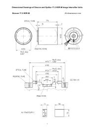
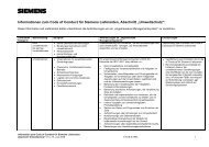
Figure 3: Test device acc. ASTM E1742-00 Diagram 1: Test result acc. ASTM E1742-00<br />
<strong>SILAC®</strong><br />
<strong>Siemens</strong> <strong>Industrial</strong> <strong>Linear</strong> <strong>Accelerator</strong><br />
ASTM E1742-00:<br />
The following unit mold is placed between 2 plates made<br />
on 80 mm thick steel (Figure 3).<br />
The diagram shows the result which is generated with the<br />
6 MeV <strong>SILAC®</strong> (Diagram 1).<br />
D. System interface<br />
Control of the whole system is possible via an external<br />
user interface. This system software can be operated on a<br />
standard Windows computer at the customer site or by<br />
SPS System (24V TTL).<br />
All relevant parameters like energy, dose, repetition rate<br />
or pulse length are variable within the system limits.<br />
In order to start the beam pulse the user can choose<br />
between external triggering and internal trigger control.<br />
The system control is fully integrated and shows the<br />
user all status messages regarding time stamps, status of<br />
system and safety loops and system errors (Figure 4).<br />
E. Safety circuits<br />
The “beam off“ safety switch is realized by an emergency<br />
stop switch of cat. 4, which has to be lined in the radiation<br />
safety loop at the user site.<br />
The system has an interlock system. When activated<br />
the errors are shown on the user monitor and the affected<br />
components stop operation.<br />
After solving the problem, the beam operation can be<br />
continued.<br />
D<br />
C<br />
B<br />
3.0 FE – 80 mm steel<br />
F. Mechanical design<br />
The main design elements are made of aluminum<br />
or stainless steel.<br />
The standard configuration can be operated in the<br />
horizontal position only.<br />
Cooling system<br />
The system needs a DI water supply. This can be provided<br />
at the user end or by the supplier. The recommended<br />
indoor cooling system has the following dimensions:<br />
Width 480 mm, length 510 mm, height 560 mm<br />
Figure 4: Screenshot of user interface<br />
4