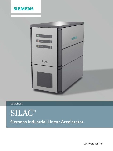
SILAC® Siemens Industrial Linear Accelerator
SILAC® Siemens Industrial Linear Accelerator
SILAC® Siemens Industrial Linear Accelerator

You also want an ePaper? Increase the reach of your titles
YUMPU automatically turns print PDFs into web optimized ePapers that Google loves.
Datasheet<br />
SILAC ®<br />
<strong>Siemens</strong> <strong>Industrial</strong> <strong>Linear</strong> <strong>Accelerator</strong><br />
Answers for life.
<strong>SILAC®</strong><br />
<strong>Siemens</strong> <strong>Industrial</strong> <strong>Linear</strong> <strong>Accelerator</strong><br />
The <strong>SILAC®</strong> <strong>Linear</strong> <strong>Accelerator</strong> System is designed for<br />
special Non Destructive Testing (NDT) applications and for<br />
usage in scanning devices for cargo and vehicles in the<br />
security sector.<br />
Stationary and mobile types are available with a variable<br />
set of energies in the range of 1 to 9 MeV photon radiation.<br />
The <strong>SILAC®</strong> System is a compact module, which includes<br />
all necessary components like linear accelerator, shielding,<br />
magnetron, high frequency modulator, power supplies,<br />
interfaces.<br />
Additional and optional components such as external<br />
supplies for hot and cold environment, or a collimator, are<br />
available.<br />
General information<br />
The system can be equipped with 2 types of linear accelerator<br />
for a wide energy range (6 MeV, 9 MeV maximum<br />
Energy). The actual energy level can be varied by means<br />
of software.<br />
The energy is defined by the maximum electron energy of<br />
the selected mode and generates a spectrum of photons<br />
according to the corresponding Bremsstrahlung.<br />
The modular design allows customized installations in a<br />
stationary environment in bunkers or control areas as well<br />
as mobile setups on trucks and non-stationary equipment.<br />
2<br />
Three main components are combined in one module<br />
design:<br />
◾ An accelerator section<br />
◾ An HF-generation section<br />
◾ A control and interface section<br />
On request, it’s possible to include collimators or additional<br />
low leakage shielding.<br />
Control of the entire system is possible by an external<br />
user interface. This system software can be operated on<br />
any standard Windows-computer or by SPS system on<br />
customer site.<br />
It is possible to vary many parameters at the software<br />
control console like electron energy, pulse width, repetition<br />
rate or beam current.<br />
The integrated sensors for temperature, dose rate or<br />
water flow and the predefined software and mode tables<br />
supervise the status of the system at all times and produce<br />
warning messages or trigger system interlocks to avoid<br />
hazardous situations.
Scanned 6 MeV <strong>Accelerator</strong> (SW by Volume Graphics GmbH)<br />
<strong>SILAC®</strong><br />
<strong>Siemens</strong> <strong>Industrial</strong> <strong>Linear</strong> <strong>Accelerator</strong><br />
Application / example for use:<br />
◾ Cargo scanning<br />
Trucks<br />
Ships<br />
Rails<br />
◾ NDT<br />
QM in casting technology<br />
Material inspections<br />
Reverse engineering<br />
Measuring of complex assemblies<br />
◾ Various research fields<br />
Technical data<br />
A. Power parameter<br />
The system is equipped with a linear electron accelerator,<br />
which accelerates through 3 GHz radiofrequency standing<br />
waves until the maximum electron energy from 1 to 9 MeV<br />
is reached, depending on the type of accelerator (other<br />
energies on request) (Figure 1).<br />
B. Cone beam 6 MeV<br />
The following dose values characterize the beam angle:<br />
15°: Dose ~ 50 % of center beam line<br />
45°: Dose ~ 9 % of center beam line<br />
C. Image quality<br />
Distinguishable wire diameter and distance of the<br />
double-wire penetrameter Phantom 5D are 320 µm,<br />
which corresponds to an image blur of 640 µm<br />
(Figure 2).<br />
Scanned turbine blade (SW by Fraunhofer IIS)<br />
Figure 1: <strong>Linear</strong> <strong>Accelerator</strong> 6 MeV<br />
6 max.<br />
10 max.<br />
17<br />
5 4 3,5 4,5<br />
3 5 (= 15) 4 4 (= 16)<br />
Figure 2: Test device (parameter: extension ~3,<br />
distance focus-detector = 76 cm, energy = 6 MeV)<br />
70<br />
5 3,5 (= 17,5)<br />
15<br />
3
.75<br />
F<br />
4T Dia. 1T Dia.<br />
A<br />
E<br />
2T Dia.<br />
FE<br />
T<br />
±10%<br />
Figure 3: Test device acc. ASTM E1742-00 Diagram 1: Test result acc. ASTM E1742-00<br />
<strong>SILAC®</strong><br />
<strong>Siemens</strong> <strong>Industrial</strong> <strong>Linear</strong> <strong>Accelerator</strong><br />
ASTM E1742-00:<br />
The following unit mold is placed between 2 plates made<br />
on 80 mm thick steel (Figure 3).<br />
The diagram shows the result which is generated with the<br />
6 MeV <strong>SILAC®</strong> (Diagram 1).<br />
D. System interface<br />
Control of the whole system is possible via an external<br />
user interface. This system software can be operated on a<br />
standard Windows computer at the customer site or by<br />
SPS System (24V TTL).<br />
All relevant parameters like energy, dose, repetition rate<br />
or pulse length are variable within the system limits.<br />
In order to start the beam pulse the user can choose<br />
between external triggering and internal trigger control.<br />
The system control is fully integrated and shows the<br />
user all status messages regarding time stamps, status of<br />
system and safety loops and system errors (Figure 4).<br />
E. Safety circuits<br />
The “beam off“ safety switch is realized by an emergency<br />
stop switch of cat. 4, which has to be lined in the radiation<br />
safety loop at the user site.<br />
The system has an interlock system. When activated<br />
the errors are shown on the user monitor and the affected<br />
components stop operation.<br />
After solving the problem, the beam operation can be<br />
continued.<br />
D<br />
C<br />
B<br />
3.0 FE – 80 mm steel<br />
F. Mechanical design<br />
The main design elements are made of aluminum<br />
or stainless steel.<br />
The standard configuration can be operated in the<br />
horizontal position only.<br />
Cooling system<br />
The system needs a DI water supply. This can be provided<br />
at the user end or by the supplier. The recommended<br />
indoor cooling system has the following dimensions:<br />
Width 480 mm, length 510 mm, height 560 mm<br />
Figure 4: Screenshot of user interface<br />
4
Main Customer Benefits<br />
◾ Dual energy for enhanced material detection<br />
◾ Advanced energy selection for wide range of<br />
applications and samples<br />
◾ Adjustable operation scheme<br />
Pulse length<br />
Pulse repetition rate<br />
Dose rate<br />
Energy<br />
Configuration –<br />
Customizing<br />
Size H [cm]<br />
W [cm]<br />
D [cm]<br />
Leakage radiation weight Ratio 90° to central beam in<br />
1 m distance p weight [kg]<br />
Max. dose rate<br />
(measured in water,<br />
1 m distance)<br />
1 MeV [Gy/min]<br />
2 MeV [Gy/min]<br />
3 MeV [Gy/min]<br />
4 MeV [Gy/min]<br />
6 MeV [Gy/min]<br />
9 MeV [Gy/min]<br />
◾ Flexible customer design<br />
Separate accelerator section available<br />
“All in one box“ for easy installation<br />
◾ Compact size and optimized weight<br />
◾ Fully digital control with solid state power section<br />
◾ Variable shielding options<br />
◾ Different primary collimation options possible<br />
Stationary Compact<br />
6 MeV 9 MeV 6 MeV 9 MeV<br />
196<br />
101<br />
193<br />
10 -6 p On request<br />
10 -3 p 2600<br />
0.2<br />
0.5<br />
1.8<br />
3<br />
9<br />
–<br />
196<br />
101<br />
193<br />
10 -6 p On request<br />
2 x 10 -3 p 2200<br />
–<br />
–<br />
–<br />
3<br />
9<br />
16<br />
On request On request<br />
10 -6 p On request 10 -6 p On request<br />
Focal spot size [mm] < 2 < 2 < 2 < 2<br />
Variable pulse adjustment Repetition rate [Hz]<br />
Pulse length [µs]<br />
Environment for usage Temperature [°C]<br />
(other temperatures on request)<br />
Rel. humidity [%]<br />
Protection class [IP rating]<br />
Impact resistance<br />
Vibrations<br />
Interfaces to customer:<br />
• Electrical power<br />
TN-S supply with CEE plug<br />
stucked IP66<br />
• Communications<br />
for interlock-system<br />
status indication, 24 V<br />
TTL activation and<br />
triggering ethernet<br />
ext. control and<br />
trigger under reserve<br />
• Cooling system<br />
plugs<br />
(for customer equipment)<br />
Voltage [VAC]<br />
Current [A]<br />
1 x 15-pin SUB-D stucked IP66<br />
1 x 25-pin SUB-D stucked IP66<br />
1 x RJ45 Cat6 stucked IP66<br />
4 x 5V TNC stucked IP66<br />
1 x 9-pin SUB-D stucked IP66<br />
Pressure [bar]<br />
Temperature [°C]<br />
Water flow [l/min]<br />
Image quality DIN EN 462-5<br />
ASTM 1742-00<br />
20-300<br />
1-4 µs<br />
10-30<br />
10-85<br />
66<br />
20 g<br />
2 g<br />
400<br />
32<br />
Yes<br />
Yes<br />
Yes<br />
Yes<br />
Yes<br />
5-6<br />
16-30<br />
30-40<br />
See above<br />
See above<br />
20-300<br />
1-4 µs<br />
10-30<br />
10-85<br />
66<br />
20 g<br />
2 g<br />
400<br />
32<br />
Yes<br />
Yes<br />
Yes<br />
Yes<br />
Yes<br />
5-6<br />
16-30<br />
30-40<br />
See above<br />
See above<br />
0.2<br />
0.5<br />
1.8<br />
3<br />
9<br />
–<br />
20-300<br />
1-4 µs<br />
10-30<br />
10-85<br />
66<br />
20 g<br />
2 g<br />
400<br />
32<br />
Yes<br />
Yes<br />
Yes<br />
Yes<br />
Yes<br />
5-6<br />
On request<br />
On request<br />
See above<br />
See above<br />
Power consumption Power [kW] 15 15 15 15<br />
<strong>SILAC®</strong> <strong>SILAC®</strong> control and power unit<br />
<strong>SILAC®</strong> RF-unit<br />
<strong>SILAC®</strong> accelerator unit<br />
Mechanical components Collimator internal<br />
Adjusted aperture<br />
Controls and operation Dual energy switch – interlaced<br />
User interface and control software<br />
Others Installation and system integration<br />
R&D package<br />
Standards and Laws<br />
All <strong>SILAC®</strong> models are designed and manufactured<br />
in accordance with:<br />
All in One All in One<br />
On request<br />
On request<br />
On request<br />
Yes<br />
Yes<br />
On request<br />
On request<br />
On request<br />
On request<br />
Yes<br />
Yes<br />
On request<br />
Compact unit<br />
Separate<br />
radiation head<br />
On request<br />
On request<br />
Yes<br />
Yes<br />
Yes<br />
On request<br />
–<br />
–<br />
–<br />
3<br />
9<br />
16<br />
20-300<br />
1-4 µs<br />
10-30<br />
10-85<br />
66<br />
20 g<br />
2 g<br />
400<br />
32<br />
Yes<br />
Yes<br />
Yes<br />
Yes<br />
Yes<br />
5-6<br />
On request<br />
On request<br />
See above<br />
See above<br />
Compact unit<br />
Separate<br />
radiation head<br />
On request<br />
On request<br />
Yes<br />
Yes<br />
Yes<br />
On request<br />
Low Voltage Directive 2006/95/EC and EMC<br />
Directive 2004/108/EC (EC Declaration of Conformity),<br />
other regulations on request<br />
5
The <strong>Siemens</strong> Healthcare Business<br />
Unit Components & Vacuum Technology<br />
is ISO 9001 and ISO 13485<br />
certified, manufactures in accordance<br />
with the Quality System Regulations<br />
(QSR) as defined by the U.S. Food<br />
and Drug Administration (FDA) and<br />
endeavors to comply with legal<br />
requirements concerning the environmental<br />
compatibility of its products.<br />
<strong>Siemens</strong> reserves the right to modify<br />
the design and specifications contained<br />
herein without prior notice.<br />
All rights reserved, particularly in<br />
connection with patent applications<br />
or registrations of utility model or<br />
design. This document is not considered<br />
to be a contractual specification.<br />
Kindly contact <strong>Siemens</strong> AG prior<br />
to using this information for equipment<br />
design.<br />
Local Contact Information<br />
<strong>Siemens</strong> AG<br />
Healthcare Sector<br />
H CP CV OEM<br />
Henkestr. 127<br />
DE-91052 Erlangen<br />
Germany<br />
Phone: +49 9131 84-6911<br />
Fax: +49 9131 84-2501<br />
oem.healthcare@siemens.com<br />
Global <strong>Siemens</strong> Headquarters<br />
<strong>Siemens</strong> AG<br />
Wittelsbacherplatz 2<br />
80333 Muenchen<br />
Germany<br />
These components and configurations<br />
are not finished devices. Compliance<br />
with all laws and regulations that are<br />
applicable to finished devices is the<br />
responsibility of the assembler/manufacturer<br />
of the finished device.<br />
The information in this document<br />
contains general descriptions of the<br />
technical options available, which do<br />
not always have to be present in<br />
individual cases. The required features<br />
should therefore be specified in each<br />
individual case at the time of closing<br />
the contract.<br />
Global <strong>Siemens</strong> Healthcare<br />
Headquarters<br />
<strong>Siemens</strong> AG<br />
Healthcare Sector<br />
Henkestrasse 127<br />
91052 Erlangen<br />
Germany<br />
Phone: +49 9131 84-0<br />
www.siemens.com/healthcare<br />
Legal Manufacturer<br />
<strong>Siemens</strong> AG<br />
Wittelsbacherplatz 2<br />
DE-80333 Muenchen<br />
Germany<br />
Printed in Germany | CC 230 04120.2 | 10306993_DS_SILAC 2012-04 | © 04.2012, <strong>Siemens</strong> AG<br />
www.siemens.com/healthcare<br />
Global Business Unit<br />
<strong>Siemens</strong> AG<br />
Medical Solutions<br />
Components and Vacuum Technology<br />
Henkestr. 127<br />
DE-91052 Erlangen<br />
Germany<br />
Phone: +49 9131 84-0<br />
www.siemens.com/oemproducts<br />
The components are labeled as<br />
“Manufactured by <strong>Siemens</strong>”.<br />
However, the buyer shall not market<br />
the components using the “<strong>Siemens</strong>”<br />
brand name and/or trademark. The<br />
buyer may integrate these components<br />
into a system using its own<br />
brands and labels. The product names<br />
and/or brands referred to are the<br />
property of their respective trademark<br />
holders.