DocLib_42_0-4905 ArcMaster 400MST CE.pdf - Victor Technologies ...
DocLib_42_0-4905 ArcMaster 400MST CE.pdf - Victor Technologies ...
DocLib_42_0-4905 ArcMaster 400MST CE.pdf - Victor Technologies ...

Create successful ePaper yourself
Turn your PDF publications into a flip-book with our unique Google optimized e-Paper software.
7<br />
4<br />
3<br />
SECTION 5: SEQUEN<strong>CE</strong> OF OPERATION<br />
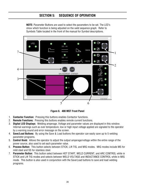
NOTE: Parameter Buttons are used to select the parameters to be set. The LED’s<br />
show which function is being adjusted on the weld sequence graph. Refer to<br />
Symbols Table located in the front of the manual for Symbol descriptions.<br />
5 6<br />
Figure 6. 400 MST Front Panel<br />
1. Contactor Function: Pressing this buttons enables Contactor functions.<br />
2. Remote Functions: Pressing this buttons enables remote current functions.<br />
3. Digital LED Displays: Welding amperage, Voltage and parameter values are displayed in this window.<br />
Internal warnings such as over temperature, low or high input voltage applied are signaled to the operator<br />
by a warning sound and error message on the screen.<br />
4. Save/Load Buttons: By using the Save & Load buttons the operator can easily save up to 5 welding<br />
parameter programs.<br />
5. Control Knob: Allows the operator to adjust the output amperage/voltage within the entire range of the<br />
power source, also used to set each parameter value.<br />
6. Process Button: This button selects between STICK, Lift TIG, and MIG modes. MIG modes include MS for<br />
mild steel and SS for stainless steel.<br />
7. Parameter Button: This button select between HOT START, WELD CURRENT, and ARC CONTROL while in<br />
STICK and Lift TIG modes and selects between WELD VOLTAGE and INDUCTAN<strong>CE</strong> CONTROL while in MIG<br />
mode. This button is also used in conjunction with the Save/Load buttons to save and load welding<br />
programs.<br />
28<br />
1<br />
2