High aspect ratio micro/nano machining with proton beam writing
High aspect ratio micro/nano machining with proton beam writing
High aspect ratio micro/nano machining with proton beam writing

Create successful ePaper yourself
Turn your PDF publications into a flip-book with our unique Google optimized e-Paper software.
<strong>High</strong> <strong>aspect</strong> <strong>ratio</strong> <strong>micro</strong>/<strong>nano</strong> <strong>machining</strong><br />
<strong>with</strong> <strong>proton</strong> <strong>beam</strong> <strong>writing</strong><br />
M. Chatzichristidi, E. Valamontes, N. Tsikrikas, P. Argitis,<br />
I. Raptis<br />
Institute of Microelectronics, NCSR ‘Demokritos’ Athens, 15310<br />
Greece<br />
J.A.van Kan<br />
Engineering Science Programme and Centre for Ion Beam Applications<br />
(CIBA), National University of Singapore, Singapore<br />
F. Zhang, F. Watt<br />
Centre for Ion Beam Applications (CIBA), Physics Dept. National<br />
University of Singapore, Singapore<br />
mchatz@imel.demokritos.gr, raptis@imel.demokritos.gr
Proposed approach<br />
Develop a resist formulation suitable for<br />
Formation of thick films<br />
<strong>High</strong> resolution structures<br />
<strong>High</strong> Aspect <strong>ratio</strong><br />
<strong>High</strong> sensitivity<br />
Processing compatible <strong>with</strong> Standard Silicon processes<br />
Stripping <strong>with</strong> conventional stripping schemes<br />
Develop a patterning technology suitable for<br />
Fast prototyping<br />
Thick polymer film structuring<br />
<strong>High</strong> resolution patterning<br />
MNE 07 Copenhagen, Denmark<br />
25 September 2007
Presentation Outline<br />
• Conventional HAR Patterning Technologies<br />
X-Ray lithography (XR-LIGA)<br />
I-line lithograpy (UV-LIGA)<br />
• Proton Beam Writing (PBW)<br />
Principle of ope<strong>ratio</strong>n<br />
Advantages & disadvantages<br />
Typical results<br />
• Typical HAR Resists<br />
PMMA<br />
SU-8<br />
• TADEP resist<br />
Formulation<br />
Physicochemical properties<br />
Formulation & processing optimization<br />
Lithographic results<br />
Electroplating<br />
• PBW simulation<br />
Simulation of Proton <strong>beam</strong> – Matter interaction<br />
Simulation of the thick polymeric films patterning<br />
• Conclusions<br />
MNE 07 Copenhagen, Denmark<br />
25 September 2007
Presentation Outline<br />
• Conventional HAR Patterning Technologies<br />
X-Ray lithography (XR-LIGA)<br />
I-line lithograpy (UV-LIGA)<br />
• Proton Beam Writing (PBW)<br />
Principle of ope<strong>ratio</strong>n<br />
Advantages & disadvantages<br />
Typical results<br />
• Typical HAR Resists<br />
PMMA<br />
SU-8<br />
• TADEP resist<br />
Formulation<br />
Physicochemical properties<br />
Formulation & processing optimization<br />
Lithographic results<br />
Electroplating<br />
• PBW simulation<br />
Simulation of Proton <strong>beam</strong> – Matter interaction<br />
Simulation of the thick polymeric films patterning<br />
• Conclusions
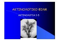
UV-LIGA (typical literature results)<br />
SEM photos of SU-8 <strong>micro</strong>structure <strong>with</strong><br />
thickness of 400 µm.<br />
Linewidth: 10 µm<br />
X. Tian, G. Liu, Y. Tian, P. Zhang, X. Zhang<br />
Micros. Techn. 11 265(2005)<br />
J. Liu, B. Cai, J. Zhu, G. Ding, X. Zhao, C. Yang, D. Chen<br />
Micros. Tech. 10 265(2004)<br />
SU-8 patterns <strong>with</strong><br />
thickness 210 µm, width 10 µm<br />
Aspect <strong>ratio</strong> is 21.<br />
MNE 07 Copenhagen, Denmark<br />
25 September 2007
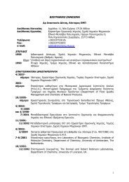
X-Ray LIGA (typical literature results)<br />
Three-level SU-8 structure <strong>with</strong> step heights<br />
of 300, 600 and 900 µm fabricated by X-ray<br />
lithography.<br />
J. Hormes, J. Göttert, K. Lian, Y. Desta, L.<br />
Jian Nucl. Instr. Meth. B 199 332(2003)<br />
1500 µm tall SU-8 gears.<br />
MNE 07 Copenhagen, Denmark<br />
25 September 2007
Proton Beam Writing (PBW) (I)<br />
Comparison between p-<strong>beam</strong> <strong>writing</strong>,<br />
FIB, and (c) e-<strong>beam</strong> <strong>writing</strong>. The p-<strong>beam</strong><br />
and e-<strong>beam</strong> images were simulated using<br />
SRIM and CASINO software packages,<br />
respectively.<br />
F.Watt, M.B.H.Breese, A.A.Bettiol, J.A.van Kan<br />
Materials Today 10(6) 20(2007)<br />
Schematic of the p-<strong>beam</strong> <strong>writing</strong> facility at<br />
CIBA. MeV <strong>proton</strong>s are produced in a <strong>proton</strong><br />
accelerator, and a demagnified image of the<br />
<strong>beam</strong> transmitted through an object<br />
aperture is focused onto the substrate<br />
material (resist) by means of a series of<br />
strong focusing magnetic quadrupole lenses.<br />
Beam scanning takes place using magnetic or<br />
electrostatic deflection before the focusing<br />
lenses.<br />
MNE 07 Copenhagen, Denmark<br />
25 September 2007
Proton Beam Writing (PBW) (II)<br />
Typical Application areas<br />
Photonics (waveguides, lens arrays, gratings, …)<br />
Microfluidic devices, biostructures, and biochips (imprinting, …)<br />
<strong>High</strong> resolution patterning (X-ray masks, …)<br />
Porous Si (patterning, Distributed Bragg reflectors, …)<br />
Advantages<br />
Maskless process (ideal for prototyping)<br />
Vertical side walls<br />
Ultra high resolution<br />
Ultra high <strong>aspect</strong> <strong>ratio</strong> pattering (provided the resist properties)<br />
Disadvantages<br />
Serial patterning process (moderate speed)<br />
Limited penet<strong>ratio</strong>n depth (50µm for 2MeV <strong>proton</strong> <strong>beam</strong>)<br />
MNE 07 Copenhagen, Denmark<br />
25 September 2007
Proton Beam Writing (PBW) (III)<br />
<strong>High</strong> <strong>aspect</strong> <strong>ratio</strong> test<br />
structures in SU-8 (60 nm<br />
wide, 10µm deep structures).<br />
First exposure<br />
Parthenon’s copy <strong>with</strong> a<br />
reduction of 1 million times<br />
Second exposure<br />
I.Rajta, M.Chatzichristidi, E.Baradács, I.Raptis,<br />
Nucl. Instrum. Meth. B 260 414(2007)<br />
J. A. van Kan, P. G. Shao,<br />
K. Ansari, A. A. Bettiol,<br />
T. Osipowicz, F. Watt,<br />
Microsyst Technol 13 431(2007)<br />
Side view of the<br />
“lambda” structures.<br />
MNE 07 Copenhagen, Denmark<br />
25 September 2007
Typical resists for HAR structures<br />
Positive resists<br />
PMMA<br />
Novolak-diazonaphtoquinone resist platform<br />
Negative resists<br />
epoxy based, chemically amplified SU-8<br />
MNE 07 Copenhagen, Denmark<br />
25 September 2007
PMMA (I)<br />
Advantages<br />
<strong>High</strong> resolution<br />
Stripping <strong>with</strong> conventional stripping schemes ( e.g. acetone)<br />
Disadvantages<br />
Limitation in the film thickness obtained by spin coating<br />
Low sensitivity<br />
Development in organic solvents (MIBK or MIBK/IPA)<br />
MNE 07 Copenhagen, Denmark<br />
25 September 2007
CH3 H2 C C<br />
n<br />
C O<br />
O<br />
CH 3<br />
PMMA<br />
PMMA thickness: 350 nm.<br />
Proton <strong>beam</strong>: 2MeV<br />
Structure’s width: 50nm<br />
PMMA (II)<br />
CH 3<br />
H 2<br />
C C<br />
C<br />
O<br />
OCH 3<br />
F. Watt, M.B.H. Breese, A.A. Bettiol, J.A.<br />
van Kan Materials Today 10(6) 20(2007)<br />
a)<br />
H 2<br />
C<br />
CH 3<br />
C<br />
C O<br />
OCH 3<br />
C<br />
H 2<br />
n<br />
CH 3<br />
C<br />
Chain Chain scission<br />
Cleavage Cleavage of methyl of methyl ester group<br />
CH 3<br />
hv H2 C C<br />
CH 3<br />
.<br />
Chain scission mechanism upon exposure<br />
H 2<br />
C<br />
CH 3<br />
C<br />
C O<br />
OCH 3<br />
CH2 + . C further reactions<br />
C O<br />
OCH 3<br />
n<br />
+<br />
Further reactions<br />
.<br />
C O<br />
OCH 3<br />
evolution of gaseous,<br />
volatile products:<br />
CO, CO2, . CH3, CH3O . Evolution of gaseous,<br />
Volatile products:<br />
CO, CO .<br />
2 , CH3 ,CH3O .<br />
SEM image of 5-μm thick PMMA by PBW<br />
at 1.7 MeV (fluence: 100 nC/mm 2 ) <strong>with</strong><br />
<strong>writing</strong> patterns of dots (1.25µm<br />
diameter).<br />
N. Uchiya, T. Harada, M. Murai,H. Nishikawa,<br />
J. Haga, T. Sato, Y. Ishii, T. Kamiya, Nucl.<br />
Instr. and Meth. in Phys. Res. B 260405(2007)<br />
MNE 07 Copenhagen, Denmark<br />
25 September 2007
Advantages<br />
<strong>High</strong> sensitivity<br />
Thick films by spin coating<br />
Disadvantages<br />
Development in organic solvent<br />
SU-8 resist (I)<br />
Very difficult stripping by conventional<br />
stripping schemes (needs piranha etch,<br />
plasma ash e.t.c.)<br />
Absorption<br />
www.<strong>micro</strong>chem.com MNE 07 Copenhagen, Denmark<br />
25 September 2007
H 3C<br />
H 2C<br />
O<br />
O<br />
C<br />
H<br />
C CH 3<br />
O<br />
C<br />
H 2<br />
CH 2<br />
O<br />
C<br />
H<br />
H 2<br />
C<br />
CH 2<br />
H 3C<br />
H 2C<br />
O<br />
O<br />
C<br />
H<br />
C CH 3<br />
O<br />
CH 2<br />
O<br />
C C<br />
H2 H<br />
H 2<br />
C<br />
CH 2<br />
SU-8 resist (II)<br />
Chemical formulation of SU-8 resist<br />
H 3C<br />
H 2C<br />
O<br />
O<br />
C<br />
H<br />
C CH 3<br />
O<br />
C<br />
H 2<br />
CH 2<br />
O<br />
C<br />
H<br />
H 2<br />
C<br />
CH 2<br />
H 3C<br />
H 2C<br />
O<br />
O<br />
C<br />
H<br />
C CH 3<br />
O<br />
O<br />
C C<br />
H2 H<br />
CH 2<br />
CH 2<br />
Crosslinking mechanism<br />
+<br />
S +<br />
S<br />
F<br />
F<br />
F Sb F<br />
F F<br />
OPEN OF EPOXY RINGS<br />
AND BONDING
SU-8 resist (characteristic PBW results)<br />
1 mm 2 area of single pixel<br />
irradiation on SU-8 (top view).<br />
I.Rajta, M.Chatzichristidi, E.Baradács,<br />
I.Raptis, Nucl. Instrum. Meth. B 260<br />
414(2007)<br />
Side view of irradiation on SU-8.<br />
130 nm wide lines, 15 <strong>aspect</strong> <strong>ratio</strong><br />
J.A. van Kan, P.G. Shao, K. Ansari,<br />
A.A. Bettiol, T. Osipowicz F. Watt,<br />
Microsyst. Technol. 13 431(2007)<br />
MNE 07 Copenhagen, Denmark<br />
25 September 2007
Presentation Outline<br />
• Conventional HAR Patterning Technologies<br />
X-Ray lithography (XR-LIGA)<br />
I-line lithograpy (UV-LIGA)<br />
• Proton Beam Writing (PBW)<br />
Principle of ope<strong>ratio</strong>n<br />
Advantages & disadvantages<br />
Typical results<br />
• Typical HAR Resists<br />
PMMA<br />
SU-8<br />
• TADEP resist<br />
Formulation<br />
Physicochemical properties<br />
Formulation & processing optimization<br />
Lithographic results<br />
Electroplating<br />
• PBW simulation<br />
Simulation of Proton <strong>beam</strong> – Matter interaction<br />
Simulation of the thick polymeric films patterning<br />
• Conclusions
Thick Aqueous Developable EPoxy resist<br />
TADEP formulation<br />
Goal:<br />
Develop a resist formulation suitable for<br />
•Formation of thick films<br />
•<strong>High</strong> resolution structures<br />
•<strong>High</strong> Aspect <strong>ratio</strong><br />
•<strong>High</strong> sensitivity<br />
•Processing compatible <strong>with</strong> Standard Silicon process<br />
•Stripping <strong>with</strong> conventional stripping schemes<br />
MNE 07 Copenhagen, Denmark<br />
25 September 2007
[ CH CH2 ]<br />
OH<br />
TADEP formulation<br />
[ CH<br />
n CH2 ] m<br />
OH<br />
Partially Hydrogenated PHS<br />
from Maruzen Co.<br />
S +<br />
F<br />
F<br />
F Sb<br />
F F<br />
F<br />
Triphenyl Sulfonium Hexafluoro<br />
Antimonate (TPS-SbF 6 )<br />
[<br />
O<br />
Epoxy novolac<br />
Fractionation of EPICOTE 164 from Shell<br />
O<br />
F<br />
+<br />
S<br />
O<br />
S O<br />
F<br />
F<br />
CH 3<br />
OH<br />
1-(4-hydroxy-3-methylphenyl)<br />
tetrahydrothiophenium triflate<br />
(o-CS-triflate)<br />
MNE 07 Copenhagen, Denmark<br />
25 September 2007<br />
O
TADEP Crosslinking mechanism<br />
OH OH OH OH OH OH OH OH<br />
* *<br />
n<br />
OH OH<br />
OH OH OH OH OH OH OH OH<br />
* *<br />
n<br />
OH OH<br />
OH<br />
OH<br />
*<br />
O<br />
O<br />
OH<br />
OH<br />
O<br />
OH<br />
O<br />
Unexposed Resist Areas: Soluble in<br />
aqueous base developers<br />
R 1<br />
O<br />
C<br />
H<br />
Crosslinking<br />
CH 2<br />
OH<br />
R 1<br />
n*<br />
CH<br />
OH<br />
OH<br />
H + SbF 6 -<br />
H<br />
O<br />
CH 2<br />
O + H<br />
R 2<br />
OH<br />
OH<br />
OH<br />
OH<br />
R 1<br />
H<br />
O<br />
CH2 +<br />
C<br />
H<br />
H + , heating<br />
R 1<br />
CH<br />
H<br />
O<br />
CH 2<br />
O<br />
R 2<br />
OH OH OH OH OH OH OH OH<br />
* *<br />
n<br />
R 2<br />
OH OH<br />
OH OH<br />
HO<br />
O<br />
OH OH OH OH OH<br />
* *<br />
n<br />
+<br />
OH<br />
OH OH<br />
OH OH O OH<br />
*<br />
OH<br />
O<br />
OH<br />
O<br />
n*<br />
Exposed Resist Areas: Insoluble in<br />
aqueous base developers<br />
R 1<br />
C<br />
H<br />
H<br />
H + SbF 6 -<br />
O<br />
CH2 +<br />
Lewis acid<br />
regene<strong>ratio</strong>n<br />
OH<br />
R 1<br />
OH<br />
OH<br />
CH<br />
H<br />
O<br />
CH 2<br />
OH<br />
O + H<br />
R 2<br />
OH<br />
OH<br />
OH<br />
MNE 07 Copenhagen, Denmark<br />
25 September 2007
Absorbance (A)<br />
0.8<br />
0.7<br />
0.6<br />
0.5<br />
0.4<br />
0.3<br />
0.2<br />
0.1<br />
PAG’s UV spectra<br />
Thickness- Absorption data<br />
0.0<br />
300 320 340 360 380 400<br />
Wavelenght (nm)<br />
o-Cs Triflate<br />
TPS Antimonate<br />
365 nm<br />
It is shown that at 365nm, where<br />
the film is exposed, the TPSantimonate<br />
does not absorb<br />
whereas o-Cs triflate absorbs<br />
slightly.<br />
Film Thickness (μm)<br />
TADEP film thickness (after PAB)<br />
vs. spinning speed<br />
60<br />
50<br />
40<br />
30<br />
20<br />
10<br />
0<br />
45% TADEP<br />
30% TADEP<br />
500 1000 1500 2000 2500 3000 3500 4000 4500 5000<br />
Spinning speed (rpm)<br />
55µm thick film can be achieved<br />
<strong>with</strong> one spinning<br />
MNE 07 Copenhagen, Denmark<br />
25 September 2007
Rev Heat Flow (W/g)<br />
0 .4<br />
0 .3<br />
0 .2<br />
0 .1<br />
0 .0<br />
-0 .1<br />
-0 .2<br />
-0 .3<br />
-0 .4<br />
Glass transition temperature studies<br />
23.5°C (H )<br />
0.2129J/g/°C<br />
38.51°C (I)<br />
108.6°C (I)<br />
95.75°C (I)<br />
88.74°C (I)<br />
Epoxy<br />
134.74°C (I)<br />
0 50 1 00 1 50 2 0 0 2 50 30 0<br />
Exo U p Tem perature (°C )<br />
U niversal V3.9A TA Instrum ents<br />
PHS<br />
PHS-EP<br />
PHS-EP TPS Ant.<br />
unexposed<br />
PHS-EP TPS Ant.<br />
exposed<br />
PHS-EP o-Cs trifl.<br />
unexposed PHS-EP o-Cs trifl.<br />
exposed<br />
SU-8<br />
The resist components are fully miscible<br />
The exposed areas are crosslinked and show no Tg<br />
MNE 07 Copenhagen, Denmark<br />
25 September 2007
Dissolution study (PAG molecule)<br />
Concept: Controlled development<br />
process<br />
Tool: White Light Reflectance<br />
Spectroscopy DRM<br />
Thickness (nm)<br />
0<br />
0 60 120 180 240 300 360<br />
Film thickness: ~2μm<br />
Developer: AZ-726 (AZ-EM) 0.26N TMAH<br />
In all cases dissolution proceeds linearly <strong>with</strong> time.<br />
NO swelling effect is observed except in the UVI case which is very<br />
hydrophobic.<br />
In the SU-8 resist case, the development is abrupt (impossible to monitor).<br />
2100<br />
1800<br />
1500<br />
1200<br />
900<br />
600<br />
300<br />
Development time (sec)<br />
P-RES-4 “Processing effects on the dissolution properties of<br />
thin chemically amplified photoresist films”<br />
no PAG<br />
o-Cs Triflate 3.4%<br />
TPS Antimonate 5%<br />
TPS Triflate 4%<br />
UVI 6%<br />
TPS Ant. 2%<br />
TPS Ant. 3,2% o-Cs1.1%<br />
MNE 07 Copenhagen, Denmark<br />
25 September 2007
Laser<br />
n 1<br />
θ 1<br />
Detector<br />
n 2 z1<br />
resist<br />
n 3<br />
substrate<br />
θ 2<br />
Operating principle<br />
Single Wavelength<br />
Interferometer Set-up<br />
PAB study<br />
Intereference Signal (a.u.)<br />
0.90<br />
0.88<br />
0.86<br />
0.84<br />
0.82<br />
0.80<br />
0.78<br />
0.76<br />
Temperature<br />
Interference signal<br />
50 100 150 200<br />
Time (min)<br />
Solvent evapo<strong>ratio</strong>n during the PAB step. Most of the solvent<br />
evaporates during the first 10min (heat up from RT to 95 o C). During<br />
the rest period (4h) ~0.8μm of resist thinning is observed.<br />
100<br />
90<br />
80<br />
70<br />
60<br />
50<br />
40<br />
30<br />
Temperature ( o C)<br />
MNE 07 Copenhagen, Denmark<br />
25 September 2007
a<br />
100°C for 8 min<br />
exposure dose (238 nC/mm 2 )<br />
PEB study<br />
The increased PEB temperature helps<br />
significantly the crosslinking reaction<br />
b<br />
110°C for 8 min<br />
exposure dose (116 nC/mm 2 )<br />
Ι. Rajta, E. Baradacs, M. Chatzichristidi, E.S. Valamontes, I. Raptis,<br />
Nucl. Inst. Meth. B, 231 423 (2005)<br />
MNE 07 Copenhagen, Denmark<br />
25 September 2007
Preliminary Lithographic evaluation (I)<br />
UV-LIGA<br />
Thickness = 11 µm<br />
Aspect Ratio = 7<br />
Substrate: Silicon wafer <strong>with</strong> plating base (Au surface)<br />
I-line lithography (MJB3 Karl-Suss)<br />
Thickness = 35 µm<br />
Layout = 5 µm L/S<br />
Linewidth = 5 µm<br />
MNE 07 Copenhagen, Denmark<br />
25 September 2007
Preliminary Lithographic evaluation (II)<br />
SINGLE PIXEL AND SINGLE LINE EXPOSURES<br />
The achieved smallest feature size was the same as the measured <strong>beam</strong> spot size (limited by<br />
the <strong>proton</strong> <strong>beam</strong> dimensions). The highest <strong>aspect</strong> <strong>ratio</strong> for this type of structures was 7<br />
(for the selected film thickness).<br />
Side view of single pixel<br />
irradiation on TADEP.<br />
Resolution 2.8µm<br />
Aspect <strong>ratio</strong> 7<br />
Top view of single line<br />
irradiation on TADEP.<br />
Beam size: ~ 3X3µm<br />
I.Rajta, M.Chatzichristidi, E.Baradács, I.Raptis,<br />
Nucl. Instrum. Meth. B 260 414(2007)<br />
MNE 07 Copenhagen, Denmark<br />
25 Sept. 2007
Lithographic Evaluation using fine p-<strong>beam</strong><br />
Top view of PBW double line<br />
irradiation on TADEP resist.<br />
Line width ~110nm in X-direction.<br />
Resist thickness ~2.0 µm<br />
Aspect <strong>ratio</strong>: 18<br />
Beam size: ~100X200nm<br />
Two pixels pass line<br />
Pitch: 1µm, 4µm<br />
110nm
Lithographic Evaluation (III)<br />
Side view of dense lines by<br />
2MeV PBW on TADEP resist.<br />
Resist thickness ~11.0 µm<br />
Beam size: ~100X200nm<br />
Two pixels pass line<br />
Pitch: 1µm, 4µm<br />
MNE 07 Copenhagen, Denmark<br />
25 September 2007
Lithographic Evaluation (IV)<br />
Top view of PBW double line<br />
irradiation on TADEP resist. Line<br />
width 280nm in X-direction.<br />
Side view of the pattern. Resist<br />
thickness 12µm, <strong>aspect</strong> <strong>ratio</strong>: 42.<br />
Beam size: 200nm in X-direction<br />
MNE 07 Copenhagen, Denmark<br />
25 September 2007
Electroplating results<br />
167nm<br />
Side view of Ni plated on gold features.<br />
Ni thickness 0.8µm<br />
On the right side the resist pattern<br />
MNE 07 Copenhagen, Denmark<br />
25 September 2007
Presentation Outline<br />
• Conventional HAR Patterning Technologies<br />
X-Ray lithography (XR-LIGA)<br />
I-line lithograpy (UV-LIGA)<br />
• Proton Beam Writing (PBW)<br />
Principle of ope<strong>ratio</strong>n<br />
Advantages & disadvantages<br />
Typical results<br />
• Typical HAR Resists<br />
PMMA<br />
SU-8<br />
• TADEP resist<br />
Formulation<br />
Physicochemical properties<br />
Formulation & processing optimization<br />
Lithographic results<br />
Electroplating<br />
• PBW simulation<br />
Simulation of Proton <strong>beam</strong> – Matter interaction<br />
Simulation of the thick polymeric films patterning<br />
• Conclusions
PBW simulation flow-chart<br />
Point <strong>proton</strong> <strong>beam</strong> simulation<br />
Convolution <strong>with</strong> Gaussian Profile<br />
Realistic <strong>proton</strong> <strong>beam</strong> simulation<br />
Convolution <strong>with</strong> Layout<br />
Thermal processing,<br />
PEB simulation (only for CARs*)<br />
* P-RES5 “Stochastic simulation studies of molecular<br />
resists for the 32nm technology node”<br />
Energy (KeV/cm 3 *electron)<br />
10 15<br />
10 14<br />
10 13<br />
10 12<br />
10 11<br />
10 10<br />
10 9<br />
10 8<br />
10 7<br />
Point Beam Energy Deposition<br />
0 500 1000 1500 2000<br />
Radial distance (nm)<br />
Point Beam<br />
exposure<br />
Layout<br />
(top view)<br />
Energy deposition on resist Energy deposition<br />
(cross section)<br />
Development simulation<br />
Resist Profile<br />
(development)<br />
MNE 07 Copenhagen, Denmark<br />
25 September 2007
Proton Beam – matter interaction simulation<br />
The formalism adopted for simulating <strong>proton</strong>s propagation is that of TRIM /<br />
SRIM [1]. At high energies, we have decided, for the sake of the computer<br />
efficiency, to base the calculations on the Coulomb potential [2].<br />
Stopping powers at high energies were calculated according to Bethe’s<br />
theory<br />
At low energies, electronic stopping powers were obtained from experimental<br />
data, closely related to the empirical fitting formulas developed by Andersen<br />
and Ziegler.<br />
The nuclear stopping power, which is important only at very low energies, was<br />
obtained by the method of Everhart et al [3].<br />
[1] J. Biersack, L. Haggmark, Nucl. Instr. and Meth. 174 (1980) 257.<br />
[2] J. F. Ziegler, J. P. Biersack, U. Littmark, The Stopping and Range of Ions in Solids,<br />
The Stopping and Ranges of Ions in Matter, Vol. 1, Pergamon Press Inc., 1985.<br />
[3] Stopping Powers and Ranges for Protons and Alpha Particles, International<br />
Commission on Radiation Units and Measurements, Report 49, 1993.
Energy deposition (eV/Α)<br />
PBW simulation results (energy deposition)<br />
14<br />
12<br />
10<br />
8<br />
6<br />
4<br />
2<br />
Bulk PMMA<br />
10umPMMA/Si<br />
20umPMMA/Si<br />
30umPMMA/Si<br />
0<br />
0 5 10 15 20 25 30 35 40 45 50 55 60 65<br />
Depth (μm)<br />
Monte-Carlo (MC) simulation:<br />
Energy deposition vs. depth for<br />
various resist films.<br />
Proton <strong>beam</strong>: 2MeV<br />
Simulation Dz=50nm<br />
PMMA<br />
Si substrate<br />
Energy deposition (eV/Α)<br />
12<br />
10<br />
8<br />
6<br />
4<br />
2<br />
Literature<br />
SRIM<br />
Bulk PMMA<br />
0<br />
0 5 10 15 20 25 30 35 40 45 50 55 60 65 70<br />
Depth (μm)<br />
Comparison of the MC simulation<br />
results in bulk <strong>with</strong> the literature<br />
and SRIM<br />
Proton <strong>beam</strong>: 2MeV<br />
Simulation Dz=50nm<br />
MNE 07 Copenhagen, Denmark<br />
25 September 2007
PBW simulation results (convolution)<br />
Energy (KeV/cm 3 *electron)<br />
10 15<br />
10 14<br />
10 13<br />
10 12<br />
10 11<br />
10 10<br />
10 9<br />
10 8<br />
10 7<br />
Convoluted Energy Deposition<br />
Point Beam Energy Deposition<br />
0 500 1000 1500 2000<br />
Radial distance (nm)<br />
Energy deposition due to point <strong>beam</strong> and gaussian <strong>proton</strong> <strong>beam</strong> at<br />
the resist (10μm)/substrate interface (Beam diameter 100nm)<br />
MNE 07 Copenhagen, Denmark<br />
25 September 2007
PBW simulation results (layout level)<br />
Proton <strong>beam</strong> irradiated<br />
Unexposed area<br />
200nm lines / 400nm spaces<br />
Proton Beam Diameter 100nm<br />
Film Thickness 10µm<br />
Top view<br />
(layout)<br />
Si wafer Si wafer<br />
Threshold: 0.01 x G Threshold: 0.1 x G<br />
Energy deposition<br />
(cross section)<br />
Cross-section<br />
after development<br />
(simulation)<br />
MNE 07 Copenhagen, Denmark<br />
25 September 2007
Conclusions<br />
Proton Beam Writing proved a powerful <strong>micro</strong>/<strong>nano</strong> <strong>machining</strong><br />
tool, resolution depending on the <strong>beam</strong> size.<br />
The strippable, aqueous base developable TADEP resist proved<br />
adequate for high <strong>aspect</strong> <strong>ratio</strong> <strong>nano</strong><strong>machining</strong><br />
Dense features <strong>with</strong> vertical & smooth sidewalls were revealed:<br />
Thickness 2μμμμm, Linewidth 110nm, Aspect <strong>ratio</strong> 18<br />
Thickness 12μμμμm, Linewidth 280nm, Aspect Ratio 42<br />
Successful Ni electroplating is showed demonstrating the<br />
stripping capability of TADEP resist<br />
Simulation software for <strong>proton</strong> <strong>beam</strong> <strong>writing</strong> is under<br />
development<br />
MNE 07 Copenhagen, Denmark<br />
25 September 2007
Acknowledgments<br />
The work was financially supported by the<br />
PB.NANOCOMP project (funded by the Greek<br />
Secretariat for Research & Technology contract<br />
number 05-NONEU-467).<br />
THANK YOU FOR YOUR ATTENTION<br />
MNE 07 Copenhagen, Denmark<br />
25 September 2007