Mainboard D2464 - Fujitsu UK
Mainboard D2464 - Fujitsu UK
Mainboard D2464 - Fujitsu UK

You also want an ePaper? Increase the reach of your titles
YUMPU automatically turns print PDFs into web optimized ePapers that Google loves.
<strong>Mainboard</strong><br />
Short Description<br />
<strong>Mainboard</strong> <strong>D2464</strong><br />
Deutsch – English
Sie haben technische Fragen oder Probleme?<br />
Wenden Sie sich bitte an:<br />
● Ihren zuständigen Vertriebspartner oder Ihre Verkaufsstelle<br />
● unsere Hotline über das Kontaktformular unter www.fujitsu-siemens.com/support/contact/<br />
contact.html oder für Kunden, die ein einzelnes <strong>Mainboard</strong> gekauft haben: +49(0) 180 3777 005<br />
Aktuelle Informationen und Updates (z. B. BIOS-Update) zu unseren <strong>Mainboard</strong>s finden Sie im<br />
Internet: www.fujitsu-siemens.com/mainboards<br />
Are there any technical problems or other questions you need clarified?<br />
Please contact:<br />
● your sales partner or your sales outlet<br />
● unsere Hotline über das Kontaktformular unter www.fujitsu-siemens.com/support/contact/<br />
contact.html oder für Kunden, die ein einzelnes <strong>Mainboard</strong> gekauft haben: +49(0) 180 3777 005<br />
The latest information and updates (e.g. BIOS update) on our mainboards can be found on the<br />
Internet at: www.fujitsu-siemens.com/mainboards
Copyright © <strong>Fujitsu</strong> Siemens Computers GmbH 2006<br />
Intel, Pentium and Celeron are registered trademarks of Intel Corporation, USA.<br />
Microsoft, MS, MS-DOS and Windows are registered trademarks of Microsoft Corporation.<br />
PS/2 and OS/2 Warp are registered trademarks of International Business Machines, Inc.<br />
All other trademarks referenced are trademarks or registered trademarks of their respective<br />
owners, whose protected rights are acknowledged.<br />
All rights, including rights of translation, reproduction by printing, copying or similar methods,<br />
even of parts are reserved.<br />
Offenders will be liable for damages.<br />
All rights, including rights created by patent grant or registration of a utility model or design,<br />
are reserved. Delivery subject to availability.<br />
Right of technical modification reserved.
Dieses Handbuch wurde erstellt von/This manual was produced by<br />
Xerox Global Services<br />
Dieses Handbuch wurde auf Recycling-Papier gedruckt.<br />
This manual has been printed on recycled paper.<br />
Ce manuel est imprimé sur du papier recyclé.<br />
Este manual ha sido impreso sobre papel reciclado.<br />
Questo manuale è stato stampato su carta da riciclaggio.<br />
Denna handbok är tryckt på recyclingpapper.<br />
Dit handboek werd op recycling-papier gedrukt.<br />
Herausgegeben von/Published by<br />
<strong>Fujitsu</strong> Siemens Computers GmbH<br />
Printed in the Federal Republic of Germany<br />
AG 07/06<br />
Ausgabe/Edition 1<br />
Bestell-Nr./Order No.: A26361-<strong>D2464</strong>-Z110-1-7419
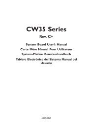
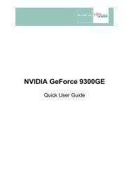
<strong>Mainboard</strong> D2264 - Internal connectors and slots<br />
Additional<br />
Power supply<br />
Fan 2<br />
PCI Express x16<br />
DVI<br />
PCI<br />
PCI 2<br />
PCI<br />
PCI 1<br />
PCI Express x1<br />
Power supply<br />
Battery<br />
Jumper<br />
Intrusion<br />
Slot 1<br />
Slot 2<br />
Slot 3<br />
Slot 4<br />
USB<br />
External<br />
speaker<br />
Fan 1<br />
IDEdrives<br />
1/2<br />
Floppy disc<br />
drive<br />
TPM<br />
SATA4<br />
SATA3<br />
SATA2<br />
SATA1<br />
Optionale Komponenten / Optional components<br />
External connectors front<br />
External connectors rear<br />
A26361-<strong>D2464</strong>-Z110-1-7419, Ausgabe 1<br />
USB - dual channel<br />
1<br />
2<br />
1 = VCC C<br />
2 = VCC D<br />
3 = Data negative C<br />
4 = Data negative D<br />
5 = Data positive C<br />
6 = Data positive D<br />
7 = GND<br />
8 = GND<br />
9 = Key<br />
10 = Not connected<br />
RiserCard (optional)<br />
1 = PCI slot 1<br />
2 = PCI slot 2<br />
E318<br />
1<br />
2
<strong>Mainboard</strong> <strong>D2464</strong><br />
List of onboard features <strong>D2464</strong>-A<br />
Chipset AMD AM2<br />
nVIDIA C51PVG/MCP51<br />
Board size proprietär / proprietary<br />
VGA <br />
Audio / 6-channel / S/PDIF / - / -<br />
Buzzer / int. Speaker Support - / <br />
LAN 1 Gbit / 100 Mbit / 10 Mbit / / <br />
LAN ASF / AoL / WoL / Boot - / - / / <br />
Serial-ATA2 / ATA / RAID / - / <br />
FireWire TM / USB 2.0 - / <br />
FAN monitored PSU** / CPU (FAN1) / AUX1 (FAN2) / AUX2 (FAN3) / / / -<br />
FAN controlled PSU** / CPU (FAN1) / AUX1 (FAN2) / AUX2 (FAN3) / / / -<br />
TEMP monitored CPU/ONB1/ONB2/HDD / / - / -<br />
SmartCard SystemLock (USB / serial) / -<br />
<strong>Fujitsu</strong> Siemens Computers Keyboard Power Button Support <br />
List of special onboard features<br />
Silent Fan / Silent Fan LT / -<br />
System Guard / Silent Drives / <br />
Recovery BIOS / Desk Update / Multi Boot / / <br />
Safe Standby / HDD Password / <br />
Logo Boot / Intel On Screen Branding / -<br />
** not supported by standard Power Supplies<br />
Special Features<br />
Green Edition Halogen-free and lead-reduced product<br />
Silent Fan Independent temperature related fan control<br />
System Guard View Silent Fan<br />
Silent Drives Noise reduction for optical and hard disk drives<br />
Recovery BIOS Restores a disrupted BIOS<br />
Desk Update Simple driver update with DU CD<br />
Multi Boot Comfortable boot from any boot device<br />
Power Supply Requirements - for onboard components (worst case)<br />
Source Voltage Maximal variation <strong>Mainboard</strong> current (Maximal) <strong>D2464</strong>-A<br />
+ 12 V +/– 5 % 11 A<br />
Main Power – 12 V +/– 10 % 0.05 A<br />
Supply + 5 V +/– 5 % 6.0 A<br />
+ 3.3 V +/– 5 % 2.0 A<br />
Aux. Power Supply + 5 V +/– 5 % 2 A<br />
A26361-<strong>D2464</strong>-Z110-1-7419, Ausgabe 1
<strong>Mainboard</strong> <strong>D2464</strong><br />
Hinweise zu Baugruppen<br />
Beachten Sie bei Baugruppen mit EGB unbedingt Folgendes:<br />
● Sie müssen sich statisch entladen (z. B. durch Berühren eines geerdeten<br />
Gegenstandes), bevor Sie mit Baugruppen arbeiten.<br />
● Verwendete Geräte und Werkzeuge müssen frei von statischer Aufladung sein.<br />
● Ziehen Sie den Netzstecker, bevor Sie Baugruppen stecken oder ziehen.<br />
● Fassen Sie die Baugruppen nur am Rand an.<br />
● Berühren Sie keine Anschluss-Stifte oder Leiterbahnen auf der Baugruppe.<br />
Eine Übersicht der Leistungsmerkmale finden Sie im Datenblatt!<br />
Besondere Merkmale<br />
Ihr <strong>Mainboard</strong> ist in verschiedenen Ausbaustufen erhältlich. Abhängig von der Konfiguration Ihres<br />
<strong>Mainboard</strong>s besitzt oder unterstützt das <strong>Mainboard</strong> bestimmte Merkmale.<br />
In diesem Handbuch finden Sie die wichtigsten Eigenschaften dieses <strong>Mainboard</strong>s beschrieben.<br />
Weitere Informationen zu <strong>Mainboard</strong>s finden Sie im Handbuch "Basisinformationen <strong>Mainboard</strong>" auf<br />
der CD "User Documentation" oder "OEM <strong>Mainboard</strong>" bzw. im Internet.<br />
Anschlüsse und Steckverbinder<br />
Die Position der Anschlüsse und Steckverbinder Ihres <strong>Mainboard</strong>s finden Sie am Anfang des<br />
Handbuches.<br />
Die markierten Komponenten und Steckverbinder müssen nicht auf dem <strong>Mainboard</strong> vorhanden sein.<br />
Externe Anschlüsse<br />
Die Position der externen Anschlüsse Ihres <strong>Mainboard</strong>s finden Sie am Anfang des Handbuches.<br />
LAN<br />
PS/2-Tastaturanschluss, violett<br />
(optional)<br />
LAN-Anschluss (RJ-45)<br />
Serielle Schnittstelle, türkis<br />
Mikrofonanschluss, rosa<br />
Audioeingang (Line in), hellblau USB – Universal Serial Bus, schwarz<br />
Audioausgang (Line out), hellgrün<br />
VGA, blau<br />
A26361-<strong>D2464</strong>-Z110-1-7419, Ausgabe 1 Deutsch - 1
<strong>Mainboard</strong> <strong>D2464</strong><br />
Grafikcontroller<br />
● Programmierbarer Shader-Model 3.0 DirectX 9 Grafik Prozessor<br />
● 300 MHz RAMDAC<br />
● TMDS-Schnittstelle für DVI-Bildschirm<br />
Auflösung (Farbtiefe bis zu 32 Bit/Pixel) Frequenz<br />
1024 x 768 (empfohlen / max*) 120 / 200 Hz<br />
1280 x 1024 (empfohlen / max*) 100 / 150 Hz<br />
1600 x 1200 (empfohlen / max*) 85 / 100 Hz<br />
1440 x 900 Widescreen TFT (VGA / DVI) x / x<br />
1680 x 1050 Widescreen TFT (VGA / DVI) x / x<br />
1920 x 1200 Widescreen TFT (VGA / DVI) x / x<br />
* maximale Bildwiederholrate für die Grafikeinstellung. Die<br />
Videoqualität kann verzerrt ("deteriorated") sein, wenn die<br />
Maximaleinstellung verwendet wird.<br />
2 - Deutsch A26361-<strong>D2464</strong>-Z110-1-7419, Ausgabe 1
<strong>Mainboard</strong> <strong>D2464</strong><br />
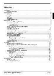
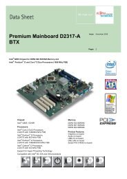
Prozessor ein- / ausbauen oder tauschen (mit Kühlkörper)<br />
!<br />
Für alle hier beschriebenen Arbeiten muss Ihr System vollständig von der Netzspannung<br />
getrennt sein! Nähere Angaben dazu finden Sie in der Betriebsanleitung Ihres Systems.<br />
Technische Daten<br />
● AMD Athlon 64/X2 und AMD Sempron mit bis zu 1 GHz Front Side Bus (Hypertransport) in der<br />
Bauform AM2 (mPGA 940)<br />
● Eine aktuelle Liste der von diesem <strong>Mainboard</strong> unterstützten Prozessoren finden Sie im Internet<br />
unter: www.fujitsu-siemens.com/mainboards.<br />
► Entfernen Sie einen eventuell vorhandenen Lüfter und den Kühlkörper.<br />
3<br />
1<br />
4 5<br />
2<br />
A<br />
► Drücken Sie den Hebel in Pfeilrichtung (1) und<br />
schwenken Sie ihn bis zum Anschlag nach<br />
oben (2).<br />
► Klappen Sie die Halterung nach oben.<br />
► Heben Sie den alten Prozessor aus dem<br />
Steckplatz (3).<br />
► Stecken Sie den neuen Prozessor so in den<br />
Steckplatz, dass die abgeschrägte Ecke des<br />
Prozessors mit der Codierung am Steckplatz (A)<br />
von der Lage her übereinstimmt (4).<br />
i<br />
Die abgeschrägte Ecke des Prozessors<br />
kann auch an einer anderen Stelle sein als<br />
in der Abbildung dargestellt.<br />
► Schwenken Sie den Hebel nach unten, bis er<br />
spürbar einrastet (5).<br />
!<br />
Bitte beachten Sie, dass je nach<br />
verwendetem Kühlkörper unterschiedliche<br />
Kühlkörperhalterungen auf dem <strong>Mainboard</strong><br />
benötigt werden.<br />
► Je nach Ausbau-Variante müssen Sie eine<br />
Schutzfolie vom Kühlkörper abziehen oder den<br />
Kühlkörper mit Wärmeleitpaste bestreichen, bevor<br />
Sie ihn aufsetzen.<br />
► Je nach Prozessor-Variante werden für die Befestigung des Kühlkörpers noch Klammern<br />
mitgeliefert, die den Kühlkörper fixieren.<br />
A26361-<strong>D2464</strong>-Z110-1-7419, Ausgabe 1 Deutsch - 3
<strong>Mainboard</strong> <strong>D2464</strong><br />
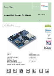
Hauptspeicher ein-/ausbauen oder tauschen<br />
Technische Daten<br />
Technologie: DDR2 400 / DDR2 533 / DDR2 667 / DDR2 800 ungepufferte DIMM Module<br />
240-Pin; 1,8 V; 64 Bit, ohne ECC<br />
Gesamtgröße: 64 MBytes bis 8 GByte DDR2<br />
Modulgrößen: 64, 128, 256, 512, 1024 oder 2048 MByte pro Modul<br />
Eine aktuelle Liste der für dieses <strong>Mainboard</strong> empfohlenen Speichermodule finden Sie im Internet<br />
unter: www.fujitsu-siemens.com/mainboards.<br />
Es muss mindestens ein Speichermodul eingebaut sein. Speichermodule mit unterschiedlicher<br />
Speicherkapazität können kombiniert werden.<br />
!<br />
i<br />
Es dürfen nur ungepufferte 1,8-V-Speichermodule ohne ECC verwendet werden.<br />
DDR2-Speichermodule müssen der PC2-3200U- oder PC2-4200U- oder PC2-5300U- oder<br />
PC2-6400U-Spezifikation entsprechen.<br />
Wenn Sie mehr als ein Speichermodul verwenden, dann achten Sie darauf, die<br />
Speichermodule auf beide Speicherkanäle aufzuteilen. Dadurch nutzen Sie die<br />
Performancevorteile des Dual-Channel-Mode.<br />
Die maximale Systemperformance ist gegeben, wenn in Channel A und Channel B die<br />
gleiche Speichergröße verwendet wird.<br />
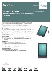
Um die Bestückung zu erleichtern, sind die Steckplätze (Slots) farbig gekennzeichnet.<br />
Wenn Sie die Speichermodule einstecken, beginnen Sie mit dem Steckplatz, der am<br />
weitesten vom Prozesser entfernt ist (Slot 4).<br />
Bei einer Speicherkonfiguration von 4 GByte kann der sichtbare und benutzbare<br />
Hauptspeicher auf bis zu 3,5 GByte reduziert sein (abhängig von der Konfiguration des<br />
Systems).<br />
Mehr als 4 GByte Hauptspeicher können nur mit entsprechendem Betriebssystem genutzt<br />
werden.<br />
4<br />
B<br />
Slot<br />
3<br />
A<br />
Channel<br />
2<br />
B<br />
1 A<br />
Anzahl der gesteckten Speichermodule<br />
zu verwendender Steckplatz 1 2 3 4<br />
Channel A, Slot 1 X<br />
Channel B, Slot 2 X X<br />
Channel A, Slot 3 X X X<br />
Channel B, Slot 4 X X X X<br />
Der Ein-/Ausbau ist im Handbuch "Basisinformationen <strong>Mainboard</strong>" beschrieben.<br />
4 - Deutsch A26361-<strong>D2464</strong>-Z110-1-7419, Ausgabe 1
<strong>Mainboard</strong> <strong>D2464</strong><br />
PCI-Bus-Interrupts – Auswahl des richtigen PCI-Steckplatzes<br />
Umfangreiche Informationen zu diesem Abschnitt finden Sie im Handbuch "Basisinformationen<br />
<strong>Mainboard</strong>".<br />
i<br />
Um optimale Stabilität, Performance und Kompatibilität zu erreichen, vermeiden Sie die<br />
mehrfache Nutzung von ISA IRQs oder PCI IRQ Lines (IRQ Sharing). Sollte IRQ Sharing<br />
nicht zu umgehen sein, so müssen alle beteiligten Geräte und deren Treiber IRQ Sharing<br />
unterstützen.<br />
Welche ISA IRQs den PCI IRQ Lines zugeordnet werden, wird normalerweise automatisch vom<br />
BIOS festgelegt (siehe Beschreibung "BIOS-Setup").<br />
Monofunktionale Erweiterungskarten<br />
PCI-/PCI-Express-Erweiterungskarten benötigen maximal einen Interrupt, der als PCI-Interrupt INT A<br />
bezeichnet wird. Erweiterungskarten, die keinen Interrupt benötigen, können in einen beliebigen<br />
Steckplatz eingebaut werden.<br />
A26361-<strong>D2464</strong>-Z110-1-7419, Ausgabe 1 Deutsch - 5
<strong>Mainboard</strong> <strong>D2464</strong><br />
Multifunktionale Erweiterungskarten oder Erweiterungskarten mit integrierter PCI-PCI Bridge<br />
Diese Erweiterungskarten benötigen bis zu vier PCI-Interrupts: INT A, INT B, INT C, INT D. Wie viele<br />
und welche dieser Interrupts verwendet werden, entnehmen Sie der mitgelieferten Dokumentation<br />
der Karte.<br />
Die Zuordnung der PCI-Interrupts zu den IRQ Lines finden Sie in der folgenden Tabelle:<br />
PCI<br />
INT<br />
LINE<br />
USB 1.1<br />
USB 2.0<br />
On board controller<br />
IDE<br />
SATA 0/1<br />
Controller or slot INT<br />
HD Audio<br />
LAN<br />
VGA<br />
Mechanical slot<br />
1 2 3 4 - - -<br />
PCIe x16<br />
PCIe x1<br />
PCI Slot<br />
1 2 - - -<br />
1 (A) X - - X X - - - - B A - - -<br />
2 (B) - X - - - - - - - A B - - -<br />
3 (C) - - - - - - - - - D C - - -<br />
4 (D) - - - - - X - - - C D - - -<br />
5 (E) - - - - - - - - - - - - -<br />
6 (F) - - - - - - - - - - - - -<br />
7 (G) - - - - - - - - - - - - -<br />
8 (H) - - - - - - - - - - - - -<br />
ID<br />
SEL<br />
- - - - - - - - - 21 23 - - -<br />
Dev# 0Bh 0Bh 0Dh 0Eh/0Fh 10h 14h 05h 02h 03h 05h 07h - - -<br />
Func<br />
tion#<br />
0 1 0 0 1 0 0 0 0 0 0 - - -<br />
Bus# 0 0 0 0 0 0 0 0 0 4 4 - - -<br />
* with onboard Grafic<br />
Verwenden Sie zuerst PCI-/PCI-Express-Steckplätze, die über eine einzige PCI IRQ Line verfügen<br />
(kein IRQ Sharing). Wenn Sie einen anderen PCI-/PCI-Express-Steckplatz mit IRQ Sharing<br />
benutzen müssen, überprüfen Sie, ob die Erweiterungskarte IRQ Sharing mit den anderen Geräten<br />
auf dieser PCI IRQ Line einwandfrei unterstützt. Auch die Treiber aller Karten und Komponenten an<br />
dieser PCI IRQ Line müssen IRQ Sharing unterstützen.<br />
6 - Deutsch A26361-<strong>D2464</strong>-Z110-1-7419, Ausgabe 1
BIOS-Update<br />
Wann sollte ein BIOS-Update durchgeführt werden?<br />
<strong>Mainboard</strong> <strong>D2464</strong><br />
<strong>Fujitsu</strong> Siemens Computers stellt neue BIOS-Versionen zur Verfügung, um die Kompatibilität zu<br />
neuen Betriebssystemen, zu neuer Software oder zu neuer Hardware zu gewährleisten. Außerdem<br />
können neue BIOS-Funktionen integriert werden.<br />
Ein BIOS-Update sollte auch immer dann durchgeführt werden, wenn ein Problem besteht, das sich<br />
durch neue Treiber oder neue Software nicht beheben lässt.<br />
Wo gibt es BIOS-Updates?<br />
Im Internet unter www.fujitsu-siemens.com/mainboards finden Sie die BIOS-Updates.<br />
Wie funktioniert ein BIOS-Update?<br />
Sie haben zwei Möglichkeiten:<br />
1. BIOS-Update unter DOS mit startfähiger BIOS-Update-Diskette - Kurzbeschreibung<br />
► Laden Sie die Update-Datei von unserer Internet-Seite auf Ihren PC.<br />
► Legen Sie eine leere Diskette (1,44 MByte) ein.<br />
► Führen Sie die Update-Datei aus (z. B. 2464103.EXE).<br />
► Es wird eine startfähige Update-Diskette erstellt. Lassen Sie diese Diskette im Laufwerk.<br />
► Starten Sie den PC neu.<br />
► Folgen Sie den Bildschirmanweisungen.<br />
i<br />
Detaillierte Informationen zum BIOS-Update unter DOS finden Sie im Handbuch zum<br />
"BIOS-Setup" (CD "Drivers & Utilities").<br />
2. BIOS-Update unter Windows mit dem Utility DeskFlash<br />
Ein BIOS-Update kann mit dem Utility DeskFlash auch direkt unter Windows durchgeführt werden.<br />
DeskFlash befindet sich auf der CD "Drivers & Utilities" (unter DeskUpdate).<br />
A26361-<strong>D2464</strong>-Z110-1-7419, Ausgabe 1 Deutsch - 7
<strong>Mainboard</strong> D2264<br />
Information about boards<br />
Be sure to observe the following for boards with ESD:<br />
● You must always discharge static build up (e.g. by touching a grounded object)<br />
before working.<br />
● The equipment and tools you use must be free of static charges.<br />
● Remove the power plug from the mains supply before inserting or removing<br />
boards containing ESDs.<br />
● Always hold boards with ESDs by their edges.<br />
● Never touch pins or conductors on boards fitted with ESDs.<br />
An overview of the features is provided in the data sheet.<br />
Special features<br />
Your mainboard is available in different configuration levels. Depending on the configuration, your<br />
mainboard is equipped with or supports special features.<br />
This manual describes the most important properties of this mainboard.<br />
Additional information on mainboards is contained in the manual "Basic information on mainboard"<br />
on the "User Documentation" or "OEM <strong>Mainboard</strong>" CDs, or on the Internet.<br />
Interfaces and connectors<br />
The location of the interfaces and connectors of your mainboard is specified at the beginning of the<br />
manual.<br />
The components and connectors marked are not necessarily present on the mainboard.<br />
External ports<br />
The location of the external connections of your mainboard is specified at the beginning of the<br />
manual.<br />
LAN<br />
PS/2 keyboard port, purple<br />
(optional)<br />
LAN port (RJ-45)<br />
Serial interface, turquoise<br />
Microphone jack (mono), pink<br />
Audio input (Line in), light blue USB - Universal Serial Bus, black<br />
Audio output (Line out), light green<br />
VGA, blue<br />
A26361-D2264-Z110-1-7419, edition 2 English - 1
<strong>Mainboard</strong> D2264<br />
Graphic Controller<br />
● Programmable shader model 3.0 DirectX 9 graphic processor<br />
● 300 MHz RAMDAC<br />
● TMDS interface for DVI screen<br />
Resolution (Colour depth up to 32 bit/pixel) Frequency<br />
1024 x 768 (recommended / max*) 120 / 200 Hz<br />
1280 x 1024 (recommended / max*) 100 / 150 Hz<br />
1600 x 1200 (redommended / max*) 85 / 100 Hz<br />
1440 x 900 Widescreen TFT (VGA / DVI) x / x<br />
1680 x 1050 Widescreen TFT (VGA / DVI) x / x<br />
1920 x 1200 Widescreen TFT (VGA / DVI) x / x<br />
* max. refresh rate for the graphic setting. When the max.<br />
setting is used the video quality may deteriorate.<br />
2 - English A26361-D2264-Z110-1-7419, edition 2
<strong>Mainboard</strong> D2264<br />
Installing/removing or replacing processor (with heat sink)<br />
!<br />
Disconnect the system from the mains voltage before performing any of the tasks<br />
described below. Details are contained in the operating manual of your system.<br />
Technical data<br />
● AMD Athlon 64/X2 and AMD Sempron with up to 1 GHz Front Side Bus (Hypertransport) in the<br />
AM2 (mPGA 940) design<br />
● A current list of the processors supported by this mainboard is available on the Internet at:<br />
www.fujitsu-siemens.com/mainboards.<br />
► Remove the fan that there may be and the heat sink.<br />
3<br />
1<br />
4 5<br />
2<br />
A<br />
► Pull the lever in the direction of the arrow (1) and<br />
lift it as far as it will go (2).<br />
► Fold up the frame.<br />
► Remove the old processor from the socket (3).<br />
► Insert the new processor in the socket so that the<br />
angled corner of the processor matches the<br />
coding on the socket (A) with regard to the<br />
position (4).<br />
i<br />
The angled corner of the processor can also<br />
be at a different location than shown in the<br />
illustration.<br />
► Push the lever back down until it clicks into<br />
place (5).<br />
!<br />
Please note that, depending on the heat<br />
sink used, different heat sink mounts are<br />
required on the mainboard.<br />
► Depending on the configuration variant, you must<br />
pull a protective foil off the heat sink or coat the<br />
heat sink with heat conducting paste before fitting<br />
it.<br />
► Depending on the processor variant, clips may also be supplied for mounting the heat sink that<br />
fix it in place.<br />
A26361-D2264-Z110-1-7419, edition 2 English - 3
<strong>Mainboard</strong> D2264<br />
Installing/removing or replacing main memory<br />
Technical data<br />
Technology: DDR2 400 / DDR2 533 / DDR2 667 and DDR2 800 unbuffered DIMM modules<br />
240-Pin; 1.8 V; 64 Bit, without ECC<br />
Size: 64 Mbytes to 8 Gbyte DDR<br />
Granularity: 64, 128, 256, 512, 1024 or 2048 Mbyte for one socket<br />
A current list of the memory modules recommended for this mainboard is available on the Internet<br />
at: www.fujitsu-siemens.com/mainboards.<br />
At least one memory module must be installed. Memory modules with different memory capacities<br />
can be combined.<br />
!<br />
i<br />
You may use only unbuffered 1.8 V memory modules without ECC.<br />
DDR2 memory modules must meet the PC2-3200U- or PC2-4200U- or PC2-5300U- or<br />
PC2-6400U-specification.<br />
If you use more than one memory module, then make sure to distribute the memory<br />
modules over both memory channels. By doing this you use the performance advantages<br />
of the dual-channel mode.<br />
The maximum system performance is given when the same memory size is used in<br />
Channel A and Channel B.<br />
To simplify equipping, the slots are colour coded.<br />
When inserting the memory modules start with the slot located the furthest away from the<br />
processor (slot 4).<br />
With a memory configuration of 4 Gbytes the visible and usable main memory can be<br />
reduced down to 3.5 Gbytes (depending on the system configuration).<br />
More than 4 GByte main memory can only be used with a corresponding operating<br />
system.<br />
4<br />
B<br />
Slot<br />
3<br />
A<br />
Channel<br />
2<br />
B<br />
1 A<br />
Number of inserted memory modules<br />
slot to be used 1 2 3 4<br />
Channel A, slot 1 X<br />
Channel B, slot 2 X X<br />
Channel A, slot 3 X X X<br />
Channel B, slot 4 X X X X<br />
The installation/removal is described in the "Basic information on mainboard" manual.<br />
4 - English A26361-D2264-Z110-1-7419, edition 2
PCI bus interrupts - Selecting correct PCI slot<br />
<strong>Mainboard</strong> D2264<br />
Extensive information on this section is contained in the manual "Basic information on mainboard".<br />
i<br />
To achieve optimum stability, performance and compatibility, avoid the multiple use of ISA<br />
IRQs or PCI IRQ Lines (IRQ sharing). Should IRQ sharing be unavoidable, then all<br />
involved devices and their drivers must support IRQ sharing.<br />
Which ISA IRQs are assigned to the PCI IRQ Lines is normally automatically specified by the BIOS<br />
(see "BIOS Setup" description).<br />
Monofunctional expansions cards<br />
PCI/PCI Express expansion cards require a maximum of one interrupt, which is called the PCI<br />
interrupt INT A. Expansion cards that do not require an interrupt can be installed in any desired slot.<br />
A26361-D2264-Z110-1-7419, edition 2 English - 5
<strong>Mainboard</strong> D2264<br />
Multifunctional expansion cards or expansion cards with integrated PCI-PCI bridge<br />
These expansion cards require up to four PCI interrupts: INT A, INT B, INT C, INT D. How many and<br />
which of these interrupts are used is specified in the documentation provided with the card.<br />
The assignment of the PCI interrupts to the IRQ Lines is shown in the following table:<br />
PCI<br />
INT<br />
LINE<br />
USB 1.1<br />
USB 2.0<br />
On board controller<br />
IDE<br />
SATA 0/1<br />
Controller or slot INT<br />
HD Audio<br />
LAN<br />
VGA<br />
Mechanical slot<br />
1 2 3 4 - - -<br />
PCIe x16<br />
PCIe x1<br />
PCI Slot<br />
1 2 - - -<br />
1 (A) X - - X X - - - - B A - - -<br />
2 (B) - X - - - - - - - A B - - -<br />
3 (C) - - - - - - - - - D C - - -<br />
4 (D) - - - - - X - - - C D - - -<br />
5 (E) - - - - - - - - - - - - -<br />
6 (F) - - - - - - - - - - - - -<br />
7 (G) - - - - - - - - - - - - -<br />
8 (H) - - - - - - - - - - - - -<br />
ID<br />
SEL<br />
- - - - - - - - - 21 23 - - -<br />
Dev# 0Bh 0Bh 0Dh 0Eh/0Fh 10h 14h 05h 02h 03h 05h 07h - - -<br />
Func<br />
tion#<br />
0 1 0 0 1 0 0 0 0 0 0 - - -<br />
Bus# 0 0 0 0 0 0 0 0 0 4 4 - - -<br />
* with onboard Grafic<br />
Use first PCI/PCI Express slots that have a single PCI IRQ Line (no IRQ sharing). If you must use<br />
another PCI/PCI Express slot with IRQ sharing, check whether the expansion card properly supports<br />
IRQ sharing with the other devices on this PCI IRQ Line. The drivers of all cards and components on<br />
this PCI IRQ Line must also support IRQ sharing.<br />
6 - English A26361-D2264-Z110-1-7419, edition 2
BIOS update<br />
When should a BIOS update be carried out?<br />
<strong>Mainboard</strong> D2264<br />
<strong>Fujitsu</strong> Siemens Computers makes new BIOS versions available to ensure compatibility to new<br />
operating systems, new software or new hardware. In addition, new BIOS functions can also be<br />
integrated.<br />
A BIOS update should always also be carried out when a problem exists that cannot be solved with<br />
new drivers or new software.<br />
Where can I obtain BIOS updates?<br />
The BIOS updates are available on the Internet at www.fujitsu-siemens.com/mainboards.<br />
How does a BIOS update work?<br />
You have two ways of doing this:<br />
1. BIOS update under DOS with bootable BIOS update floppy disk - brief description<br />
► Download the update file from out website to your PC.<br />
► Insert an empty floppy disk (1.44 Mbyte).<br />
► Run the update file (e.g. 2464103.EXE).<br />
► A bootable update floppy disk is created. Leave this floppy disk in the drive.<br />
► Restart the PC.<br />
► Follow the instructions on screen.<br />
i<br />
Detailed information on the BIOS update under DOS is provided in the manual on "BIOS<br />
Setup" ("Drivers & Utilities" CD).<br />
2. BIOS update under Windows with DeskFlash utility<br />
A BIOS update can also be carried out directly under Windows with the DeskFlash utility. DeskFlash is<br />
contained on the "Drivers & Utilities" CD (under DeskUpdate).<br />
A26361-D2264-Z110-1-7419, edition 2 English - 7