iTNC 530 - TNC 640 - DR. JOHANNES HEIDENHAIN GmbH
iTNC 530 - TNC 640 - DR. JOHANNES HEIDENHAIN GmbH
iTNC 530 - TNC 640 - DR. JOHANNES HEIDENHAIN GmbH

Create successful ePaper yourself
Turn your PDF publications into a flip-book with our unique Google optimized e-Paper software.
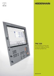
<strong>i<strong>TNC</strong></strong> <strong>530</strong><br />
The Versatile Contouring<br />
Control for Milling, Drilling,<br />
Boring Machines and<br />
Machining Centers<br />
September 2011
Uniformly Digital<br />
For over 35 years, <strong>TNC</strong> controls have been<br />
proving themselves in daily use on milling,<br />
drilling and boring machines, as well as<br />
machining centers. This success is due in<br />
part to their shop-oriented programmability,<br />
but also to their compatibility with<br />
programs of the predecessor models. Now<br />
<strong>HEIDENHAIN</strong> is introducing the <strong>i<strong>TNC</strong></strong> <strong>530</strong><br />
as a uniformly digital numerical control.<br />
In the uniformly digital control design of<br />
the <strong>i<strong>TNC</strong></strong> <strong>530</strong>, all components are<br />
connected to each other via purely digital<br />
interfaces: The control components are<br />
connected via HSCI (<strong>HEIDENHAIN</strong> Serial<br />
Controller Interface), the real-time protocol<br />
from <strong>HEIDENHAIN</strong> for Fast Ethernet, and<br />
the encoders are connected via EnDat 2.2,<br />
the bidirectional interface from<br />
<strong>HEIDENHAIN</strong>.<br />
This achieves a high degree of availability<br />
for the entire system. It can be diagnosed<br />
and is immune to noise—from the main<br />
computer to the encoder.<br />
The uniformly digital design from<br />
<strong>HEIDENHAIN</strong> guarantees not just very<br />
high accuracy and surface quality, but high<br />
traverse speeds as well.<br />
<strong>HEIDENHAIN</strong> controls are powerful, userfriendly,<br />
and upwardly compatible so they<br />
are prepared for the future and allow you<br />
to look forward with confi dence.<br />
2
Contents<br />
The <strong>i<strong>TNC</strong></strong> <strong>530</strong>...<br />
Where can it be used? Universally Applicable<br />
– The right control for scores of applications<br />
How does it look? Well Designed and User Friendly<br />
– The <strong>i<strong>TNC</strong></strong> <strong>530</strong> in dialog with the user<br />
How compatible is it? Consistently Upward Compatible<br />
– A promising future with <strong>HEIDENHAIN</strong> contouring controls<br />
What can it do? Machining with Five Axes<br />
– The <strong>i<strong>TNC</strong></strong> <strong>530</strong> permits optimum tool movement<br />
– Compensating form errors of tools with 3D-ToolComp<br />
– Guided tool tip<br />
– Swivel head and rotary table controlled by <strong>i<strong>TNC</strong></strong> <strong>530</strong><br />
Intelligent Machining<br />
– Dynamic collision monitoring (DCM)<br />
– AFC adaptive feed control<br />
– Global program settings<br />
– Machining any contour slots with trochoidal milling<br />
Higher Speed, More Accuracy, Truer Contours<br />
– High speed milling with the <strong>i<strong>TNC</strong></strong> <strong>530</strong><br />
Automated Machining<br />
– The <strong>i<strong>TNC</strong></strong> <strong>530</strong> manages, measures and communicates<br />
Minimize Setup Times<br />
– The <strong>i<strong>TNC</strong></strong> <strong>530</strong> makes setup easy<br />
How is it programmed? Programming, Editing, Testing<br />
– The <strong>i<strong>TNC</strong></strong> <strong>530</strong> opens endless possibilities<br />
– Fast availability of all information<br />
– Graphic support in any situation<br />
Programming in the Workshop<br />
– Straightforward function keys for complex contours<br />
– Programming contours unconventionally<br />
– Field-proven cycles for recurring operations<br />
Well Thought Out, Simple and Flexible<br />
– smarT.NC—the alternative operating mode<br />
Open for Communication<br />
– The <strong>i<strong>TNC</strong></strong> <strong>530</strong> understands DXF fi les<br />
– Program offl ine and enjoy the advantages of the <strong>i<strong>TNC</strong></strong><br />
– Fast data transfer with the <strong>i<strong>TNC</strong></strong> <strong>530</strong><br />
– The <strong>i<strong>TNC</strong></strong> <strong>530</strong> with Windows 7<br />
– The <strong>i<strong>TNC</strong></strong> programming station<br />
Are there any accessories? Workpiece Measurement<br />
– Setup, presetting and measuring with touch trigger probes<br />
Tool Measurement<br />
– Measuring length, radius and wear right on the machine<br />
Inspecting and Optimizing Machine Accuracy<br />
– Calibrating rotary axes with KinematicsOpt<br />
Positioning with the Electronic Handwheel<br />
– Delicate axis traverse<br />
.. And If There’s a Problem?<br />
– Diagnostics for <strong>HEIDENHAIN</strong> controls<br />
... At a glance Overview<br />
– User functions; accessories; options; specifi cations; comparison of controls<br />
3<br />
4<br />
6<br />
8<br />
10<br />
16<br />
21<br />
22<br />
24<br />
26<br />
30<br />
34<br />
36<br />
42<br />
43<br />
44<br />
45<br />
46<br />
47
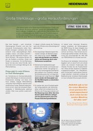
Universally Applicable<br />
– The Right Control for Scores of Applications<br />
The <strong>i<strong>TNC</strong></strong> <strong>530</strong> is versatile. It adapts<br />
optimally to the needs of your company—<br />
regardless of whether you are<br />
manufacturing single parts or batches,<br />
simple or complex parts, whether your<br />
shop works “on call” or is centrally<br />
organized.<br />
Universal milling machine<br />
Shop-fl oor programming in <strong>HEIDENHAIN</strong><br />
conversational format or with smarT.NC<br />
Upwardly compatible programs<br />
Fast presetting with <strong>HEIDENHAIN</strong> 3-D<br />
touch probe<br />
Electronic handwheel<br />
4<br />
The <strong>i<strong>TNC</strong></strong> <strong>530</strong> is fl exible. Do you prefer to<br />
work at the machine or at a programming<br />
station? With the <strong>i<strong>TNC</strong></strong> <strong>530</strong> you can easily<br />
do both, because it is just as powerful in its<br />
shop-fl oor programmability as it is for<br />
offl ine programming:<br />
You can program your own conventional<br />
milling, drilling, and boring operations at<br />
the machine in dialog with the control.<br />
The <strong>i<strong>TNC</strong></strong> <strong>530</strong> gives you optimal support<br />
with smarT.NC or plain language—the<br />
conversational guidance from<br />
High speed milling<br />
Fast block processing<br />
Short control-loop cycle time<br />
Jerk-free path control<br />
High spindle speed<br />
Fast data transfer<br />
<strong>HEIDENHAIN</strong>—as well as with<br />
numerous graphic aids including practiceoriented<br />
fi xed cycles. For simple work—<br />
such as face milling—you need not write a<br />
program, since it is easy to operate the<br />
machine manually with the <strong>i<strong>TNC</strong></strong> <strong>530</strong>.<br />
The <strong>i<strong>TNC</strong></strong> <strong>530</strong> can be programmed<br />
remotely just as well—for example on a<br />
CAM system or at a <strong>HEIDENHAIN</strong><br />
programming station. Your Ethernet<br />
interface guarantees very short transfer<br />
times, even of long programs.<br />
Five-axis machining with swivel head<br />
and rotary table<br />
When you are programming away from<br />
the machine, the <strong>i<strong>TNC</strong></strong> <strong>530</strong> automatically<br />
takes the machine geometry into<br />
account<br />
Tilting the working plane<br />
Cylindrical surface machining<br />
Tool Center Point Management (TCPM)<br />
3-D tool compensation<br />
Fast execution through short block<br />
processing times
The <strong>i<strong>TNC</strong></strong> <strong>530</strong> is universal. Its broad and<br />
complex range of applications proves it.<br />
Whether on simple 3-axis universal milling<br />
machines in tool and mold making,<br />
or on machining centers in interlinked<br />
production—in either case, the <strong>i<strong>TNC</strong></strong> <strong>530</strong> is<br />
the right control. And it offers the applicable<br />
features both necessary and helpful.<br />
Five-axis machining on very large<br />
machines<br />
Inspecting and optimizing machine<br />
accuracy with KinematicsOpt<br />
Global program settings for<br />
superimposition of various functions<br />
Procedure with handwheel<br />
superimposition in the virtual tool axis<br />
Boring mill<br />
Cycles for drilling, boring and spindle<br />
alignment<br />
Drilling oblique holes<br />
Control of quills (parallel axes)<br />
Machining centers and automated<br />
machining<br />
Tool management<br />
Pallet management<br />
Tool-oriented machining<br />
Controlled presetting<br />
Reference-point management with<br />
preset tables<br />
Automatic workpiece measurement with<br />
<strong>HEIDENHAIN</strong> 3-D touch probes<br />
Automatic tool measurement and<br />
breakage inspection<br />
Connection with host computer<br />
5
Well Designed and User Friendly<br />
– The <strong>i<strong>TNC</strong></strong> <strong>530</strong> in Dialog with the User<br />
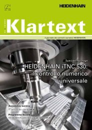
The screen<br />
The large 19-inch TFT color fl at-panel<br />
display shows a clear overview of all<br />
relevant information for programming,<br />
operating and inspecting the machine tool<br />
and control, such as program blocks,<br />
comments and error messages. More<br />
information is provided through graphic<br />
support during program entry, test run and<br />
actual machining.<br />
The selectable “split screen” display<br />
shows the part program blocks in one half<br />
of the screen and the graphics or the<br />
status display in the other half.<br />
During the course of the program, status<br />
displays will always offer information on<br />
tool position, the current program, active<br />
cycles and coordinate transformations, and<br />
other data. The <strong>i<strong>TNC</strong></strong> <strong>530</strong> even shows the<br />
current machining time.<br />
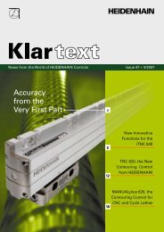
The keyboard<br />
As with all <strong>TNC</strong>s from <strong>HEIDENHAIN</strong>, the<br />
keyboard is tailored to the programming<br />
process. The well-thought-out arrangement<br />
of keys in a clear division into function<br />
groups, i.e. programming modes,<br />
machining modes, management/<strong>TNC</strong><br />
functions and navigation, supports you<br />
during program input. Simple key<br />
assignment, easily understandable<br />
symbols or abbreviations clearly indicate<br />
each key’s function.<br />
The alphabetic keypad enables you to<br />
easily enter comments and G codes. The<br />
integrated machine operating panel<br />
features easily exchangeable snap-on keys<br />
that allow simple adaptation to the<br />
respective machine confi guration. You use<br />
the override potentiometers to make<br />
delicate adjustments of feed-rate, rapid<br />
traverse and spindle speed. And the<br />
operating panel features a complete set of<br />
PC keys and a touchpad that can be used,<br />
for example, for operating the DXF<br />
converter.<br />
6
The screen content includes two<br />
operating modes, the program, graphics<br />
and the machine status<br />
PLC function keys (soft keys) for machine<br />
functions<br />
Keys for screen management (screen<br />
layout), mode of operation and for shifting<br />
between soft-key rows<br />
Self-explanatory function keys (soft keys)<br />
for NC programming<br />
Alphanumeric keyboard for comments or<br />
DIN/ISO programs and a set of PC keys for<br />
controlling the operating system functions.<br />
USB port for additional data storage or<br />
pointing devices<br />
Axis-selection keys and numeric keypad<br />
Override potentiometers for feed rate,<br />
rapid traverse and spindle speed<br />
Function keys for programming modes,<br />
machine modes, <strong>TNC</strong> functions,<br />
management and navigation<br />
Machine operating panel with snap-on<br />
keys and LEDs<br />
Ergonomic and elegant, state-of-the-art<br />
and fi eld-proven—<strong>HEIDENHAIN</strong> controls<br />
in a new design. Judge for yourself:<br />
Durable<br />
The high-quality stainless steel design of<br />
the <strong>i<strong>TNC</strong></strong> <strong>530</strong> features a special protection<br />
coating and is therefore highly resistant to<br />
soiling and wear.<br />
Smooth<br />
The rectangular, slightly rounded keys are<br />
pleasant for your fi ngers and reliable in<br />
operation. Their inscriptions stay free of<br />
wear even under extreme workshop<br />
conditions.<br />
Flexible<br />
The integrated machine operating panel<br />
features easily exchangeable snap-on keys.<br />
Reliable<br />
The elevated key bed of the machine<br />
operating panel prevents accidental<br />
actuation. LEDs serve for status display of<br />
each key by clearly indicating the active<br />
machine functions.<br />
Versatile<br />
Soft keys both for the programming and<br />
the machine functions always show only<br />
the currently available selection.<br />
Sensitive<br />
With the handy control knobs you can<br />
individually adjust the feed-rate, rapid<br />
traverse and spindle speed.<br />
Communicative<br />
The fast USB 2.0 interface lets you connect<br />
storage media or pointing devices to the<br />
keyboard simply and directly.<br />
7
Consistently Upward Compatible<br />
– A Promising Future with <strong>HEIDENHAIN</strong> Contouring Controls<br />
For 30 years, <strong>HEIDENHAIN</strong> has been<br />
supplying contouring controls for milling,<br />
drilling and boring. Of course the controls<br />
have undergone development during this<br />
period: many new features have been<br />
added—also for more complex machines<br />
with more axes. The basic operational<br />
technique, however, has remained the<br />
same. The machinist who has been<br />
working with <strong>TNC</strong> does not have to relearn.<br />
On the <strong>i<strong>TNC</strong></strong> <strong>530</strong> he immediately uses all<br />
of his previous experience with <strong>TNC</strong>s,<br />
programming and working as before.<br />
1997: <strong>TNC</strong> 426 M<br />
<strong>TNC</strong> 430<br />
8<br />
2001: <strong>i<strong>TNC</strong></strong> <strong>530</strong><br />
1993: <strong>TNC</strong> 426 C/P<br />
1988: <strong>TNC</strong> 407<br />
<strong>TNC</strong> 415<br />
2004: <strong>i<strong>TNC</strong></strong> <strong>530</strong><br />
with smarT.NC<br />
2011: <strong>i<strong>TNC</strong></strong> <strong>530</strong><br />
with HSCI<br />
These contouring keys from the <strong>TNC</strong> 145<br />
are also on the <strong>i<strong>TNC</strong></strong> <strong>530</strong><br />
1987: <strong>TNC</strong> 355 1984: <strong>TNC</strong> 155<br />
2012: <strong>i<strong>TNC</strong></strong> <strong>530</strong> in a<br />
new design
2012: <strong>TNC</strong> <strong>640</strong> for<br />
milling/turning<br />
machines<br />
Inside contour—<br />
1983: <strong>TNC</strong> 150<br />
“Old” programs also run on newer <strong>TNC</strong><br />
controls<br />
Part programs from your NC program<br />
archive that were written on older <strong>TNC</strong><br />
contouring controls can also be run on an<br />
<strong>i<strong>TNC</strong></strong> <strong>530</strong> with very little effort. This<br />
ensures the greatest possible fl exibility in<br />
machine utilization and provides enormous<br />
cost benefi ts if you fi nd you have to<br />
produce old parts again. <strong>HEIDENHAIN</strong><br />
contouring controls put you in the position<br />
to manufacture a replacement part quickly<br />
and economically even now—after more<br />
than 30 years—without having to<br />
reprogram it.<br />
programmed with the <strong>TNC</strong> 145...<br />
1981: <strong>TNC</strong> 145,<br />
the fi rst contouring control<br />
from <strong>HEIDENHAIN</strong><br />
...machined with the <strong>i<strong>TNC</strong></strong> <strong>530</strong><br />
Familiar function keys take on new<br />
tasks<br />
Of course, many innovations and<br />
improvements have been included<br />
in the <strong>i<strong>TNC</strong></strong> <strong>530</strong>—but the fundamental<br />
programming procedure has remained the<br />
same. When you switch to a new control<br />
you do not need to relearn the programming<br />
and operation. You only need to become<br />
familiar with the new functions. So you can<br />
apply your professional knowledge as a<br />
machinist immediately even on a new <strong>TNC</strong><br />
control.<br />
9
Machining with Five Axes<br />
– The <strong>i<strong>TNC</strong></strong> <strong>530</strong> Permits Optimum Tool Movement<br />
Modern machines often work with four or<br />
fi ve positioning axes. This makes it possible<br />
to machine complex 3-D contours. The<br />
required programs are usually created on<br />
external CAM systems and comprise a<br />
large number of very short line segments<br />
that are transferred to the control. Whether<br />
the workpiece is actually machined<br />
according the program’s instructions<br />
depends essentially on the geometric<br />
behavior of the control. With its optimized<br />
path control, its precalculation of the<br />
contour and its algorithms for jerk<br />
limitation, the <strong>i<strong>TNC</strong></strong> <strong>530</strong> has the right<br />
functions for a perfect surface in the<br />
shortest possible machining time. See for<br />
yourself. In the end, it’s the quality of the<br />
workpiece that proves the performance of<br />
the control.<br />
10<br />
3-D contour machining at its fi nest<br />
The <strong>i<strong>TNC</strong></strong> <strong>530</strong>’s short block processing<br />
time of only 0.5 ms for a 3-D line segment<br />
without tool compensation permits high<br />
traversing speeds even on complex<br />
contours. This enables you, for example,<br />
to mill molds or dies approximated with<br />
0.2 mm line segments at feed rates as<br />
high as 24 meters per minute.<br />
The particularly jerk-free path control<br />
when machining 3-D fi gures and the<br />
defi ned rounding of series of straight-line<br />
segments provide you with smoother<br />
surfaces as well as high dimensional<br />
accuracy.<br />
The <strong>i<strong>TNC</strong></strong> <strong>530</strong> thinks ahead. Its “lookahead”<br />
function anticipates future changes<br />
in direction by adjusting the traversing<br />
speed to the programmed surface. If<br />
desired, it also enables the <strong>i<strong>TNC</strong></strong> <strong>530</strong> to<br />
reduce the feed rate when plunging the<br />
tool into the workpiece. This lets you<br />
simply program the maximum machining<br />
speed as the feed rate. The <strong>i<strong>TNC</strong></strong> <strong>530</strong><br />
automatically adapts the actual speed of<br />
the workpiece contour to save you<br />
machining time.<br />
For NC programs with normal vectors,<br />
such as those generated by CAM systems,<br />
the <strong>i<strong>TNC</strong></strong> <strong>530</strong> automatically calculates a 3-D<br />
tool compensation for end mills, ball-nose<br />
cutters, or toroid cutters.
– Compensating Form Errors of Tools with 3D-ToolComp (Option)<br />
3D-ToolComp is a new and powerful<br />
option for three-dimensional tool radius<br />
compensation. A compensation-value table<br />
is used to defi ne angle-dependent delta<br />
values that describe the tool deviation from<br />
the ideal circular shape (see fi gure).<br />
The <strong>i<strong>TNC</strong></strong> then corrects the radius value<br />
defi ned for the tool’s current point of<br />
contact with the workpiece. In order to<br />
determine the point of contact exactly, the<br />
NC program must be have been created<br />
with surface-normal blocks (LN blocks) by<br />
a CAM system. The surface-normal blocks<br />
specify the theoretical center point of the<br />
radius cutter, and in some cases also the<br />
tool orientation relative to the workpiece<br />
surface.<br />
Ideally, the compensation-value table is<br />
generated fully automatically by way of a<br />
special cycle that uses a laser system to<br />
measure the form of the tool so that the<br />
<strong>i<strong>TNC</strong></strong> can use this table directly. If the form<br />
deviations of the tool used are available<br />
as a calibration chart from the tool<br />
manufacturer, then you can create the<br />
compensation-value table manually.<br />
Z<br />
<strong>DR</strong>2–0.004<br />
<strong>DR</strong>2+0.002<br />
X<br />
11
Machining with Five Axes<br />
– Guided Tool Tip<br />
CAM systems use postprocessors to<br />
generate fi ve-axis programs. In principle,<br />
such programs contain either all coordinates<br />
of the machine’s existing NC axes, or NC<br />
blocks with surface normal vectors. When<br />
machining with fi ve axes (three linear axes<br />
and two tilting axes*), the tool can stay<br />
perpendicular, or if desired, inclined at a<br />
predetermined angle to the workpiece<br />
surface.<br />
12<br />
Regardless of what type of 5-axis<br />
programs you wish to run, the <strong>i<strong>TNC</strong></strong> <strong>530</strong><br />
makes all the compensating movements in<br />
the linear axes that result from movements<br />
in the tilting axes. The <strong>i<strong>TNC</strong></strong> <strong>530</strong>’s Tool<br />
Center Point Management feature<br />
(TCPM)—an improvement upon the proven<br />
<strong>TNC</strong> function M128—provides optimal tool<br />
guidance and prevents contour gouging.<br />
* The machine and the <strong>i<strong>TNC</strong></strong> must be adapted to these<br />
functions by the machine tool builder.
With TCPM you can defi ne the behavior of<br />
the tilting and compensating movements<br />
automatically calculated by the <strong>i<strong>TNC</strong></strong> <strong>530</strong>.<br />
TCPM defi nes the interpolation between<br />
the start and end positions:<br />
During face milling—machining mainly<br />
with the face of the tool—the tool point<br />
moves on a straight line. The path of the<br />
tool’s cylindrical surface is not defi ned,<br />
but rather it depends on the machine<br />
geometry.<br />
During peripheral milling, machining is<br />
mainly by the side of the tool. The tool tip<br />
also travels on a straight path, but<br />
additionally the tool’s circumference<br />
machines an explicitly defi ned plane.<br />
TCPM defi nes the effect of the<br />
programmed feed rate as desired either<br />
as the actual velocity of the tool tip<br />
relative to the workpiece. Very high<br />
axis feed rates can result from large<br />
compensating motions during machining<br />
near the center of tilting.<br />
as contouring feed rate of the axes<br />
programmed in the NC block. The feed<br />
rate is usually lower, but you attain better<br />
surface quality during large compensating<br />
movements.<br />
With TCPM you can also defi ne the effect<br />
of the inclination angle for more uniform<br />
cutting passes when working with an<br />
inclined radius cutter:<br />
Angle of inclination defi ned as axis angle<br />
Angle of inclination defi ned as spatial<br />
angle<br />
The <strong>i<strong>TNC</strong></strong> takes the inclination angle into<br />
account in all 3-D machining—even with<br />
45° swivel heads or tilting tables. You either<br />
specify the angle of inclination in the NC<br />
program via a miscellaneous function, or<br />
adjust it manually with an electronic<br />
handwheel. The <strong>i<strong>TNC</strong></strong> <strong>530</strong> makes sure that<br />
the tool remains on the contour and does<br />
not damage the workpiece.<br />
13
Machining with Five Axes<br />
– Swivel Head and Rotary Table Controlled by <strong>i<strong>TNC</strong></strong><br />
Many fi ve-axis operations that at fi rst<br />
glance may seem very complex can be<br />
reduced to conventional 2-D movements<br />
that are simply tilted about one or more<br />
rotary axes or wrapped onto a cylindrical<br />
surface. The <strong>i<strong>TNC</strong></strong> supports you with<br />
application-oriented functions to help you<br />
write and edit such programs quickly and<br />
simply without a CAM system.<br />
14<br />
Tilting the working plane*<br />
Programs for contours and holes on<br />
inclined surfaces are often very complex<br />
and require time-consuming computing<br />
and programming work. Here the <strong>i<strong>TNC</strong></strong> <strong>530</strong><br />
helps you to save a great deal of<br />
programming time.<br />
You program the part as usual in the<br />
working plane (e.g. the X/Y plane), but it is<br />
machined in a plane that is rotated in one<br />
or more axes about the main plane.<br />
The PLANE feature makes it easy to defi ne<br />
a tilted working plane: You can specify tilted<br />
working planes in seven different ways,<br />
depending on the information on the<br />
workpiece drawing. In order to keep the<br />
use of these complex functions as simple<br />
as possible, a separate animation is<br />
available for each possible plane defi nition,<br />
so that you can view them before selecting<br />
the function. Clearly arranged support<br />
graphics assist you during input.<br />
You can defi ne the positioning behavior<br />
with the PLANE function so that there are<br />
no unpleasant surprises when the program<br />
is run. The settings for defi ning the<br />
positioning behavior are identical for all<br />
PLANE functions, making everything that<br />
much easier.<br />
* The machine and the <strong>i<strong>TNC</strong></strong> must be adapted to these<br />
functions by the machine tool builder.
Machining cylindrical surfaces*<br />
With the <strong>i<strong>TNC</strong></strong> <strong>530</strong> it is quite easy to<br />
program contours (which consist of straight<br />
lines and arcs) on cylindrical surfaces using<br />
rotary and tilting tables: You simply program<br />
the contour in a plane as if the cylinder<br />
surface were unrolled. The <strong>i<strong>TNC</strong></strong> <strong>530</strong> then<br />
executes the operation on the surface of<br />
the cylinder.<br />
The <strong>i<strong>TNC</strong></strong> <strong>530</strong> features four cycles for<br />
cylindrical surface machining:<br />
Slot milling (the slot width is the same as<br />
the tool diameter)<br />
Guide-groove milling (the slot width is<br />
greater than the tool diameter)<br />
Ridge milling<br />
Mill outside of contour<br />
* The machine and the <strong>i<strong>TNC</strong></strong> must be adapted to these<br />
functions by the machine tool builder.<br />
Manual axis motion in the tool direction<br />
on 5-axis machines<br />
The safe retraction of a tool is very<br />
important with fi ve-axis machining. The<br />
“virtual tool axis” function is of assistance<br />
here. You can use it to traverse the tool in<br />
the current direction of the tool axis<br />
through an external direction key or the<br />
handwheel. This function is especially<br />
useful if you want to<br />
retract the tool in the direction of the tool<br />
axis during interruption of a fi ve-axis<br />
machining program, or<br />
use the handwheel or external direction<br />
keys to perform an operation in Manual<br />
mode and the tool is in contact.<br />
move the tool with the handwheel in the<br />
active tool axis direction during<br />
machining.<br />
Linear feed rate for rotary tables<br />
in mm/min*<br />
In the standard version, the feed rate of<br />
rotary axes is programmed in degrees/<br />
minute. However, the <strong>i<strong>TNC</strong></strong> <strong>530</strong> can<br />
interpret this feed rate in mm/min as well.<br />
The feed rate at the contour is then<br />
independent of the distance of the tool<br />
center from the center of the rotary axis.<br />
15
Intelligent Machining<br />
– Dynamic Collision Monitoring Option (DCM)<br />
The complex motions and high traversing<br />
speeds of fi ve-axis machining make axis<br />
movements diffi cult to foresee. This makes<br />
collision monitoring a valuable function that<br />
relieves the machine operator and protects<br />
the machine from damage.<br />
NC programs from CAM systems may<br />
avoid collisions of the tool or tool holder<br />
with the workpiece, but unless you invest<br />
in expensive offl ine machine simulation<br />
software, they ignore the machine<br />
components located within the work<br />
envelope. And even then it cannot be<br />
guaranteed that machine conditions, such<br />
16<br />
as the fi xture position, will be identical to<br />
those of the simulation. In the worst case,<br />
a collision will remain undetected until the<br />
damage is done.<br />
In cases such as these, the machine<br />
operator is supported by the dynamic<br />
collision monitoring (DCM)* feature of<br />
the <strong>i<strong>TNC</strong></strong> <strong>530</strong>. The control interrupts<br />
machining whenever a collision is<br />
imminent, thereby increasing the safety for<br />
the machine and its operator. This helps to<br />
prevent machine damage, which can result<br />
in costly downtimes. Unattended shifts<br />
become safer and more reliable.<br />
However, DCM works not only in<br />
automatic mode. It is also active in<br />
manual operation. If, for example, during<br />
setup the machine operator takes a<br />
collision course to a component or fi xture<br />
in the working space, the <strong>i<strong>TNC</strong></strong> <strong>530</strong> detects<br />
it, stops axis movement, and issues an<br />
error message.<br />
Before actually machining a part, you can<br />
also check for collisions in the Test Run<br />
mode, with a real datum and real tools.<br />
* The machine and the <strong>i<strong>TNC</strong></strong> must be adapted to these<br />
functions by the machine tool builder.
Of course the <strong>i<strong>TNC</strong></strong> <strong>530</strong> also shows the<br />
machine operator—both with an error<br />
message and graphically—which machine<br />
components are endangered. If a collision<br />
warning is displayed, the <strong>TNC</strong> permits<br />
retracting the tool only in those directions<br />
which increase the clearance between the<br />
colliding objects.<br />
The machine tool builder takes care<br />
of the required defi nition of machine<br />
components. The working space and<br />
the collision objects are described using<br />
geometric bodies such as planes, cubes<br />
and cylinders. Complex machine<br />
components can be modeled with multiple<br />
geometric bodies. The tool is automatically<br />
considered a cylinder of the tool radius<br />
(defi ned in the tool table). For tilting<br />
devices, the machine tool builder can use<br />
the tables for the machine kinematics also<br />
to defi ne the collision objects.<br />
The last step of the confi guration process<br />
is defi ning which machine components can<br />
collide. Because the machine design in<br />
itself prevents collisions between certain<br />
machine components, they can be ruled<br />
out from the start. For example, a tool<br />
touch probe like the <strong>HEIDENHAIN</strong> TT<br />
clamped on the machine table can never<br />
come into contact with the machine cabin.<br />
When using the dynamic collision<br />
monitoring, please note:<br />
While DCM can help reduce the danger<br />
of collision, it cannot eliminate it.<br />
Only the machine manufacturer can<br />
defi ne machine components. The<br />
operator creates fi xtures from fi xture<br />
templates, which are provided by<br />
<strong>HEIDENHAIN</strong> or by the machine<br />
manufacturer.<br />
Collisions between machine<br />
components (such as swivel heads) and<br />
the workpiece cannot be detected.<br />
DCM cannot be used during operation in<br />
following error mode (which means<br />
without feedforward).<br />
In the Test Run operating mode you can<br />
check for collision before actually<br />
machining the workpiece.<br />
17
Intelligent Machining<br />
– Option for Adaptive Feed Rate Control (AFC)<br />
Besides the feed rate for each block or<br />
cycle, <strong>HEIDENHAIN</strong> controls have always<br />
allowed the programmer to enter a manual<br />
compensation through the override<br />
potentiometer to adjust for the actual<br />
machining situation. But this always<br />
depends on the experience and, of<br />
course, the presence of the operator.<br />
Adaptive feed rate control (AFC)<br />
automatically regulates the feed rate<br />
of the <strong>TNC</strong>, taking into consideration<br />
the respective spindle power and other<br />
process data. In a teach-in cut, the <strong>i<strong>TNC</strong></strong><br />
records the maximum spindle power. Then,<br />
before actual machining, you defi ne in a<br />
table the respective limit values between<br />
which the <strong>i<strong>TNC</strong></strong> can infl uence the feed rate<br />
18<br />
in the adaptive control mode in the<br />
“control” mode. Of course, various<br />
overload reactions can be provided for,<br />
which can also be defi ned by your machine<br />
tool builder.<br />
Adaptive feed rate control offers various<br />
advantages:<br />
Optimizing the machining time<br />
Fluctuations in dimensions or material<br />
(blowholes) often appear particularly on<br />
cast parts. With a corresponding adaptation<br />
of the feed rate, the control tries to keep<br />
the previously "learned" maximum spindle<br />
power during the entire machining time.<br />
The total machining time is shortened by<br />
an increased feed rate in the machining<br />
zones with less stock removal.<br />
Tool monitoring<br />
The <strong>i<strong>TNC</strong></strong>'s adaptive feed rate control<br />
permanently compares the spindle power<br />
with the feed rate. As a tool becomes<br />
blunt, the spindle power increases. As a<br />
result, the <strong>i<strong>TNC</strong></strong> reduces the feed rate. As<br />
soon as the feed rate falls below a defi ned<br />
minimum, the <strong>i<strong>TNC</strong></strong> reacts with an error<br />
message or by switching off. This helps to<br />
prevent further damage after a tool breaks<br />
or is worn out.<br />
Protection of the machine mechanics<br />
Reducing the feed rate down to the<br />
reference value whenever the learned<br />
maximum permissible spindle power is<br />
exceeded also reduces the strain and wear<br />
on the machine. It effectively protects the<br />
spindle from overload.
– Global Settings (Options)<br />
The global program settings, which come<br />
into play particularly in large-scale mold<br />
making, are available in the Program Run<br />
and MDI modes. It allows you to defi ne<br />
various coordinate transformations and<br />
settings with global and priority effect for<br />
the selected NC program, without having<br />
to edit it.<br />
You can change the global program settings<br />
during a program stop even in mid-program.<br />
A clearly structured form is provided for<br />
this. After program start the <strong>i<strong>TNC</strong></strong> then<br />
moves, if necessary, to a new position with<br />
a positioning logic infl uenced by you.<br />
The following functions are available:<br />
Exchanging axes<br />
Additional, additive datum shift<br />
Superimposed mirroring<br />
Axis locking<br />
Handwheel superimposition, with axisspecifi<br />
c memory of paths covered per<br />
handwheel, also in virtual axis direction<br />
Superimposed basic rotation<br />
Superimposed rotation<br />
Globally valid feed-rate factor<br />
19
Intelligent Machining<br />
– Machining Any Contour Slots with Trochoidal Milling<br />
The benefi t of trochoidal milling is its<br />
ultraeffi cient machining of slots of all kinds.<br />
The roughing process is with circular<br />
motion superimposed on a forward linear<br />
motion. This procedure is referred to as<br />
trochoidal milling. It is used particularly for<br />
milling high-strength or hardened materials,<br />
where the high loads placed on the tool<br />
and machine usually only permit small<br />
infeeds.<br />
20<br />
With trochoidal milling, on the other hand,<br />
large cutting depths and high cutting<br />
speeds are possible, since the prevailing<br />
cutting conditions do not increase the wear<br />
and tear on the tool. On the contrary, the<br />
entire length of the cutting edge of<br />
indexable inserts can be used. This enables<br />
you to achieve a greater chip volume per<br />
tooth. Circular plunging into the material<br />
places less radial force on the tool. This<br />
reduces the mechanical load on the<br />
machine and prevents vibration. Enormous<br />
amounts of time can be saved by<br />
combining this milling method with the<br />
integrated adaptive feed control (AFC)<br />
option.<br />
The slot to be machined is described in a<br />
contour subprogram as a contour train. You<br />
defi ne the dimensions of the slot and the<br />
cutting data in a separate cycle. Any residual<br />
material remaining can then easily be<br />
removed with a subsequent fi nishing cut.<br />
The benefi ts include:<br />
The entire length of the cutter is<br />
engaged<br />
Higher cutting values<br />
Higher chip volume<br />
Relieves mechanical load on the machine<br />
Less vibration<br />
Integrated fi nishing of the side wall
Higher Speed, More Accuracy, Truer Contours<br />
– High Speed Milling with the <strong>i<strong>TNC</strong></strong> <strong>530</strong><br />
High speed cutting<br />
High Speed Cutting stands for quick and<br />
effi cient contour milling. The control must<br />
be able to transfer large amounts of data<br />
quickly, make long programs effi cient to<br />
edit, and produce the desired ideal contour<br />
on the workpiece. All qualities that the<br />
<strong>i<strong>TNC</strong></strong> <strong>530</strong> possesses.<br />
Very short block processing times<br />
Block processing speeds are progressively<br />
being pushed into the background by<br />
sophisticated feedforward servo methods.<br />
Nevertheless, short block processing times<br />
remain the best solution for certain<br />
machining tasks. One example is the<br />
machining of highly accurate contours with<br />
very high resolution. This is no problem for<br />
the <strong>i<strong>TNC</strong></strong> <strong>530</strong>. Here the control provides<br />
ideal performance with block processing<br />
times of less than one millisecond.<br />
Very high contour accuracy<br />
The <strong>i<strong>TNC</strong></strong> <strong>530</strong> calculates the contour for up<br />
to 1024 blocks in advance. This enables it<br />
to adapt the axis velocities to the contour<br />
transitions. It controls the axes with special<br />
algorithms that ensure path control with<br />
the required limits to velocity and<br />
acceleration. The integrated fi lters<br />
specifi cally suppress machine-specifi c<br />
natural vibration. Of course, the desired<br />
accuracy of the surface is maintained.<br />
Spline interpolation<br />
If your CAM system describes contours as<br />
splines, you can transfer them directly to<br />
the control. The <strong>i<strong>TNC</strong></strong> <strong>530</strong> features a spline<br />
interpolator and can process third-degree<br />
polynomials.<br />
Fast machining at specifi ed accuracy<br />
You as user specify the accuracy of the<br />
machine contour—apart from the NC<br />
program. You simply enter in the control<br />
through a cycle the maximum permissible<br />
deviations from the ideal contour. The<br />
<strong>i<strong>TNC</strong></strong> <strong>530</strong> automatically adapts the<br />
machining to the tolerance that you defi ne.<br />
No contour damage occurs with this<br />
method.<br />
Digital drive technology<br />
The position controller, speed controller<br />
and, if required, the current controller are<br />
integrated in the <strong>i<strong>TNC</strong></strong> <strong>530</strong>. The digital<br />
motor control makes it possible to attain<br />
very high feed rates. Of course, the<br />
<strong>i<strong>TNC</strong></strong> <strong>530</strong> can interpolate simultaneously in<br />
up to fi ve axes. To reach the required<br />
cutting speed, the <strong>i<strong>TNC</strong></strong> <strong>530</strong> digitally<br />
controls spindle speeds up to 60 000 rpm.<br />
21
Automated Machining<br />
– The <strong>i<strong>TNC</strong></strong> <strong>530</strong> Manages, Measures and Communicates<br />
The difference in requirements placed on<br />
the classical machine for tool and moldmaking<br />
and machining centers are<br />
becoming ever less distinct. Today of<br />
course the <strong>i<strong>TNC</strong></strong> <strong>530</strong> is particularly capable<br />
of controlling automated processes. It<br />
masters the range of functions needed to<br />
start the proper machining operations on<br />
individual workpieces in any setup and<br />
even in interlinked machining.<br />
22<br />
Tool management<br />
For machining centers with automatic tool<br />
changers, the <strong>i<strong>TNC</strong></strong> <strong>530</strong> offers a central tool<br />
memory for up to 32 767 tools. The tool<br />
memory is a freely confi gurable fi le and<br />
can therefore be optimally fi tted to your<br />
needs. You can even have the <strong>i<strong>TNC</strong></strong> <strong>530</strong><br />
manage your tool names. The control<br />
prepares the next tool change while the<br />
current tool is still cutting. This signifi cantly<br />
reduces the non-cutting time required for<br />
changing tools.<br />
With the optionally available expanded tool<br />
management you can also graphically<br />
prepare and display any data.*<br />
* The machine and the <strong>i<strong>TNC</strong></strong> must be adapted to these<br />
functions by the machine tool builder.<br />
Pallet management<br />
The <strong>i<strong>TNC</strong></strong> <strong>530</strong> can assign the appropriate<br />
part program and datum shift to parts<br />
mounted on pallets and brought to the<br />
machine in any sequence. If a pallet is<br />
exchanged, the <strong>i<strong>TNC</strong></strong> <strong>530</strong> automatically<br />
calls the correct part program. This permits<br />
automatic machining of a variety of parts in<br />
any sequence.
Tool-oriented machining<br />
In tool-oriented machining, one machining<br />
step is performed on all workpieces on a<br />
pallet before the next machining step. This<br />
reduces the number of tool changes to a<br />
necessary minimum and the machining<br />
time is signifi cantly shorter.<br />
The <strong>i<strong>TNC</strong></strong> <strong>530</strong> supports you with<br />
convenient input forms with which you can<br />
assign a tool-oriented machining operation<br />
to a pallet with several workpieces on<br />
several fi xtures. You can write the program,<br />
however, in the familiar workpiece-oriented<br />
sequence.<br />
You can also use this function even if your<br />
machine does not support pallet<br />
management. In the pallet fi le you then<br />
simply defi ne the positions of the<br />
workpieces on your machining table.<br />
Inspecting workpieces for proper<br />
machining and dimensional accuracy<br />
The <strong>i<strong>TNC</strong></strong> <strong>530</strong> features a number of<br />
measuring cycles for checking the<br />
geometry of the machined workpieces.<br />
To run the measuring cycles, you insert a<br />
3-D touch probe from <strong>HEIDENHAIN</strong> (see<br />
page 42) into the spindle in place of a tool<br />
for the following tasks:<br />
Recognize a workpiece and call the<br />
appropriate part program<br />
Check whether all machining operations<br />
were conducted correctly<br />
Determine infeeds for fi nishing<br />
Detect and compensate tool wear<br />
Check workpiece geometry and sort<br />
parts<br />
Log measured data<br />
Ascertain machining error trends<br />
Workpiece measurement and automatic<br />
compensation of tool data<br />
Together with the TT 140, TL Nano and<br />
TL Micro systems for tool measurement<br />
(see page 43), the <strong>i<strong>TNC</strong></strong> <strong>530</strong> can<br />
automatically measure tools while they are<br />
in the machine. The <strong>i<strong>TNC</strong></strong> <strong>530</strong> saves the<br />
ascertained values of tool length and radius<br />
in the central tool fi le. By inspecting the<br />
tool during machining you can quickly and<br />
directly measure wear or breakage to<br />
prevent scrap or rework. If the measured<br />
deviations lie outside the tolerances, or if<br />
the monitored life of the tool is exceeded,<br />
the <strong>i<strong>TNC</strong></strong> <strong>530</strong> locks the tool and<br />
automatically inserts a replacement tool.<br />
23
Minimize Setup Times<br />
– The <strong>i<strong>TNC</strong></strong> <strong>530</strong> Makes Setup Easy<br />
Before you can begin machining, you must<br />
fi rst clamp the tool and set up the machine,<br />
fi nd the position and orientation of the<br />
workpiece on the machine, and set the<br />
workpiece reference point. This is a timeconsuming<br />
but indispensable procedure.<br />
After all, any error directly reduces the<br />
machining accuracy. Particularly in small<br />
and medium-sized production runs, as well<br />
as for very large workpieces, setup times<br />
become quite a signifi cant factor.<br />
The <strong>i<strong>TNC</strong></strong> <strong>530</strong> features application-oriented,<br />
real-world setup functions. They support<br />
the user, help to reduce non-productive<br />
time, and make overnight, unattended<br />
production possible. Together with the<br />
3-D touch probes, the <strong>i<strong>TNC</strong></strong> <strong>530</strong> offers<br />
numerous probing cycles for automatic<br />
alignment of the workpieces, presetting,<br />
and measurement of the workpiece and<br />
the tool.<br />
24<br />
Delicate manual traverse<br />
For setup, you can use the direction keys<br />
to move the machine axes manually or in<br />
incremental jog. A simpler and more<br />
reliable way, however, is to use the<br />
electronic handwheels from <strong>HEIDENHAIN</strong><br />
(see page 45). Particularly with the portable<br />
handwheels you are always close to the<br />
action, enjoy a close-up view of the setup<br />
process, and can control the infeed<br />
responsively and precisely.<br />
Workpiece alignment<br />
With the 3-D touch probes from<br />
<strong>HEIDENHAIN</strong> (see page 42) and the<br />
probing functions of the <strong>i<strong>TNC</strong></strong> <strong>530</strong>, you<br />
can forgo any tedious manual alignment<br />
of the workpiece:<br />
Clamp the workpiece in any position.<br />
The touch probe ascertains the<br />
workpiece misalignment by probing a<br />
surface, two holes, or two studs.<br />
The <strong>i<strong>TNC</strong></strong> <strong>530</strong> compensates the<br />
misalignment with a “basic rotation,”<br />
which means that in the NC program the<br />
part is rotated by the measured<br />
misalignment.<br />
Compensating workpiece misalignment<br />
Compensate misalignment by rotating the<br />
coordinate system or turning the table
Workpiece presetting<br />
You can use a reference point to assign a<br />
defi ned value in the <strong>i<strong>TNC</strong></strong> display to any<br />
workpiece position. Finding this point<br />
quickly and reliably reduces nonproductive<br />
time and increases machining accuracy.<br />
The <strong>i<strong>TNC</strong></strong> <strong>530</strong> features probing cycles for<br />
automatic presetting. Once found, you can<br />
save reference points<br />
in the workpiece preset table,<br />
in a workpiece datum table, or<br />
by directly setting the displayed value.<br />
Workpiece presetting<br />
At a corner, for example, or in the center of<br />
a bolt hole circle<br />
Preset table: The <strong>i<strong>TNC</strong></strong>’s central reference<br />
point management<br />
The preset table makes fl exible machining,<br />
shorter setup times and increased<br />
productivity possible. In other words,<br />
it makes it much easier to set up the<br />
machine.<br />
In the preset table you can save any<br />
number of reference points and assign an<br />
individual basic rotation to each one.<br />
When working in a tilted plane and<br />
presetting a reference point, the <strong>i<strong>TNC</strong></strong><br />
includes the respective positions of the<br />
rotary axes. In this way, the reference point<br />
also remains active in any other angular<br />
position.<br />
On machines with an automatic spindle<br />
head changer, the reference point remains<br />
unchanged after a head exchange, even if<br />
they differ kinematically (i.e. in their<br />
dimensions).<br />
The <strong>i<strong>TNC</strong></strong> automatically creates separate<br />
preset tables for individual traverse ranges<br />
(such as for alternating table machining).<br />
When changing traverse ranges, the <strong>i<strong>TNC</strong></strong><br />
activates the correct preset table with the<br />
most recently active reference point.<br />
There are three ways to save reference<br />
points in the preset table:<br />
In the Manual mode by soft key<br />
By using the probing functions<br />
With the automatic probing cycles<br />
25
Programming, Editing, Testing<br />
– The <strong>i<strong>TNC</strong></strong> <strong>530</strong> Opens Endless Possibilities<br />
The <strong>i<strong>TNC</strong></strong> <strong>530</strong> is just as universal in<br />
application as it is fl exible in machining<br />
and programming.<br />
Programming at the machine<br />
<strong>HEIDENHAIN</strong> controls are workshop<br />
oriented, which means that they were<br />
conceived for programming right at the<br />
machine. The <strong>i<strong>TNC</strong></strong> <strong>530</strong> supports you with<br />
two user interfaces:<br />
For 30 years, <strong>HEIDENHAIN</strong> conversational<br />
programming has been the standard<br />
programming language for all <strong>TNC</strong> controls<br />
and for shop-fl oor programming in general.<br />
The new smarT.NC intuitive and selfexplanatory<br />
operating mode uses<br />
straightforward input forms to guide you<br />
through the complete NC programming<br />
process all the way to the actual machining.<br />
There’s no need to learn G functions or any<br />
special programming languages. The<br />
control “speaks” with you using easily<br />
understandable questions and prompts.<br />
Whether plain-language prompts, dialog<br />
guidance, programming steps or soft keys,<br />
all texts are available in numerous<br />
languages.<br />
If you are used to DIN/ISO programming,<br />
however, the <strong>i<strong>TNC</strong></strong> is still the right control—<br />
you can enter DIN/ISO programs over the<br />
alphanumeric keyboard. The most<br />
frequently needed letters are already<br />
highlighted in color.<br />
Positioning with manual data input<br />
You can start working with the <strong>i<strong>TNC</strong></strong> <strong>530</strong><br />
even before writing a complete part<br />
program. Simply machine a part step by<br />
step—switching as you want between<br />
manual operation and automatic<br />
positioning.<br />
Creating programs offl ine<br />
The <strong>i<strong>TNC</strong></strong> <strong>530</strong> is also well equipped for<br />
offl ine programming. The <strong>i<strong>TNC</strong></strong> <strong>530</strong> can<br />
be integrated through its interfaces into<br />
networks and connected with programming<br />
stations, CAD/CAM systems or other data<br />
storage devices.<br />
26
– Fast Availability of All Information<br />
Do you have questions on a programming<br />
step, but your User’s Manual is not at hand?<br />
No problem: The <strong>i<strong>TNC</strong></strong> <strong>530</strong> numerical<br />
control and <strong>i<strong>TNC</strong></strong> <strong>530</strong> programming station<br />
now feature <strong>TNC</strong>guide, a convenient help<br />
system that can show the user<br />
documentation in a separate window.<br />
You can activate <strong>TNC</strong>guide by simply<br />
pressing the help key on the <strong>i<strong>TNC</strong></strong> keyboard<br />
or by clicking any soft key with a cursor in<br />
the shape of a question mark. You switch<br />
the cursor by simply clicking the help<br />
symbol ( ) that appears on all <strong>TNC</strong><br />
screens.<br />
<strong>TNC</strong>guide usually displays the information<br />
in the immediate context of the element in<br />
question (context-sensitive help). This<br />
means that you immediately receive the<br />
relevant information, which is especially<br />
useful when programming a function. This<br />
function is particularly helpful with the soft<br />
keys. The method and effect of operation is<br />
explained in detail.<br />
The <strong>i<strong>TNC</strong></strong> <strong>530</strong> is shipped with integrated<br />
documentation for the respective NC<br />
software in English and German. Other<br />
languages are available for download free<br />
of charge as soon as the translations<br />
become available. After download, you can<br />
save the national language fi les in the<br />
corresponding language directory on the<br />
<strong>TNC</strong>’s hard disk.<br />
The following User’s Manuals are available<br />
in the help system:<br />
Conversational programming<br />
smarT.NC (Pilot format)<br />
Cycle programming<br />
DIN/ISO programming<br />
<strong>i<strong>TNC</strong></strong> <strong>530</strong> programming station (included<br />
only in the programming station)<br />
Also, the <strong>i<strong>TNC</strong></strong> can display standard<br />
formats (PDF, BMP, GIF, JPG etc.).<br />
<strong>TNC</strong>guide<br />
integrated in the<br />
control, e.g. on the<br />
<strong>i<strong>TNC</strong></strong> <strong>530</strong> ...<br />
… or at the<br />
programming<br />
station<br />
27
Programming, Editing, Testing<br />
– Graphic Support in Any Situation<br />
Interactive programming graphics<br />
The two-dimensional programming graphics<br />
give you additional security: while you are<br />
programming, the <strong>i<strong>TNC</strong></strong> <strong>530</strong> draws every<br />
entered traverse command on the screen.<br />
3-D line graphics<br />
The 3-D line graphics display the<br />
programmed tool center point path in three<br />
dimensions. With the powerful zoom<br />
function you can also see the fi nest details.<br />
You should especially use the 3-D line<br />
graphics to inspect programs created<br />
offl ine for irregularities before machining, in<br />
order to avoid undesirable traces of the<br />
machining process on the workpiece, e.g.<br />
when points are output incorrectly by the<br />
postprocessor. In order to fi nd the error<br />
location quickly, the currently active block<br />
of the 3-D line graphics appears highlighted<br />
in the left window. In addition, the<br />
respective programmed end points can be<br />
displayed to show any concentrations of<br />
points.<br />
Help graphics<br />
During cycle programming in the plainlanguage<br />
dialog, the <strong>i<strong>TNC</strong></strong> shows a<br />
separate illustration for each parameter.<br />
This makes it easier to understand the<br />
function and accelerates programming. In<br />
smarT.NC you will fi nd help graphics for all<br />
required input.<br />
28
Test run graphics<br />
To play it safe before running a program,<br />
the <strong>i<strong>TNC</strong></strong> <strong>530</strong> can graphically simulate the<br />
machining of the workpiece. It can display<br />
the simulation in various ways:<br />
In a plan view with different shades of<br />
depth<br />
In three planes (as in the workpiece<br />
drawing)<br />
In a solid model, 3-D view<br />
Details can be displayed in magnifi cation.<br />
The high resolution of the 3-D view<br />
visualizes even very fi ne contours true to<br />
detail and enables you to see even hidden<br />
details clearly and reliably. A simulated light<br />
source provides realistic light-and-shadow<br />
conditions.<br />
When testing complex fi ve-axis programs,<br />
even operations with tilted planes or<br />
multiside machining can be displayed.<br />
In addition, the <strong>i<strong>TNC</strong></strong> <strong>530</strong> indicates the<br />
calculated machining time in hours,<br />
minutes and seconds.<br />
Program-run graphics<br />
On the <strong>i<strong>TNC</strong></strong> <strong>530</strong>, you can run the<br />
programming graphics or verifi cation<br />
graphics even while the workpiece is being<br />
machined. Also, it shows a real-time<br />
graphic of the machining progress during<br />
program run. Coolant spray and protective<br />
enclosures usually obstruct any direct view<br />
of the actual workpiece. You can get around<br />
this with a simple keystroke to see the<br />
simulated progress of workpiece<br />
machining.<br />
29
Programming in the Workshop<br />
– Straightforward Function Keys for Complex Contours<br />
Programming 2-D Contours<br />
Two-dimensional contours are the bread<br />
and butter of the modern machine shop.<br />
Here the <strong>i<strong>TNC</strong></strong> <strong>530</strong> offers a variety of<br />
possibilities.<br />
Programming with path function keys<br />
If contours are dimensioned for NC, which<br />
means that the end points are specifi ed in<br />
Cartesian or polar coordinates, then you<br />
can program them directly with the path<br />
function keys.<br />
30<br />
Straight and circular contour elements<br />
To program a line segment, for example,<br />
simply press the key for linear traverse. The<br />
<strong>i<strong>TNC</strong></strong> <strong>530</strong> asks for all information required<br />
for a complete programming block, such as<br />
target coordinates, feed rate, cutter radius<br />
compensation and machine functions.<br />
Appropriate path function keys for circular<br />
movement, chamfers, and corner rounding<br />
simplify your programming. To avoid<br />
surface blemishes during approach or<br />
departure from the contour, it must be<br />
approached smoothly—that is, tangentially.<br />
CT<br />
Circular path defi ned<br />
by its end point, with<br />
a smooth (tangential)<br />
departure from the<br />
previous contour<br />
element<br />
CC<br />
CR<br />
C<br />
Circular path defi ned<br />
by its center point,<br />
end point, and<br />
rotational direction<br />
Circular path defi ned<br />
by its radius, end point<br />
and rotational<br />
direction<br />
You simply specify the starting or end point<br />
of the contour and the approaching or<br />
departing radius of the cutter edge—the<br />
control does the rest for you.<br />
The <strong>i<strong>TNC</strong></strong> <strong>530</strong> can look ahead over a radiuscompensated<br />
contour for up to 99 blocks<br />
to watch for back cutting and avoid contour<br />
damage such as can occur when roughing<br />
a contour with a large tool.<br />
Straight line defi ned<br />
by its end point<br />
RND Rounding:<br />
circular path<br />
defi ned by radius and<br />
corner point, with a<br />
smooth (tangential)<br />
transition to its adjoining<br />
contour elements<br />
CHF Chamfer:<br />
defi ned by the<br />
corner point and the<br />
chamfer length
– Programming Contours Unconventionally<br />
FK free contour programming<br />
Not all workpieces are dimensioned for<br />
conventional NC programming. Thanks to<br />
FK, the <strong>i<strong>TNC</strong></strong>’s free contour programming<br />
feature, in such cases you simply type in<br />
the known data—without fi rst having to<br />
convert or calculate your data! It does not<br />
matter if individual contour elements are<br />
not completely defi ned as long as the<br />
complete contour has been. If the given<br />
data result in more than one mathematical<br />
solution, the helpful <strong>i<strong>TNC</strong></strong> <strong>530</strong> programming<br />
graphics present the possible variants for<br />
your selection.<br />
31
Programming in the Workshop<br />
– Field-Proven Cycles for Recurring Operations<br />
Comprehensive Fixed Cycles for<br />
Milling, Drilling and Boring<br />
Frequently recurring operations that<br />
comprise several working steps are stored<br />
in the <strong>i<strong>TNC</strong></strong> <strong>530</strong> as cycles. You program<br />
them under conversational guidance and<br />
are supported by graphics that clearly<br />
illustrate the required input parameters.<br />
Standard cycles<br />
Besides the fi xed cycles for drilling, tapping<br />
(with or without fl oating tap holder), thread<br />
milling, reaming and boring, there are cycles<br />
for hole patterns and milling cycles for<br />
clearing plane surfaces, and for roughing<br />
and fi nishing pockets, slots and studs.<br />
32<br />
Cycles for complex contours<br />
The Subcontour List cycles (SL) are<br />
particularly helpful for clearing pockets with<br />
combined contours. This term is used to<br />
identify machining cycles for pilot drilling,<br />
roughing and fi nishing when the contour or<br />
subcontours are specifi ed in subroutines.<br />
In this way, one contour description can be<br />
used for more than one operation using<br />
different tools.<br />
The <strong>i<strong>TNC</strong></strong> <strong>530</strong> maintains a fi nishing<br />
allowance on the wall and fl oor surfaces<br />
during roughing. When roughing with<br />
different tools, the control identifi es material<br />
remaining in inside corners so that it can<br />
be cleared later with smaller tools. A<br />
separate cycle is used for milling to the<br />
fi nished dimension.<br />
Up to twelve subcontours can be<br />
superimposed for machining. The control<br />
automatically calculates the resulting<br />
contour and the tool paths for roughing or<br />
clearing the surfaces. Subcontours can be<br />
pockets or islands. Different components<br />
are combined to form a single pocket in<br />
which the tool avoids the islands.<br />
You can assign a separate depth to each<br />
subcontour. If the subcontour is an island,<br />
the <strong>i<strong>TNC</strong></strong> interprets the “depth” entered as<br />
the height of the island.<br />
You can also program “open” contours<br />
with the SL cycles. This enables the<br />
<strong>i<strong>TNC</strong></strong> <strong>530</strong> to observe allowances for 2-D<br />
contours, to move the tool in alternating<br />
directions after each infeed, to avoid<br />
contour damage at undercuts and to<br />
maintain the defi ned milling direction<br />
(climb or conventional) after coordinate<br />
transformations such as mirroring.
OEM cycles<br />
As original equipment manufacturers<br />
(OEMs), machine tool builders can<br />
contribute their special manufacturing<br />
know-how by designing additional fi xed<br />
cycles and saving them in the <strong>i<strong>TNC</strong></strong> <strong>530</strong>.<br />
However, the end user can write his own<br />
cycles as well. <strong>HEIDENHAIN</strong> makes this<br />
possible with its PC program CycleDesign.<br />
CycleDesign enables you to organize the<br />
input parameters and soft-key structure of<br />
the <strong>i<strong>TNC</strong></strong> <strong>530</strong> to suit your own needs.<br />
3-D machining with parametric<br />
programming<br />
With parameter functions you can program<br />
simple 3-D geometric fi gures that can easily<br />
be described mathematically. Here you<br />
can use the basic arithmetical operations,<br />
trigonometric functions, roots, powers,<br />
logarithmic functions, parentheses, and<br />
logical comparisons with conditional jump<br />
instructions. Parametric programming also<br />
offers you a simple method of realizing 3-D<br />
operations for which there are no standard<br />
cycles. Of course, parametric programming<br />
is also suited for 2-D contours that cannot<br />
be described with line segments or circular<br />
arcs, but rather through mathematical<br />
functions.<br />
Coordinate transformation<br />
If you should need a contour that has<br />
already been programmed at another<br />
position or in a different size, the <strong>i<strong>TNC</strong></strong> <strong>530</strong><br />
offers you a simple solution: coordinate<br />
transformation.<br />
With coordinate transformation you<br />
can, for example, rotate or mirror the<br />
coordinate system, or shift the datum.<br />
With a scaling factor you can enlarge or<br />
reduce contours to respect shrinkage<br />
allowance or oversizes.<br />
33
Well Thought Out, Simple and Flexible<br />
– smarT.NC – the Alternative Operating Mode<br />
<strong>TNC</strong> controls from <strong>HEIDENHAIN</strong> have<br />
always been user friendly: Thanks to their<br />
simple programming in <strong>HEIDENHAIN</strong><br />
conversational language, fi eld-proven<br />
cycles, unambiguous function keys, and<br />
clear and vivid graphic functions, they have<br />
grown over the last 30 years to become<br />
one of the most popular shop-fl oor<br />
programmable controls.<br />
The alternative smarT.NC operating mode<br />
makes programming even easier. With the<br />
well thought-out input forms, you can<br />
create your NC program in a few quick<br />
steps. Of course you’ll be aided by help<br />
graphics. As always, <strong>HEIDENHAIN</strong> has also<br />
placed great value on compatibility. You can<br />
switch at any time between smarT.NC and<br />
conversational programming. But not only<br />
can you write programs with smarT.NC—<br />
you can test and run them as well.<br />
34<br />
Programming made simple<br />
With smarT.NC, you program with the aid<br />
of easy-to-use, unambiguous fi llable forms.<br />
For simple operations, you need only enter<br />
a few machining data. With smarT.NC, you<br />
defi ne such a machining step simply and<br />
quickly in a single overview form.<br />
Of course, if required, you can defi ne<br />
additional machining options. These options<br />
are available in subforms in which, with a<br />
few additional keystrokes, you can enter<br />
the parameters for machining options.<br />
You can defi ne other functions, such as<br />
measuring cycles, in separate forms.<br />
Stay simple and fl exible when<br />
programming machining patterns<br />
Machining positions are often arranged in<br />
patterns on the workpiece. With the<br />
pattern generator in smarT.NC, you can<br />
program very diverse machining patterns<br />
simply and extremely fl exibly—of course<br />
with graphic support.<br />
You can defi ne as many point patterns as<br />
desired with various numbers of points in<br />
one fi le. smarT.NC displays the point<br />
patterns in a tree structure.<br />
smarT.NC can even handle irregular<br />
patterns in the tree structure by allowing<br />
you to simply hide or delete any machining<br />
positions of a regular pattern.<br />
If necessary, you can even edit the<br />
coordinates of the workpiece surface in<br />
individual machining patterns.
Programming contours<br />
You defi ne contours in the same way as<br />
you do part programs—using forms with<br />
graphic guidance. The individual contour<br />
elements are likewise displayed in the<br />
outline; the associated data are shown in a<br />
form. The <strong>TNC</strong> saves the contour itself in a<br />
separate fi le as a plain-language program<br />
so that you can reuse the contour later<br />
individually for various operations.<br />
If a workpiece is not dimensioned for<br />
conventional NC programming, smarT.NC<br />
also features the powerful <strong>HEIDENHAIN</strong><br />
FK free contour programming.<br />
Well-designed for fast operation<br />
With the split-screen, smarT.NC provides<br />
an easily understandable program<br />
structure. On the left screen, you can<br />
navigate quickly in a variable tree structure.<br />
On the right, clearly arranged input forms<br />
immediately show you the defi ned<br />
machining parameters. The soft-key row<br />
shows the input options.<br />
smarT.NC means reduced input: You can<br />
enter global program parameters such as<br />
setup clearances, position feed rates, etc.<br />
once at the beginning of the program to<br />
avoid multiple defi nitions.<br />
smarT.NC allows fast editing: With the<br />
new navigation keys, you can quickly reach<br />
any machining parameter in an input form.<br />
With a separate key you can switch directly<br />
between the form views.<br />
Superior graphic support<br />
Even as a CNC beginner, you can program<br />
with smarT.NC quickly and without<br />
extensive schooling. smarT.NC gives<br />
you optimal support.<br />
Clearly arranged help graphics illustrate all<br />
required input.<br />
Graphic symbols increase concept<br />
recognition when the same type of<br />
input is required for different operations.<br />
Tooltips appear from under the mouse<br />
pointer to help you along.<br />
35
Open for Communication<br />
– The <strong>i<strong>TNC</strong></strong> <strong>530</strong> Understands DXF Files (Option)<br />
Why program complex contours when<br />
your drawing is already in DXF format<br />
anyway? You can open DXF fi les directly on<br />
the <strong>i<strong>TNC</strong></strong> <strong>530</strong> in order to extract contours<br />
or machining positions from it. Not only<br />
does this save time otherwise spent on<br />
programming and testing, but you can also<br />
be sure that the fi nished contour is exactly<br />
according to the designer’s specifi cations.<br />
The DXF format—particularly the DXF<br />
format supported by the <strong>i<strong>TNC</strong></strong> <strong>530</strong>—is very<br />
widespread and is supported by all common<br />
CAD and graphics programs.<br />
After the DXF fi le has been loaded onto the<br />
<strong>i<strong>TNC</strong></strong> from the network or a USB stick, you<br />
can open the fi le just like an NC program in<br />
the <strong>i<strong>TNC</strong></strong>'s fi le manager. Meanwhile the<br />
<strong>i<strong>TNC</strong></strong> considers the operating mode in<br />
which you started the DXF converter and<br />
generates either a contour program for<br />
smarT.NC or a program in conversational<br />
format.<br />
36<br />
As a rule, DXF fi les contain multiple layers,<br />
with which the designer organizes the<br />
drawing. So that as little unnecessary<br />
information as possible appears on the<br />
screen during selection of the contours,<br />
you can hide via mouse click all excessive<br />
layers contained in the DXF fi le. This<br />
requires the keyboard with touchpad or an<br />
external pointing device. The <strong>i<strong>TNC</strong></strong> can<br />
select a contour train even if it has been<br />
saved in different layers.<br />
The <strong>i<strong>TNC</strong></strong> also supports you when defi ning<br />
the workpiece preset. The datum of the<br />
drawing for a DXF fi le is not always located<br />
where you can use it directly as the<br />
workpiece preset, especially when the<br />
drawing contains multiple views. Therefore,<br />
the <strong>i<strong>TNC</strong></strong> has a function with which you can<br />
shift the drawing datum to a suitable<br />
location simply by clicking an element.
You can defi ne the following locations as<br />
reference point:<br />
The beginning, end or mid-point of a line<br />
At the beginning, end or center point of a<br />
circular arc<br />
Quadrant transitions or center point of a<br />
circle<br />
Intersection of two lines, regardless of<br />
whether it is located inside or outside<br />
the programmed segments<br />
Intersection of a line and a circular arc<br />
Intersection of a line and a circle<br />
If multiple intersections can result between<br />
two elements (e.g., between a straight line<br />
and a circle), you can select the correct<br />
intersection with a mouse click.<br />
Contour selection is exceptionally user<br />
friendly. You select any element by clicking<br />
it with the mouse. As soon as you select a<br />
second element, the <strong>i<strong>TNC</strong></strong> detects your<br />
desired direction of machining, and starts<br />
the automatic contour detection. The<br />
<strong>i<strong>TNC</strong></strong> automatically selects all clearly<br />
identifi able contour elements until the<br />
contour closes or branches out. There you<br />
click the immediately following contour<br />
element. In this way you can defi ne even<br />
extensive contours with just a few mouse<br />
clicks. If desired you can also shorten,<br />
lengthen or interrupt the contour elements.<br />
But you can also select machining<br />
positions and save them as point fi les,<br />
particularly in order to use drilling positions<br />
or starting points for pocket machining. This<br />
can be done very easily: Using the mouse,<br />
simply select the desired area. In a pop-up<br />
window with fi lter function, the <strong>TNC</strong><br />
displays all hole diameters that are within<br />
the area you have selected. To select the<br />
desired hole diameters and restrict the<br />
number of hole positions, simply click the<br />
corresponding fi lter symbol to change the<br />
fi lter limits.<br />
A zoom function and various possibilities<br />
for settings round out the functionality of<br />
the DXF converter. For example, you can<br />
defi ne the resolution of the contour<br />
program to be uploaded in case you want<br />
to use it on older <strong>TNC</strong> controls, or a<br />
transition tolerance if occasionally the<br />
elements do not quite adjoin.<br />
Zoom in to details of an imported DXF fi le Part program on the basis of the imported DXF fi le<br />
37
Open for Communication<br />
– Program Offl ine and Enjoy the Advantages of the <strong>i<strong>TNC</strong></strong><br />
Frequently, 5-axis programs are written on<br />
offl ine CAM systems and then transferred<br />
to the control over a data line. Here, too,<br />
<strong>i<strong>TNC</strong></strong> <strong>530</strong> performance comes to the fore.<br />
The fast data transfer over the Ethernet<br />
interface functions safely and reliably, even<br />
with large 3-D programs. You can make full<br />
use of the <strong>i<strong>TNC</strong></strong> <strong>530</strong>’s ease of use—even<br />
for offl ine programming.<br />
The <strong>i<strong>TNC</strong></strong> <strong>530</strong> works very well together<br />
with all CAM systems. <strong>HEIDENHAIN</strong><br />
intensively supports the manufacturers of<br />
postprocessors for the best possible use of<br />
the <strong>i<strong>TNC</strong></strong> <strong>530</strong>’s powerful features.<br />
38<br />
Programs created offl ine<br />
NC programs for fi ve-axis operations are<br />
normally written on CAM systems. The<br />
workpiece geometry is described in the<br />
CAD system, while the required technology<br />
data is added in the CAM system. The<br />
technology data specify the methods (such<br />
as milling, drilling, or boring), the strategy<br />
(area pocket clearance, plunge milling, etc.),<br />
and the parameters (spindle speed, feed<br />
rate, etc.) for machining the workpiece. A<br />
postprocessor uses the geometry and<br />
technology data to create an executable<br />
program, which is then usually transferred<br />
over the company network to the<br />
<strong>i<strong>TNC</strong></strong> <strong>530</strong>.<br />
In principle, postprocessors generate two<br />
types of NC programs, both of which can<br />
be run by the <strong>i<strong>TNC</strong></strong> <strong>530</strong>:<br />
Machine-specifi c NC programs take the<br />
respective machine confi guration into<br />
account and include all coordinates of<br />
the NC axes on that machine.<br />
Machine-neutral NC programs defi ne the<br />
contour and use vectors to defi ne the<br />
respective tool position on the contour.<br />
The <strong>i<strong>TNC</strong></strong> <strong>530</strong> then uses the information<br />
to calculate the axis positions of the<br />
actual machine axes. The key benefi t<br />
here is that you can run such NC<br />
programs on various machines with<br />
differing axis confi gurations.<br />
The postprocessor is the link between<br />
the CAM system and the CNC control.<br />
Standard features on all prevalent CAM<br />
systems include post-processors for DIN/<br />
ISO format as well as for the proven and<br />
user-friendly <strong>HEIDENHAIN</strong> conversational<br />
format. This enables you to use special<br />
<strong>TNC</strong> functions that are available only in<br />
conversational format. Examples are:<br />
Tool Center Point Management (TCPM)<br />
Structuring function<br />
Special Q-parameter functions<br />
Program optimization is also easy. As<br />
usual, the conversational programming is<br />
graphically supported. And of course you<br />
can use all proven setup functions of the<br />
<strong>i<strong>TNC</strong></strong> <strong>530</strong> to quickly and economically<br />
locate the workpiece.<br />
CAM systems don’t always generate<br />
programs optimized for the machining<br />
process. Therefore, the <strong>i<strong>TNC</strong></strong> <strong>530</strong> offers a<br />
point fi lter for smoothing externally created<br />
NC programs. The fi lter function creates a<br />
copy of the original program, and then adds<br />
any points required by the parameters that<br />
you set. This smoothes the contour to<br />
allow the program to run more quickly and<br />
with less jerk.
– Fast Data Transfer with the <strong>i<strong>TNC</strong></strong><br />
The networked <strong>i<strong>TNC</strong></strong> <strong>530</strong><br />
The <strong>i<strong>TNC</strong></strong> <strong>530</strong> can be integrated into<br />
networks and connected with PCs,<br />
programming stations and other data<br />
storage devices. Evfen in its standard<br />
version, the <strong>i<strong>TNC</strong></strong> <strong>530</strong> features a latestgeneration<br />
Fast Ethernet interface in<br />
addition to its RS-232-C/V.24 and RS-<br />
422/V.11 data interfaces. The <strong>i<strong>TNC</strong></strong> <strong>530</strong><br />
communicates with NFS servers and<br />
Windows networks in TCP/IP protocol<br />
without needing additional software.<br />
The fast data transfer at rates of up to<br />
100 Mbps guarantees very short transfer<br />
times even of comprehensive 3-D programs<br />
with ten thousands of blocks.<br />
The transmitted programs are saved on the<br />
<strong>i<strong>TNC</strong></strong>'s hard disk and are run from it at high<br />
speed. In this way you can already begin<br />
machining while the data is still being<br />
transferred.<br />
Company Network<br />
CAM system<br />
<strong>i<strong>TNC</strong></strong> <strong>530</strong><br />
Ethernet interface<br />
<strong>TNC</strong> <strong>640</strong><br />
Ethernet interface<br />
MANUALplus 620<br />
Ethernet interface<br />
Programs for data transfer<br />
With the aid of the free PC program<br />
<strong>TNC</strong>remo from <strong>HEIDENHAIN</strong> and an<br />
Ethernet or other data interface you can<br />
transfer remotely stored part programs<br />
and tool or pallet tables in both directions<br />
and<br />
start the machine.<br />
make backups of the hard disk,<br />
and query the operating status of the<br />
machine.<br />
With the powerful <strong>TNC</strong>remoPlus PC<br />
software you can also transfer the screen<br />
contents of the control to your PC using<br />
the live-screen function.<br />
<strong>TNC</strong>remo uses the LSV2 protocol to<br />
operate the <strong>i<strong>TNC</strong></strong> <strong>530</strong> remotely.<br />
39
Open for Communication<br />
– The <strong>i<strong>TNC</strong></strong> <strong>530</strong> with Windows 7<br />
Windows applications on the <strong>i<strong>TNC</strong></strong> <strong>530</strong><br />
The <strong>i<strong>TNC</strong></strong> <strong>530</strong> hardware option with two<br />
main computers additionally features the<br />
Windows 7 operating system as a user<br />
interface, enabling the use of standard<br />
Windows applications. One main computer<br />
attends to the real-time tasks and the<br />
<strong>HEIDENHAIN</strong> operating system, while the<br />
second main computer stays available<br />
exclusively for the standard Windows<br />
operating system, giving the user access<br />
to the world of information technology.<br />
What are the benefi ts of this<br />
technology?<br />
Firmly integrated in the company network,<br />
the <strong>i<strong>TNC</strong></strong> <strong>530</strong> provides the technician with<br />
all relevant information: CAD drawings,<br />
tooling sketches, tool lists and other data. It<br />
is also possible to access Windows-based<br />
tool databases where the machine<br />
operator can very quickly fi nd tool data<br />
such as cutting speeds or permissible<br />
plunge angles. You spare yourself the time<br />
otherwise lost on printing and distributing<br />
production documents.<br />
Also, machine data and production data are<br />
easily acquired with the <strong>i<strong>TNC</strong></strong> <strong>530</strong> and your<br />
Windows applications. In this way you<br />
always have control over your productivity.<br />
As a rule, any additional windows<br />
applications are installed by the machine<br />
tool builder, who then tests the function of<br />
the entire system. If you intend to install<br />
software yourself, please consult fi rst with<br />
your machine tool builder. Faulty installation<br />
or unsuitable software can impair the<br />
proper function of the machine.<br />
Windows and Windows 7 are trademarks of Microsoft Corporation.<br />
40
– The <strong>i<strong>TNC</strong></strong> Programming Station<br />
Why a programming station?<br />
Everyone knows that you can easily write a<br />
part program with the <strong>i<strong>TNC</strong></strong> at the machine,<br />
even while it’s machining another part.<br />
Nevertheless, it can often happen that<br />
short reloading times and other machining<br />
tasks hinder any prolonged or concentrated<br />
programming work. With the <strong>i<strong>TNC</strong></strong><br />
programming station you have the<br />
capability to program just as you do at the<br />
machine, but away from the noise and<br />
distractions of the shop fl oor.<br />
Creating programs<br />
Programming, testing and optimizing your<br />
smarT.NC, <strong>HEIDENHAIN</strong> conversational or<br />
DIN/ISO programs for the <strong>i<strong>TNC</strong></strong> <strong>530</strong> with<br />
the programming station substantially<br />
reduces machine idle times. You need<br />
not adjust your way of thinking—every<br />
keystroke fi ts. On the programming station<br />
you program on the same keyboard as at<br />
the machine.<br />
Testing of programs created offl ine<br />
Of course you can also test programs that<br />
were written on a CAM system. The highresolution<br />
program verifi cation graphics<br />
help you even with complex 3-D programs<br />
to easily spot contour damage and hidden<br />
details.<br />
Training with the <strong>i<strong>TNC</strong></strong> programming<br />
station<br />
Because the <strong>i<strong>TNC</strong></strong> programming station<br />
is based on the same software as the<br />
<strong>i<strong>TNC</strong></strong> <strong>530</strong>, it is ideally suited for apprentice<br />
and advanced training. The program is<br />
entered on the original keyboard unit. Even<br />
the test run functions exactly as it does on<br />
the machine. This gives the trainee the<br />
experience needed to enable him to safely<br />
operate the machine later.<br />
Because it can be programmed with<br />
smarT.NC, in plain language, and in DIN/<br />
ISO, the <strong>i<strong>TNC</strong></strong> programming station can<br />
also be used in schools for <strong>TNC</strong><br />
programming training.<br />
More information about the programming<br />
station and a free demo version is<br />
available on the Internet at<br />
www.heidenhain.de. Or simply ask for<br />
the <strong>i<strong>TNC</strong></strong> Programming Station CD or<br />
brochure.<br />
The workstation<br />
The <strong>i<strong>TNC</strong></strong> programming station software<br />
runs on a PC. The programming station is<br />
only slightly different from an <strong>i<strong>TNC</strong></strong> built<br />
onto a machine tool. The familiar <strong>TNC</strong><br />
keyboard remains unchanged except that it<br />
now includes the soft keys, which are<br />
otherwise integrated in the visual display<br />
unit. You connect the <strong>i<strong>TNC</strong></strong> keyboard to<br />
your PC’s USB port. The PC screen displays<br />
the familiar <strong>TNC</strong> user interface.<br />
Or as an alternative, you can even operate<br />
the programming station without an <strong>i<strong>TNC</strong></strong><br />
keyboard. You can use a virtual keyboard<br />
instead—it is displayed together with the<br />
<strong>i<strong>TNC</strong></strong> Control Panel and features the most<br />
important dialog initiation keys of the <strong>i<strong>TNC</strong></strong>.<br />
41
Workpiece Measurement<br />
– Setup, Presetting and Measuring with Touch Trigger Probes<br />
Workpiece touch probes from <strong>HEIDENHAIN</strong><br />
help you to reduce costs in the workshop<br />
and in series production: Together with the<br />
<strong>i<strong>TNC</strong></strong> <strong>530</strong>, touch probes can automatically<br />
perform setup, measuring and inspection<br />
functions.<br />
The stylus of a TS touch trigger probe is<br />
defl ected upon contact with a workpiece<br />
surface. At that moment the TS generates<br />
a trigger signal that, depending on the<br />
model, is transmitted either by cable or<br />
over an infrared beam to the control.<br />
The touch probe* is inserted directly into<br />
the machine tool spindle. It can be<br />
equipped with various shanks depending<br />
on the machine. The ruby ball tips are<br />
available in several diameters, and the styli<br />
in different lengths.<br />
* The touch probes must be interfaced to the<br />
<strong>i<strong>TNC</strong></strong> <strong>530</strong> by the machine tool builder.<br />
42<br />
TS 220<br />
Touch probes with cable connection for<br />
signal transmission for machines with<br />
manual tool change:<br />
TS 220 – TTL version<br />
TS 230 – HTL version<br />
Touch probes with infrared signal<br />
transmission for machines with automatic<br />
tool change:<br />
TS 440 – Compact dimensions<br />
TS 444 – Compact dimensions, batteryfree<br />
power supply through integrated air<br />
turbine generator over central compressed<br />
air supply<br />
TS <strong>640</strong> – Standard touch probe with widerange<br />
infrared transmission<br />
TS 740 – High probing accuracy and<br />
repeatability, low probing force<br />
TS <strong>640</strong> TS 440<br />
SE <strong>640</strong><br />
More information about workpiece touch<br />
probes is available on the Internet at<br />
www.heidenhain.de or in the brochure or<br />
CD Touch Probes.
Tool Measurement<br />
– Measuring Length, Radius and Wear Directly in the Machine<br />
The tool is of course a decisive factor in<br />
ensuring a consistently high level of<br />
production quality. This means that an<br />
exact measurement of the tool dimensions<br />
and periodic inspection of the tool for wear<br />
and breakage, as well as the shape of each<br />
tooth, are necessary. <strong>HEIDENHAIN</strong> offers<br />
the TT trigger tool touch probes as well as<br />
the non-contacting TL Nano and TL Micro<br />
laser systems for tool measurement.<br />
The systems are installed directly in the<br />
machine’s workspace, where they permit<br />
tool measurement either before machining<br />
or during interruptions.<br />
The TT tool touch probes measure the<br />
tool length and radius. When probing the<br />
tool, either while rotating or at standstill<br />
(such as for measuring individual teeth),<br />
the contact plate is defl ected and a trigger<br />
signal is transmitted to the <strong>i<strong>TNC</strong></strong> <strong>530</strong>.<br />
The TT 140 uses signal transmission by<br />
cable whereas the TT 449 operates with<br />
signal transmission over infrared beam and<br />
does not require a cable. It is therefore<br />
particularly suitable for use on rotary and<br />
tilting tables.<br />
The TL Nano and TL Micro laser systems<br />
are available for various maximum tool<br />
diameters. Using a laser beam, they probe<br />
the tool without contact, and can detect<br />
form deviations of individual teeth along<br />
with the tool length and radius.<br />
More information about tool touch<br />
probes is available on the Internet at<br />
www.heidenhain.de or in the brochure or<br />
CD Touch Probes.<br />
TT 449<br />
TL Micro<br />
43
Inspecting and Optimizing Machine Accuracy<br />
– Easy Calibration of Rotary Axes with KinematicsOpt (Option)<br />
Accuracy requirements are becoming<br />
increasingly stringent, particularly in the<br />
area of 5-axis machining. Complex parts<br />
need to be manufactured with precision<br />
and reproducible accuracy even over long<br />
periods.<br />
The <strong>TNC</strong> function KinematicsOpt is an<br />
important component to help you meet<br />
these high requirements: With a<br />
<strong>HEIDENHAIN</strong> touch probe inserted,<br />
a 3-D touch probe cycle measures your<br />
machine's rotary axes fully automatically.<br />
The results of measurement are the same<br />
regardless of whether the axis is a rotary<br />
table, a tilting table or a swivel head.<br />
44<br />
To measure the rotary axes, a calibration<br />
sphere is fi xed at any position on the<br />
machine table and probed with the<br />
<strong>HEIDENHAIN</strong> touch probe. But fi rst you<br />
defi ne the resolution of the measurement<br />
and defi ne for each rotary axis the range<br />
that you want to measure.<br />
From the measured values, the <strong>TNC</strong><br />
calculates the static tilting accuracy. The<br />
software minimizes the spatial error arising<br />
from the tilting movements and, at the end<br />
of the measurement process, automatically<br />
saves the machine geometry in the<br />
respective machine constants of the<br />
kinematics table.<br />
Of course, a comprehensive log fi le is also<br />
saved with the actual measured values and<br />
the measured and optimized dispersion<br />
(measure for the static tilting accuracy), as<br />
well as the actual compensation values.<br />
An especially rigid calibration sphere<br />
is necessary for optimum use of<br />
KinematicsOpt. This helps to reduce<br />
deformations that occur as the result of<br />
probing forces. That is why <strong>HEIDENHAIN</strong><br />
offers calibration spheres with highly rigid<br />
holders that are available in various lengths.
Positioning with the Electronic Handwheel<br />
– Delicate Axis Traverse<br />
You can move machine axes controlled<br />
by the <strong>i<strong>TNC</strong></strong> <strong>530</strong> by simply pressing the<br />
axis keys. A simpler and more sensitive<br />
way, however, is to use the electronic<br />
handwheels from <strong>HEIDENHAIN</strong>.<br />
You can move the axis slide through the<br />
feed motors in direct relation to the<br />
rotation of the handwheel. For delicate<br />
operations you can set the transmission<br />
ratio to certain preset distances per<br />
handwheel revolution.<br />
HR 130 and HR 150 panel-mounted<br />
handwheels<br />
The panel-mounted handwheels from<br />
<strong>HEIDENHAIN</strong> can be integrated in the<br />
machine operating panel or mounted at<br />
another location on the machine. An<br />
adapter permits connection of up to three<br />
HR 150 electronic handwheels.<br />
HR 520 and HR 550 portable<br />
handwheels<br />
The HR 520 and HR 550 portable<br />
handwheels are particularly helpful when<br />
you have to work close to the machines's<br />
working space. The axis keys and certain<br />
functional keys are integrated in the<br />
housing. This way you can switch axes and<br />
set up the machine at any time—<br />
regardless of where you happen to be<br />
standing. As a wireless handwheel, the<br />
HR 550 is ideal for use on large machine<br />
tools. If you no longer need the handwheel,<br />
just attach it to the machine somewhere by<br />
its built-in magnets.<br />
The following functions are available:<br />
HR 520, HR 550<br />
Traverse distance per revolution can be<br />
set<br />
Display for operating mode, actual<br />
position value, programmed feed rate<br />
and spindle speed, error messages<br />
Override potentiometer for feed rate and<br />
spindle speed<br />
Selection of axes via keys or soft keys<br />
Keys for continuous traverse of the axes<br />
Emergency stop button<br />
Actual position capture<br />
NC start/stop<br />
Spindle on/off<br />
Soft keys for machine functions defi ned<br />
by the machine tool builder<br />
HR 550<br />
45
... and If There's a Problem?<br />
– Diagnostics for <strong>HEIDENHAIN</strong> Controls<br />
The operating reliability of machine tools<br />
and controls has improved continually in<br />
recent years. However, interruptions or<br />
problems can still occur. Often it is simply a<br />
programming or parameter problem. Here<br />
is where the true advantage of remote<br />
diagnosis comes into play: The service<br />
technician communicates online with the<br />
control over modem, ISDN or DSL,<br />
analyzes the control, and repairs it<br />
immediately.<br />
<strong>HEIDENHAIN</strong> offers the TeleService and<br />
<strong>TNC</strong>diag PC software for remote<br />
diagnosis. They enable an extensive search<br />
for problems on the control as well as in<br />
the inverter system, and even in the<br />
motors themselves.<br />
TeleService also features comprehensive<br />
remote operation and remote monitoring<br />
of the control.*<br />
* The <strong>i<strong>TNC</strong></strong> must be prepared by the machine tool<br />
builder for this function.<br />
46<br />
Remote diagnosis with TeleService<br />
The TeleService PC software from<br />
<strong>HEIDENHAIN</strong> enables the machine tool<br />
builder to provide quick and simple remote<br />
diagnosis and programming support for the<br />
<strong>i<strong>TNC</strong></strong> <strong>530</strong> controls.<br />
The TeleService software is also of interest<br />
to you, the NC user: Installing it on a<br />
network PC enables remote operation<br />
and remote monitoring of the <strong>i<strong>TNC</strong></strong> <strong>530</strong><br />
connected to the network.<br />
Remote data<br />
transfer<br />
Drive diagnosis with <strong>TNC</strong>diag<br />
<strong>TNC</strong>diag enables the service technician to<br />
quickly and easily troubleshoot the drives.<br />
With its dynamic display of status signals,<br />
you can even examine ambient conditions<br />
that lead to errors.<br />
Please contact your machine manufacturer<br />
to enable <strong>TNC</strong>diag on your control.
Overview<br />
– User Functions<br />
User functions<br />
Brief description<br />
Program entry<br />
Standard<br />
Option<br />
<br />
0-7<br />
77<br />
78<br />
42<br />
FCL<br />
Basic version: 3 axes plus spindle<br />
4th NC axis plus auxiliary axis<br />
or<br />
a total of 14 additional NC axes or 13 additional NC axes plus 2nd spindle<br />
Digital current and spindle speed control<br />
With smarT.NC, in <strong>HEIDENHAIN</strong> conversational format and according to DIN/ISO<br />
Direct loading of contours or machining positions from DXF fi les and saving as smarT.NC or<br />
conversational contouring programs, or as point tables<br />
Program optimization 02 Point fi lter for smoothing externally created NC programs<br />
Position entry Nominal positions for lines and arcs in Cartesian coordinates or polar coordinates<br />
Incremental or absolute dimensions<br />
Display and entry in mm or inches<br />
Display of the handwheel path during machining with handwheel superimpositioning<br />
Tool compensation Tool radius in the working plane and tool length<br />
Radius-compensated contour look-ahead for up to 99 blocks (M120)<br />
Three-dimensional tool-radius compensation for changing tool data without having to<br />
recalculate an existing program<br />
Tool tables Multiple tool tables with any number of tools<br />
Cutting data Cutting data tables for automatic calculation of spindle speeds and feed rates from toolspecifi<br />
c data (cutting speed, feed per tooth)<br />
Entry of cutting speed as alternative to the spindle shaft speed<br />
Feed rate can also be entered as FZ (feed per tooth) or FU (feed per revolution)<br />
Constant contour speed Relative to the path of the tool center<br />
Relative to the tool’s cutting edge<br />
Parallel operation Creating a program with graphical support while another program is being run<br />
3-D machining<br />
9<br />
9<br />
Rotary table machining 8<br />
8<br />
9<br />
9<br />
9<br />
9 02<br />
Particularly jerk-free path control<br />
3-D tool compensation through surface normal vectors<br />
Tool center point management (TCPM): Using the electronic handwheel to change the angle<br />
of the swivel head during program run without affecting the position of the tool point<br />
Keeping the tool normal to the contour<br />
Tool radius compensation normal to the tool direction<br />
Spline interpolation<br />
Manual traverse in the active tool-axis system<br />
Programming of cylindrical contours as if in two axes<br />
Feed rate in mm/min<br />
Adaptive feed control 45 AFC: Adaptive feed control adjusts the contouring feed rate to the current spindle power<br />
Collision monitoring 40<br />
40<br />
40<br />
40<br />
40<br />
04<br />
Dynamic Collision Monitoring (DCM)<br />
Graphic depiction of the active collision objects<br />
Fixture monitoring<br />
Tool holder monitoring<br />
DCM in the Test Run mode<br />
47
Overview<br />
– User Functions (Continued)<br />
User functions<br />
48<br />
Standard<br />
Option<br />
FCL<br />
Contour elements Straight line<br />
Chamfer<br />
Circular path<br />
Circle center<br />
Circle radius<br />
Tangentially connecting circular arc<br />
Corner rounding<br />
Approaching and<br />
departing the contour<br />
FK free contour<br />
programming<br />
Via straight line: tangential or perpendicular<br />
Via circular arc<br />
Program jumps Subroutines<br />
Program-section repeat<br />
Calling any program as a subroutine<br />
FK free contour programming in <strong>HEIDENHAIN</strong> conversational format with graphic support for<br />
workpiece drawings not dimensioned for NC<br />
Fixed cycles Cycles for drilling, and conventional and rigid tapping<br />
Drilling cycles for pecking, reaming, boring, counterboring, centering<br />
Cycles for milling internal and external threads<br />
Multi-operation machining of rectangular and circular pockets, rectangular and circular studs<br />
Cycles for clearing level and inclined surfaces<br />
Multioperation machining of straight and circular slots<br />
Linear and circular point patterns<br />
Contour train, contour pocket—also with contour-parallel machining<br />
Contour slot with trochoidal milling<br />
OEM cycles (special cycles developed by the machine tool builder) can be integrated<br />
Coordinate transformation<br />
Q parameters<br />
Programming<br />
with variables<br />
Programming aids<br />
8<br />
44<br />
03<br />
Programmable:<br />
Datum shift, rotation, mirror image, scaling factor (axis-specifi c)<br />
Tilting the working plane, PLANE function<br />
Manually defi nable:<br />
Global program settings make it possible to manually defi ne shifts, rotations, and handwheel<br />
superimpositioning<br />
Mathematical functions =, +, –, *, /, sin Þ, cos Þ, tan Þ, arc sin, arc cos, arc tan, a n , e n , In, log,<br />
√a, √a 2 + b 2<br />
Logical operations (=, = /, )<br />
Calculating with parentheses<br />
Absolute value of a number, constant þ, negation, truncation of digits before or after the<br />
decimal point<br />
Functions for calculation of circles<br />
Functions for text processing<br />
Calculator<br />
Complete list of all current error messages<br />
Context-sensitive help function for error messages<br />
<strong>TNC</strong>guide: The integrated help system. User information available directly on the <strong>i<strong>TNC</strong></strong> <strong>530</strong>;<br />
context-sensitive<br />
Graphical support for programming cycles<br />
Comment and structure blocks in the NC program<br />
Actual position capture Actual positions can be transferred directly into the NC program
User functions<br />
Test run graphics<br />
Display modes<br />
Standard<br />
Option<br />
FCL<br />
Graphic simulation before a program run, even while another program is running<br />
Plan view / projection in 3 planes / 3-D view, also in tilted working plane<br />
Magnifi cation of details<br />
3-D line graphics 02 For verifi cation of programs created offl ine<br />
Interactive programming<br />
graphics<br />
Program-run graphics<br />
Display modes<br />
In the Programming and Editing mode, the contour of the NC blocks is drawn on screen<br />
while the blocks are being entered (2-D pencil-trace graphics), even while another program<br />
is running<br />
Graphic simulation during real-time machining<br />
Plan view / projection in 3 planes / 3-D view<br />
Machining time Calculation of machining time in the Test Run operating mode<br />
Display of the current machining time in the Program Run operating modes<br />
Returning to the contour Mid-program startup in any block in the program, returning the tool to the calculated nominal<br />
position to continue machining. The graphic support in smarT.NC also lets you return to a<br />
point pattern.<br />
Program interruption, contour departure and return<br />
Preset tables One preset table per traverse range for storing reference points<br />
Datum tables Several datum tables for storing workpiece-related datums<br />
Pallet tables Pallet tables (with as many entries as desired for the selection of pallets, NC programs and<br />
datums) can be machined workpiece by workpiece or tool by tool<br />
Touch probe cycles<br />
Conversational languages<br />
48<br />
41<br />
02<br />
03<br />
Touch probe calibration<br />
Compensation of workpiece misalignment, manual or automatic<br />
Datum setting, manual or automatic<br />
Automatic tool and workpiece measurement<br />
Global setting of touch-probe parameters<br />
Probing cycle for three-dimensional measurements. Toggle between showing the<br />
measurement results in the coordinate system of the workpiece or the machine<br />
Automatic measurement and optimization of machine kinematics<br />
English, Chinese (traditional, simplifi ed), Czech, Danish, Dutch, Finnish, French,<br />
German, Hungarian, Italian, Polish, Portuguese, Russian (Cyrillic), Spanish, Swedish<br />
For more conversational languages, see Options<br />
49
Overview<br />
– Options<br />
Option<br />
number<br />
0<br />
1<br />
2<br />
3<br />
4<br />
5<br />
6<br />
7<br />
50<br />
Option As of NC<br />
software<br />
606 42x-<br />
Additional axis 01 354 540-01<br />
353 904-01<br />
353 905-01<br />
367 867-01<br />
367 868-01<br />
370 291-01<br />
370 292-01<br />
370 293-01<br />
ID Comment<br />
Additional control loops 1 to 8<br />
8 Software option 1 01 367 591-01 Rotary table machining<br />
Programming of cylindrical contours as if in two axes<br />
Feed rate in mm/min<br />
Coordinate transformation<br />
Tilting the working plane, PLANE function<br />
Interpolation<br />
Circular in 3 axes with tilted working plane<br />
9 Software option 2 01 367 590-01 3-D machining<br />
3-D tool compensation through surface normal vectors<br />
Tool center point management (TCPM): Using the electronic<br />
handwheel to change the angle of the swivel head during<br />
program run without affecting the position of the tool point<br />
Keeping the tool normal to the contour<br />
Tool radius compensation normal to the tool direction<br />
Manual traverse in the active tool-axis system<br />
Interpolation<br />
Line in 5 axes (subject to export permit)<br />
Spline: execution of splines (3rd degree polynomial)<br />
18 <strong>HEIDENHAIN</strong> DNC 01 526 451-01 Communication with external PC applications over COM<br />
component<br />
40 DCM Collision 01 526 452-01 Dynamic Collision Monitoring (DCM)<br />
41 Additional language<br />
01<br />
01<br />
01<br />
01<br />
01<br />
01<br />
01<br />
01<br />
01<br />
<strong>530</strong> 184-01<br />
<strong>530</strong> 184-02<br />
<strong>530</strong> 184-03<br />
<strong>530</strong> 184-04<br />
<strong>530</strong> 184-06<br />
<strong>530</strong> 184-07<br />
<strong>530</strong> 184-08<br />
<strong>530</strong> 184-09<br />
<strong>530</strong> 184-10<br />
Additional conversational language:<br />
Slovenian<br />
Slovak<br />
Latvian<br />
Norwegian<br />
Korean<br />
Estonian<br />
Turkish<br />
Romanian<br />
Lithuanian
Option<br />
number<br />
Option As of NC<br />
software<br />
606 42x-<br />
ID Comment<br />
42 DXF Converter 01 526 450-01 Load and convert DXF contours<br />
44 Global PGM Settings 01 576 057-01 Global program settings<br />
45 Adaptive Feed Control<br />
(AFC)<br />
01 579 648-01 Adaptive feed control<br />
46 Python OEM Process 01 579 650-01 Python application on the <strong>i<strong>TNC</strong></strong><br />
48 KinematicsOpt 01 630 916-01 Touch probe cycles for automatic measurement of rotary axes<br />
52 KinematicsComp 01 661 879-01 Three-dimensional compensation<br />
53 Feature content level 01 529 969-01 –<br />
77 4 Additional Axes 01 634 613-01 4 additional control loops<br />
78 8 Additional Axes 01 634 614-01 8 additional control loops<br />
92 3D-ToolComp 01 679 678-01 3-D radius compensation depending on the tool’s contact angle<br />
93 Extended Tool<br />
Management<br />
01 679 938-01 Only with software option 2<br />
96 Adv. Spindle Interp. 02 751 653-01 Advanced functions for an interpolated spindle<br />
98 CAD-Viewer 02 800 553-01 Opening CAD fi les directly on the <strong>i<strong>TNC</strong></strong><br />
133 Remote Desktop Manager 02 894 423-01 Display and operation of external computer units<br />
(e.g. a Windows PC)<br />
141 Cross Talk Comp. 02 800 542-01 CTC: Compensation of axis couplings<br />
142 Pos. Adapt. Control 02 800 544-01 PAC: Adaptation of the control parameters<br />
143 Load Adapt. Control 02 800 545-01 LAC: Dynamic adaptation of the control parameters<br />
51
Overview<br />
– Accessories<br />
Accessories<br />
Electronic handwheels One HR 520: portable handwheel, or<br />
One HR 550: portable wireless handwheel, or<br />
One HR 130: panel-mounted handwheel or<br />
Up to three HR 150: panel-mounted handwheels via HRA 110 handwheel adapter<br />
Workpiece measurement • TS 220 3-D touch trigger probe with cable connection or<br />
• TS 440: 3-D touch trigger probe with infrared transmission or<br />
• TS 444: 3-D touch trigger probe with infrared transmission or<br />
• TS <strong>640</strong>: 3-D touch trigger probe with infrared transmission or<br />
• TS 740: 3-D touch trigger probe with infrared connection<br />
Tool measurement • TT 140: 3-D touch trigger probe or<br />
• TS 449: 3-D touch trigger probe with infrared transmission<br />
• TL Nano: Laser system for contact-free workpiece measurement or<br />
• TL Micro: Laser system for contact-free workpiece measurement<br />
Programming station Control software for PCs for programming, archiving, and training<br />
Single-station license with original control keyboard<br />
Single-station license with virtual keyboard<br />
Network license with virtual keyboard<br />
Demo version (operated via PC keyboard—free of charge)<br />
Software for PCs • TeleService: Software for remote diagnostics, monitoring, and operation<br />
• <strong>TNC</strong>diag: Software for fast and easy fault diagnosis<br />
• CycleDesign: Software for creating your own cycle structure<br />
• <strong>TNC</strong>remo: Software for data transfer—free of charge<br />
• <strong>TNC</strong>remoPlus: Software for data transfer with live-screen function<br />
52
– Function Upgrades<br />
As of NC software 340 49x-02, error<br />
fi xes and software improvements were<br />
separated from each other. Updates of NC<br />
software usually contain only error fi xes.<br />
New functions certainly offer added value<br />
regarding user-friendliness and operational<br />
reliability. Naturally you also have the<br />
opportunity to purchase these new<br />
Operating mode<br />
Independent of<br />
operating mode<br />
FCL<br />
Description<br />
02 USB support for peripheral memory devices (memory sticks, hard disks, CD-ROMs)<br />
02 DHCP (Domain Host Control Protocol) and DNS (Domain Name Server) possible for network settings<br />
03 <strong>TNC</strong>guide: The integrated help system. User information available directly on the <strong>i<strong>TNC</strong></strong> <strong>530</strong><br />
04 Graphic display of machine kinematics in the Program Run modes of operation 1)<br />
04 3-D basic rotation: aligning workpieces in three dimensions 1)<br />
smarT.NC 02 Cycles for coordinate transformation introduced<br />
Conversational<br />
programming<br />
02 PLANE function introduced<br />
02 Contour pocket: Separate depth can be assigned for each subcontour<br />
02 Block scan with graphic support<br />
03 smarT.NC editor in the Programming and Editing operating mode<br />
03 Machining a contour pocket on a point pattern<br />
03 Individually defi nable positioning heights in point patterns<br />
03 Touch probe cycles 408 and 409 for setting datums in the centerline of a slot or ridge<br />
03 Setting of probing parameters in a separate Unit 441<br />
03 Automatic feed rate reduction in contour pockets during full tool engagement<br />
02 Cycle 441 for global setting of touch-probe parameters<br />
02 Point fi lter for smoothing externally created NC programs<br />
02 3-D line graphics for verifi cation of programs created offl ine<br />
02 Manual traverse in the active tool-axis system<br />
1) The function must be adapted by the machine tool builder<br />
functions after a software update: These<br />
new and improved functions are offered<br />
as “feature upgrades,” and are enabled via<br />
the Feature Content Level option.<br />
If, for example, a control is to be upgraded<br />
from NC software 340 49x-01 to 340 49x-02,<br />
the functions identifi ed with “FCL 02” in<br />
the following tables are only available if the<br />
03 Touch probe cycles 408 and 409 for setting datums in the centerline of a slot or ridge<br />
03 Probing cycle for three-dimensional measurements. Toggle between showing the measurement<br />
results in the coordinate system of the workpiece or the machine<br />
03 Automatic feed rate reduction in contour pockets during full tool engagement<br />
feature content level is set from 01 to 02.<br />
Of course the current feature content level<br />
also includes the upgrade functions of the<br />
previous NC software versions.<br />
All of the options included in the respective<br />
NC software can be purchased, no matter<br />
which feature content level you have.<br />
53
Overview<br />
– Specifi cations<br />
Specifi cations<br />
54<br />
Standard<br />
Components •<br />
•<br />
•<br />
•<br />
Operating system •<br />
Memory •<br />
Input resolution and<br />
display step<br />
•<br />
•<br />
•<br />
Option<br />
Windows 7 option<br />
<br />
MC 62xx, or MC 63xx or MC 7222 main computers<br />
CC 61xx or UEC 11x controller units<br />
TE 730, TE 720 B, TE 735 (15-inch) or TE 740, TE 745 (19-inch) operating panel<br />
BF 750 (15.1-inch) or BF 760 (19-inch) TFT color fl at-panel display with soft keys<br />
HEROS real-time operating system for machine control<br />
Windows 7 PC operating system as user interface (only with MC 63xx)<br />
RAM memory: MC 62xx: 512 MB<br />
MC 63xx: 1 GB<br />
Hard disk with at least 21 GB program memory<br />
Linear axes: up to 0.1 µm<br />
Angular axes: To 0.000 1°<br />
Input range • Maximum 99 999.999 mm (3937 inches) or 99 999.999°<br />
Interpolation •<br />
•<br />
•<br />
9<br />
8<br />
9<br />
Line in 4 axes<br />
Line in 5 axes (subject to export permit)<br />
Circular in 2 axes<br />
Circular in 3 axes with tilted working plane<br />
Helical: superimposition of circular and straight paths<br />
Spline: execution of splines (3rd degree polynomial)<br />
Block processing time • 0.5 ms (3-D straight line without radius compensation)<br />
Axis feedback control •<br />
•<br />
•<br />
•<br />
Range of traverse • Maximum 100 m (3937 inches)<br />
Position loop resolution: Signal period of the position encoder/1 024<br />
Cycle time of position controller: 200 µs<br />
Cycle time of speed controller: 200 µs<br />
Cycle time of current controller: minimum 50 µs<br />
Spindle speed • Maximum 60 000 rpm (with 2 pole pairs)<br />
Error compensation •<br />
Data interfaces •<br />
•<br />
•<br />
•<br />
•<br />
18<br />
Linear and nonlinear axis error, backlash, reversal spikes during circular movements,<br />
hysteresis, thermal expansion<br />
Static friction, sliding friction<br />
One each RS-232-C/V.24 and RS-422/V.11, max. 115 Kbps<br />
Extended data interface with LSV2 protocol for remote operation of the <strong>i<strong>TNC</strong></strong> <strong>530</strong> over the<br />
data interface with the <strong>HEIDENHAIN</strong> software <strong>TNC</strong>remo or <strong>TNC</strong>remoPlus<br />
2 x 100BaseT Fast Ethernet interface<br />
2 x USB (1 x front, 1 x MC)<br />
<strong>HEIDENHAIN</strong> DNC for communication between a Windows application and <strong>i<strong>TNC</strong></strong> (DCOM<br />
interface)<br />
Diagnostics • Fast and simple troubleshooting through integrated diagnostic aids<br />
Ambient temperature •<br />
•<br />
Operation: 0 °C to +50 °C<br />
Storage: –20 °C to +60 °C
– Comparison of Controls<br />
Comparison of controls <strong>TNC</strong> 620 <strong>TNC</strong> <strong>640</strong> <strong>i<strong>TNC</strong></strong> <strong>530</strong><br />
Area of application Standard milling High-end<br />
milling/turning<br />
Basic machining centers (up to 5 axes + spindle)<br />
Machine tools/machining centers<br />
(up to 18 axes + 2 spindles)<br />
Milling/turning operation (up to 18 axes + 2 spindles)<br />
Program entry<br />
In <strong>HEIDENHAIN</strong> conversational format<br />
According to ISO<br />
With smarT.NC<br />
DXF converter<br />
FK free contour programming<br />
Extended milling and drilling cycles<br />
Turning Cycles<br />
<strong>TNC</strong> 620 <strong>TNC</strong> <strong>640</strong> <strong>i<strong>TNC</strong></strong> <strong>530</strong><br />
<br />
– <br />
(Limited at present)<br />
– Option –<br />
<br />
<br />
★ ★ <br />
★ ★ Option<br />
Option <br />
Option <br />
– Option –<br />
NC program memory 300 MB > 21 GB > 21 GB<br />
5-axis and high-speed machining Option (limited) Option Option<br />
Block processing time 1.5 ms 0.5 ms 0.5 ms<br />
Input resolution and display step (standard/option) 0.1 µm/0.01 µm 0.1 µm/0.01 µm 0.1 µm/–<br />
High-end milling<br />
New design for screen and keyboard (as of 2012) 15-inch screen 19-inch screen 15/19-inch screen<br />
Optimized user interface – –<br />
AFC adaptive feed control – ★ Option<br />
DCM dynamic collision monitoring – ★ Option<br />
Global program settings (GS) – ★ Option<br />
KinematicsOpt Option Option Option<br />
Touch probe cycles Option <br />
Pallet management Option <br />
Handwheels with display ★ ★ <br />
<br />
Function available<br />
★ Function planned<br />
Special feature of <strong>TNC</strong> <strong>640</strong><br />
55
<strong>DR</strong>. <strong>JOHANNES</strong> <strong>HEIDENHAIN</strong> <strong>GmbH</strong><br />
Dr.-Johannes-Heidenhain-Straße 5<br />
83301 Traunreut, Germany<br />
{ +49 8669 31-0<br />
| +49 8669 5061<br />
E-mail: info@heidenhain.de<br />
www.heidenhain.de<br />
DE <strong>HEIDENHAIN</strong> Vertrieb Deutschland<br />
83301 Traunreut, Deutschland<br />
{ 08669 31-3132<br />
| 08669 32-3132<br />
E-Mail: hd@heidenhain.de<br />
<strong>HEIDENHAIN</strong> Technisches Büro Nord<br />
12681 Berlin, Deutschland<br />
{ 030 54705-240<br />
<strong>HEIDENHAIN</strong> Technisches Büro Mitte<br />
08468 Heinsdorfergrund, Deutschland<br />
{ 03765 69544<br />
<strong>HEIDENHAIN</strong> Technisches Büro West<br />
44379 Dortmund, Deutschland<br />
{ 0231 618083-0<br />
<strong>HEIDENHAIN</strong> Technisches Büro Südwest<br />
70771 Leinfelden-Echterdingen, Deutschland<br />
{ 0711 993395-0<br />
<strong>HEIDENHAIN</strong> Technisches Büro Südost<br />
83301 Traunreut, Deutschland<br />
{ 08669 31-1345<br />
AR NAKASE SRL.<br />
B1653AOX Villa Ballester, Argentina<br />
www.heidenhain.com.ar<br />
AT <strong>HEIDENHAIN</strong> Techn. Büro Österreich<br />
83301 Traunreut, Germany<br />
www.heidenhain.de<br />
AU FCR Motion Technology Pty. Ltd<br />
Laverton North 3026, Australia<br />
E-mail: vicsales@fcrmotion.com<br />
BA Bosnia and Herzegovina − SL<br />
BE <strong>HEIDENHAIN</strong> NV/SA<br />
1760 Roosdaal, Belgium<br />
www.heidenhain.be<br />
BG ESD Bulgaria Ltd.<br />
Sofi a 1172, Bulgaria<br />
www.esd.bg<br />
BR DIADUR Indústria e Comércio Ltda.<br />
04763-070 – São Paulo – SP, Brazil<br />
www.heidenhain.com.br<br />
BY Belarus<br />
GERTNER Service <strong>GmbH</strong><br />
50354 Huerth, Germany<br />
www.gertnergroup.com<br />
CA <strong>HEIDENHAIN</strong> CORPORATION<br />
Mississauga, OntarioL5T2N2, Canada<br />
www.heidenhain.com<br />
CH <strong>HEIDENHAIN</strong> (SCHWEIZ) AG<br />
8603 Schwerzenbach, Switzerland<br />
www.heidenhain.ch<br />
CN <strong>DR</strong>. <strong>JOHANNES</strong> <strong>HEIDENHAIN</strong><br />
(CHINA) Co., Ltd.<br />
Beijing 101312, China<br />
www.heidenhain.com.cn<br />
CZ <strong>HEIDENHAIN</strong> s.r.o.<br />
102 00 Praha 10, Czech Republic<br />
www.heidenhain.cz<br />
<br />
895 822-21 · 20 · 9/2011 · H · Printed in Germany<br />
DK TP TEKNIK A/S<br />
2670 Greve, Denmark<br />
www.tp-gruppen.dk<br />
ES FARRESA ELECTRONICA S.A.<br />
08028 Barcelona, Spain<br />
www.farresa.es<br />
FI <strong>HEIDENHAIN</strong> Scandinavia AB<br />
02770 Espoo, Finland<br />
www.heidenhain.fi<br />
FR <strong>HEIDENHAIN</strong> FRANCE sarl<br />
92310 Sèvres, France<br />
www.heidenhain.fr<br />
GB <strong>HEIDENHAIN</strong> (G.B.) Limited<br />
Burgess Hill RH15 9RD, United Kingdom<br />
www.heidenhain.co.uk<br />
GR MB Milionis Vassilis<br />
17341 Athens, Greece<br />
www.heidenhain.gr<br />
HK <strong>HEIDENHAIN</strong> LTD<br />
Kowloon, Hong Kong<br />
E-mail: sales@heidenhain.com.hk<br />
HR Croatia − SL<br />
HU <strong>HEIDENHAIN</strong> Kereskedelmi Képviselet<br />
1239 Budapest, Hungary<br />
www.heidenhain.hu<br />
ID PT Servitama Era Toolsindo<br />
Jakarta 13930, Indonesia<br />
E-mail: ptset@group.gts.co.id<br />
IL NEUMO VARGUS MARKETING LTD.<br />
Tel Aviv 61570, Israel<br />
E-mail: neumo@neumo-vargus.co.il<br />
IN <strong>HEIDENHAIN</strong> Optics & Electronics<br />
India Private Limited<br />
Chetpet, Chennai 600 031, India<br />
www.heidenhain.in<br />
IT <strong>HEIDENHAIN</strong> ITALIANA S.r.l.<br />
20128 Milano, Italy<br />
www.heidenhain.it<br />
JP <strong>HEIDENHAIN</strong> K.K.<br />
Tokyo 102-0083, Japan<br />
www.heidenhain.co.jp<br />
KR <strong>HEIDENHAIN</strong> Korea LTD.<br />
Gasan-Dong, Seoul, Korea 153-782<br />
www.heidenhain.co.kr<br />
ME Montenegro − SL<br />
MK Macedonia − BG<br />
MX <strong>HEIDENHAIN</strong> CORPORATION MEXICO<br />
20235 Aguascalientes, Ags., Mexico<br />
E-mail: info@heidenhain.com<br />
MY ISOSERVE Sdn. Bhd<br />
56100 Kuala Lumpur, Malaysia<br />
E-mail: isoserve@po.jaring.my<br />
NL <strong>HEIDENHAIN</strong> NEDERLAND B.V.<br />
6716 BM Ede, Netherlands<br />
www.heidenhain.nl<br />
Vollständige und weitere Adressen siehe www.heidenhain.de<br />
For complete and further addresses see www.heidenhain.de<br />
NO <strong>HEIDENHAIN</strong> Scandinavia AB<br />
7300 Orkanger, Norway<br />
www.heidenhain.no<br />
PH Machinebanks` Corporation<br />
Quezon City, Philippines 1113<br />
E-mail: info@machinebanks.com<br />
PL APS<br />
02-489 Warszawa, Poland<br />
www.apserwis.com.pl<br />
PT FARRESA ELECTRÓNICA, LDA.<br />
4470 - 177 Maia, Portugal<br />
www.farresa.pt<br />
RO <strong>HEIDENHAIN</strong> Reprezentant¸ă Romania<br />
Bras¸ov, 500338, Romania<br />
www.heidenhain.ro<br />
RS Serbia − BG<br />
RU OOO <strong>HEIDENHAIN</strong><br />
125315 Moscow, Russia<br />
www.heidenhain.ru<br />
SE <strong>HEIDENHAIN</strong> Scandinavia AB<br />
12739 Skärholmen, Sweden<br />
www.heidenhain.se<br />
SG <strong>HEIDENHAIN</strong> PACIFIC PTE LTD.<br />
Singapore 408593<br />
www.heidenhain.com.sg<br />
SK KOPRETINA TN s.r.o.<br />
91101 Trencin, Slovakia<br />
www.kopretina.sk<br />
SL Posredništvo <strong>HEIDENHAIN</strong><br />
NAVO d.o.o.<br />
2000 Maribor, Slovenia<br />
www.heidenhain-hubl.si<br />
TH <strong>HEIDENHAIN</strong> (THAILAND) LTD<br />
Bangkok 10250, Thailand<br />
www.heidenhain.co.th<br />
TR T&M Mühendislik San. ve Tic. LTD. S¸TI · .<br />
34728 Ümraniye-Istanbul, Turkey<br />
www.heidenhain.com.tr<br />
TW <strong>HEIDENHAIN</strong> Co., Ltd.<br />
Taichung 40768, Taiwan R.O.C.<br />
www.heidenhain.com.tw<br />
UA Gertner Service <strong>GmbH</strong> Büro Kiev<br />
01133 Kiev, Ukraine<br />
www.gertnergroup.com<br />
US <strong>HEIDENHAIN</strong> CORPORATION<br />
Schaumburg, IL 60173-5337, USA<br />
www.heidenhain.com<br />
VE Maquinaria Diekmann S.A.<br />
Caracas, 1040-A, Venezuela<br />
E-mail: purchase@diekmann.com.ve<br />
VN AMS Co. Ltd<br />
HCM City, Vietnam<br />
E-mail: davidgoh@amsvn.com<br />
ZA MAFEMA SALES SERVICES C.C.<br />
Midrand 1685, South Africa<br />
www.heidenhain.co.za<br />
Zum Abheften hier falzen! / Fold here for fi ling!