TNC 320 - TNC 640 - DR. JOHANNES HEIDENHAIN GmbH
TNC 320 - TNC 640 - DR. JOHANNES HEIDENHAIN GmbH
TNC 320 - TNC 640 - DR. JOHANNES HEIDENHAIN GmbH

You also want an ePaper? Increase the reach of your titles
YUMPU automatically turns print PDFs into web optimized ePapers that Google loves.
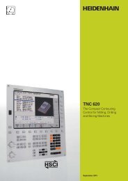
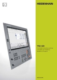
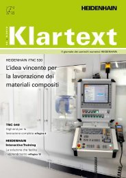
<strong>TNC</strong> <strong>320</strong><br />
The Compact Contouring<br />
Control for Milling, Drilling<br />
and Boring Machines<br />
September 2011
Contents<br />
The <strong>TNC</strong> <strong>320</strong>...<br />
Where can it be used? Compact and Versatile<br />
– The right control for milling, drilling and boring machines<br />
How does it look? Well Designed and User Friendly<br />
– The <strong>TNC</strong> <strong>320</strong> in dialog with the user<br />
What can it do? Minimize Setup and Nonmachining Time<br />
– The <strong>TNC</strong> <strong>320</strong> makes setup easy<br />
– The <strong>TNC</strong> <strong>320</strong> manages and measures<br />
Machining with Four Axes<br />
– Swivel head and rotary table controlled by the <strong>TNC</strong><br />
How is it programmed? Programming, Editing, Testing<br />
– The <strong>TNC</strong> <strong>320</strong> opens endless possibilities<br />
– Graphic support in any situation<br />
Programming in the Workshop<br />
– Straightforward function keys for complex contours<br />
– Programming contours unconventionally<br />
– Field-proven cycles for recurring operations<br />
– Reusing programmed contour elements<br />
– Fast availability of all information<br />
Open for Communication<br />
– Fast data transfer with the <strong>TNC</strong> <strong>320</strong><br />
– The <strong>TNC</strong> <strong>320</strong> programming station<br />
Are there any accessories? Workpiece Setup and Measurement<br />
– Setup, presetting and measuring with touch trigger probes<br />
... At a glance Overview<br />
– User functions<br />
– Specifi cations<br />
– Options<br />
– Accessories<br />
Tool Measurement<br />
– Measuring length, radius and wear right on the machine<br />
Positioning with the Electronic Handwheel<br />
– Delicate axis traverse<br />
3<br />
4<br />
6<br />
8<br />
12<br />
14<br />
16<br />
22<br />
24<br />
25<br />
26<br />
27
Compact and Versatile<br />
– The Right Control for Milling, Drilling and Boring Machines<br />
For more than 30 years, <strong>TNC</strong> controls<br />
from <strong>HEIDENHAIN</strong> have been proving<br />
themselves in daily use on milling, drilling<br />
and boring machines, and machining<br />
centers. While the controls have undergone<br />
continuous development during this period,<br />
the basic operational technique has<br />
remained the same.<br />
You will fi nd these principles implemented<br />
in the <strong>TNC</strong> <strong>320</strong> as well: shop-oriented<br />
programmability with graphic support,<br />
many fi eld-proven cycles and an<br />
operational design familiar from other<br />
<strong>HEIDENHAIN</strong> controls.<br />
4<br />
Shop-oriented programming<br />
You program conventional milling and drilling<br />
operations yourself at the machine, in plain<br />
language dialog—the workshop-oriented<br />
programming language from <strong>HEIDENHAIN</strong>.<br />
The <strong>TNC</strong> <strong>320</strong> provides you with optimum<br />
support with practical prompts, questions<br />
and graphical aids.<br />
Standard operations and even complex<br />
applications are on call as a large variety of<br />
real-world machining cycles or coordinate<br />
transformations.<br />
Simple operation<br />
For simple work, such as face milling, you<br />
need not write a program. With the<br />
<strong>TNC</strong> <strong>320</strong> it is just as easy to operate the<br />
machine manually by pressing the axis<br />
keys or—for maximum sensitivity—with<br />
the electronic handwheel.<br />
Offl ine program creation<br />
The <strong>TNC</strong> <strong>320</strong> can be programmed remotely<br />
just as well. Your Fast Ethernet interface<br />
guarantees very short transfer times, even<br />
of long programs.
The <strong>TNC</strong> <strong>320</strong> is compact and easy to<br />
read.<br />
The <strong>TNC</strong> <strong>320</strong> is a compact but versatile<br />
contouring control for three servo axes<br />
and servo spindle. A further servo axis<br />
is an option. Thanks to its fl exible<br />
operating concept—workshop-oriented<br />
programmability with <strong>HEIDENHAIN</strong><br />
conversational programming or offl ine<br />
programming—and its scope of features,<br />
it is especially suited for use on universal<br />
milling, drilling and boring machines for<br />
the following:<br />
Series and single-part production<br />
Toolmaking<br />
Machine building<br />
Research and development<br />
Prototypes and pilot plants<br />
Repair departments<br />
Training and education facilities<br />
And it offers the applicable features both<br />
necessary and helpful for:<br />
Universal milling machines<br />
Free contour programming<br />
Milling cycles for complex contours<br />
Fast presetting with <strong>HEIDENHAIN</strong> touch<br />
probes<br />
Drilling and boring machines<br />
Cycles for drilling, boring and spindle<br />
alignment<br />
Cycles for linear and circular point<br />
patterns<br />
Drilling oblique holes<br />
Machines with parallel secondary axes<br />
Compensating movement in the<br />
secondary axis U, V, W through the<br />
principal axis X, Y, Z<br />
Defi ning the principal and secondary axes<br />
in the NC program makes it possible to<br />
run programs on different machine<br />
confi gurations<br />
Including movements of parallel axes in<br />
the position display of the associated<br />
principal axis (sum display)<br />
5
Well Designed and User Friendly<br />
– The <strong>TNC</strong> <strong>320</strong> in Dialog with the User<br />
The monitor<br />
The TFT 15-inch color monitor shows a<br />
clear overview of all relevant information<br />
for programming, operating and inspecting<br />
the machine tool and control, such as<br />
program blocks, comments and error<br />
messages. More information is provided<br />
through graphic support during program<br />
entry, test run and actual machining.<br />
The selectable “split screen” display shows<br />
the part program blocks in one half of the<br />
screen and the graphics or the status<br />
display in the other half.<br />
During the course of the program, status<br />
displays will always offer information on<br />
tool position, the current program, active<br />
cycles and coordinate transformations, and<br />
other data. The <strong>TNC</strong> <strong>320</strong> even shows the<br />
current machining time.<br />
The keyboard<br />
As with all <strong>TNC</strong>s from <strong>HEIDENHAIN</strong>, the<br />
keyboard is tailored to the programming<br />
process. The well thought-out confi guration<br />
of keys facilitates program input. Simple<br />
words and abbreviations or unambiguous<br />
symbols clearly indicate each key’s<br />
function. Certain functions of the <strong>TNC</strong> <strong>320</strong><br />
are available by soft key.<br />
6
Keys on the monitor<br />
Select the screen layout<br />
Display machine mode or<br />
programming mode<br />
Soft keys for selecting<br />
functions on screen<br />
Shift between soft-key rows<br />
Keys on the control panel<br />
Program/fi le management,<br />
<strong>TNC</strong> functions<br />
Program management:<br />
Manipulate and delete<br />
programs<br />
Supplementary operating<br />
modes<br />
Help function<br />
Display error messages<br />
Show pocket calculator<br />
Machine operating modes<br />
Manual Operation<br />
Navigation and input<br />
Electronic Handwheel<br />
Positioning with Manual Data Input<br />
Program Run, Single Block<br />
Program Run, Full Sequence<br />
Navigation in dialogs<br />
Delete the last entered character<br />
Programming modes<br />
Programming and Editing<br />
Test Run with graphic simulation<br />
Straight line, chamfer<br />
Circular arc with center point<br />
Circular path with known radius<br />
Circular path starting tangentially<br />
Corner rounding<br />
Contour approach and departure<br />
Free contour programming<br />
Enter polar coordinates<br />
Enter incremental dimensions<br />
Entry of parameter instead of fi xed<br />
value/Defi nition of parameter<br />
Transfer actual position to program<br />
Defi nition and calling of tools<br />
Defi nition and calling of cycles<br />
Labeling and calling of subroutines<br />
and program repeats<br />
Programmable program call<br />
Programmed stop, interrupt/<br />
discontinue<br />
Touch probe functions<br />
Special functions, e.g. comments,<br />
structure<br />
Unambiguous keys make<br />
programming easy.<br />
Many functions are entered by<br />
soft key.<br />
With the gray path function keys<br />
and conversational guidance, you<br />
program line segments and<br />
circular arcs defi ned in various<br />
ways.<br />
Spindle speed and feed rate are<br />
easily adjusted.<br />
7
Minimize Setup and Nonmachining Time<br />
– The <strong>TNC</strong> <strong>320</strong> Makes Setup Easy<br />
Before you can begin machining, you must<br />
fi rst clamp the tool and set up the machine,<br />
fi nd the position and orientation of the<br />
workpiece on the machine, and set the<br />
workpiece reference point. Without<br />
support from the control this is often a<br />
time-consuming procedure, but it is<br />
indispensable. After all, any error directly<br />
reduces the machining accuracy. Particularly<br />
in small and medium-sized production runs,<br />
as well as for very large workpieces, setup<br />
times become quite a signifi cant factor.<br />
Here the <strong>TNC</strong> <strong>320</strong> shows its strengths:<br />
With its practice-oriented setup features it<br />
supports the operator and helps to reduce<br />
nonmachining time. Together with the<br />
touch probes, the <strong>TNC</strong> <strong>320</strong> offers various<br />
probing features for aligning, presetting,<br />
and measuring the workpieces.<br />
8<br />
Delicate manual traverse<br />
For setup, you can use the direction keys<br />
to move the machine axes manually or in<br />
incremental jog. A simpler and more<br />
reliable way, however, is to use the<br />
electronic handwheels from <strong>HEIDENHAIN</strong><br />
(see page 26). Particularly with the portable<br />
handwheels you are always close to the<br />
action, enjoy a close-up view of the setup<br />
process, and can control the infeed<br />
responsively and precisely.<br />
Workpiece alignment<br />
With <strong>HEIDENHAIN</strong> touch probes (see<br />
page 24) and the probing functions of the<br />
<strong>TNC</strong> <strong>320</strong>, you can forgo any tedious<br />
manual alignment of the workpiece:<br />
Clamp the workpiece in any position.<br />
The touch probe ascertains the<br />
workpiece misalignment by probing a<br />
surface, two holes, or two studs.<br />
The <strong>TNC</strong> <strong>320</strong> compensates the<br />
misalignment with a “basic rotation,”<br />
which means that in the NC program the<br />
part is rotated by the measured<br />
misalignment.<br />
Compensating workpiece misalignment<br />
Compensate misalignment by rotating the<br />
coordinate system or turning the table
Workpiece presetting<br />
You can use a reference point to assign a<br />
defi ned value in the <strong>TNC</strong> display to any<br />
workpiece position. Finding this point<br />
quickly and reliably reduces nonproductive<br />
time and increases machining accuracy.<br />
The <strong>TNC</strong> <strong>320</strong> features probing cycles for<br />
automatic presetting. Once found, you can<br />
save reference points<br />
in the workpiece preset table,<br />
in a workpiece datum table, or<br />
by directly setting the displayed value.<br />
Workpiece presetting<br />
At a corner, for example, or in the center of<br />
a bolt hole circle<br />
Preset table: The <strong>TNC</strong> <strong>320</strong>’s central<br />
reference point management<br />
The preset table makes fl exible machining,<br />
shorter setup times and increased<br />
productivity possible. In other words, it<br />
makes it much easier to set up the<br />
machine.<br />
In the preset table you can save any<br />
number of reference points and assign an<br />
individual basic rotation to each one.<br />
There are three ways to save reference<br />
points in the preset table:<br />
In the Manual mode by soft key<br />
By using the probing functions<br />
With the automatic probing cycles<br />
9
Minimize Setup and Nonmachining Time<br />
– The <strong>TNC</strong> <strong>320</strong> Manages and Measures<br />
The difference in requirements placed<br />
on the classical machine for tool and<br />
mold-making and machining centers are<br />
becoming ever less distinct. Of course<br />
the <strong>TNC</strong> <strong>320</strong> is capable of controlling<br />
automated manufacturing processes. It<br />
has the functions required to manage and<br />
measure tools and inspect the machining<br />
process. It helps you reduce non-cutting<br />
time, increase productivity and improve<br />
production quality.<br />
10<br />
Inspecting workpieces for proper<br />
machining and dimensional accuracy<br />
The <strong>TNC</strong> <strong>320</strong> features a number of<br />
measuring cycles for checking the<br />
geometry of the machined workpieces.<br />
To run the measuring cycles, you simply<br />
insert a touch probe from <strong>HEIDENHAIN</strong><br />
(see page 24) into the spindle in place of a<br />
tool. This enables you to<br />
recognize a workpiece and call the<br />
appropriate part program,<br />
check whether all machining operations<br />
were conducted correctly,<br />
determine infeeds for fi nishing,<br />
detect and compensate tool wear,<br />
and ascertain machining error trends.<br />
Length measurement<br />
Circular pocket/hole measurement<br />
Measuring the angle of a plane
Workpiece measurement and automatic<br />
compensation of tool data<br />
Together with the TT 140 touch probe for<br />
tool measurement (see page 25) the<br />
<strong>TNC</strong> <strong>320</strong> can automatically measure tools<br />
while they are in the machine. The <strong>TNC</strong> <strong>320</strong><br />
saves the ascertained values of tool length<br />
and radius in the central tool fi le. By<br />
inspecting the tool during machining you<br />
can quickly and directly measure wear or<br />
breakage to prevent scrap or rework. If<br />
the measured deviations lie outside the<br />
tolerances, or if the monitored life of the<br />
tool is exceeded, the <strong>TNC</strong> <strong>320</strong> locks the<br />
tool and automatically inserts a<br />
replacement tool.<br />
Measuring the tool radius<br />
Measuring the tool length<br />
Measuring tool wear<br />
Tool management<br />
For machining centers with automatic tool<br />
changers, the <strong>TNC</strong> <strong>320</strong> offers a central tool<br />
memory for any number of tools. The tool<br />
memory is a freely confi gurable fi le and<br />
can therefore be optimally fi tted to your<br />
needs. You can even have the <strong>TNC</strong> <strong>320</strong><br />
manage your tool names. The control<br />
prepares the next tool change while the<br />
current tool is still cutting. This signifi cantly<br />
reduces the non-cutting time required for<br />
changing tools.<br />
11
Machining with Four Axes<br />
– Swivel Head and Rotary Table Controlled by the <strong>TNC</strong> (Option)<br />
Many fi ve-axis operations that at fi rst<br />
glance may seem very complex can be<br />
reduced to conventional 2-D movements<br />
that are simply tilted about one or more<br />
rotary axes or wrapped onto a cylindrical<br />
surface. The <strong>TNC</strong> supports you with<br />
application-oriented functions to help you<br />
write and edit such programs quickly and<br />
simply without a CAD/CAM system.<br />
12<br />
Tilting the working plane*<br />
Programs for contours and holes on<br />
inclined surfaces are often very complex<br />
and require time-consuming computing<br />
and programming work. Here the <strong>TNC</strong> <strong>320</strong><br />
helps you to save a great deal of<br />
programming time.<br />
You program the part as usual in the<br />
working plane (e.g. the X/Y plane), but it is<br />
machined in a plane that is rotated in one<br />
or more axes about the main plane.<br />
The PLANE feature makes it easy to defi ne<br />
a tilted working plane: You can specify tilted<br />
working planes in seven different ways,<br />
depending on the information on the<br />
workpiece drawing. Clearly arranged<br />
support graphics assist you during input.<br />
You can defi ne the positioning behavior<br />
with the PLANE function so that there are<br />
no unpleasant surprises when the program<br />
is run. The settings for defi ning the<br />
positioning behavior are identical for all<br />
PLANE functions, making everything that<br />
much easier.
Machining cylindrical surfaces*<br />
With the <strong>TNC</strong> <strong>320</strong> it is quite easy to<br />
program contours (which consist of straight<br />
lines and arcs) on cylindrical surfaces using<br />
rotary and tilting tables: You simply<br />
program the contour in a plane as if the<br />
cylinder surface were unrolled. You enter a<br />
contour in two dimensions—as if in a<br />
plane—and the <strong>TNC</strong> <strong>320</strong> then calculates<br />
and machines the corresponding cylindrical<br />
contour.<br />
The <strong>TNC</strong> <strong>320</strong> features three cycles for<br />
cylindrical surface machining:<br />
Slot milling (the slot width is the same as<br />
the tool diameter)<br />
Guide-groove milling (the slot width is<br />
greater than the tool diameter)<br />
Ridge milling<br />
* The machine must be prepared by the machine tool<br />
builder for this function.<br />
13
Programming, Editing, Testing<br />
– The <strong>TNC</strong> <strong>320</strong> Opens Endless Possibilities<br />
The <strong>TNC</strong> <strong>320</strong> is just as universal in<br />
application as it is fl exible in machining and<br />
programming.<br />
Positioning with Manual Data Input<br />
You can start working with the <strong>TNC</strong> <strong>320</strong><br />
even before writing a complete part<br />
program. Simply machine a part step by<br />
step—switching as you want between<br />
manual operation and automatic<br />
positioning.<br />
Programming at the machine<br />
<strong>HEIDENHAIN</strong> controls are workshop<br />
oriented, which means that they were<br />
conceived for programming right at the<br />
machine. With conversational<br />
programming you can forget about<br />
memorizing G codes. Instead you use<br />
dedicated keys and soft keys to program<br />
line segments, circular arcs and cycles. With<br />
a keystroke, you initiate a <strong>HEIDENHAIN</strong><br />
plain language dialog, and the <strong>TNC</strong> begins<br />
immediately to support you actively in your<br />
work. Unambiguous questions and prompts<br />
help you enter all the required information.<br />
If you are used to DIN/ISO programming,<br />
however, the <strong>TNC</strong> <strong>320</strong> is still the right<br />
control for you. It displays soft-key rows<br />
dedicated to the most important DIN/ISO<br />
commands. Or you connect a USB<br />
keyboard and use it to write the program.<br />
Whether plain-language prompts, dialog<br />
guidance, programming steps or soft keys,<br />
all texts are available in all numerous<br />
languages.<br />
Creating programs offl ine<br />
The <strong>TNC</strong> <strong>320</strong> is also well equipped for<br />
offl ine programming. It can be integrated<br />
through its interfaces into networks and<br />
connected with programming stations or<br />
other data storage devices. The <strong>TNC</strong> <strong>320</strong><br />
can also run programs that were written in<br />
DIN/ISO format.<br />
14
– Graphic Support in Any Situation<br />
Programming graphics<br />
The two-dimensional programming graphics<br />
give you additional security: while you are<br />
programming, the <strong>TNC</strong> <strong>320</strong> draws every<br />
entered traverse command on the screen.<br />
Program verifi cation graphics<br />
To play it safe before running a program,<br />
the <strong>TNC</strong> <strong>320</strong> can graphically simulate the<br />
machining of the workpiece. It can display<br />
the simulation in the following ways:<br />
In a plan view with different shades of<br />
depth<br />
In three planes (as in the workpiece<br />
drawing)<br />
In a solid model, 3-D view<br />
Details can be displayed in magnifi cation.<br />
In addition, the <strong>TNC</strong> <strong>320</strong> indicates the<br />
calculated machining time in hours,<br />
minutes and seconds.<br />
Program-run graphics<br />
On the <strong>TNC</strong> <strong>320</strong>, you can run the<br />
programming graphics or verifi cation<br />
graphics even while the workpiece is being<br />
machined. Also, it shows a real-time<br />
graphic of the machining progress during<br />
program run. Coolant spray and protective<br />
enclosures usually obstruct any direct view<br />
of the actual workpiece. You can get around<br />
this with a simple keystroke to see the<br />
simulated progress of workpiece<br />
machining.<br />
Help graphics<br />
During cycle programming in the<br />
plain-language dialog, the <strong>TNC</strong> shows a<br />
separate illustration for each parameter.<br />
This makes it easier to understand the<br />
function and accelerates programming.<br />
15
Programming in the Workshop<br />
– Straightforward Function Keys for Complex Contours<br />
Programming 2-D Contours<br />
Two-dimensional contours are the daily<br />
bread of the modern machine shop. Here<br />
the <strong>TNC</strong> <strong>320</strong> offers a variety of possibilities.<br />
Programming with path function keys<br />
If contours are dimensioned for NC, which<br />
means that the end points are specifi ed in<br />
Cartesian or polar coordinates, then you<br />
can program them directly with the path<br />
function keys.<br />
16<br />
Straight and circular contour elements<br />
To program a line segment, for example,<br />
simply press the key for linear traverse. The<br />
<strong>TNC</strong> <strong>320</strong> asks for all information required<br />
for a complete programming block, such as<br />
target coordinates, feed rate, cutter radius<br />
compensation and machine functions.<br />
Appropriate path function keys for circular<br />
movement, chamfers, and corner rounding<br />
simplify your programming. To avoid<br />
surface blemishes during approach or<br />
departure from the contour, it must be<br />
approached smoothly—that is, tangentially.<br />
Circular path defi ned<br />
by its end point, with<br />
a smooth (tangential)<br />
departure from the<br />
previous contour<br />
element<br />
Circular path defi ned<br />
by its center point,<br />
end point, and<br />
rotational direction<br />
Circular path defi ned<br />
by its radius, end point<br />
and rotational<br />
direction<br />
You simply specify the starting or end point<br />
of the contour and the approaching or<br />
departing radius of the cutter edge—the<br />
control does the rest for you.<br />
The <strong>TNC</strong> <strong>320</strong> can look ahead over a<br />
radius-compensated contour for up to<br />
99 blocks to watch for back cutting and<br />
avoid contour damage such as can occur<br />
when roughing a contour with a large tool.<br />
Straight line defi ned<br />
by its end point<br />
Rounding: circular<br />
path defi ned by<br />
radius and corner point,<br />
with a smooth<br />
(tangential) transition to<br />
its adjoining contour<br />
elements<br />
Chamfer:<br />
defi ned by the<br />
corner point and the<br />
chamfer length
– Programming Contours Unconventionally<br />
FK free contour programming<br />
Not all workpieces are dimensioned for<br />
conventional NC programming. Thanks to<br />
FK, the control’s free contour programming<br />
feature, in such cases you simply type in<br />
the known data—without fi rst having to<br />
convert or calculate your data! It does not<br />
matter if individual contour elements are<br />
not completely defi ned as long as the<br />
complete contour has been. If the given<br />
data result in more than one mathematical<br />
solution, the helpful <strong>TNC</strong> <strong>320</strong> programming<br />
graphics present the possible variants for<br />
your selection.<br />
17
Programming in the Workshop<br />
– Field-Proven Cycles for Recurring Operations<br />
Comprehensive Fixed Cycles for<br />
Milling, Drilling and Boring<br />
Frequently recurring operations that<br />
comprise several working steps are stored<br />
in the <strong>TNC</strong> <strong>320</strong> as cycles. You program<br />
them under conversational guidance and<br />
are supported by graphics that clearly<br />
illustrate the required input parameters.<br />
Standard cycles<br />
Besides the fi xed cycles for drilling, tapping<br />
(with or without fl oating tap holder), thread<br />
milling, reaming and boring, there are cycles<br />
for hole patterns and milling cycles for<br />
clearing plane surfaces, and for roughing<br />
and fi nishing pockets, slots and studs.<br />
Cycles for complex contours<br />
Subcontour List cycles (SL) are particularly<br />
helpful for clearing pockets with combined<br />
contours. This expression denotes fi xed<br />
cycles for pilot drilling, roughing and<br />
fi nishing in which the contour or contour<br />
segments are defi ned in subprograms. In<br />
this way, one contour description can be<br />
used for more than one operation using<br />
different tools.<br />
Up to twelve subcontours can be<br />
superimposed for machining. The control<br />
automatically calculates the resulting<br />
contour and the tool paths for roughing or<br />
clearing the surfaces. Subcontours can be<br />
pockets or islands. Different components<br />
are combined to form a single pocket in<br />
which the tool avoids the islands.<br />
The <strong>TNC</strong> <strong>320</strong> maintains a fi nishing<br />
allowance on the wall and fl oor surfaces<br />
during roughing. When roughing with<br />
different tools, the control identifi es<br />
material remaining in inside corners so that<br />
it can be cleared later with smaller tools. A<br />
separate cycle is used for milling to the<br />
fi nished dimension.<br />
18
OEM cycles<br />
As original equipment manufacturers<br />
(OEMs), machine tool builders can<br />
contribute their special manufacturing<br />
know-how by designing additional fi xed<br />
cycles and saving them in the <strong>TNC</strong> <strong>320</strong>.<br />
However, the end user can write his own<br />
cycles as well. <strong>HEIDENHAIN</strong> makes this<br />
possible with its PC program CycleDesign.<br />
CycleDesign enables you to organize the<br />
input parameters and soft-key structure of<br />
the <strong>TNC</strong> <strong>320</strong> to suit your own needs.<br />
3-D machining with parametric<br />
programming<br />
With parameter functions you can program<br />
simple 3-D geometric fi gures that can easily<br />
be described mathematically. Here you can<br />
use the basic arithmetical operations,<br />
trigonometric functions, roots, powers,<br />
logarithmic functions, parentheses, and<br />
logical comparisons with conditional jump<br />
instructions. Parametric programming also<br />
offers you a simple method of realizing 3-D<br />
operations for which there are no standard<br />
cycles. Of course, parametric programming<br />
is also suited for 2-D contours that cannot<br />
be described with line segments or circular<br />
arcs, but rather through mathematical<br />
functions.<br />
Stay simple and fl exible when<br />
programming machining patterns<br />
Machining positions are often arranged in<br />
patterns on the workpiece. With the<br />
<strong>TNC</strong> <strong>320</strong>, you can program very diverse<br />
machining patterns simply and extremely<br />
fl exibly—of course with graphic support.<br />
You can defi ne as many point patterns as<br />
desired with various numbers of points.<br />
19
Programming in the Workshop<br />
– Reusing Programmed Contour Elements<br />
Coordinate transformation<br />
If you should need a contour that has<br />
already been programmed at another<br />
position or in a different size, the <strong>TNC</strong> <strong>320</strong><br />
offers you a simple solution: coordinate<br />
transformation.<br />
With coordinate transformation you can,<br />
for example, rotate or mirror the<br />
coordinate system, or shift the datum.<br />
With a scaling factor you can enlarge or<br />
reduce contours to respect shrinkage<br />
allowances or oversizes.<br />
Program section repeats, subprograms,<br />
program calls<br />
Many machining operations repeat<br />
themselves either on the same workpiece<br />
or on different workpieces. Once you<br />
have programmed a detail there is no<br />
reason to have to program it again. With<br />
its subprogramming feature, the <strong>TNC</strong> can<br />
save you a great deal of programming<br />
time.<br />
In program section repetition, you label<br />
a section of the program and during<br />
program run the <strong>TNC</strong> repeats the section<br />
successively as many times as required.<br />
You can mark a program section as a<br />
subprogram and then call it at any point<br />
in the program and as often as you want.<br />
With the program call function you can<br />
even use a completely separate program at<br />
any place in your current program. This gives<br />
you convenient access to pre-programmed,<br />
frequently needed working steps or<br />
contours.<br />
Of course you can also combine these<br />
programming techniques.<br />
20
– Fast Availability of All Information<br />
Do you have questions on a programming<br />
step but your User’s Manual is not at hand?<br />
No problem: The <strong>TNC</strong> <strong>320</strong> numerical control<br />
and <strong>TNC</strong> <strong>320</strong> programming station now<br />
feature <strong>TNC</strong>guide, a convenient help system<br />
that can show the user documentation in a<br />
separate window.<br />
You can activate the <strong>TNC</strong>guide by simply<br />
pressing the help key on the <strong>TNC</strong> keyboard<br />
or by clicking any soft key with a cursor in<br />
the shape of a question mark. You switch<br />
the cursor by simply clicking the help<br />
symbol ( ) that appears on all <strong>TNC</strong><br />
screens.<br />
<strong>TNC</strong>guide usually displays the information<br />
in the immediate context of the element in<br />
question (context-sensitive help). This<br />
means that you immediately receive the<br />
relevant information. This function is<br />
particularly helpful with the soft keys.<br />
The method and effect of operation is<br />
explained in detail.<br />
You can download the documentation in the<br />
desired language from the <strong>HEIDENHAIN</strong><br />
homepage into the corresponding language<br />
directory on the <strong>TNC</strong> hard disk.<br />
The following manuals are available in the<br />
help system:<br />
User’s Manual for Conversational<br />
Programming<br />
User’s Manual for Cycle Programming<br />
User’s Manual for DIN/ISO Programming<br />
User’s Manual for the <strong>TNC</strong> <strong>320</strong><br />
Programming Station (only included in<br />
the programming station)<br />
<strong>TNC</strong>guide integrated in the control, e.g. on the <strong>TNC</strong> <strong>320</strong> ...<br />
… or at the programming station<br />
21
Open for Communication<br />
– Fast Data Transfer with the <strong>TNC</strong><br />
The networked <strong>TNC</strong> <strong>320</strong><br />
The <strong>TNC</strong> <strong>320</strong> can be integrated into<br />
networks and connected with PCs,<br />
programming stations and other data<br />
storage devices. Even in its standard<br />
version, the <strong>TNC</strong> <strong>320</strong> features a latestgeneration<br />
Fast Ethernet interface in<br />
addition to its RS-232-C/V.24 data interface.<br />
The <strong>TNC</strong> <strong>320</strong> communicates with NFS<br />
servers and Windows networks in TCP/IP<br />
protocol without needing additional<br />
software. The fast data transfer at rates of<br />
up to 100 Mbps guarantees very short<br />
transfer times.<br />
The transmitted programs are saved in the<br />
internal memory of the <strong>TNC</strong> <strong>320</strong> and are<br />
run from it at high speed.<br />
For well-organized program management on<br />
your control, simply place the individual fi les<br />
in directories (folders). You can structure the<br />
respective directories through individual<br />
subdirectories.<br />
22<br />
Company Network<br />
Programming<br />
system<br />
<strong>TNC</strong> <strong>320</strong><br />
Ethernet<br />
interface<br />
<strong>TNC</strong> 620<br />
Ethernet<br />
interface<br />
i<strong>TNC</strong> 530<br />
Ethernet<br />
interface<br />
Programs for data transfer<br />
With the aid of the free PC program<br />
<strong>TNC</strong>remo from <strong>HEIDENHAIN</strong> and an<br />
Ethernet or other data interface you can<br />
transfer remotely stored part programs<br />
and tool or pallet tables bidirectionally<br />
make backups.<br />
With the powerful <strong>TNC</strong>remoPlus software<br />
you can also transfer the screen contents<br />
of the control to your PC by means of the<br />
live-screen function.
– The <strong>TNC</strong> <strong>320</strong> Programming Station<br />
Why a programming station?<br />
It’s well known that it is easy to create part<br />
programs on a <strong>TNC</strong> <strong>320</strong> at the machine,<br />
even while another part is being machined.<br />
Nevertheless, it can often happen that<br />
short reloading times and other machining<br />
tasks hinder any prolonged or concentrated<br />
programming work. With the <strong>TNC</strong> <strong>320</strong><br />
programming station you have the<br />
capability to program just as you do at the<br />
machine, but away from the noise and<br />
distractions of the shop fl oor.<br />
Creating programs<br />
Programming, testing and optimizing<br />
<strong>HEIDENHAIN</strong> conversational or DIN/ISO<br />
programs for the <strong>TNC</strong> <strong>320</strong> with the<br />
programming station substantially reduces<br />
machine idle times. You need not adjust<br />
your way of thinking—every keystroke fi ts.<br />
On the programming station you program<br />
on the same keyboard as at the machine.<br />
Testing programs created offl ine<br />
Of course you can also test programs that<br />
were written on a CAD/CAM system. The<br />
various views of the program verifi cation<br />
graphics help you to easily spot contour<br />
damage and hidden details.<br />
Training with the <strong>TNC</strong> <strong>320</strong> programming<br />
station<br />
Because the <strong>TNC</strong> <strong>320</strong> programming station<br />
is based on the same software as the<br />
<strong>TNC</strong> <strong>320</strong>, it is ideally suited for apprentice<br />
and advanced training. The program is<br />
entered on the original keyboard unit. Even<br />
the test run functions exactly as it does on<br />
the machine. This gives the trainee the<br />
experience needed to enable him to safely<br />
operate the machine later.<br />
Because it can be programmed with<br />
smarT.NC, in plain language, and in DIN/<br />
ISO, the <strong>TNC</strong> <strong>320</strong> programming station is<br />
very well suited in schools for <strong>TNC</strong><br />
programming training.<br />
More information about the programming<br />
station and a free demo version is<br />
available on the Internet at<br />
www.heidenhain.de. Or simply ask for<br />
the <strong>TNC</strong> <strong>320</strong> Programming Station CD or<br />
brochure.<br />
Your workstation<br />
The programming station software runs on<br />
a PC. The PC screen shows you the <strong>TNC</strong><br />
user interface as on the control, and offers<br />
the familiar graphic support. Depending on<br />
the version of the programming station,<br />
there are several types of possibilities for<br />
using it.<br />
The free demo version contains all<br />
functions of the <strong>TNC</strong> <strong>320</strong>, and permits<br />
short programs to be saved. It is<br />
programmed over the PC keyboard.<br />
Programming station with <strong>TNC</strong> operating panel<br />
On the version with the TE 520B <strong>TNC</strong><br />
operating panel you create your programs<br />
as always, on a keyboard with the same<br />
function keys as the control on the<br />
machine. It also has a PC keyboard for<br />
G-code programming, fi le names and<br />
comments.<br />
But you can also work without the <strong>TNC</strong><br />
operating panel: a virtual keyboard<br />
simulating the TE appears on the PC<br />
screen with the <strong>TNC</strong> <strong>320</strong>’s most important<br />
dialog initiation keys.<br />
23
Workpiece Measurement<br />
– Setup, Datum Setting and Measuring<br />
with Touch Trigger Probes<br />
Workpiece touch probes from <strong>HEIDENHAIN</strong><br />
help you to reduce costs in the workshop<br />
and in series production: Together with the<br />
<strong>TNC</strong> <strong>320</strong>, touch probes can automatically<br />
perform setup, measuring and inspection<br />
functions.<br />
The stylus of a TS touch trigger probe is<br />
defl ected upon contact with a workpiece<br />
surface. At that moment the TS generates<br />
a trigger signal that, depending on the<br />
model, is transmitted either by cable or<br />
over an infrared beam to the control.<br />
The touch probes* are inserted directly into<br />
the machine tool spindle. They can be<br />
equipped with various shanks depending<br />
on the machine. The ruby ball tips are<br />
available in several diameters, and the styli<br />
in different lengths.<br />
* The touch probes must be interfaced to the <strong>TNC</strong> <strong>320</strong><br />
by the machine tool builder.<br />
24<br />
TS 220<br />
Touch probe with cable connection for<br />
signal transmission for machines with<br />
manual tool change:<br />
TS 220 – TTL version<br />
Touch probes with infrared signal<br />
transmission for machines with automatic<br />
tool change:<br />
TS 440 – Compact dimensions<br />
TS 444 – Compact dimensions, battery-free<br />
power supply through integrated air turbine<br />
generator over central compressed air<br />
supply<br />
TS <strong>640</strong> – Standard touch probe with<br />
wide-range infrared transmission<br />
TS 740 – High probing accuracy and<br />
repeatability, low probing force<br />
TS <strong>640</strong><br />
TS 440<br />
SE <strong>640</strong><br />
More information about workpiece touch<br />
probes is available on the Internet at<br />
www.heidenhain.de or in the Touch<br />
Probes brochure or CD.
Tool Measurement<br />
– Measuring Length, Radius and Wear Directly in the Machine<br />
The tool is of course a defi nitive factor in<br />
ensuring a consistently high level of<br />
production quality. This means that an<br />
exact measurement of the tool dimensions<br />
and periodic inspection of the tool for wear<br />
and breakage, as well as the shape of each<br />
tooth, are necessary. A suitable touch<br />
trigger probe for tool measurement is the<br />
TT 140*. It is installed directly in the<br />
machine’s workspace, where it permits<br />
tool measurement either before machining<br />
or during interruptions.<br />
The TT 140 tool touch probe captures the<br />
tool length and radius. When probing the<br />
tool, either while rotating or at standstill<br />
(such as for measuring individual teeth),<br />
the contact plate is defl ected and a trigger<br />
signal is transmitted to the <strong>TNC</strong> <strong>320</strong>.<br />
* The touch probe must be interfaced to the <strong>TNC</strong> <strong>320</strong><br />
by the machine tool builder.<br />
More information about tool touch<br />
probes is available on the Internet at<br />
www.heidenhain.de or in the Touch<br />
Probes brochure or CD.<br />
TT 140<br />
25
Positioning with the Electronic Handwheel<br />
– Delicate Axis Traverse<br />
To set up the workpiece you can use the<br />
direction keys to move the machine axes<br />
manually or in incremental jog. A simpler<br />
and more sensitive way, however, is to<br />
use the electronic handwheels from<br />
<strong>HEIDENHAIN</strong>.<br />
You can move the axis slide through the<br />
feed motors in direct relation to the<br />
rotation of the handwheel. For delicate<br />
operations you can set the transmission<br />
ratio to certain preset distances per<br />
handwheel revolution.<br />
HR 130 and HR 150 panel-mounted<br />
handwheels<br />
The panel-mounted handwheels from<br />
<strong>HEIDENHAIN</strong> can be integrated in the<br />
machine operating panel or mounted at<br />
another location on the machine. An<br />
adapter permits connection of up to<br />
three HR 150 electronic handwheels.<br />
26<br />
HR 410<br />
HR 410 portable handwheel<br />
If you need to get a closer look at the<br />
workpiece in the machine’s working<br />
envelope, then ideally you should use the<br />
HR 410 portable handwheel. The axis keys<br />
and certain function keys are integrated in<br />
the housing, so you can switch axes and set<br />
up the machine at any time—regardless of<br />
where you happen to be standing.<br />
The following functions are available:<br />
Traverse direction keys<br />
Three keys with preset feed rates for<br />
latched traverse<br />
Actual-position-capture key<br />
Three keys for machine functions to be<br />
defi ned by the machine tool builder<br />
Permissive buttons<br />
Emergency stop button
Overview<br />
– Specifi cations<br />
Specifi cations<br />
Components Main computer with <strong>TNC</strong> keyboard and integrated 15.1-inch TFT color fl at-panel display with soft keys<br />
Operating system HEROS real-time operating system for machine control<br />
Memory 300 MB (on compact fl ash memory card CFR)<br />
Input resolution and<br />
display step<br />
Linear axes: up to 1 µm<br />
Angular axes: to 0.001°<br />
Input range Maximum: 99 999.999 mm or 99 999.999°<br />
Interpolation Linear in 4 axes<br />
Circular in 2 axes<br />
Circular in 3 axes with tilted working plane<br />
Helical: superimposition of circular and straight paths<br />
Block processing time 6 ms (3-D straight line without radius compensation)<br />
Axis feedback control Position loop resolution: Signal period of the position encoder/1024<br />
Cycle time of position controller: 3 ms<br />
Range of traverse Maximum: 100 m<br />
Spindle speed Maximum: 100000 rpm (analog speed command signal)<br />
Error compensation Linear and nonlinear axis error, backlash, reversal spikes during circular movements, thermal expansion<br />
Stick-slip friction<br />
Data interfaces RS-232-C/V.24 max. 115 kbps<br />
Extended data interface with LSV2 protocol for remote operation of the <strong>TNC</strong> <strong>320</strong> over the data interface<br />
with the <strong>HEIDENHAIN</strong> software <strong>TNC</strong>remo or <strong>TNC</strong>remoPlus<br />
100BaseT Fast Ethernet interface<br />
3 x USB 2.0<br />
Diagnostics Fast and simple troubleshooting through integrated diagnostic aids<br />
Ambient temperature Operation: +5 °C to +45 °C<br />
Storage: –35 °C to +65 °C<br />
27
Overview<br />
– User Functions<br />
User functions<br />
Brief description<br />
28<br />
Standard<br />
Option<br />
<br />
<br />
Basic version: 3 axes plus closed-loop spindle<br />
1st additional axis for 4 axes and open-loop or closed-loop spindle<br />
2nd additional axis for 5 axes and open-loop spindle<br />
Program entry In <strong>HEIDENHAIN</strong> conversational format and DIN/ISO over soft keys or USB keyboard<br />
Position data coordinates Nominal positions for lines and arcs in Cartesian coordinates or polar coordinates<br />
Incremental or absolute dimensions<br />
Display and input in mm or inches<br />
Tool compensation Tool radius in the working plane and tool length<br />
Radius-compensated contour look-ahead for up to 99 blocks (M120)<br />
Tool tables Multiple tool tables with any number of tools<br />
Constant contouring speed Relative to the path of the tool center<br />
Relative to the tool’s cutting edge<br />
Parallel operation Creating a program with graphical support while another program is being run<br />
Rotary table machining 8<br />
8<br />
Programming of cylindrical contours as if in two axes<br />
Feed rate in mm/min<br />
Contour elements Straight line<br />
Chamfer<br />
Circular path<br />
Circle center point<br />
Circle radius<br />
Tangentially connecting circular arc<br />
Corner rounding<br />
Approaching and<br />
departing the contour<br />
FK free contour<br />
programming<br />
Via straight line: tangential or perpendicular<br />
Via circular arc<br />
Program jumps Subroutines<br />
Program section repeats<br />
Calling any program as subroutine<br />
FK free contour programming in <strong>HEIDENHAIN</strong> conversational format with graphic support for<br />
workpiece drawings not dimensioned for NC<br />
Fixed cycles Cycles for drilling, pecking, reaming, boring, counterboring, conventional and rigid tapping<br />
Cycles for milling internal and external threads<br />
Rectangular and circular pockets<br />
Cycles for clearing level and inclined surfaces<br />
Multioperation machining of straight and circular slots<br />
Multioperation machining of rectangular and circular pockets<br />
Linear and circular point patterns<br />
Contour train, contour-parallel contour pocket<br />
OEM cycles (special cycles developed by the machine tool builder) can be integrated<br />
Coordinate transformation<br />
8<br />
Datum shift, rotation, mirror image, scaling factor (axis-specifi c)<br />
Tilting the working plane, PLANE function
User functions<br />
Q parameters<br />
Programming<br />
with variables<br />
Standard<br />
Option<br />
Mathematical functions =, +, –, *, /, sin Þ, cos Þ, angle Þ of sin Þ and cos Þ, √a, √a 2 + b 2<br />
Logical operations (=, = /, )<br />
Calculating with parentheses<br />
tan Þ, arc sin, arc cos, arc tan, a n , e n , In, log, absolute value of a number, constant þ, negation,<br />
truncation of digits before or after the decimal point<br />
Functions for calculation of circles<br />
Programming aids Calculator<br />
Complete list of all current error messages<br />
Context-sensitive help function for error messages<br />
<strong>TNC</strong>guide: The integrated help system. User information available directly on the i<strong>TNC</strong> <strong>320</strong><br />
Graphical support for programming cycles<br />
Comment and structure blocks in the NC program<br />
Actual position capture Actual positions can be transferred directly into the NC program<br />
Program verifi cation<br />
graphics<br />
Display modes<br />
Graphic simulation before a program run, even while another program is running<br />
Plan view / projection in 3 planes / 3-D view, also in tilted working plane<br />
Magnifi cation of details<br />
Programming graphics In the Programming and Editing mode, the contour of the NC blocks is drawn on screen while the<br />
blocks are being entered (2-D pencil-trace graphics), even while another program is running<br />
Program-run graphics<br />
Display modes<br />
Graphic simulation during real-time machining<br />
Plan view / projection in 3 planes / 3-D view<br />
Machining time Calculation of machining time in the Test Run operating mode<br />
Display of the current machining time in the Program Run operating mode<br />
Returning to the contour Mid-program startup in any block in the program, returning the tool to the calculated nominal<br />
position to continue machining<br />
Program interruption, contour departure and return<br />
Preset tables One preset table for storing reference points<br />
Datum tables Several datum tables for storing workpiece-related datums<br />
Touch probe cycles Touch probe calibration<br />
Compensating workpiece misalignment<br />
Datum setting, manual or automatic<br />
Automatic tool and workpiece measurement<br />
Parallel secondary axes Compensating movement in the secondary axis U, V, W through the principal axis X, Y, Z<br />
Including movements of parallel axes in the position display of the associated principal axis<br />
(sum display)<br />
Defi ning the principal and secondary axes in the NC program makes it possible to run programs<br />
on different machine confi gurations<br />
Conversational languages<br />
41<br />
English, Chinese (traditional, simplifi ed), Czech, Danish, Dutch, Finnish, French, German,<br />
Hungarian, Italian, Polish, Portuguese, Russian (Cyrillic), Spanish, Swedish<br />
For more conversational languages, see Options<br />
29
– Options, Accessories<br />
Option Option<br />
number<br />
Accessories<br />
Electronic handwheels One HR 410 portable handwheel or<br />
One HR 130 panel-mounted handwheel or<br />
Up to three HR 150 panel-mounted handwheels via the HRA 110 handwheel adapter<br />
Workpiece measurement • TS 220 touch trigger probe with cable connection or<br />
• TS 440 touch trigger probe with infrared transmission or<br />
• TS 444 touch trigger probe with infrared transmission or<br />
• TS <strong>640</strong> touch trigger probe with infrared transmission or<br />
• TS 740 touch trigger probe with infrared transmission<br />
Tool measurement • TT 140 triggering touch probe<br />
Software for PCs • TeleService: Software for remote diagnosis, monitoring, and operation<br />
• <strong>TNC</strong>diag: Software for fast and easy fault diagnosis<br />
• CycleDesign: Software for creating your own cycle structure<br />
• <strong>TNC</strong>remo: Software for data transfer—free of charge<br />
• <strong>TNC</strong>remoPlus: Software for data transfer with live-screen function<br />
<strong>TNC</strong> <strong>320</strong> programming<br />
station<br />
30<br />
As of<br />
NC software<br />
340 551-<br />
ID Comment<br />
Additional axis – 01 – 1st additional axis for 4 axes and open-loop or closed-loop spindle<br />
2nd additional axis for 5 axes and open-loop spindle<br />
Software option 1 8 01 536 164-01 Rotary table machining<br />
Programming of cylindrical contours as if in two axes<br />
Feed rate in mm/min<br />
Additional languages 41 04<br />
03 Interpolation<br />
Circular in 3 axes with tilted working plane<br />
Coordinate transformation<br />
Tilting the working plane<br />
04 PLANE function<br />
530 184 -01<br />
-02<br />
-03<br />
-04<br />
-06<br />
-07<br />
-08<br />
-09<br />
-10<br />
Additional conversational languages<br />
Slovenian<br />
Slovak<br />
Latvian<br />
Norwegian<br />
Korean<br />
Estonian<br />
Turkish<br />
Romanian<br />
Lithuanian<br />
Control software for PCs for programming, archiving, and training<br />
Full version with control keyboard<br />
Full version with virtual keyboard<br />
Demo version (operated via PC keyboard—free of charge)
<strong>DR</strong>. <strong>JOHANNES</strong> <strong>HEIDENHAIN</strong> <strong>GmbH</strong><br />
Dr.-Johannes-Heidenhain-Straße 5<br />
83301 Traunreut, Germany<br />
{ +49 8669 31-0<br />
| +49 8669 5061<br />
E-mail: info@heidenhain.de<br />
www.heidenhain.de<br />
DE <strong>HEIDENHAIN</strong> Vertrieb Deutschland<br />
83301 Traunreut, Deutschland<br />
{ 08669 31-3132<br />
| 08669 32-3132<br />
E-Mail: hd@heidenhain.de<br />
<strong>HEIDENHAIN</strong> Technisches Büro Nord<br />
12681 Berlin, Deutschland<br />
{ 030 54705-240<br />
<strong>HEIDENHAIN</strong> Technisches Büro Mitte<br />
08468 Heinsdorfergrund, Deutschland<br />
{ 03765 69544<br />
<strong>HEIDENHAIN</strong> Technisches Büro West<br />
44379 Dortmund, Deutschland<br />
{ 0231 618083-0<br />
<strong>HEIDENHAIN</strong> Technisches Büro Südwest<br />
70771 Leinfelden-Echterdingen, Deutschland<br />
{ 0711 993395-0<br />
<strong>HEIDENHAIN</strong> Technisches Büro Südost<br />
83301 Traunreut, Deutschland<br />
{ 08669 31-1345<br />
AR NAKASE SRL.<br />
B1653AOX Villa Ballester, Argentina<br />
www.heidenhain.com.ar<br />
AT <strong>HEIDENHAIN</strong> Techn. Büro Österreich<br />
83301 Traunreut, Germany<br />
www.heidenhain.de<br />
AU FCR Motion Technology Pty. Ltd<br />
Laverton North 3026, Australia<br />
E-mail: vicsales@fcrmotion.com<br />
BA Bosnia and Herzegovina − SL<br />
BE <strong>HEIDENHAIN</strong> NV/SA<br />
1760 Roosdaal, Belgium<br />
www.heidenhain.be<br />
BG ESD Bulgaria Ltd.<br />
Sofi a 1172, Bulgaria<br />
www.esd.bg<br />
BR DIADUR Indústria e Comércio Ltda.<br />
04763-070 – São Paulo – SP, Brazil<br />
www.heidenhain.com.br<br />
BY Belarus<br />
GERTNER Service <strong>GmbH</strong><br />
50354 Huerth, Germany<br />
www.gertnergroup.com<br />
CA <strong>HEIDENHAIN</strong> CORPORATION<br />
Mississauga, OntarioL5T2N2, Canada<br />
www.heidenhain.com<br />
CH <strong>HEIDENHAIN</strong> (SCHWEIZ) AG<br />
8603 Schwerzenbach, Switzerland<br />
www.heidenhain.ch<br />
CN <strong>DR</strong>. <strong>JOHANNES</strong> <strong>HEIDENHAIN</strong><br />
(CHINA) Co., Ltd.<br />
Beijing 101312, China<br />
www.heidenhain.com.cn<br />
CZ <strong>HEIDENHAIN</strong> s.r.o.<br />
102 00 Praha 10, Czech Republic<br />
www.heidenhain.cz<br />
<br />
551 025-26 · 15 · 9/2011 · F&W · Printed in Germany<br />
DK TP TEKNIK A/S<br />
2670 Greve, Denmark<br />
www.tp-gruppen.dk<br />
ES FARRESA ELECTRONICA S.A.<br />
08028 Barcelona, Spain<br />
www.farresa.es<br />
FI <strong>HEIDENHAIN</strong> Scandinavia AB<br />
02770 Espoo, Finland<br />
www.heidenhain.fi<br />
FR <strong>HEIDENHAIN</strong> FRANCE sarl<br />
92310 Sèvres, France<br />
www.heidenhain.fr<br />
GB <strong>HEIDENHAIN</strong> (G.B.) Limited<br />
Burgess Hill RH15 9RD, United Kingdom<br />
www.heidenhain.co.uk<br />
GR MB Milionis Vassilis<br />
17341 Athens, Greece<br />
www.heidenhain.gr<br />
HK <strong>HEIDENHAIN</strong> LTD<br />
Kowloon, Hong Kong<br />
E-mail: sales@heidenhain.com.hk<br />
HR Croatia − SL<br />
HU <strong>HEIDENHAIN</strong> Kereskedelmi Képviselet<br />
1239 Budapest, Hungary<br />
www.heidenhain.hu<br />
ID PT Servitama Era Toolsindo<br />
Jakarta 13930, Indonesia<br />
E-mail: ptset@group.gts.co.id<br />
IL NEUMO VARGUS MARKETING LTD.<br />
Tel Aviv 61570, Israel<br />
E-mail: neumo@neumo-vargus.co.il<br />
IN <strong>HEIDENHAIN</strong> Optics & Electronics<br />
India Private Limited<br />
Chetpet, Chennai 600 031, India<br />
www.heidenhain.in<br />
IT <strong>HEIDENHAIN</strong> ITALIANA S.r.l.<br />
20128 Milano, Italy<br />
www.heidenhain.it<br />
JP <strong>HEIDENHAIN</strong> K.K.<br />
Tokyo 102-0083, Japan<br />
www.heidenhain.co.jp<br />
KR <strong>HEIDENHAIN</strong> Korea LTD.<br />
Gasan-Dong, Seoul, Korea 153-782<br />
www.heidenhain.co.kr<br />
ME Montenegro − SL<br />
MK Macedonia − BG<br />
MX <strong>HEIDENHAIN</strong> CORPORATION MEXICO<br />
20235 Aguascalientes, Ags., Mexico<br />
E-mail: info@heidenhain.com<br />
MY ISOSERVE Sdn. Bhd<br />
56100 Kuala Lumpur, Malaysia<br />
E-mail: isoserve@po.jaring.my<br />
NL <strong>HEIDENHAIN</strong> NEDERLAND B.V.<br />
6716 BM Ede, Netherlands<br />
www.heidenhain.nl<br />
Vollständige und weitere Adressen siehe www.heidenhain.de<br />
For complete and further addresses see www.heidenhain.de<br />
NO <strong>HEIDENHAIN</strong> Scandinavia AB<br />
7300 Orkanger, Norway<br />
www.heidenhain.no<br />
PH Machinebanks` Corporation<br />
Quezon City, Philippines 1113<br />
E-mail: info@machinebanks.com<br />
PL APS<br />
02-489 Warszawa, Poland<br />
www.apserwis.com.pl<br />
PT FARRESA ELECTRÓNICA, LDA.<br />
4470 - 177 Maia, Portugal<br />
www.farresa.pt<br />
RO <strong>HEIDENHAIN</strong> Reprezentant¸ă Romania<br />
Bras¸ov, 500338, Romania<br />
www.heidenhain.ro<br />
RS Serbia − BG<br />
RU OOO <strong>HEIDENHAIN</strong><br />
125315 Moscow, Russia<br />
www.heidenhain.ru<br />
SE <strong>HEIDENHAIN</strong> Scandinavia AB<br />
12739 Skärholmen, Sweden<br />
www.heidenhain.se<br />
SG <strong>HEIDENHAIN</strong> PACIFIC PTE LTD.<br />
Singapore 408593<br />
www.heidenhain.com.sg<br />
SK KOPRETINA TN s.r.o.<br />
91101 Trencin, Slovakia<br />
www.kopretina.sk<br />
SL Posredništvo <strong>HEIDENHAIN</strong><br />
NAVO d.o.o.<br />
2000 Maribor, Slovenia<br />
www.heidenhain-hubl.si<br />
TH <strong>HEIDENHAIN</strong> (THAILAND) LTD<br />
Bangkok 10250, Thailand<br />
www.heidenhain.co.th<br />
TR T&M Mühendislik San. ve Tic. LTD. S¸TI · .<br />
34728 Ümraniye-Istanbul, Turkey<br />
www.heidenhain.com.tr<br />
TW <strong>HEIDENHAIN</strong> Co., Ltd.<br />
Taichung 40768, Taiwan R.O.C.<br />
www.heidenhain.com.tw<br />
UA Gertner Service <strong>GmbH</strong> Büro Kiev<br />
01133 Kiev, Ukraine<br />
www.gertnergroup.com<br />
US <strong>HEIDENHAIN</strong> CORPORATION<br />
Schaumburg, IL 60173-5337, USA<br />
www.heidenhain.com<br />
VE Maquinaria Diekmann S.A.<br />
Caracas, 1040-A, Venezuela<br />
E-mail: purchase@diekmann.com.ve<br />
VN AMS Co. Ltd<br />
HCM City, Vietnam<br />
E-mail: davidgoh@amsvn.com<br />
ZA MAFEMA SALES SERVICES C.C.<br />
Midrand 1685, South Africa<br />
www.heidenhain.co.za<br />
Zum Abheften hier falzen! / Fold here for fi ling!