Klartext 47 - TNC 640 - Heidenhain
Klartext 47 - TNC 640 - Heidenhain
Klartext 47 - TNC 640 - Heidenhain

Create successful ePaper yourself
Turn your PDF publications into a flip-book with our unique Google optimized e-Paper software.
<strong>Klartext</strong> + Issue <strong>47</strong> + 09/2007<br />
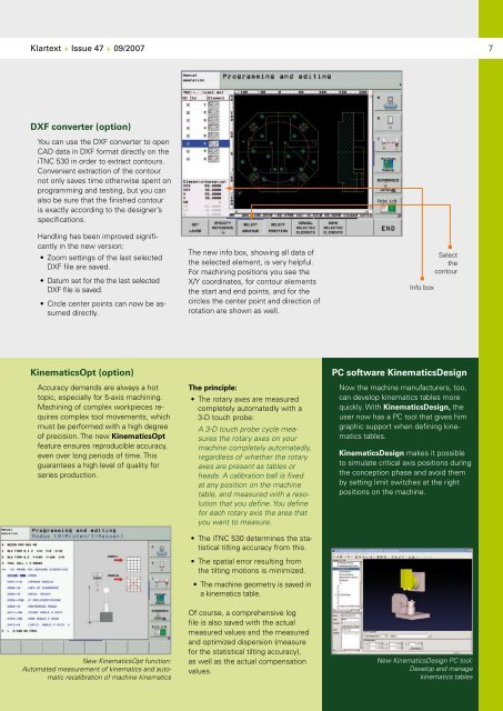
DXF converter (option)<br />
You can use the DXF converter to open<br />
CAD data in DXF format directly on the<br />
i<strong>TNC</strong> 530 in order to extract contours.<br />
Convenient extraction of the contour<br />
not only saves time otherwise spent on<br />
programming and testing, but you can<br />
also be sure that the finished contour<br />
is exactly according to the designer’s<br />
specifications.<br />
Handling has been improved significantly<br />
in the new version:<br />
• Zoom settings of the last selected<br />
DXF file are saved.<br />
• Datum set for the the last selected<br />
DXF file is saved.<br />
• Circle center points can now be assumed<br />
directly.<br />
KinematicsOpt (option)<br />
Accuracy demands are always a hot<br />
topic, especially for 5-axis machining.<br />
Machining of complex workpieces requires<br />
complex tool movements, which<br />
must be performed with a high degree<br />
of precision. The new KinematicsOpt<br />
feature ensures reproducible accuracy,<br />
even over long periods of time. This<br />
guarantees a high level of quality for<br />
series production.<br />
New KinematicsOpt function:<br />
Automated measurement of kinematics and automatic<br />
recalibration of machine kinematics<br />
The new info box, showing all data of<br />
the selected element, is very helpful.<br />
For machining positions you see the<br />
X/Y coordinates, for contour elements<br />
the start and end points, and for the<br />
circles the center point and direction of<br />
rotation are shown as well.<br />
The principle:<br />
• The rotary axes are measured<br />
completely automatedly with a<br />
3-D touch probe:<br />
A 3-D touch probe cycle measures<br />
the rotary axes on your<br />
machine completely automatedly,<br />
regardless of whether the rotary<br />
axes are present as tables or<br />
heads. A calibration ball is fixed<br />
at any position on the machine<br />
table, and measured with a resolution<br />
that you define. You define<br />
for each rotary axis the area that<br />
you want to measure.<br />
• The i<strong>TNC</strong> 530 determines the statistical<br />
tilting accuracy from this.<br />
• The spatial error resulting from<br />
the tilting motions is minimized.<br />
• The machine geometry is saved in<br />
a kinematics table.<br />
Of course, a comprehensive log<br />
file is also saved with the actual<br />
measured values and the measured<br />
and optimized dispersion (measure<br />
for the statistical tilting accuracy),<br />
as well as the actual compensation<br />
values.<br />
Info box<br />
Select<br />
the<br />
contour<br />
PC software KinematicsDesign<br />
Now the machine manufacturers, too,<br />
can develop kinematics tables more<br />
quickly. With KinematicsDesign, the<br />
user now has a PC tool that gives him<br />
graphic support when defining kinematics<br />
tables.<br />
KinematicsDesign makes it possible<br />
to simulate critical axis positions during<br />
the conception phase and avoid them<br />
by setting limit switches at the right<br />
positions on the machine.<br />
New KinematicsDesign PC tool:<br />
Develop and manage<br />
kinematics tables