Klartext 47 - TNC 640 - Heidenhain
Klartext 47 - TNC 640 - Heidenhain
Klartext 47 - TNC 640 - Heidenhain

You also want an ePaper? Increase the reach of your titles
YUMPU automatically turns print PDFs into web optimized ePapers that Google loves.
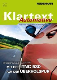
Accuracy<br />
from the<br />
Very First Part<br />
HEIDENHAIN<br />
News from the World of HEIDENHAIN Controls Issue <strong>47</strong> + 9/2007<br />
4<br />
6<br />
12<br />
18<br />
New Innovative<br />
Functions for the<br />
i<strong>TNC</strong> 530<br />
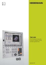
<strong>TNC</strong> 620, the New<br />
Contouring Control<br />
from HEIDENHAIN<br />
MANUALplus 620, the<br />
Contouring Control for<br />
CNC and Cycle Lathes
Editorial<br />
Dear <strong>Klartext</strong> Reader,<br />
The motto for this year’s stand at EMO<br />
is “HEIDENHAIN shows the way to<br />
precision.” Demonstration units and<br />
presentations will show the advantages<br />
of machine tools equipped with linear<br />
encoders.<br />
Real workpieces will give provide tangible<br />
evidence of the differences that<br />
occur on machines with and without<br />
linear encoders.<br />
Of course, once again many product<br />
innovations will be presented. For example,<br />
HEIDENHAIN will in the future<br />
connect its control components using<br />
the purely digital real-time Ethernet bus<br />
HSCI. This makes the entire system<br />
thoroughly diagnosable and more available.<br />
The new <strong>TNC</strong> 620, which was<br />
conceived for the mid-range processing<br />
power segment, and the well-known,<br />
field-proven i<strong>TNC</strong> 530 control to tackle<br />
the high-end applications, with HSCI<br />
and EnDat 2.2 will be featured.<br />
The MANUALplus 620 is a new control:<br />
it was conceived both for CNC and<br />
cycle lathes. The CNC PILOT 4290 lathe<br />
control with B axis makes it possible to<br />
drill, bore and mill in oblique planes.<br />
With its TS 740, HEIDENHAIN will<br />
present a high-accuracy infrared touch<br />
probe for very demanding 3-D measuring<br />
tasks. The new TS 444 is the first<br />
battery-free infrared touch probe system.<br />
So read and enjoy! We are convinced<br />
you’ll be glad you did.<br />
Linear encoders improve the machining accuracy<br />
Page 4<br />
See us at the<br />
EMO 2007<br />
Hannover<br />
Sep. 17-22, 2007<br />
Hall 25<br />
Booth E18
<strong>Klartext</strong> + Issue <strong>47</strong> + 09/2007<br />
With the MANUALplus 620,<br />
HEIDENHAIN presents a new<br />
control, conceived for both<br />
CNC and cycle lathes<br />
Page 18<br />
Production<br />
Publisher<br />
DR. JOHANNES HEIDENHAIN GmbH<br />
Postfach 1260<br />
83292 Traunreut, Germany<br />
Tel: +49/86 69/31- 0<br />
HEIDENHAIN on the Internet:<br />
www.heidenhain.de<br />
The new <strong>TNC</strong> 620 adds a compact<br />
control with digital servo drive<br />
control to the range of products<br />
from HEIDENHAIN<br />
Page 12<br />
Editor<br />
Decisive for the Economic Feasibility: 4<br />
Accuracy from the Very First Part<br />
New Innovative Functions for the i<strong>TNC</strong> 530 6<br />
- New Functions for Plain-Language Programming<br />
- New Functions for smarT.NC<br />
200,000 NC Controls from HEIDENHAIN 11<br />
<strong>TNC</strong> 620 – The New 12<br />
Contouring Control from HEIDENHAIN<br />
Uniformly Digital – New Hardware 14<br />
Concept for HEIDENHAIN Controls<br />
Safety-Related Control Technology 15<br />
for Machine Tools<br />
Innovations for the Infrared Touch Probes 16<br />
MANUALplus 620, The Contouring Control 18<br />
for CNC and Cycle Lathes<br />
CNC PILOT 4290 with B Axis 20<br />
E-Learning for CNC Specialists 22<br />
and for Vocational Training<br />
The TTC Varelerhafen 23<br />
Frank Muthmann<br />
Fax: +49/86 69/31-18 88<br />
E-mail: info@heidenhain.de<br />
<strong>Klartext</strong> on the Internet:<br />
www.heidenhain.de<br />
Layout and Typesetting<br />
Expert Communication GmbH<br />
Richard-Reitzner-Allee 1<br />
85540 Haar, Germany<br />
Tel: +49/89/66 63 75 0<br />
E-mail: info@expert-communication.de<br />
www.expert-communication.de
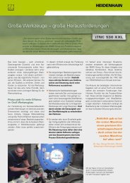
The largest share of thermally-related<br />
inaccuracy on machine tools is produced<br />
in most cases in the feed drives.<br />
High speeds and acceleration levels<br />
heat up the ball screws and cause<br />
them to expand. Without suitable position<br />
measuring technology, this can<br />
lead to positioning errors of up to 100<br />
µm within a few minutes. However,<br />
workpieces with tight tolerances can<br />
only be produced on machine tools<br />
that remain thermally stable despite<br />
very different machining operations.<br />
Position measurement of feed<br />
drives<br />
Small production batches<br />
and single pieces<br />
The position of a linear NC axis can<br />
be measured in principle through the<br />
pitch of the feed screw connected with<br />
a rotary encoder or through a linear<br />
encoder.<br />
In the case of the feed screw/rotary<br />
encoder, the ball screw has a double<br />
function: as a drive system it must<br />
transfer high forces, but for position<br />
specification a high level of accuracy<br />
and repeatability of the screw pitch is<br />
required.<br />
However, the control loop for position<br />
specification includes only the rotary<br />
encoder, which sends signals indicating<br />
the feed screw’s rotational speed<br />
and subdividing each revolution. Wear<br />
and temperature-related changes in the<br />
drive mechanics are not factored into<br />
the position measurement in this case.<br />
The recirculating ball screw heats up when<br />
face milling at 10 m/min. At left is the table,<br />
at right the servo motor.<br />
The thermographic image shows temperatures<br />
of 25 °C (dark blue) to 40 °C (yellow).<br />
Decisive for the Economic Feasibility:<br />
Accuracy from the Very First Part<br />
Positioning errors of the drives become<br />
unavoidable and can have a considerable<br />
influence on the quality of workpieces.<br />
If a linear encoder is used for measurement<br />
of the slide position, the position<br />
control loop includes the complete<br />
feed mechanics. Play and inaccuracies<br />
in the transfer elements of the machine<br />
have no influence in this case on the<br />
accuracy of the position measurement.<br />
Measurement accuracy depends almost<br />
solely on the precision and installation<br />
location of the linear encoder.<br />
Linear encoders from HEIDENHAIN<br />
improve the machining accuracy<br />
Example of machining an<br />
integral component<br />
Typical integral components are machined<br />
on high-performance HSC<br />
machine tools in conjunction with high<br />
feed rates and high cutting speeds. Different<br />
feed rates during roughing and<br />
finishing lead to continually changing<br />
thermal expansion factors of the ball<br />
screws. If the feed drives are operated<br />
without linear encoders, part dimensions<br />
differ for each manufactured<br />
single component in small production<br />
quantities with short door-to-door<br />
times. The danger therefore exists that<br />
thermal expansion will prevent the<br />
specified manufacturing tolerances<br />
from being achieved.
<strong>Klartext</strong> + Issue <strong>47</strong> + 09/2007<br />
How position capture should be<br />
realized on feed axes<br />
Velocity<br />
measurement<br />
Position<br />
measurement<br />
Such sources of errors can be prevented<br />
through the use of linear encoders,<br />
which enable thermal expansion of the<br />
ball screws to be fully compensated.<br />
The test shown in the figures clearly<br />
illustrates the thermal errors of machining<br />
without linear encoders.<br />
A coupling lever from aviation technology<br />
is milled from aluminum to a depth<br />
of 10 mm. After 20 air cycles above the<br />
workpiece, the lower part of the lever<br />
is milled. The thermal drift of the feed<br />
axis is visible by an edge on the side<br />
of the workpiece. If the machine has<br />
linear encoders, then no edge results<br />
in this test.<br />
A reproducible accuracy from the very<br />
first unit is guaranteed!<br />
Effects on mold and die making<br />
Mold and die making for milling places<br />
high demands on the form accuracy.<br />
At the same time, high feed rates are<br />
necessary in order to shorten machining<br />
times. The first and last milling<br />
paths must match, otherwise the time<br />
previously gained would be lost due<br />
to extensive reworking. The example<br />
shows a form machined to represent<br />
the profile of the Watzmann mountain.<br />
In order to visualize the linear deviation<br />
resulting on this mold component from<br />
operation without linear encoders, machining<br />
was deliberately begun in the<br />
middle of the workpiece. Start and end<br />
paths therefore lie side by side, and the<br />
edge clearly shows the thermal drift. If<br />
a machine tool with linear encoders is<br />
used, then the Watzmann profile does<br />
not show this edge.<br />
Coupling lever, processed twice from the same blank form<br />
Without linear encoders (left): Thermal drift is visible by the offset on the edge<br />
With linear encoders (right): No thermal drift visible<br />
Watzmann profile with free-formed surfaces:<br />
machined on the left without linear encoders,<br />
on the right with linear encoders<br />
Conclusion:<br />
Production orders are completed es-<br />
pecially successfully if the machine<br />
tools used feature a high degree of<br />
thermal stability. In this case the feed<br />
axes must achieve the required accuracy<br />
over the complete traverse range<br />
even with strongly varying speeds and<br />
machining forces. These targets can<br />
be met by using linear encoders on<br />
machine tools.<br />
At the HEIDENHAIN stand<br />
in Hall 25, Booth E18, you can<br />
see and feel the effects of such<br />
machining on the actual work-<br />
pieces described in this article.
New Innovative Functions<br />
for the i<strong>TNC</strong> 530<br />
Dynamic Collision Monitoring<br />
The NC software 340 49x-04 for the<br />
i<strong>TNC</strong> 530 includes a series of new<br />
functions for machine manufacturers<br />
and users. These functions make<br />
it even easier to work with the control,<br />
and they also make operation<br />
of the machine more safe.<br />
Dynamic Collision Monitoring<br />
(DCM)<br />
Dynamic Collison Monitoring (DCM)<br />
helps prevent damage to the machine<br />
and workpieces. Although NC<br />
programs created from CAD/CAM<br />
systems avoid collisions between<br />
the tool and workpiece, the machine<br />
components in the work envelope<br />
are not taken into consideration.<br />
This is where HEIDENHAIN comes<br />
into play, and makes the work envelope<br />
defined by the machine manufacturer<br />
visible to the control. The operator<br />
can see machine components<br />
in danger of collision on the screen,<br />
and then move them out of the collision<br />
area. The adaptable settings for<br />
the split screen layout are new. For<br />
example, the program blocks can be<br />
displayed in one window, and the<br />
work envelope in the other window.<br />
If a collision is imminent, the control<br />
interrupts the automated machining.<br />
Adaptive Feed Control<br />
DXF Converter<br />
KinematicsOpt<br />
KinematicsDesign<br />
Adaptive Feed Control (AFC)<br />
Adaptive Feed Control (AFC) optimizes<br />
the contouring feed rate depending on<br />
the performance of the tool spindle and<br />
other process data.<br />
The dynamic line diagram in the status<br />
window is new. It shows how the<br />
contouring feed rate and spindle performance<br />
relate to another.<br />
During the learning<br />
phase, the <strong>TNC</strong> shows<br />
the currently saved<br />
reference power in<br />
a pop-up window. If<br />
required, you can use<br />
a soft key to reset the<br />
reference power measured<br />
up to that point<br />
and restart the learning<br />
process.
<strong>Klartext</strong> + Issue <strong>47</strong> + 09/2007<br />
DXF converter (option)<br />
You can use the DXF converter to open<br />
CAD data in DXF format directly on the<br />
i<strong>TNC</strong> 530 in order to extract contours.<br />
Convenient extraction of the contour<br />
not only saves time otherwise spent on<br />
programming and testing, but you can<br />
also be sure that the finished contour<br />
is exactly according to the designer’s<br />
specifications.<br />
Handling has been improved significantly<br />
in the new version:<br />
• Zoom settings of the last selected<br />
DXF file are saved.<br />
• Datum set for the the last selected<br />
DXF file is saved.<br />
• Circle center points can now be assumed<br />
directly.<br />
KinematicsOpt (option)<br />
Accuracy demands are always a hot<br />
topic, especially for 5-axis machining.<br />
Machining of complex workpieces requires<br />
complex tool movements, which<br />
must be performed with a high degree<br />
of precision. The new KinematicsOpt<br />
feature ensures reproducible accuracy,<br />
even over long periods of time. This<br />
guarantees a high level of quality for<br />
series production.<br />
New KinematicsOpt function:<br />
Automated measurement of kinematics and automatic<br />
recalibration of machine kinematics<br />
The new info box, showing all data of<br />
the selected element, is very helpful.<br />
For machining positions you see the<br />
X/Y coordinates, for contour elements<br />
the start and end points, and for the<br />
circles the center point and direction of<br />
rotation are shown as well.<br />
The principle:<br />
• The rotary axes are measured<br />
completely automatedly with a<br />
3-D touch probe:<br />
A 3-D touch probe cycle measures<br />
the rotary axes on your<br />
machine completely automatedly,<br />
regardless of whether the rotary<br />
axes are present as tables or<br />
heads. A calibration ball is fixed<br />
at any position on the machine<br />
table, and measured with a resolution<br />
that you define. You define<br />
for each rotary axis the area that<br />
you want to measure.<br />
• The i<strong>TNC</strong> 530 determines the statistical<br />
tilting accuracy from this.<br />
• The spatial error resulting from<br />
the tilting motions is minimized.<br />
• The machine geometry is saved in<br />
a kinematics table.<br />
Of course, a comprehensive log<br />
file is also saved with the actual<br />
measured values and the measured<br />
and optimized dispersion (measure<br />
for the statistical tilting accuracy),<br />
as well as the actual compensation<br />
values.<br />
Info box<br />
Select<br />
the<br />
contour<br />
PC software KinematicsDesign<br />
Now the machine manufacturers, too,<br />
can develop kinematics tables more<br />
quickly. With KinematicsDesign, the<br />
user now has a PC tool that gives him<br />
graphic support when defining kinematics<br />
tables.<br />
KinematicsDesign makes it possible<br />
to simulate critical axis positions during<br />
the conception phase and avoid them<br />
by setting limit switches at the right<br />
positions on the machine.<br />
New KinematicsDesign PC tool:<br />
Develop and manage<br />
kinematics tables
Global program settings (option)<br />
User-friendly improvements have been<br />
made to the global program settings<br />
function.<br />
What to do if large, externally created<br />
NC programs need to be modified?<br />
You define coordinate transformations<br />
and settings that have a global effect<br />
and are superimposed on the selected<br />
part program. This way the actual NC<br />
program does not need to be changed.<br />
Along with datum shifts, rotations and<br />
mirror images, axes can be switched or<br />
disabled and handwheel superimpositions<br />
can be set.<br />
3-D basic rotation, machinespecific<br />
(upgrade function)<br />
This function can be used to correct<br />
any workpiece misalignment in three<br />
dimensions (3-D set-up compensation).<br />
Prerequisites:<br />
• Your machine must have at least<br />
two rotary axes.<br />
• Your machine manufacturer must<br />
adapt this function specifically to<br />
your machine.<br />
A new feature is the activation of the<br />
virtual axis (VT)<br />
For example, if you want to run an<br />
entire part program with a constant<br />
oversize, you can use the handwheel<br />
to move the tool in the currently active<br />
tool axis direction (if Tool Center Point<br />
Management (TCPM) is active).<br />
Use the HR 420 handwheel: then you<br />
can select the virtual axis (VT) directly<br />
via the handwheel soft keys. You can<br />
see the value of the distance moved<br />
in the virtual axis direction in the handwheel’s<br />
display.<br />
New function:<br />
Generation of service files<br />
Good error logs are often needed in<br />
case of errors or uncertainties. Now<br />
there is a function that collects all<br />
important data in a ZIP file.<br />
The ZIP file contains:<br />
• the active NC program<br />
• the tool table TOOL.T<br />
• any active datum tables<br />
• important system files<br />
Download the ZIP file through one<br />
of the data interfaces, and e-mail it<br />
to your machine manufacturer or the<br />
HEIDENHAIN service department.<br />
Rapid assistance will be available that<br />
much sooner.<br />
New conversational languages<br />
(option)<br />
Starting immediately, Turkish and<br />
Romanian are available as conversational<br />
languages.<br />
For handwheels without integrated<br />
position display: here you select the<br />
virtual axis with a machine key defined<br />
by the machine manufacturer. The distance<br />
moved is shown in a separate<br />
position display (and also in the global<br />
program settings form). The value remains<br />
stored until you change the tool<br />
or switch the function off.<br />
The global program settings come into<br />
play especially in large-scale mold making.<br />
New file management<br />
Are you already familiar with the file<br />
management in smarT.NC, which<br />
can now be operated entirely with<br />
the mouse, as well as by soft key?<br />
File management for conversational<br />
programming now works identically.<br />
Further highlights:<br />
• Files can now be sorted by name,<br />
type, size, date of change and<br />
status.<br />
• Favorites can be managed.<br />
• Files are selected when the first<br />
letter of the file name is entered<br />
on the keyboard.<br />
• The display of file information can<br />
be configured now.<br />
• The date format can be configured<br />
now.
<strong>Klartext</strong> + Issue <strong>47</strong> + 09/2007<br />
Display of values in the virtual axis (VT)<br />
New Functions for Plain-Language Programming<br />
New: Pattern definition<br />
The point-pattern generator function<br />
already known from smarT.NC is now<br />
also available for plain-language programming.<br />
New PATTERN DEF function:<br />
Definition of the machining pattern:<br />
• Points (up to 9 individual positions)<br />
• Row<br />
• Frame<br />
• Area<br />
• Circular arc<br />
• Full circle<br />
The machining patterns defined in this<br />
way can be called with the familiar<br />
CYCL CALL PATTERN function.<br />
New: Globally effective cycle<br />
parameters<br />
GLOBAL DEF cycles: You can define a<br />
wide variety of cycle parameters at the<br />
beginning of the program with global<br />
effect.<br />
The following groups are available:<br />
• General cycle parameters such as<br />
safety clearance or retraction feed<br />
rate<br />
• Drilling-specific cycle parameters,<br />
such as dwell times<br />
• Milling-specific cycle parameters,<br />
such as the plunging behavior<br />
• Touch-probe-specific cycle parameters,<br />
such as clearance height<br />
In the cycle definition you simply link to<br />
the defined values via soft key.<br />
The <strong>TNC</strong> then enters the word PREDEF<br />
(for predefined) in the cycle definition.<br />
Any change in the GLOBAL DEF cycle<br />
affects all cycles that refer to the PRE-<br />
DEF entry in the respective GLOBAL<br />
DEF cycle.<br />
Hardware requirements for<br />
the new 340 49x-04 software<br />
for the i<strong>TNC</strong> 530<br />
• MC 422 B or C main computer<br />
• 512 MB RAM<br />
File functions<br />
With the FILE FUNCTION feature you<br />
can copy, move and delete files from<br />
within the part program. This enables<br />
you, for example, to copy and start part<br />
programs that you have saved on an<br />
external drive.<br />
New: Machining rectangular<br />
and circular studs<br />
Rectangular and circular studs can now<br />
be machined even more easily with the<br />
new Cycles 256 and 257. The constant<br />
cut distribution is particularly helpful<br />
when the difference between the dimensions<br />
of the blank and the finished<br />
part is greater than the tool radius. Of<br />
course, the distribution of cuts can be<br />
modified by an overlap factor.<br />
The new cycles are structured similarly<br />
to the already existing milling cycles<br />
251 and 254.
10<br />
New smarT.NC Functions<br />
New datum shift<br />
Being able to shift the datum solely<br />
via datum tables is now a thing of the<br />
past. You can now also define the shifts<br />
for specific axes in a form. And resetting<br />
is even easier: just press a soft<br />
key, and it’s done!<br />
New: Machining rectangular<br />
and circular studs<br />
The new Cycles 256 and 257 for<br />
plain-language programming are<br />
mirrored in the smarT.NC operating<br />
mode, with machining units 256<br />
and 257.<br />
Inline pattern definitions<br />
revised<br />
Being able to define machining patterns<br />
without a pattern generator: that is<br />
new, and is done directly in the overview<br />
form of a machining unit. Available<br />
patterns:<br />
• Points (up to 9 individual positions)<br />
• Row<br />
• Frame<br />
• Area<br />
• Circular arc<br />
• Full circle<br />
smarT.NC<br />
operating<br />
mode<br />
Datum shifts<br />
Rectangular and circular studs<br />
Inline pattern definitions<br />
Machining strategy<br />
Program end unit<br />
Loading values from previous<br />
units<br />
Repetitions occur frequently, and machining<br />
units often only differ in small<br />
details. For example, when different<br />
tools or oversizes are used for roughing<br />
and finishing definitions.<br />
This is now made quite simple with<br />
smarT.NC: you can use the values<br />
defined in the earlier machining unit as<br />
default values for the new machining<br />
unit (in the same smarT.NC program).<br />
This saves you much programming<br />
time.<br />
New: Setting the number of<br />
probing points for a circle<br />
Measuring circles as previously with<br />
4 probing points, or with just 3?<br />
You have the choice in touch-probe<br />
machining units 412, 413, 421 and 422.<br />
New: Defining a machining<br />
strategy for clearing<br />
How should the <strong>TNC</strong> move the tool<br />
during clearing?<br />
Choose in machining unit 22:<br />
• Retracing the entire contour<br />
The <strong>TNC</strong> moves at constant height<br />
to the areas to be cleared without<br />
removing the tool from the finished<br />
part contour. This strategy works<br />
well when the distance between<br />
the areas to be cleared is small<br />
and the fine roughing tool is large<br />
enough to machine the remaining<br />
material in one step.
<strong>Klartext</strong> + Issue <strong>47</strong> + 09/2007 11<br />
• or machining individual areas<br />
separately<br />
After fine roughing each area to be<br />
cleared, the <strong>TNC</strong> moves the tool at<br />
rapid traverse to the safety clearance.<br />
This strategy is helpful when<br />
there is a large distance between<br />
the areas.<br />
Fast retraction during tapping<br />
There are still possibilities for reducing<br />
machining time: for example, you can<br />
retract at a shaft speed greater by a<br />
factor X from a drill hole. You specify<br />
this factor in machining unit 209 for<br />
tapping.<br />
Also new in smarT.NC:<br />
KinematicsOpt (Option)<br />
This new function, the measurement<br />
of machine kinematics, already described<br />
for plain-language programming,<br />
is now available in smarT.NC as<br />
well, via machining units 450 and 451.<br />
New: Program end unit<br />
The following settings can be made in<br />
the program end unit:<br />
• Definition of M functions, e.g. M5,<br />
M30<br />
• Approach to a safe position in the<br />
tool axis<br />
(either in the workpiece or machine<br />
coordinate system)<br />
• Approach to a safe position in the<br />
working plane<br />
(either in the workpiece or machine<br />
coordinate system)<br />
200,000 NC Controls from<br />
HEIDENHAIN<br />
In the middle of 2007 HEIDENHAIN<br />
shipped its 200,000th NC control,<br />
and celebrated a new record in its<br />
30-year history of success. With<br />
over 30,000 units, the i<strong>TNC</strong> 530 has<br />
succeeded the <strong>TNC</strong> 426 as HEIDEN-<br />
HAIN’s most successful of over 50<br />
models. Over 10,000 units of this<br />
model are expected to ship from<br />
Traunreut in 2007—numbers that<br />
speak for its great acceptance in the<br />
NC control market.<br />
These <strong>TNC</strong> controls have their roots<br />
in the workshop, where they banished<br />
machinists’ reluctance toward<br />
the new technology. Today, their<br />
user-friendly dialog guidance ensures<br />
HEIDENHAIN a high market share in<br />
applications that require shop-floor<br />
programming.<br />
Plain-language, conversational programming<br />
has won its place in the<br />
metalworking industry with HEIDEN-<br />
HAIN controls guiding the user with<br />
questions and prompts and automatically<br />
generating the program. Since<br />
2004, the “smarT.NC” operating mode<br />
has offered even more convenience<br />
with straightforward fillable forms, interactive<br />
graphics and quickly understood<br />
user aids.<br />
HEIDENHAIN controls are widely<br />
used on machines capable of manufacturing<br />
parts of high quality. At the<br />
high end—on machining centers and<br />
complex milling machine for 5-axis<br />
machining—the i<strong>TNC</strong> 530 stands for<br />
short machining times, high contour accuracy<br />
and best surface quality. In the<br />
mid-range, the <strong>TNC</strong> 320 provides precision<br />
and efficiency in manufacturing<br />
on machines with up to four controlled<br />
axes. The <strong>TNC</strong> 124, a well-proven<br />
straight-cut control for simple machine<br />
tools, meets customers’ needs for less<br />
demanding control tasks. Controls for<br />
lathes such as the MANUALplus 4110<br />
complete the product range.
1<br />
The <strong>TNC</strong> 620 – The New Contouring<br />
Control from HEIDENHAIN<br />
The new <strong>TNC</strong> 620 adds a compact con-<br />
trol with digital servo drive control to<br />
the range of products from HEIDEN-<br />
HAIN. HEIDENHAIN already introduced<br />
the <strong>TNC</strong> 320, an analog control for simple<br />
3-axis machines, at the EMO 2005,<br />
and it has been proving itself in daily<br />
operation ever since. Both controls are<br />
based on a new, trend-setting software<br />
concept from HEIDENHAIN, and use<br />
the same software platform.<br />
Keep learning instead<br />
of re-learning<br />
HEIDENHAIN controls undergo continuous<br />
improvement, but the basic<br />
operational technique remains the<br />
same. The motto “keep learning instead<br />
of re-learning” is as valid today<br />
as it has always been. This basic premise<br />
was naturally taken into account<br />
for the <strong>TNC</strong> 620: an experienced <strong>TNC</strong><br />
programmer will have absolutely no<br />
problems with the <strong>TNC</strong> 620.<br />
Thanks to the workshop oriented programming<br />
style with helpful dialogs<br />
and graphic support, novices will quickly<br />
feel at home when using the new<br />
control. The clear structure of the soft<br />
keys constantly gives you an overview<br />
of the necessary functions, so that<br />
you can find them immediately. The<br />
keys for initiating typical <strong>TNC</strong> dialogs<br />
are included on the compact keyboard,<br />
so that you can quickly access all <strong>TNC</strong><br />
functions. In addition, the machine<br />
manufacturer can make machine-specific<br />
functions available in the vertical<br />
soft-key row.<br />
Workshop oriented, compact<br />
and trend-settingly digital<br />
Cycles simplify program<br />
creation<br />
The <strong>TNC</strong> 620 features numerous cycles<br />
designed for most machining tasks that<br />
occur on the shop floor. Along with the<br />
machining cycles for drilling, tapping<br />
(with or without floating tap holder),<br />
thread cutting, reaming, and boring,<br />
there are also cycles for hole patterns<br />
(circular and linear). Milling cycles include<br />
facing of flat surfaces, as well as<br />
roughing and finishing pockets, slots<br />
and studs.<br />
Touch-probe cycles, which can easily<br />
be integrated into the machining<br />
program, are available for automatic<br />
measurement and inspection of workpieces.<br />
The <strong>TNC</strong> 620 provides meaningful<br />
support graphics and dialog texts<br />
when the machine operator enters<br />
information for machining or touchprobe<br />
cycles.<br />
When creating workshop-oriented programs<br />
using the tried-and-true conversational<br />
programming language from<br />
HEIDENHAIN, the programming graphics<br />
interactively show step-by-step<br />
what is currently being programmed.<br />
This is especially helpful when using<br />
the powerful free-contour programming<br />
feature to create parts not dimensioned<br />
for NC.<br />
Knowing ahead of time—<br />
thanks to sophisticated<br />
graphics<br />
After completion of an NC program,<br />
the test run graphics can give a realistic<br />
impression of the finished part<br />
before machining begins. The <strong>TNC</strong> also<br />
performs an internal test run to check<br />
the NC program for logical errors, even
<strong>Klartext</strong> + Issue <strong>47</strong> + 09/2007 1<br />
before the workpiece is placed in the<br />
machine. This makes it easy to avoid<br />
downtimes. Tips about the cause of error,<br />
as well as possibilities for troubleshooting,<br />
simplify the search for errors.<br />
Simple handling of complex<br />
operations<br />
The <strong>TNC</strong> 620 is equipped for handling<br />
very complicated tasks, even those<br />
that also include the use of swivel and<br />
rotary axes. For example, the working<br />
plane can be tilted around one or more<br />
rotary axes. The machining program is<br />
then simply created in the main plane<br />
(usually X/Y). Special cycles are even<br />
available for machining contours, slots<br />
or ridges on cylinders as if they were in<br />
just two axes.<br />
The <strong>TNC</strong> 620 also features special functions<br />
for simultaneous machining with<br />
up to five axes: dynamic advance calculation<br />
of the contour, algorithms for<br />
jerk limiting, and intelligent path control<br />
fulfill the high demands placed on the<br />
surface quality of the workpiece.<br />
Select your features<br />
You can determine the scope of your<br />
<strong>TNC</strong> 620’s functions to meet your<br />
needs and desires. You select various<br />
options to configure your control in a<br />
manner useful to you, and for what<br />
it will need to do in daily operation.<br />
But of course this configuration is not<br />
carved in stone. If it turns out in the<br />
future that you need a function not<br />
initially chosen, you can have your machine<br />
tool builder activate the function<br />
for you.<br />
Hardware design: compact and<br />
modern<br />
In the past, the MC main computer and<br />
CC controller unit of digital HEIDEN-<br />
HAIN controls were always installed<br />
in the electrical cabinet. Now the main<br />
computer is housed inside the operating<br />
panel, directly behind the <strong>TNC</strong> keyboard<br />
and the large, clear, 15-inch TFT<br />
flat-panel display with XGA resolution<br />
(1024 x 768 pixels). Complicated wiring<br />
is now a thing of the past.<br />
The CC controller unit is still in the<br />
electrical cabinet, and is connected<br />
with the power stages via the wellproven<br />
PWM interface.<br />
HSCI – the new modular<br />
hardware concept<br />
The new hardware concept of the<br />
<strong>TNC</strong> 620 also ensures that connecting<br />
the individual components of the control<br />
will be child’s play in the future.<br />
The main computer, controller unit, and<br />
other components of the HEIDENHAIN<br />
control system feature a new, powerful<br />
interface: HSCI. The outstanding properties<br />
of the uniformly digital design of<br />
the <strong>TNC</strong> 620 entire system guarantee<br />
not just very high accuracy and surface<br />
quality, but also rapid traverse speeds<br />
as well as high availability of the entire<br />
system (see page 14 for more information).<br />
And what’s inside? Plenty of<br />
processing power and memory<br />
space!<br />
The <strong>TNC</strong> 620 is equipped with a powerful<br />
Intel processor with a clock frequency<br />
of 400 MHz. In addition, the 512 MB<br />
of RAM ensure that complex graphic<br />
simulations are processed quickly.<br />
A CompactFlash memory card is used<br />
for both NC and PLC programs. The<br />
memory card is immune to mechanical<br />
shock, thereby offering optimum safety<br />
for your data.<br />
The <strong>TNC</strong> 620 is a reliable partner in<br />
the workshop when it comes to data<br />
transmission. This is taken care of by<br />
the Fast Ethernet interface, integrated<br />
as a standard feature, which makes it<br />
possible to connect the <strong>TNC</strong> to your<br />
company network with very little effort.<br />
Input and pointing devices, as well as<br />
external media (such as USB sticks or<br />
external hard drives), are connected to<br />
the <strong>TNC</strong> 620 via the USB port.<br />
The <strong>TNC</strong> 620 is offered with three controlled<br />
axes and a controlled spindle,<br />
and as an option, two more controlled<br />
axes can be added. (Software options<br />
can be used to adapt the scope of<br />
function of the NC software to the<br />
respective needs and applications.)
1<br />
The hardware design of the future:<br />
Uniformly digital connection of the various<br />
control components<br />
HSCI: HEIDENHAIN<br />
Serial Controller Interface<br />
HSCI<br />
Uniformly Digital – The New<br />
Hardware Design for Controls<br />
from HEIDENHAIN<br />
Uniformly digital is more than just<br />
a buzzword: all components are<br />
connected to each other via purely<br />
digital interfaces. The control components<br />
are connected via HSCI<br />
(HEIDENHAIN Serial Controller Interface),<br />
the new real-time protocol<br />
from HEIDENHAIN for Fast Ethernet,<br />
and the encoders are connected via<br />
EnDat 2.2, the bidirectional interface<br />
from HEIDENHAIN.<br />
Both the machine manufacturer and<br />
the end user profit from the advantages:<br />
the entire system becomes<br />
less susceptible to noise, is thoroughly<br />
diagnosable, and so ensures<br />
a high degree of availability.<br />
The previous, proven<br />
hardware design<br />
The MC main computer and CC<br />
controller unit are both contained in<br />
the electrical cabinet. The operating<br />
panel only includes the screen and<br />
keyboard. The components of the<br />
operating panel are connected to<br />
the MC main computer via several<br />
cables.<br />
The new hardware design<br />
The MC and CC are connected via a<br />
real-time Ethernet cable, specifically<br />
a 100BaseT Ethernet Physical Layer<br />
device. The protocol was developed by<br />
HEIDENHAIN, and carries the designation<br />
HSCI. Together with the purely<br />
digital EnDat 2.2 encoder interface,<br />
there is a uniformly digital design from<br />
the main computer to the encoder.<br />
The main advantages of this new<br />
design:<br />
• Simpler wiring<br />
• Simpler commissioning<br />
• Extensive possibilities for diagnostics<br />
• Improved noise immunity<br />
This new technology ensures highest<br />
accuracy and surface quality at high<br />
traverse speeds.
<strong>Klartext</strong> + Issue <strong>47</strong> + 09/2007 1<br />
Safety is becoming increasingly important<br />
in machine and plant construction.<br />
These measures mainly serve to protect<br />
human beings, but material assets<br />
and the environment are also receiving<br />
more consideration.<br />
Safety-Related Control<br />
Technology for<br />
Machine Tools<br />
The goal of functional safety is to minimize<br />
or at least reduce the risks that<br />
can occur during normal or impaired<br />
operation of machines or facilities.<br />
The first step of this is achieved with<br />
redundant systems. For example, axes<br />
that are moved in safety-oriented applications<br />
require redundant position<br />
information in order to perform the<br />
corresponding safety functions.<br />
Basic principle<br />
The controls and position encoders<br />
from HEIDENHAIN with functional<br />
safety meet safety integrity level 2<br />
(SIL 2) as per the IEC 61 508 standard,<br />
as well as the performance level “d”<br />
as per ISO 13 849-1 (which replaced<br />
ISO 954-1). These standards describe<br />
the assessment of safety-oriented<br />
systems, for example based on the<br />
failure probabilities of integrated components<br />
and subsystems. This modular<br />
approach helps manufacturers of<br />
safety-oriented systems to implement<br />
their systems, because they can begin<br />
with prequalified subsystems. Position<br />
encoders with functional safety and the<br />
i<strong>TNC</strong> 530 with HSCI control accommodate<br />
this concept.<br />
Functional safety on machine<br />
tools<br />
HEIDENHAIN is planning on offering<br />
HSCI controls with functional safety<br />
starting in the middle of 2008. Two<br />
redundant safety channels that work<br />
independently of each other are the<br />
foundation for controls with functional<br />
safety. All safety-relevant signals are<br />
captured, processed and output via<br />
two channels. Errors are detected by<br />
mutual comparison of the states and<br />
data in the two channels. This way, the<br />
occurrence of just one error in the control<br />
does not lead to the safety functions<br />
being incapacitated.<br />
The goal is to make actions by the<br />
machine operator at machining centers<br />
possible during automated production<br />
runs, even when protective measures<br />
are not in effect (such as protective<br />
doors being open), without danger to<br />
the operator:<br />
• Setup<br />
• Manual intervention<br />
• Process monitoring<br />
Safety-related operating modes<br />
HEIDENHAIN controls with functional<br />
safety offer four safety-related operating<br />
modes as per the EN 12 417 standard<br />
(Machine Tools–Safety–Machining<br />
Centers).<br />
Operating mode 1<br />
Automated or production mode<br />
• Operation only with closed<br />
protective door<br />
• No machine motion possible if<br />
protective door is open<br />
Operating mode 2<br />
Set-up mode<br />
• Operation with open protective<br />
doors<br />
• Axis motions of 2 m/min at most<br />
• Spindle stop within 2 revolutions<br />
• Only one axis can be moved at a<br />
time (no interpolating motions)<br />
• Spindle rotation only possible<br />
with permissive button<br />
Operating mode 3<br />
Manual intervention<br />
• Operation with open protective<br />
doors<br />
• Axis motions of 5 m/min at most<br />
• Spindle stop within 5 revolutions<br />
• More than one axis can be moved<br />
at a time (interpolating motions)<br />
• Spindle rotation only possible with<br />
permissive button<br />
Operating mode 4<br />
Advanced manual intervention,<br />
process monitoring<br />
• Operation with open protective<br />
doors<br />
• Axis motions of 5 m/min at most<br />
• Spindle stop within 5 revolutions<br />
• More than one axis can be moved<br />
at a time (interpolating motions)<br />
• Permissive button must only be<br />
pressed to start spindle rotation
1<br />
Innovations for the Infrared<br />
Touch Probes<br />
The TS 740 and TS 444 workpiece touch<br />
probes are two newly developed products<br />
from HEIDENHAIN.<br />
TS 740 –<br />
The high-accuracy touch probe<br />
The TS 740 is the right touch probe for<br />
measurement tasks with especially<br />
high demands regarding probing accuracy<br />
and repeatability. In spite of its<br />
very low probing forces, the TS 740<br />
does not generate an uncontrolled<br />
trigger signal at high accelerations and<br />
rapid probing.<br />
Probing process:<br />
Contact with a workpiece deflects the<br />
stylus, applying a force to the pressure<br />
elements, which are the core of our<br />
newly developed sensor. The difference<br />
in forces is calculated by the electronics,<br />
and the trigger signal is generated.<br />
Touch probe Probe accuracy Probe repeatability<br />
(repeated probing from<br />
one direction)<br />
TS 440 / TS <strong>640</strong> ≤ ± 5 µm<br />
(when using a standard<br />
stylus)<br />
2 σ ≤ 1 µm<br />
at a probing velocity<br />
of 3 m/min<br />
TS 740 ≤ ± 1 µm 2 σ ≤ 0.25 µm<br />
at a probing velocity<br />
of 0.25 m/min<br />
TS 740<br />
Very accurate<br />
TS 444<br />
No batteries required<br />
TS <strong>640</strong> and TS 440<br />
Tried and true
<strong>Klartext</strong> + Issue <strong>47</strong> + 09/2007 1<br />
HEIDENHAIN TS touch probes<br />
A frequent requirement is the reduction<br />
of setup times. Use our workpiece<br />
touch probes to perform setup, measuring<br />
and inspection functions directly<br />
on the machine tool.<br />
TS 444 –<br />
The touch probe without<br />
batteries<br />
The TS 444 is an innovative and<br />
smart alternative to touch probes<br />
with batteries. Handling, storage and<br />
disposal of batteries is completely<br />
done away with. The only requirement<br />
is the supply of compressed air<br />
through the spindle.<br />
The action of cleaning the workpiece<br />
position to be measured simultaneously<br />
charges the touch probe.<br />
The principle behind the energy<br />
supply:<br />
Compressed air is pushed through<br />
the taper shank into the touch probe<br />
in order to clean the measurement<br />
point before it is probed. A turbine<br />
wheel is driven there. Changes in<br />
the magnetic field generate electrical<br />
energy, which is stored in highpower<br />
capacitors. The exit air is used<br />
for cleaning the probing point. The<br />
compressed air does not need to be<br />
specially cleaned.<br />
The charging time varies depending<br />
on the pressure: The higher the<br />
pressure, the shorter is the charging<br />
time. In order to ensure that charging<br />
takes place within a reasonable<br />
time, the supply pressure should be<br />
at least 5 bars.<br />
For example, at 5.5 bars it takes<br />
around 3 seconds to completely<br />
charge a touch probe. This suffices<br />
for a two-minute measuring cycle.<br />
With touch probes from HEIDENHAIN<br />
you can:<br />
• measure workpieces,<br />
• align workpieces,<br />
• set datums,<br />
• and digitize 3-D forms.<br />
HEIDENHAIN offers touch probes that<br />
transmit the trigger signal either by<br />
cable or by infrared transmission.<br />
TS <strong>640</strong> and TS 440 –<br />
The tried and true touch probes<br />
Our well-proven TS <strong>640</strong> and TS 440<br />
touch probes also have new features.<br />
New:<br />
Longer operating time<br />
We were able to more than double the<br />
operating time for each set of batteries.<br />
By revising the electronics, we were<br />
able to increase the operating times<br />
to about 800 hours for the TS <strong>640</strong>, and<br />
200 hours for the TS 440.<br />
Example:<br />
If a touch probe is active 5% of the<br />
operating time, the batteries must be<br />
exchanged after three years on the<br />
TS <strong>640</strong>, and after nine months on the<br />
TS 440 (3-shift operation, 220 workdays/year,<br />
lithium batteries).<br />
New:<br />
Different possible types of batteries<br />
Alkaline batteries or rechargeable batteries<br />
can now be used as well. Please<br />
keep in mind that the lifetime of highquality<br />
lithium batteries is somewhat<br />
longer.<br />
New:<br />
Optical indicators<br />
Knowledge at a glance: the operator<br />
can now see if the touch probe is<br />
switched on or off. The new indicators<br />
also signalize a deflection of the stylus.
1<br />
MANUALplus 620, the<br />
Contouring Control for CNC<br />
and Cycle Lathes<br />
For years now the MANUALplus 4110<br />
has proven itself on action-oriented<br />
lathes. HEIDENHAIN now introduces<br />
a much improved version of the<br />
MANUALplus. The MANUALplus 620<br />
features improved cycle programming,<br />
and also the brand new smartTurn<br />
programming mode of operation. This<br />
is HEIDENHAIN’s newest control: conceived<br />
both for CNC and cycle lathes.<br />
MANUALplus 620, the control<br />
for CNC and cycle lathes<br />
The MANUALplus 620 is designed for<br />
lathes with spindle, one slide (X and<br />
Z axis), C axis or positionable spindle<br />
and driven tool. It is suited for horizontal<br />
and vertical lathes with simple<br />
tool holders or with tool turrets. Cycle<br />
lathes are usually used for smaller<br />
and mid-size production batches. The<br />
operator of a MANUALplus 620 profits<br />
from the quickly learned cycle programming,<br />
with which workpieces can be<br />
machined quickly and efficiently. And<br />
when requirements increase and you<br />
machine complex tasks with your lathe,<br />
you then create your NC programs<br />
with the new smartTurn programming<br />
mode. The smartTurn programming<br />
mode of operation is the basis for NC<br />
programming on CNC lathes.<br />
This new type of NC programming is<br />
also mastered quickly, since the machinist<br />
does not have to deal with G<br />
or M functions, or with structuring a<br />
machining block. smartTurn uses the<br />
easy-to-learn form entry method of<br />
programming.<br />
Cycle machining<br />
The writing and testing of a “real”<br />
NC program, with G and M functions,<br />
takes too much time for small and<br />
mid-size production batches. The cycle<br />
programming of the MANUALplus is<br />
the ideal solution here, since a cycle is<br />
a pre-programmed machining step, and<br />
therefore only requires few entries.<br />
The machinist can concentrate on<br />
the machining of his workpiece. He<br />
determines the tool for the machining<br />
step, selects the cycle, defines the<br />
required parameters, monitors machining<br />
with the graphic simulation function,<br />
and performs the cycle. This way,<br />
in an action-oriented manner, the first<br />
workpiece and the cycle program are<br />
created at the same time. This cycle<br />
program is then saved. The machinist<br />
can now let the program run automatically,<br />
and each additional part machined<br />
saves time and cost.<br />
You define simple lathe and milling<br />
contours directly in the cycle on the<br />
MANUALplus. And what happens if the<br />
contours become more complex? No<br />
problem! Even complex workpieces<br />
can be described quickly and without<br />
additional calculations when using ICP<br />
contour programming.<br />
The screen:<br />
clearly structured and<br />
user-friendly<br />
smartTurn - the new<br />
programming mode of<br />
operation<br />
The operating panel:<br />
few keys,<br />
identifiable functions<br />
Has the safety clearance been correctly<br />
entered, is the speed limit taken into<br />
account, how are oversizes defined?<br />
All this needs not only be considered<br />
by the beginner, but also by the experienced<br />
NC programmer when creating<br />
conventional DIN/ISO programs.<br />
smartTurn makes many things much<br />
easier: the working block known as a<br />
unit plays the central role in smartTurn<br />
programs. A unit describes a machining<br />
step completely and unambiguously.<br />
The unit includes the tool call, the<br />
technology data, the cycle call, the<br />
approach and departure strategies,<br />
as well as global data, such as safety<br />
clearance, etc. All these parameters<br />
are summarized in one form—simply<br />
and clearly.<br />
For simple operations, you need only<br />
enter a few parameters. You use<br />
smartTurn to define such a machining<br />
step quickly in a single overview window.<br />
If required you can define additional<br />
machining options. These options are<br />
available in subforms in which, with a<br />
few additional keystrokes, you can enter<br />
the data for machining options.<br />
The principle of smartTurn gives you<br />
the reassurance that the working block<br />
is defined correctly and completely. In<br />
the NC program, smartTurn lists the<br />
DIN PLUS commands of the unit. This<br />
not only gives you an overview of all<br />
working-block details, but you also have<br />
a clearly legible and well-structured NC<br />
program.
<strong>Klartext</strong> + Issue <strong>47</strong> + 09/2007 1<br />
Describing contours with ICP<br />
You describe workpieces or contours<br />
with the interactive graphics of the ICP<br />
contour editor. You create the contour<br />
by entering the elements step-by-step.<br />
When selecting the contour elements,<br />
you already specify the direction of the<br />
line or the direction of rotation of the<br />
circular arc. This way the MANUALplus<br />
needs very little information about the<br />
contour element. The MANUALplus<br />
calculates missing coordinates, intersections,<br />
circle center points, etc. In most<br />
cases you can describe the workpiece<br />
Contour follow-up:<br />
Another highlight of the MANUALplus<br />
620 is the contour follow-up feature.<br />
If you define the workpiece blank<br />
at the beginning of your smartTurn<br />
program, the control then computes<br />
the new blank for each following cycle.<br />
The machining cycles are adapted automatically<br />
to the current workpiece<br />
blank. They are so intelligent as to<br />
avoid air cuts and to optimize approach<br />
paths, even if the workpiece material<br />
has been previously removed.<br />
Unit selection:<br />
smartTurn also provides special machining<br />
units to go along with those for<br />
turning, drilling and milling machining.<br />
You define global program parameters,<br />
such as oversizes, safety clearances,<br />
coolants, etc., in the start unit. smart-<br />
Turn then transfers these parameters<br />
to the other units.<br />
with the dimensions given in the production<br />
drawing. If there are multiple<br />
solutions, ICP displays the mathematically<br />
possible variants from which you<br />
can select the correct solution.<br />
Importing DXF:<br />
It’s even easier when the workpiece<br />
drawing is already in DXF format, since<br />
with ICP you can import contours available<br />
in DXF format. Not only does this<br />
save time otherwise spent on testing,<br />
but you can also be sure that the finished<br />
contour is exactly according to<br />
the designer’s specifications.<br />
You can use the smartTurn units to<br />
realize the entire lathe machining operation,<br />
as well as drilling and milling<br />
operations with the C axis. However,<br />
if you want to control special machine<br />
components or use variable programming,<br />
then DIN PLUS programming is<br />
the answer. You use DIN PLUS to realize<br />
functions that are not provided by<br />
smartTurn. A significant advantage of<br />
the MANUALplus 620 is that it enables<br />
you to switch between the smartTurn<br />
and DIN PLUS programming modes<br />
within an NC program.<br />
Unit as form:<br />
Unit as NC program:<br />
The tool and technology<br />
database<br />
Tried-and-true features of the<br />
MANUALplus include the saving of<br />
tool and cutting data, as well as simple<br />
determination of setting dimensions.<br />
The tool database of the MANUALplus<br />
620 not only provides greater<br />
capacities and easily understood dialogs<br />
for data entry, but the MANUALplus<br />
620 also supports placement of<br />
tools in the turret.<br />
If you want to change the tool assignment<br />
or the tools in the turret, you can<br />
additionally display the tools currently<br />
in the turret in the upper window, and<br />
the entries of the tool database in the<br />
lower window. Now you need only<br />
select the turret pocket and choose<br />
the correct tool from the database.<br />
You can transfer the tool data to the<br />
turret assignment entry with a simple<br />
keystroke.<br />
With the MANUALplus 620, you also<br />
need enter the cutting data only once.<br />
The technology database saves the<br />
cutting data according to the criteria<br />
of workpiece material, cutting material<br />
and machining mode. Thanks to this<br />
three-dimensional table, the control<br />
always knows the appropriate feed<br />
rate and the correct cutting speed.<br />
The MANUALplus 620 determines<br />
the machining mode from the cycle<br />
or with smartTurn from the unit. The<br />
cutting material is defined in the tool<br />
description. You need only define the<br />
workpiece material at the beginning<br />
of the cycle program or the smartTurn<br />
program, and the technology database<br />
will propose the correct values for your<br />
machining operation. You can use the<br />
suggested cutting parameters or adjust<br />
them if required.
0<br />
CNC PILOT 4290 with B Axis<br />
At the EMO 2007 HEIDENHAIN will present the CNC PILOT 4290 with<br />
B axis for the first time. The B axis makes it possible to drill, bore and<br />
mill in oblique planes. But lathe machining also profits significantly<br />
from the B axis: by tilting the axis and rotating the tool you can bring<br />
it into positions that enable you to use a single tool to machine in<br />
the longitudinal and transverse directions on the main and opposing<br />
spindles.<br />
The CNC PILOT 4290<br />
The CNC PILOT 4290 lathe control was<br />
conceived both for compact and complex<br />
CNC lathes. The control can be<br />
used for machines with up to six slides,<br />
four spindles, and two C axes (up to<br />
a total of 12 control loops). You do not<br />
just profit from the flexibility of the<br />
control, but the programming itself<br />
is incredibly easy, even for complex<br />
machines with multiple slides.<br />
When creating the program with TURN<br />
PLUS, you describe the workpiece<br />
with interactive graphics, and<br />
then generate the NC program<br />
automatically with a keystroke.<br />
The automatic working plan<br />
generation feature of TURN PLUS<br />
creates the working plan, selects<br />
the working strategy, determines<br />
the tools and cutting data, and<br />
generates the NC blocks, even for<br />
NC programs for machining with<br />
opposing spindles.<br />
The CNC PILOT assists you in the<br />
creation of clearly structured and legible<br />
NC programs using DIN PLUS. In<br />
DIN PLUS you first describe the contour<br />
of the workpiece, and then program<br />
the machining steps. Workpiece<br />
machining on machines with multiple<br />
slides is already programmed into the<br />
CNC PILOT 4290’s command set. Specialized<br />
four-axis cycles, synchronization<br />
commands, etc. facilitate creation<br />
of programs for machines with multiple<br />
slides.<br />
The B axis<br />
At first glance the programming of<br />
drilling, boring and milling operations in<br />
oblique planes appears very complicated<br />
and time consuming. On the CNC<br />
PILOT, however, the programming is<br />
preceded by a coordinate transformation<br />
that makes it as easy as working in<br />
a main plane.<br />
The usual separation of contour description<br />
and machining on the CNC<br />
PILOT also applies to milling, drilling<br />
and boring operations on a tilted plane.<br />
First you rotate and shift the coordinate<br />
system so that it lies in the tilted plane.<br />
Then you describe the hole pattern or<br />
the milling contour as you would in the<br />
Y/Z plane. Here you can use the hole<br />
pattern and figure definitions of the<br />
CNC PILOT. This means that, for linear<br />
or circular patterns and simple figures<br />
(circles, rectangles, regular polygons,<br />
etc.), you only need a few more entries<br />
to describe the pattern or figure on the<br />
tilted plane.<br />
For boring and milling you move the<br />
tool to a position perpendicular to the<br />
tilted plane. Then you start cutting with<br />
the cycles, using the same drilling,<br />
boring and milling cycles as for<br />
the Y/Z plane. The CNC PILOT<br />
already has the required parameters<br />
of the tilted plane from<br />
the contour description.<br />
The simulation feature of<br />
the CNC PILOT 4290 shows<br />
the hole pattern and milling<br />
contour for the B axis<br />
perpendicular to the tilted<br />
plane—without distortion.<br />
This ensures simple verification<br />
of programmed<br />
patterns and contours. In<br />
the position display of<br />
the simulation feature<br />
the CNC PILOT displays<br />
the angle of the<br />
tilted plane and the<br />
tilt angle in the<br />
B axis.
<strong>Klartext</strong> + Issue <strong>47</strong> + 09/2007 1<br />
Flexible use of tools<br />
with the B axis<br />
If your machine is equipped with a<br />
B axis, you can use your tools much<br />
more efficiently than before. On conventional<br />
lathes you need four different<br />
tools for longitudinal and transverse<br />
turning on opposing spindles. With a<br />
B axis, you can do it with a single tool.<br />
You simply tilt the B axis and rotate the<br />
tool to the normal position or for machining<br />
from behind the workpiece—<br />
whichever is required for longitudinal or<br />
transverse turning on the main or opposing<br />
spindle. All you need is a single<br />
call. The CNC PILOT calculates the tool<br />
lengths, the tool angle and the other<br />
tool data for you.<br />
Tool-use flexibility is increased significantly<br />
when several tools are mounted<br />
in one holder. For example, with a<br />
roughing, finishing and recessing tool<br />
you can perform considerable parts of<br />
turning and recessing operations on a<br />
main and opposing spindle—without<br />
changing the tool. And programming<br />
is very easy. You simply indicate which<br />
tooth of the tool to use and then define<br />
the tilting angle and the tool position.<br />
And that’s it, because the CNC PILOT<br />
already has the rest position and the<br />
data of each tool tooth in its database.<br />
This type of flexibility lowers the number<br />
of tools, and you save valuable machining<br />
time by reducing the number of<br />
tool changes.<br />
Lathes with multiples slides<br />
and B axis<br />
The B axis not only significantly increases<br />
the range of parts that can be<br />
produced on a lathe, but the machine<br />
productivity is also improved due to<br />
the flexible use of tools. Since a B axis<br />
is usually used on lathes with multiple<br />
slides and spindles, the NC programmer<br />
is faced with the challenge of optimally<br />
distributing the machining tasks<br />
over the various available slides and<br />
spindles.<br />
The CNC PILOT offers support with<br />
various programming and monitoring<br />
functions. For example, creating a<br />
program for machining the rear side is<br />
made easy by mirroring and/or shifting<br />
the contour, as well as by converting<br />
specific NC commands for machining<br />
with the opposing spindle. In addition,<br />
the assignment of program sections to<br />
slides or spindles also helps to give the<br />
part program a clear structure.<br />
Simulation<br />
The graphic simulation feature of the<br />
CNC PILOT 4290 supports the monitoring<br />
of complex machines and facilities.<br />
The control shows all workpieces and<br />
the tool movements of all slides in the<br />
simulation window. The CNC PILOT<br />
4290 takes the entire machining zone<br />
into consideration. Tools and chucking<br />
equipment are shown to scale.<br />
The graphic simulation is characterized<br />
by a high degree of flexibility. You can<br />
define what is shown in the simulation<br />
window. You can specify whether the<br />
window for lathe machining is shown,<br />
for the end face or the lateral surface,<br />
the side view with B-axis machining, or<br />
a combination of these windows.<br />
With the help of this support, you can<br />
effectively and comprehensively program<br />
and check complex, multi-slide<br />
programs—even before making the<br />
first cut.<br />
Synchronous point analysis<br />
During the simulation, the CNC PILOT<br />
4290 saves the productive, non-productive<br />
and idle times, as well as all tool<br />
changes and synchronization points.<br />
Based on this information the synchronous<br />
point analysis shows the chronological<br />
sequence of the machining,<br />
and the interdependency of the slides.<br />
This serves to make the sequence of<br />
the workpiece machining steps more<br />
transparent, which is a good basis for<br />
the NC programmer to analyze and<br />
optimize the machining of the<br />
workpiece.
E-Learning for CNC Specialists<br />
and for Vocational Training<br />
MITS project<br />
Fundamentals of CNC programming<br />
Fundamentals of machining in tilted working planes<br />
New: fundamentals of touch-probe applications<br />
As part of the “Leonardo da Vinci”*<br />
program, and in cooperation with partners<br />
in Belgium, Luxembourg, Hungary<br />
and Spain, members of our Technical<br />
Training department have been developing<br />
a concept since 2004 for a<br />
Modular Interactive Training System<br />
(MITS) for mechatronics engineers,<br />
and have implemented a CNC fundamentals<br />
training course for practical<br />
use.<br />
Modular<br />
The e-learning system consists of individual<br />
units, each with its own goal.<br />
The modular structure makes it possible<br />
to design courses adapted to the<br />
specific needs of the students.<br />
Interactive<br />
Interactive Flash simulations, which<br />
permit the students to control the animations,<br />
are used for sequences and<br />
animated graphics.<br />
Practice-oriented e-learning content<br />
Real-world situations are described<br />
with interactive scenarios (graphics,<br />
videos, animations). They include<br />
“hands on” learning experiences, since<br />
they also permit the students to make<br />
mistakes, and to learn from them.<br />
*“Leonardo da Vinci” is a program<br />
of the European Union to promote<br />
vocational training.<br />
From e-learning units<br />
to an e-learning course<br />
A course is assembled from an<br />
e-library or repository that contains all<br />
e-learning units. The resulting course<br />
can then be used in any learning environment.<br />
<strong>TNC</strong> Training, Version 3<br />
The new, third edition of the HEIDEN-<br />
HAIN e-learning <strong>TNC</strong> Training program<br />
now includes the fundamentals of<br />
touch-probe applications in the world<br />
of CNC.<br />
The complete program now contains<br />
the following units:<br />
Fundamentals of NC programming:<br />
• Coordinate systems<br />
• NC axes<br />
• Tools<br />
• The <strong>TNC</strong><br />
• Programming basics<br />
• Frequently-used functions<br />
Fundamentals of machining in tilted<br />
working planes:<br />
• Programming basics<br />
• Tool compensation<br />
• Use in tool and mold making<br />
New: Touch-probe applications<br />
• Measuring the workpiece<br />
• Tool measurement<br />
The user can choose between the following<br />
languages: German, English,<br />
French, Italian, Spanish, Dutch, Czech,<br />
Hungarian, and Chinese.<br />
The e-learning program is also available<br />
over the Internet in the Services -><br />
Training area.<br />
Of course you can also request a free<br />
DVD from HEIDENHAIN.
<strong>Klartext</strong> + Issue <strong>47</strong> + 09/2007<br />
The DVD is automatically sent to<br />
participants in the i<strong>TNC</strong> 530 Basics,<br />
Tilted Machining and Touch-Probe<br />
Cycle courses when their registration<br />
is confirmed, so that each participant<br />
can prepare himself individually for the<br />
respective course.<br />
The TTC Varelerhafen<br />
The Technology Transfer Center Varelerhafen has been the northernmost<br />
authorized training partner of HEIDENHAIN in Germany since 2004. Today<br />
participants come from over 500 km away to take part in the <strong>TNC</strong> programming<br />
courses at the TTC, mainly because of the practice-oriented qualification<br />
measures offered.<br />
The success of the TTC is<br />
based on its training concept<br />
The TTC was born from the idea of<br />
the Deharde Maschinenbau company<br />
to efficiently provide basic and advanced<br />
training for both apprentices<br />
and experts, in practice and in theory,<br />
that would suit their needs. Since<br />
its founding in December 2003, the<br />
Technology Transfer Center Varelerhafen,<br />
a privately-owned training<br />
center attended by many companies,<br />
has become a mainstay for practiceoriented<br />
courses in Germany. The TTC<br />
Varelerhafen is one of the most active<br />
of HEIDENHAIN’s authorized training<br />
partners.<br />
Experts increase their know-<br />
how<br />
“We know that motivated and competent<br />
employees are the most important<br />
resource, especially in production<br />
and processing trades,” states Holger<br />
Hoffmann, managing director of the<br />
TTC.<br />
The TTC offers a wide range of courses,<br />
from one-day seminars to weeklong<br />
courses, either in Varelerhafen or<br />
on-site at the customer. All important<br />
areas, from CNC milling to CAD/CAM<br />
to control technology and pneumatics<br />
are covered. The relationship to the<br />
real world of the shopfloor is of utmost<br />
importance at the TTC. The trainers<br />
have many years of practical experience.<br />
State-of-the-art machines and<br />
equipment from renowned manufacturers<br />
are used for training. The comprehensive<br />
assortment of machines<br />
owned by the Deharde Maschinenbau<br />
company is available for this.<br />
In summary, the training concept of the<br />
TTC is as follows:<br />
• Flexible course times – individual<br />
dates can be agreed to on short<br />
notice<br />
• Quality instead of quantity – Small<br />
groups with up to only 4 participants<br />
• The training site is completely up to<br />
you: “Either you come to us, or we<br />
come to you”<br />
• Experts teach experts<br />
• The professional trainers are master<br />
craftsmen and engineers with many<br />
years of experience<br />
• Many machines on site, e.g. three<br />
5-axis CNC centers from DMG<br />
• Consolidated knowledge – participants<br />
receive easy-to-understand<br />
documents for each course<br />
Further information and an<br />
overview of the courses can<br />
be found on the Internet at<br />
www.tectransfer.de. Of course<br />
the team at the TTC will gladly<br />
answer your questions at<br />
+49/4451/9133550.
Warning! Machine tools without<br />
linear encoders may be inaccurate.<br />
HEIDENHAIN shows the way to precision.<br />
Machine tools without linear encoders use the pitch of the ball screw as the<br />
measuring standard. But at the same time, the ball screw transfers enormous<br />
forces at high traverse speeds and deforms due to thermal changes. Result: the<br />
position values become inaccurate. Machine tools with linear encoders are statically,<br />
dynamically and thermally more precise—advantages that we symbolize<br />
with a sign. Most linear encoders installed on machine tools have it: our sign of<br />
precision. For more information, visit: www.heidenhain-shows-the-way.eu<br />
angle encoders linear encoders contouring controls position displays length gauges rotary encoders<br />
Visit us at the EMO<br />
in Hannover from<br />
Sep. 17 to 22, 2007,<br />
Hall 25, Booth E18.<br />
This invitation is our<br />
gift to you.<br />
Simply cut out the mark of<br />
precision and trade it in at<br />
the Laatzen train station for<br />
an EMO admission ticket.