34049x-02 - DR. JOHANNES HEIDENHAIN GmbH
34049x-02 - DR. JOHANNES HEIDENHAIN GmbH
34049x-02 - DR. JOHANNES HEIDENHAIN GmbH

You also want an ePaper? Increase the reach of your titles
YUMPU automatically turns print PDFs into web optimized ePapers that Google loves.
iTNC 530<br />
New Functions with<br />
NC Software <strong>34049x</strong>-<strong>02</strong><br />
September 2005
New Functions with NC Software <strong>34049x</strong>-<strong>02</strong><br />
– the iTNC 530 Makes Setup Even Easier<br />
The iTNC 530 from <strong>HEIDENHAIN</strong> has<br />
proven itself for years as a versatile<br />
contouring control for milling, drilling and<br />
boring machines as well as machining<br />
centers. Along with <strong>HEIDENHAIN</strong>’s plainlanguage<br />
conversational programming for<br />
the shop-fl oor, the iTNC 530 is characterized<br />
by many useful functions and<br />
innovative features. To name just a few,<br />
they include:<br />
Exact tool guidance with fi ve-axis<br />
machining<br />
Simple tilting of the working plane<br />
Practice-oriented setup functions<br />
Very high contour accuracy for HSC<br />
milling<br />
Extensive fi xed cycles<br />
Useful programming support through<br />
unambiguous function keys, free contour<br />
programming and help graphics<br />
Upwardly compatible part programs<br />
External programming and fast data<br />
transfer<br />
The success story of the iTNC 530 also<br />
includes smarT.NC—the new operating<br />
mode from <strong>HEIDENHAIN</strong>. It represents<br />
another successful step toward a userfriendly<br />
interface for shop-fl oor programming.<br />
Well-structured input forms,<br />
straightforward graphic support, and<br />
comprehensive help texts combine with<br />
the easy-to-use pattern generator to form<br />
a compelling programming environment.<br />
2<br />
New Functions for the iTNC 530<br />
Of course there is always potential for new<br />
development, improvement and simplifi -<br />
cation. The NC software <strong>34049x</strong>-<strong>02</strong> for the<br />
iTNC includes a series of new functions for<br />
machine manufacturers and users. These<br />
functions make it even easier to work with<br />
the control, and they also make operation<br />
of the machine more safe. The most<br />
important functions are:<br />
Dynamic Collision Monitoring (DCM)<br />
DXF fi le import<br />
Expanded conversational and smarT.NC<br />
programming<br />
3-D line graphics for verifi cation of<br />
programs created offl ine<br />
Point fi lter for programs created offl ine<br />
Virtual tool axis<br />
USB support of peripheral memory<br />
devices<br />
Please note:<br />
The new NC software <strong>34049x</strong>-<strong>02</strong> only<br />
supports the BF 150 fl at-panel display, and<br />
only runs on the MC 422B and MC 420<br />
main computers (on the MC 420 without<br />
DCM).<br />
Function upgrades:<br />
Separation of error fi xes from<br />
improvements in function<br />
Until now, each NC software update<br />
always contained all new functions along<br />
with the error fi xes. As of NC software<br />
<strong>34049x</strong>-<strong>02</strong>, error fi xes and software<br />
improvements are separated. In the<br />
future, updates of NC-software will<br />
contain only error fi xes.<br />
New functions certainly offer added value<br />
in user-friendliness and operational<br />
reliability. Of course you also have the<br />
opportunity to purchase these new<br />
functions after a software update:<br />
These improvements will be offered as<br />
“feature upgrades,” and are enabled via<br />
the Feature Content Level option.<br />
If, for example, a control is updated from<br />
340490-01 to 340490-<strong>02</strong>, the functions<br />
identifi ed with “FCL <strong>02</strong>” in the following<br />
tables are only available if the feature<br />
content level is set to from 01 to <strong>02</strong>.
Important for the Protection of the Machine<br />
– the Dynamic Collision Monitoring Option (DCM)<br />
The complex motions and high traversing<br />
speeds of fi ve-axis machining make axis<br />
movements diffi cult to foresee. This<br />
makes collision monitoring a valuable<br />
function that relieves the machine operator<br />
and protects the machine from damage.<br />
NC programs from CAM systems may<br />
avoid collisions of the tool or tool holder<br />
with the workpiece, but unless you invest<br />
in expensive offl ine machine simulation<br />
software they ignore the machine<br />
components located within the work<br />
envelope. And even then it cannot be<br />
guaranteed that machine conditions, such<br />
as the fi xture position, will be identical to<br />
those of the simulation. In the worst case,<br />
a collision will remain undetected until the<br />
damage is done.<br />
In cases such as these, the machine<br />
operator is supported by the dynamic<br />
collision monitoring feature (DCM) of the<br />
iTNC 530 (only runs on the MC 422B). The<br />
control interrupts machining whenever a<br />
collision threatens and thereby increases<br />
safety for the machine and its operator.<br />
This helps to prevent machine damage,<br />
which can result in costly downtimes.<br />
Unattended shifts become safer and more<br />
reliable.<br />
However, DCM works not only in<br />
automatic mode. It is also active in<br />
manual operation. If, for example, during<br />
setup the machine operator takes a<br />
collision course to a component in the<br />
working space, the iTNC 530 detects it,<br />
stops axis movement, and issues an error<br />
message.<br />
If two machine components come too<br />
close to each other, there are three<br />
warning stages:<br />
Advance warning if below 14 mm<br />
clearance<br />
Warning if below 8 mm clearance<br />
Error if below 8 mm clearance<br />
Of course the iTNC 530 also shows the<br />
machine operator which machine<br />
components are endangered.<br />
The machine operator can acknowledge<br />
advance warnings and warnings and then<br />
continue with normal axis operation. If an<br />
error message appears, DCM must be<br />
switched off. Only then can the danger of<br />
collision be removed and the axes taken<br />
out of danger.<br />
The machine tool builder takes care of the<br />
required defi nition of machine components.<br />
The working space and the<br />
collision objects are described using<br />
geometric bodies such as planes, cubes<br />
and cylinders. Complex machine components<br />
can be modeled with multiple<br />
geometric bodies. The tool is automatically<br />
considered a cylinder of the tool radius<br />
(defi ned in the tool table). For tilting<br />
devices, the machine tool builder can use<br />
the tables for the machine kinematics also<br />
to defi ne the collision objects.<br />
The last step of the confi guration process<br />
is defi ning which machine components<br />
can collide. For example, a tool touch<br />
probe like the <strong>HEIDENHAIN</strong> TT clamped<br />
on the machine table can never come into<br />
contact with the machine cabin. Because<br />
the machine design in itself prevents<br />
collisions between certain machine<br />
components, they can be ruled out from<br />
the start.<br />
Please note when using the dynamic<br />
collision monitoring:<br />
While DCM can help reduce the danger<br />
of collision, it cannot eliminate it.<br />
Only the machine manufacturer can<br />
defi ne collision objects.<br />
Collisions between machine components<br />
(such as swivel heads) and the<br />
workpiece cannot be detected.<br />
Handwheel superimposition (M118) is<br />
not possible.<br />
DCM cannot be used during operation in<br />
following error mode (which means<br />
without feedforward).<br />
It is not possible to monitor for collision<br />
before machining.<br />
3
New Programming Functions<br />
– the iTNC 530 Understands DXF (Option)<br />
Why program complex contours when<br />
your drawing is already in DXF format<br />
anyway? With NC software <strong>34049x</strong>-<strong>02</strong><br />
you can open DXF fi les directly on the<br />
iTNC 530 to extract contours. Not only<br />
does this save time otherwise spent on<br />
programming and testing, but you can also<br />
be sure that the fi nished contour is exactly<br />
according to the designer‘s specifi cations.<br />
The DXF format—particularly the DXF<br />
format supported by the iTNC 530—is very<br />
widespread, and is supported by all<br />
common CAD and graphics programs.<br />
After the DXF fi le has been loaded onto<br />
the iTNC from the network or a USB<br />
stick, you can open the fi le just like an<br />
NC program in the iTNC‘s fi le manager.<br />
Meanwhile the iTNC considers the<br />
operating mode in which you started the<br />
DXF converter and generates either a<br />
contour program for smarT.NC or a<br />
program in conversational format.<br />
As a rule, DXF fi les contain multiple layers,<br />
with which the designer organizes the<br />
drawing. So that as little unnecessary<br />
information as possible appears on the<br />
screen during selection of the contours,<br />
you can hide via mouse click all excessive<br />
layers contained in the DXF fi le. This<br />
requires the keyboard with touchpad or an<br />
external pointing device. The iTNC can<br />
select a contour train even it has been<br />
saved in different layers.<br />
4<br />
The iTNC also supports you when defi ning<br />
the workpiece preset. The datum of the<br />
drawing for a DXF fi le is not always located<br />
in manner that lets you use it directly as<br />
reference point for the workpiece, especially<br />
when the drawing contains multiple<br />
views. Therefore, the iTNC has a function<br />
with which you can shift the drawing<br />
datum to a suitable location simply by<br />
clicking an element.<br />
You can defi ne the following locations as<br />
reference point:<br />
At the beginning, end or mid-point of a<br />
line<br />
At the beginning, end or center point of a<br />
circular arc<br />
Quadrant transitions or center point of a<br />
circle<br />
Intersection of two lines, regardless of<br />
whether it is located inside or outside<br />
the programmed segments<br />
Intersection of a line and a circular arc<br />
Intersection of a line and a circle<br />
If multiple intersections can result between<br />
two elements (e.g., between a straight line<br />
and a circle), you can select the correct<br />
intersection with a mouse click.<br />
Contour selection is exceptionally user<br />
friendly. You select any element by clicking<br />
it with the mouse. As soon as you select a<br />
second element, the iTNC detects your<br />
desired direction of machining, and starts<br />
the automatic contour detection. The<br />
iTNC automatically selects all clearly<br />
identifi able contour elements until the<br />
contour closes or branches out. There you<br />
click the immediately following contour<br />
element. In this way you can defi ne even<br />
extensive contours with just a few mouse<br />
clicks.<br />
An immediately runnable contour program<br />
is ready—you need only provide the<br />
technology data, which is easiest in<br />
smarT.NC.<br />
A powerful zoom function and various<br />
possibilities for settings round out the<br />
functionality of the DXF converter. For<br />
example, you can defi ne the resolution of<br />
the contour program to be output in case<br />
you want to use it on older TNC controls,<br />
or a transition tolerance if occasionally the<br />
elements do not quite adjoin.<br />
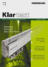
Zoom in to details of an imported DXF fi le Part program on the basis of the imported DXF fi le
– General New Features<br />
A number of new programming features<br />
support the machinist and open new<br />
possibilities.<br />
Contour pockets: Subcontours can have<br />
different depths (upgrade function)<br />
The powerful contour pocket function is<br />
available for machining complex contours.<br />
In smarT.NC you can defi ne up to 9 subcontours<br />
(pockets or islands), and in<br />
conversational programming up to 12 subcontours,<br />
for machining a contour pocket.<br />
These subcontours can contain up to 8192<br />
contour elements. Until now the depth of a<br />
pocket was globally specifi ed. Now you<br />
can assign a separate depth to each<br />
subcontour. If the subcontour is an island,<br />
the iTNC interprets the “depth” entered as<br />
the height of the island.<br />
Separate machining units are now<br />
available in smarT.NC for fi ne roughing,<br />
side fi nishing and fl oor fi nishing, thereby<br />
complementing the machining of a<br />
contour pocket.<br />
Cutting speed vc as alternate entry to<br />
the spindle shaft speed S<br />
When selecting a tool, you can now enter<br />
a cutting speed vc in m/min instead of the<br />
spindle speed S in rpm.<br />
Freely defi nable tables in form view<br />
The iTNC can now show all freely defi nable<br />
tables, meaning all tables of fi le type .TAB,<br />
in a form view. This view is especially<br />
useful for large amounts of data.<br />
Expanded look-ahead<br />
In order to machine contours rapidly, the<br />
control calculates the geometry ahead of<br />
time—previously up to 256 blocks. Usually<br />
this suffi ces completely. Today’s computing<br />
power, however, makes it possible to<br />
calculate further in advance. The machine<br />
manufacturer can now parameterize the<br />
look-ahead function through a machine<br />
parameter. The maximum value is 1<strong>02</strong>4<br />
blocks—for a look-ahead capability<br />
covering four times as many blocks as<br />
before. This will only have an effect in NC<br />
programs with extremely short positioning<br />
blocks.<br />
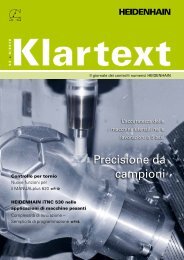
Separate depths are defi nable for subcontours<br />
Tables in form view are freely defi nable<br />
5
New Programming Functions<br />
– smarT.NC<br />
Mid-program startup with graphic<br />
support (upgrade function)<br />
The pattern generator in smarT.NC is a<br />
powerful feature for defi ning machining<br />
positions fl exibly and with graphic support.<br />
The positions are saved blockwise in point<br />
tables for convenient reuse at other<br />
locations for other operations. Now the reentry<br />
into a machining program has been<br />
adapted to this fl exible function: smarT.NC<br />
detects your entry into a unit in which<br />
machining positions are defi ned, and<br />
symbolically displays the positions in a<br />
preview window. You can now select via<br />
soft key at which position you would like to<br />
begin machining. smarT.NC then automatically<br />
inserts the appropriate tool and<br />
traverses to the selected position—of<br />
course only after your approval.<br />
CUT/COPY/PASTE of one or more units<br />
Using the key combinations you are<br />
familiar with from Windows, you can copy<br />
an entire unit or insert it at any other<br />
location in the program. Naturally, the<br />
SELECT BLOCK function you know from<br />
conversational programming is also<br />
available for the copying and pasting of<br />
multiple units.<br />
Feed rate also possible as FZ/FU/FMAX<br />
When specifying the feed rate, you can<br />
also enter a revolution feed rate in mm/rev<br />
or a cutting feed rate mm/tooth instead of<br />
in mm/min.<br />
6<br />
smarT.NC: mid-program startup
Tooltips displayed when using the<br />
mouse<br />
If you hold the mouse over an entry fi eld or<br />
selection box for more than one second,<br />
the iTNC displays a tooltip. Tooltips contain<br />
information or important notes about the<br />
respective function.<br />
Tool data editable during tool selection<br />
In the pop-up window for tool selection<br />
you can now also change the tool data<br />
shown there. The TNC automatically saves<br />
these changes in the tool table TOOL.T.<br />
Axis keys now position the cursor in<br />
forms as well<br />
Up to now, experienced conversational<br />
dialog programmers have been wanting to<br />
use the orange axis keys in smarT.NC for<br />
contour programming. Now they can. The<br />
orange I key (incremental/absolute<br />
switchover) and P key (polar/rectangular<br />
switchover) can now also be used.<br />
Automatic entry of workpiece blank<br />
into contour program<br />
When you create a new contour program,<br />
smarT.NC automatically takes the workpiece<br />
blank defi ned in the unit program.<br />
This transfer can be updated by soft key at<br />
any time.<br />
Incremental entry of machining<br />
positions<br />
When defi ning the positions directly in the<br />
form for each machining unit, the positions<br />
can now also be entered incrementally.<br />
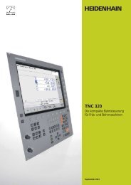
smarT.NC: Tooltips when using the mouse<br />
smarT.NC: Editing the tool data during tool selection<br />
7
New Programming Functions<br />
– Conversational Programming<br />
Point fi lter for smoothing NC programs<br />
created offl ine<br />
With this TNC function you can make<br />
contours smoother that were created on<br />
external programming systems. The fi lter<br />
function creates a copy of the original<br />
program, and then adds any points<br />
required by the parameters that you set.<br />
This smoothes the contour to allow the<br />
program to run more quickly and with<br />
less jerk.<br />
Conversational: new 3-D line graphics with powerful zoom<br />
function<br />
3-D line graphics, for 3-D display of tool<br />
center-point path (upgrade function)<br />
The new line graphics display the programmed<br />
contour in three dimensions.<br />
With the powerful zoom function you<br />
can also see the details. You should<br />
especially use the 3-D line graphics to<br />
inspect programs created offl ine for irregularities<br />
before machining, in order to avoid<br />
undesirable traces of the machining<br />
process on the workpiece. In order to<br />
fi nd the error location quickly, the currently<br />
active block of the 3-D line graphics<br />
appears highlighted in the left window.<br />
In addition, the respective programmed<br />
end points can be displayed to show any<br />
concentrations of points.<br />
8<br />
Manual traverse in the active tool-axis<br />
system (upgrade function)<br />
Use this function in the Manual and<br />
Electronic Handwheel operating modes,<br />
as well as during a program interruption in<br />
the Program Run, Full Sequence operating<br />
mode to move the tool with the external<br />
direction keys or the handwheel in the<br />
direction in which the tool axis is currently<br />
pointed. This function is especially useful<br />
in fi ve-axis programs if you need to retract<br />
the tool and do not have detailed information<br />
about the tool-axis direction.<br />
Conversational: simple editing of a preset table<br />
More Convenient Preset Table<br />
Now, you access a preset table directly<br />
with the PRESET TABLE soft key in the<br />
Manual operating mode. There are also<br />
new possibilities for saving values in the<br />
preset table:<br />
Use the actual position of the tool or dial<br />
gauge as the new preset<br />
Assign any value to the actual position of<br />
the tool or dial gauge<br />
Incrementally shift a preset already<br />
saved in the table<br />
Directly enter the new preset without<br />
calculation of the kinematics
– Programming Station<br />
Since the beginning of this year, the iTNC<br />
programming station has been shipped with<br />
a new keyboard. The new keyboard has a<br />
much leaner housing and includes the new<br />
smarT.NC keys. The following improvements<br />
are available in the programming station<br />
version 340494-<strong>02</strong>.<br />
•<br />
•<br />
•<br />
All software options and FCL<br />
functions fully enabled<br />
One special benefi t: the complete array<br />
of soft ware options and FCL functions<br />
available for the control are fully enabled<br />
here. This enables users of the licensed<br />
or free demo versions (down load at<br />
www.heidenhain.de/service) to amply<br />
test all functions and then decide<br />
whether an upgrade on the machine is<br />
worthwhile.<br />
Virtual keyboard<br />
Especially the users of the demo version<br />
of the programming station can get an<br />
even better idea of how easy it is to<br />
operate the TNC using the keyboard.<br />
Use the iTNC control panel to open a<br />
virtual TNC keyboard on the screen,<br />
providing the control‘s most important<br />
dialog initiation keys. You will need a<br />
screen resolution of at least 1280x1<strong>02</strong>4<br />
to be able to see the control screen and<br />
the virtual key board at the same time.<br />
PLC basic program optionally<br />
installable<br />
When installing the programming station<br />
software, you can now also install the<br />
PLC basic program. This lets you<br />
perform a “dry run” in the Program Run<br />
modes with the programs created on the<br />
programming station, and the position<br />
display runs as well.<br />
9
Overview<br />
– New Functions with the NC Software <strong>34049x</strong>-<strong>02</strong>:<br />
Mode of operation<br />
10<br />
Standard<br />
FCL <strong>02</strong><br />
Option<br />
Function<br />
General information DCM: Dynamic Collision Monitoring (only with MC 422B)<br />
USB support for peripheral memory devices (memory sticks, hard disks, CD-ROMs)<br />
DHCP (Domain host control protocol) and DNS (domain name server) possible for network settings<br />
• Freely defi nable tables visible also in form view<br />
• All soft keys revised<br />
Slovenian language<br />
• Czech user interface now with native characters<br />
• Confi gurable update procedure for future software updates (e.g. automatic update over<br />
USB storage devices)<br />
• Additional HR 420 functions:<br />
Selection of the active override possible on the HR 420<br />
Freely defi nable soft-key menu for machine functions<br />
• Smaller pop-up window when HR 420 is active, to improve legibility of axis positions on screen<br />
• Look-ahead can be confi gured via machine parameters<br />
• Calculation of dynamic load for tilting axes<br />
• Inclined tool machining with noncontrolled axes<br />
smarT.NC Direct loading of contours from DXF fi les and saving as smarT.NC contouring programs<br />
Cycles for coordinate transformation introduced<br />
PLANE function introduced<br />
Contour pocket: Separate depth can be assigned for each subcontour<br />
Mid-program startup with graphic support<br />
• Cutting speed as alternate entry to the spindle shaft speed<br />
• Feed rate can also be entered as Fz (feed per tooth) or Fu (feed per revolution)<br />
• Tool data can be edited in a pop-up window during tool selection<br />
• Axis keys now also position the cursor in the forms. The I key (incremental/absolute switchover)<br />
and P key (polar/rectangular switchover) now also function for contour programming.<br />
• CUT/COPY/PASTE of one or more units<br />
• Automatic entry of workpiece blank into contour program<br />
• Incremental entry of machining positions in forms for machining units<br />
• Tooltips displayed when using the mouse<br />
• Navigation through the forms using the axis keys
Mode of operation<br />
Conversational<br />
programming<br />
Standard<br />
FCL <strong>02</strong><br />
Option<br />
Function<br />
Reading of contours from DXF fi les and saving them as conversational programs<br />
Cycle for global setting of touch-probe parameters<br />
Point fi lter for smoothing NC programs created offl ine<br />
3-D line graphics for verifi cation of programs created offl ine<br />
Manual traverse in the active tool-axis system<br />
• Cutting speed as alternate entry to the spindle shaft speed<br />
• Simplifi cation when working with the preset table, incremental correction of preset values possible,<br />
correction of the active preset possible<br />
• Contour pockets can now contain signifi cantly more contour elements<br />
• Consideration of an active basic rotation in manual probe cycles<br />
• Measuring log for probing cycles can now also be displayed on the screen during program<br />
interruption<br />
• FK transformation selectable as structured plain-language or linearized plain-language<br />
ISO • PLANE function also in possible in ISO<br />
Programming<br />
Station<br />
• Virtual keyboard display in new version of the programming station<br />
• PLC program provided for optional installation (can be used to move axes)<br />
• Access to the PLC with the keyword “PLC”<br />
• All options and FCL functions are fully enabled<br />
11
Overview<br />
– All Options in the NC Software <strong>34049x</strong>-<strong>02</strong><br />
Option<br />
number<br />
12<br />
Option Id. Nr. Comment<br />
0 Additional axis 354 540-01 Additional control loops 1 to 8<br />
1 353 904-01<br />
2 353 905-01<br />
3 367 867-01<br />
4 367 868-01<br />
5 370 291-01<br />
6 370 292-01<br />
7 370 293-01<br />
8 Software option 1<br />
(for MC 420)<br />
9 Software option 2<br />
(for MC 420)<br />
367 591-01 Machining with a rotary table<br />
Programming of cylindrical contours as if in two axes<br />
Linear feed rate<br />
Coordinate transformation<br />
Tilting the working plane, PLANE function<br />
Interpolation<br />
Circular In 3 axes with tilted working plane<br />
367 590-01 3-D machining<br />
Motion control with minimum jerk<br />
3-D tool compensation through surface normal vectors<br />
Using the the electronic handwheel to move the swivel head with during<br />
program run<br />
Position of the tool tip remains unchanged thanks to Tool Center Point<br />
Management (TCPM)<br />
Keeping the tool normal to the contour<br />
Tool radius compensation normal to the direction of the tool<br />
Interpolation<br />
Linear in 5 axes (export permit required)<br />
Spline: execution of splines (3rd degree polynomial)<br />
Block processing time 0.5 ms<br />
18 <strong>HEIDENHAIN</strong> DNC 526 451-01 Communication with external PC applications over COM components<br />
40 DCM collision 526 452-01 Dynamic Collision Monitoring (only with MC 422B)<br />
41 Additional language 530 184-01 User interface in Slovenian<br />
42 DXF converter 526 450-01 Load and convert DXF contours<br />
53 FCL 529 969-01 Feature Content Level<br />
<strong>DR</strong>. <strong>JOHANNES</strong> <strong>HEIDENHAIN</strong> <strong>GmbH</strong><br />
Dr.-Johannes-Heidenhain-Straße 5<br />
83301 Traunreut, Germany<br />
{ +49 (8669) 31-0<br />
| +49 (8669) 5061<br />
E-Mail: info@heidenhain.de<br />
www.heidenhain.de<br />
571 500-21 · 5 · 6/2006 · H · Printed in Germany · Subject to change without notice<br />
For more information<br />
Brochure: iTNC 530