FCF Installation / Operation Manual - Techwebasto.com
FCF Installation / Operation Manual - Techwebasto.com
FCF Installation / Operation Manual - Techwebasto.com

Create successful ePaper yourself
Turn your PDF publications into a flip-book with our unique Google optimized e-Paper software.
6/2012<br />
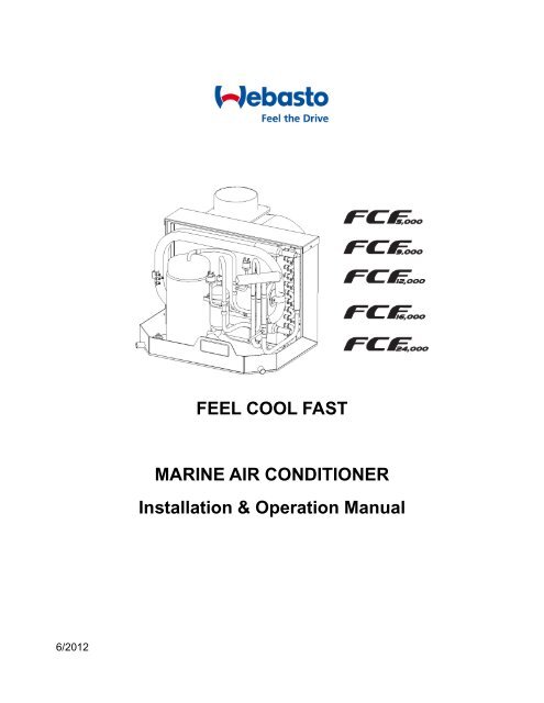
FEEL COOL FAST<br />
MARINE AIR CONDITIONER<br />
<strong>Installation</strong> & <strong>Operation</strong> <strong>Manual</strong>
Table of Contents<br />
INTRODUCTION ................................................................................................................................................. 4<br />
PACKAGED COMPONENTS .............................................................................................................................. 5<br />
OVERVIEW ......................................................................................................................................................... 5<br />
INSTALLATION ................................................................................................................................................... 6<br />
Unpacking and Inspection ....................................................................................................................................... 6<br />
Safety Considerations ............................................................................................................................................. 6<br />
Placement of System ............................................................................................................................................... 7<br />
Blower Assembly ..................................................................................................................................................... 9<br />
Mounting Brackets ................................................................................................................................................... 9<br />
Supply & Return Air Grilles and Transition Boxes.................................................................................................... 9<br />
Ducting .................................................................................................................................................................. 10<br />
Seawater Pump and Plumbing .............................................................................................................................. 10<br />
Electrical Connections, Grounding and Bonding ................................................................................................... 12<br />
Digital Display <strong>Installation</strong> ...................................................................................................................................... 13<br />
Electric Box <strong>Installation</strong>.......................................................................................................................................... 13<br />
<strong>Installation</strong> Checklist (Review Prior To <strong>Installation</strong>) ............................................................................................... 14<br />
Wiring Diagrams .................................................................................................................................................... 15<br />
OPERATION ...................................................................................................................................................... 18<br />
Digital Display <strong>Operation</strong> ....................................................................................................................................... 18<br />
Power ON/OFF.......................................................................................................................................................... 19<br />
Sleep Mode of the digital display ............................................................................................................................... 19<br />
FAN Control ............................................................................................................................................................... 19<br />
Temperature Setting ................................................................................................................................................... 19<br />
Mode Setting .............................................................................................................................................................. 19<br />
Button / Function and Description (Cover Closed) ................................................................................................... 21<br />
Button / Function and Description (Cover Open) ...................................................................................................... 22<br />
ERROR CODES ................................................................................................................................................ 24<br />
TROUBLESHOOTING ...................................................................................................................................... 25<br />
MAINTENANCE ................................................................................................................................................ 27<br />
Reversing Valves ................................................................................................................................................... 27<br />
Seawater Strainer .................................................................................................................................................. 27<br />
Condenser Coil Cleaning (Seawater Acid Flush) .................................................................................................. 27<br />
Return Air Filters .................................................................................................................................................... 27<br />
Winterization .......................................................................................................................................................... 28<br />
UNIT DIMENSIONS & TECHNICAL SPECIFICATIONS ................................................................................... 29<br />
LIMITED WARRANTY ....................................................................................................................................... 30<br />
TECHNICAL ASSISTANCE ............................................................................................................................... 30
Introduction<br />
<strong>Operation</strong> / <strong>Installation</strong> <strong>Manual</strong> – <strong>FCF</strong> 5000, 9000, 12000, 16000, 24000<br />
Thank you for your purchase. No matter which of the following features was the reason for your purchase, we are sure it<br />
will meet your needs and give many years of efficient and trouble free use. These air conditioners are designed for<br />
marine applications incorporating the following features:<br />
• Compact design<br />
• High efficiency rotary <strong>com</strong>pressors (5-24K)<br />
• Cupronickel condenser coil<br />
• Raised lance fin designed evaporator coil<br />
• Polyester coated 2” (50mm) deep drain pan with four condensate drain locations<br />
• Anti-vibration base pan<br />
• Pre-charged and pre-wired systems for easy connections<br />
• 3-speed fan motor. This eliminates all harmonic sounds and rumbles.<br />
• Rotatable blower assembly<br />
The controller offers the most technologically advanced design specifically made for the unique requirements of marine<br />
air conditioning. The controller has been designed with the following "user friendly" features:<br />
• Non-volatile memory<br />
• Low voltage display panel<br />
• LED cabin temperature displayed in Fahrenheit or Celsius<br />
• Multiple fan speed selections<br />
• Compressor pressure fail safe protection<br />
• Dehumidification Mode for humidity control<br />
This manual is intended to provide the information necessary to ensure proper installation, operation, and maintenance<br />
of a <strong>FCF</strong> air conditioner. Improper installation can result in unsatisfactory performance and/or premature failure. Before<br />
proceeding, please read this manual in its entirety. In the interest of product improvement, specifications and design are<br />
subject to change without prior notice.<br />
Page 4
<strong>Operation</strong> / <strong>Installation</strong> <strong>Manual</strong> – <strong>FCF</strong> 5000, 9000, 12000, 16000, 24000<br />
Packaged Components<br />
ITEM QUANTITY<br />
Air Conditioning unit 1<br />
Mounting Bracket 4<br />
Fuses (3.15 AL 250V) 2<br />
Remote controller / Batteries 1<br />
Digital Display / Cable 1<br />
Duct Ring / Hardware 1<br />
Blower Insulation Foam 1<br />
<strong>Installation</strong> / <strong>Operation</strong> <strong>Manual</strong> 1<br />
Overview<br />
HOW IT WORKS<br />
All units are manufactured without service ports<br />
Your self-contained air conditioner consists of four main <strong>com</strong>ponents and a refrigerant gas circulating through the system.<br />
The BLOWER draws warm cabin air across the fins on the EVAPORATOR where the heat from the air is transferred to<br />
the refrigerant in the evaporator coil. As the refrigerant evaporates from a liquid into a gas, it absorbs the heat from the<br />
cabin air. The COMPRESSOR then <strong>com</strong>presses the refrigerant gas and pumps it through the outer tube in the<br />
CONDENSER COIL. The seawater pump circulates cool seawater through the inner tube in the condenser coil; this<br />
cools the refrigerant and condenses it into a liquid. The heat from the refrigerant is exchanged to the seawater and<br />
discharged overboard. The liquid refrigerant is then passed through the EVAPORATOR COIL and the cycle repeats;<br />
removing heat from the cabin air lowering its temperature. The cooled air is blown through the ducting and out the supply<br />
air grille(s). For reverse cycle heating, the refrigerant flows in the opposite direction through the reversing valve. Heat is<br />
transferred from the seawater in the condenser coil to the refrigerant and then to the air blowing through the evaporator<br />
into the cabin. Seawater temperature will directly affect the air conditioners efficiency. This air conditioner can effectively<br />
cool your boat in water temperatures up to 90°F and heat in water temperatures as low as 40°F.<br />
Page 5
<strong>Installation</strong><br />
Unpacking and Inspection<br />
<strong>Operation</strong> / <strong>Installation</strong> <strong>Manual</strong> – <strong>FCF</strong> 5000, 9000, 12000, 16000, 24000<br />
When the equipment is received, all items should be carefully checked according to the packaged <strong>com</strong>ponents list within<br />
this manual to ensure all <strong>com</strong>ponents have been received. Examine <strong>com</strong>ponents for shipping damage. If the unit is<br />
damaged, the carrier should make the proper notation on the delivery receipt acknowledging the damage.<br />
Safety Considerations<br />
VERY IMPORTANT: Never install your air conditioner in the bilge or engine room areas. Ensure that the selected location<br />
is sealed from direct access to bilge and/or engine room vapors. Do not terminate condensate drain line within 3’ (914mm)<br />
of any outlet of engine, generator exhaust system, <strong>com</strong>partment housing an engine or generator, or in a bilge, unless the<br />
drain is connected properly to a sealed condensate or shower sump pump. Seal all cabin penetrations around<br />
condensate hoses to eliminate harmful bilge fumes in the cabin living spaces.<br />
<strong>Installation</strong> and servicing of this system can be hazardous due to system pressure and electrical <strong>com</strong>ponents. When<br />
working on this equipment, always observe precautions described in the literature, tags and labels attached to the unit.<br />
Follow all safety precautions. Wear safety glasses and work gloves and place a fire extinguisher close to the work area.<br />
The following is a summary of the labels on the unit:<br />
Indicates an imminently hazardous situation which, if not avoided, will result in death or serious<br />
injury.<br />
Indicates a potentially hazardous situation which, if not avoided, could result in death or serious<br />
injury.<br />
Indicates a potentially hazardous situation which, if not avoided, may result in minor or moderate<br />
injury.<br />
Special note. Make sure to read before proceeding.<br />
Electrical shock hazard. Disconnect voltage at main panel or power source before opening<br />
any cover. Failure to <strong>com</strong>ply may result in injury or death.<br />
This <strong>com</strong>ponent does not meet federal requirements for ignition protection. Do not install in<br />
spaces containing gasoline engines, tanks, LPG/CPG cylinders, regulators, valves or fuel line<br />
fittings. Failure to <strong>com</strong>ply may result in injury or death.<br />
Notice the 115V series and the 230V series are charged with Hydro fluorocarbon (HFC) refrigerant<br />
R410A. Effective July 1, 1992, it shall be unlawful for any person to knowingly vent or otherwise<br />
knowingly release any class 1 (CFC) or class 2 (H CFC) substance as a refrigerant in a manner<br />
which permits such substance to enter the atmosphere per the clean air act of 1990. Public law<br />
101-549 title IV section 608-c. Failure to <strong>com</strong>ply may result in severe penalties, including fines and<br />
imprisonment.<br />
To minimize the hazard of electrical shock and personal injury, this <strong>com</strong>ponent must be<br />
effectively grounded. Refer to the installation guidelines for further information. Caution! High<br />
<strong>com</strong>pressor temperature is normal. Do not touch!<br />
Page 6
<strong>Operation</strong> / <strong>Installation</strong> <strong>Manual</strong> – <strong>FCF</strong> 5000, 9000, 12000, 16000, 24000<br />
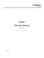
Placement of System<br />
Selecting a good location for your air conditioner is the most important part of your preparation. Be sure to consider the<br />
size of the area you are cooling, the air distribution needs, and the size of the unit you have chosen. Keeping in mind that<br />
cool air has a tendency to fall; it is highly re<strong>com</strong>mended that you locate the supply air grille as high as possible in the<br />
cabin. The ducting should be run as straight, smooth and taut as possible minimizing the number of 90 degree<br />
bends. See diagram below.<br />
Size of Sealed room<br />
Ensure the area which the air conditioner is located is not too small otherwise it will affect proper operation. See the<br />
diagram below.<br />
Page 7
The unit should be installed as low as possible, BUT NEVER IN THE BILGE<br />
OR ENGINE ROOM AREAS, ENSURE THAT THE SELECTED LOCATION<br />
IS SEALED FROM DIRECT ACCESS TO BILGE AND/OR ENGINE ROOM<br />
VAPORS. Installing the unit as low as possible (such as under a V-berth,<br />
dinette seat or bottom of a locker) and ducting the supply<br />
air as high as possible, creates an ideal airflow condition. This type of<br />
installation will prevent short or premature cycling.<br />
The unit should be positioned on a firm, level, horizontal surface and the<br />
condensate drain line should run downward from the unit to a suitable drain<br />
location. Plan all Connections, which must be made including ducting,<br />
condensate drain, and seawater in and out, electrical power connections,<br />
location of control, and seawater pump placement, to assure easy access for<br />
routing and servicing.<br />
<strong>Operation</strong> / <strong>Installation</strong> <strong>Manual</strong> – <strong>FCF</strong> 5000, 9000, 12000, 16000, 24000<br />
Page 8<br />
Tools required:<br />
• Screws drivers<br />
• Pliers<br />
• Pipe wrench<br />
• Wire cutters/crimpers<br />
• Drill & bit set<br />
• Jigsaw<br />
• Duct tape<br />
• Electrical tape<br />
• Thread sealer<br />
• Bedding <strong>com</strong>pound to seal thru<br />
hull fittings<br />
• Hardware to secure unit, pump,<br />
strainer, grilles & electrical box
<strong>Operation</strong> / <strong>Installation</strong> <strong>Manual</strong> – <strong>FCF</strong> 5000, 9000, 12000, 16000, 24000<br />
Condensate Drains<br />
The condensate drain pan is 2” (50mm) deep with four drain locations. During conditions of high humidity, condensate<br />
may be produced at a rate of approximately 1/2 gallon per hour (1.9 liters per hour). It is important to route condensate<br />
drains downward to a sump pump. It is not re<strong>com</strong>mended to route condensate drains to the bilge. After the condensate<br />
drain installation is <strong>com</strong>plete, test the installation by pouring water into the pan and checking for good flow.<br />
For installation of the condensate drain:<br />
● Attach a 5/8” I.D. reinforced hose to the hose barb and secure with stainless steel hose clamps.<br />
● Install the condensate drain hose downhill from the unit and aft to a sump.<br />
● Four drain fittings may be used and the hoses joined together with a tee fitting provided there is a minimum 2"<br />
drop from the bottom of the base pan to the tee connection.<br />
Blower Assembly<br />
Do not terminate condensate drain line within three 3’ (914mm) of any outlet of engine, generator exhaust<br />
systems, <strong>com</strong>partment housing an engine or generator, nor in a bilge, unless the drain is connected<br />
properly to a sealed condensate or shower sump pump. Seal all condensate hose penetrations.<br />
You can achieve multi-directional supply air discharge from a single unit by rotating the blower to the desired position in<br />
45° increments. It is ideal for tight installations as 360° of rotation is available with which to position the blower. Its<br />
advanced design allows the blower to be easily removed for rotating or servicing by removing 4 screws. Rotate the<br />
blower to allow the most direct flow of air to the supply air grille.<br />
After the blower has been properly positioned, make sure to install the supplied<br />
strip of insulation foam around the collar to prevent condensation build up.<br />
Mounting Brackets<br />
The air conditioning unit is supplied with a base pan that also serves as a<br />
condensate pan. Mounting clip brackets (4) are provided to secure the base pan to<br />
a flat, horizontal surface. Hardware for the mounting clips must be provided by the<br />
installer as needed.<br />
Supply & Return Air Grilles and Transition Boxes<br />
Install the supply air grille as high as possible in a location that will provide uniform air distribution throughout the cabin.<br />
Grille louvers should be directed properly for best air flow. The return air grille should be installed as low and close to the<br />
air conditioner as possible to insure direct uninterrupted airflow to the evaporator. The return air grille should have a<br />
minimum four inches (4') of clearance in front of it, free from any furniture or other obstructions. In no instance should a<br />
supply air discharge be directed towards a return air grille, as this will cause the system to short cycle. Allow for adequate<br />
clearance behind the supply air grille(s) for the transition box and ducting connection. See the Maintenance section of<br />
this manual for return air filter cleaning instructions.<br />
Page 9
Ducting<br />
<strong>Operation</strong> / <strong>Installation</strong> <strong>Manual</strong> – <strong>FCF</strong> 5000, 9000, 12000, 16000, 24000<br />
Good airflow is critical for the performance of the entire system. It is highly dependent on the quality of the ducting<br />
installation. The ducting should be run as straight, smooth and taut as possible minimizing the number of 90 degree<br />
bends (two tight 90° bends can reduce airflow by 25%). If a transition box is used, the total area of supply air ducts going<br />
out of the box should at least equal the area of the supply duct feeding the box. To calculate the square inch area of a<br />
round duct, multiply the radius by itself (r 2 ) and multiply that number by 3.1416(π). The following is a summary of proper<br />
ducting connections:<br />
1. Pull back the fiberglass insulation exposing the inner Mylar duct hose.<br />
2. Slide the Mylar duct hose around the mount ring until it bottoms out.<br />
3. Screw 3 or 4 stainless steel sheet metal screws through the duct hose into the transition ring. Make sure to<br />
catch the wire in the duct hose with the heads of the screws. Use finish washers with the screws if necessary.<br />
Do not use band clamps, as the hose will slide off.<br />
4. Wrap duct tape around the ducting and ring joint to prevent any air leaks.<br />
5. Pull the insulation back up over the Mylar to the ring and tape this joint.<br />
6. Remove excess ducting and use the same connection method at the supply air grille.<br />
All ducting should:<br />
● Be insulated and appropriately sized for each application.<br />
● Run as smoothly and taut as possible.<br />
● Have as few bends or loops as possible.<br />
● Be securely fastened to prevent sagging or chafing during vessel operation.<br />
● Have all excess ducting lengths trimmed off.<br />
● Not be flattened or kinked.<br />
● Be properly protected against potential damage when routed through open areas or bulkheads.<br />
Seawater Pump and Plumbing<br />
Several guidelines should be followed during the installation of the seawater system. If the circulation pump is centrifugal<br />
and not self-priming, it must be mounted so that it is always at least 1’ (305mm) below the water line regardless of which<br />
tack the vessel is on. Pump may be mounted horizontally or vertically, however, the discharge must always be above the<br />
inlet. Pump head should be rotated toward the direction of water flow. Install the seawater speed scoop intake as far<br />
below the water line and as close to the keel as possible in any application, but especially on a sailboat, to keep<br />
the intake in the water when the boat heels over so that air does not get into the system. The speed scoop intake<br />
must face forward and not be shared with any other pump. A seawater strainer is mandatory between the shut off valve<br />
(seacock) and the pump to protect the pump from any foreign matter. Failure to install a seawater strainer will void the<br />
pump warranty. The seawater system should be installed with an upward incline from the speed scoop & seacock,<br />
through the strainer, to the inlet of the pump, next to the inlet of the air conditioning unit's condenser coil. The discharge<br />
from the air conditioning unit should run to the seawater outlet thru-hull fitting that should be located where it can be<br />
visually inspected for water flow as close to the waterline to reduce noise. All hose connections should be secured using<br />
double/reversed stainless steel hose clamps. Use thread sealer on all threaded connections.<br />
Page 10
<strong>Operation</strong> / <strong>Installation</strong> <strong>Manual</strong> – <strong>FCF</strong> 5000, 9000, 12000, 16000, 24000<br />
Summary of the seawater system installation:<br />
1. Install the speed scoop thru-hull inlet as close to the keel and as far below the water line as possible, facing<br />
forward. Bed the scoop with a marine sealant designed for underwater use.<br />
2. Install a bronze, full flow seacock on the speed scoop thru-hull inlet.<br />
3. Install a seawater strainer below the level of the pump with access to filter.<br />
4. Mount the pump above the strainer and at least 1’ (305mm) below the waterline.<br />
5. Connect the seacock and strainer with an uphill run of 5/8" reinforced marine grade hose.<br />
6. Connect the discharge from the pump uphill to the bottom inlet of the air conditioning unit's condenser coil with<br />
5/8" hose. Connect the discharge from the condenser coil to the overboard discharge thru-hull fitting with 5/8"<br />
hose.<br />
7. Avoid loops, high spots or the use of 90° elbows with seawater hose (each 90° elbow is equivalent to 2.5'<br />
(762mm) of hose and a 90° elbow on the pump outlet is equivalent to 20' (6.1m) of hose).<br />
8. Double clamp all hose connections with stainless steel clamps, reversing the clamps.<br />
9. Use thread sealer on all threaded connections.<br />
10. Connect all metallic parts in contact with seawater to the vessel's bonding system including the speed<br />
scoop inlet, strainer, pump and the air conditioner. Failure to do so will void warranty.<br />
Page 11
Electrical Connections, Grounding and Bonding<br />
<strong>Operation</strong> / <strong>Installation</strong> <strong>Manual</strong> – <strong>FCF</strong> 5000, 9000, 12000, 16000, 24000<br />
Turn off air conditioner power supply circuit breaker before opening electric box.<br />
All air conditioner units have a terminal strip mounted inside the electric box. The terminal strip is labeled for proper<br />
connections of the electrical supply, ground wires and pump circuits. A wiring diagram is provided in the electrical box<br />
and later in this manual. The wiring diagram in the electrical box supersedes any found in this manual and ABYC<br />
standards. The correct size circuit breaker should be used to protect the system as specified within the technical<br />
specifications section. A minimum of 12 AWG boat cable should be used to supply power to the air conditioning unit and<br />
the seawater pump. All connections should be made with ring or captive fork terminals.<br />
Each air conditioner installed requires its own dedicated circuit breaker. If there is only one air conditioner installed, the<br />
seawater pump does not require a circuit breaker; the wiring from the seawater pump is connected to the terminal strip in<br />
the electric box. If two or more air conditioners use the same seawater pump, the pump wires will be connected to a<br />
pump relay, Please refer to the wiring diagram. Electrical connections in the bilge and/or below the waterline should use<br />
heat shrink type butt splices. Field wiring must <strong>com</strong>ply with ABYC electrical codes. Power to the unit must be within the<br />
operating voltage range indicated on the data plate. Properly sized marine grade circuit breakers must be installed for<br />
circuit protection. All units must be effectively grounded to minimize the hazard of electrical shock and personal injury.<br />
Make sure to connect the green grounding wire to the GRND stud within the electrical box per ABYC standard E-8, or<br />
equivalent.<br />
1. Connections between the vessel's AC system grounding conductor (green wire) and the vessel’s DC (Direct<br />
Current) negative or bonding system should be made as part of the vessel's wiring, per ABYC standard E-9, or<br />
equivalent.<br />
• When servicing or replacing existing equipment that contains a chassis-mounted ground stud, the<br />
installer must check the vessel's wiring for the existence of the connection required in item 1 above.<br />
The air conditioner unit must be connected to the ship's bonding system to prevent corrosion<br />
due to stray electrical current or voltage. All pumps, metallic valves and fittings in the seawater<br />
circuit that are isolated from the air conditioning unit by PVC or rubber hoses must be<br />
individually bonded to the vessels bonding system. This will help eliminate any possibility of<br />
corrosion due to stray current or voltage.<br />
Page 12
<strong>Operation</strong> / <strong>Installation</strong> <strong>Manual</strong> – <strong>FCF</strong> 5000, 9000, 12000, 16000, 24000<br />
Digital Display <strong>Installation</strong><br />
DO NOT turn the unit off and immediately turn it back on. Wait at least 30 seconds for refrigerant<br />
pressures to stabilize.<br />
Before mounting the digital display, consider the location. The digital display<br />
should never be mounted in direct sunlight or exposed to excessive<br />
moisture.<br />
NOTE: The display cable must be grounded at the electrical box.<br />
Electric Box <strong>Installation</strong><br />
Mount the electric box using four M5 screws.<br />
Mount the electric box in a cool dry location leaving plenty of room for access.<br />
Page 13
<strong>Installation</strong> Checklist (Review Prior To <strong>Installation</strong>)<br />
Seawater cooling system:<br />
Mounting<br />
Electrical<br />
<strong>Operation</strong> / <strong>Installation</strong> <strong>Manual</strong> – <strong>FCF</strong> 5000, 9000, 12000, 16000, 24000<br />
Speed scoop located as far below the water line and as close to the keel as possible<br />
Shut off valve (sea cock) and speed scoop properly sealed and tightened<br />
Seawater pump is at least 1’ (305mm) below water line and securely mounted<br />
Strainer mounted below pump with access to filter<br />
Double/reversed stainless steel hose clamps on all hose connections<br />
Thread sealer on all threaded connections<br />
Hose runs uphill from speed scoop and sea cock to strainer, pump and air conditioning unit, then downhill (if<br />
possible) from air conditioner unit to overboard discharge<br />
Water flowing freely from overboard discharge while pump is running<br />
Pump relay panel, if used, must have its own circuit breaker sized for the pump (20 amp max)<br />
All metal fittings should be bonded<br />
Not in engine room or bilge area, must be sealed away from exhaust or fumes<br />
Proper spacing allowed around unit<br />
Attached to solid level platform with hold down brackets provided<br />
Condensate drain routed aft and down hill to a sealed sump (not bilge)<br />
All penetrations to bilge area sealed<br />
Blower rotated toward supply air grille<br />
All butt connections on pumps are tightly crimped and covered with heat shrink<br />
AC power source installed and grounded/bonded in accordance with ABYC standards<br />
Control wires connected to terminal strip with captive fork or ring terminals<br />
Circuit breakers sized according to technical specifications section.<br />
Pump Relay Panel (if used) has a dedicated circuit breaker sized for the pump but not to exceed 20 amps<br />
maximum.<br />
Grilles and Ducting<br />
Supply air grille mounted as high as possible<br />
Return air grille mounted as low and as close to the air conditioner as possible<br />
Return air grille mounted away from bilge vapors or exhaust fumes<br />
Ducting is pulled taut, straight, smooth and properly connected with no excess<br />
Quick Start <strong>Operation</strong>s Checklist<br />
Ensure seawater intake ball valve (sea cock) is open.<br />
Turn on the air conditioners circuit breaker. If the seawater pump has its own circuit breaker, make sure to turn it<br />
on.<br />
Turn the system on. Set the desired cabin temperature (set point).<br />
Check for a steady solid stream of water from the overboard discharge.<br />
Verify that there is steady airflow out of the supply air grille<br />
If the unit does not appear to be operating properly, refer to troubleshooting guidelines. Note: Do not turn the<br />
unit off and immediately back on. Allow at least 30 seconds for refrigerant pressure equalization.<br />
Page 14
<strong>Operation</strong> / <strong>Installation</strong> <strong>Manual</strong> – <strong>FCF</strong> 5000, 9000, 12000, 16000, 24000<br />
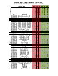
Wiring Diagrams<br />
Power 115V ~ 60Hz<br />
115V ~ 60Hz Line In L<br />
115V ~ 60Hz Neutral N<br />
Cooling Pump Line In 1<br />
Cooling Pump Neutral 2<br />
Power 208V / 230V ~ 60Hz<br />
208V / 230V ~ 60Hz Line In L<br />
208V / 230V ~ 60Hz Neutral N<br />
Cooling Pump Line In 1<br />
Cooling Pump Neutral 2<br />
Fuse = 3.15 AL 250V<br />
Page 15
Fuse = 3.15 AL 250V<br />
Fuse = 3.15 AL 250V<br />
<strong>Operation</strong> / <strong>Installation</strong> <strong>Manual</strong> – <strong>FCF</strong> 5000, 9000, 12000, 16000, 24000<br />
Page 16
<strong>Operation</strong> / <strong>Installation</strong> <strong>Manual</strong> – <strong>FCF</strong> 5000, 9000, 12000, 16000, 24000<br />
Fuse = 3.15 AL 250V<br />
Page 17
<strong>Operation</strong><br />
Digital Display <strong>Operation</strong><br />
<strong>Operation</strong> / <strong>Installation</strong> <strong>Manual</strong> – <strong>FCF</strong> 5000, 9000, 12000, 16000, 24000<br />
• Don't install the digital display in a location where it can get wet.<br />
• Don’t knock, throw or open the digital display.<br />
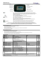
1. Remote receiver 6. Fan control button<br />
2. Display 7. Temp. Setting button (Increasing)<br />
3. Fan speed display (HIGH-MID-LOW and AUTO speed) 8. Temp. Setting button (Decreasing)<br />
4. Display of mode operation (COOL-DEHUMIDIFY-HEAT and AUTO) 9. ON/OFF button<br />
5. Mode button<br />
The digital display has a built in memory function that’s will retain the last modes settings. Settings include operation<br />
mode, set temperature, operation fan speed, and the temperature display format.<br />
In cooling / heating / dehumidify mode, the pump starts before the <strong>com</strong>pressor starts, stops after a<br />
5 second delay of the <strong>com</strong>pressor.<br />
Page 18
<strong>Operation</strong> / <strong>Installation</strong> <strong>Manual</strong> – <strong>FCF</strong> 5000, 9000, 12000, 16000, 24000<br />
Power ON/OFF<br />
• Press ON/OFF button to turn the unit display on. Press the ON/OFF button a second time to select mode<br />
and start operation.<br />
• While the display is active press the ON/OFF button once to turn the unit OFF. Press the ON/OFF button a<br />
second time if the display has already entered sleep mode to turn the unit OFF.<br />
Sleep Mode of the digital display<br />
The ambient temperature display will automatically enter a sleep status within 5 minutes of inactivity. Press any<br />
button on the display or the remote controller to wake the display.<br />
Note: Normal unit operation will continue while in sleep mode, it’s only the digital display that turns off.<br />
FAN Control<br />
• Press the FAN button, the fan speed will change in the following order:<br />
→ HIGH →MID → LOW → AUTO →<br />
• In “DEHUMIDIFY” mode, the fan will work at low speed automatically<br />
Temperature Setting<br />
• Press temperature setting key<br />
▲To increase in 1 o increments<br />
▼ To decrease in 1 o increments<br />
• The setting range of temperature in each mode:<br />
COOL 61°F 86°F or 16°C 30°C<br />
DEHUMIDIFY 61°F 86°F or 16°C 30°C<br />
HEAT 61°F 86°F or 16°C 30°C<br />
FAN In this mode, temperature cannot be changed.<br />
AUTO In this mode, temperature cannot be changed.<br />
Mode Setting<br />
• Press this key to change the operation mode in order of<br />
COOL Mode <strong>Operation</strong><br />
→ COOL → DEHUMIDIFY → FAN → HEAT → AUTO →<br />
• In “COOL” mode, the LED next to the icon will illuminate when mode is selected on the digital display.<br />
● If room temperature is higher than set temperature, the unit runs in COOL mode.<br />
● If set temperature is higher than room temperature then only the fan will run.<br />
DEHUMIDIFY Mode <strong>Operation</strong><br />
Page 19
<strong>Operation</strong> / <strong>Installation</strong> <strong>Manual</strong> – <strong>FCF</strong> 5000, 9000, 12000, 16000, 24000<br />
• In “DEHUMIDIFY” mode, the LED next to the icon will illuminate when mode is selected on the digital<br />
display.<br />
• In DEHUMIDIFY mode, if the indoor temperature is higher than temperature setting, the unit will run in cooling<br />
mode and the fan will run on low speed.<br />
FAN Mode <strong>Operation</strong> Procedure<br />
• In “FAN” mode, the room temperature will be displayed and the temperature cannot be set.<br />
• Temperature cannot be set in this operation mode.<br />
HEAT Mode <strong>Operation</strong><br />
• In “HEAT” mode, the LED next to the icon will illuminate when mode is selected on the digital display.<br />
• If room temperature is lower than set temperature, the unit runs in HEAT mode<br />
• If set temperature is lower than room temperature, then only the fan will run<br />
AUTO Mode <strong>Operation</strong><br />
• In “AUTO” mode, the LED marked AUTO will appear on the digital display. The temperature cannot be set; the<br />
system will run automatically in the appropriate mode according to the difference between room temperature<br />
and set temperature.<br />
Display Fahrenheit or Centigrade<br />
• Pressing the ▲ and ▼ key simultaneously, will switch between Fahrenheit and Centigrade modes.<br />
Key Lock<br />
• Press ▼and FAN key simultaneously, all keys are locked. Press ▼and FAN key simultaneously again, to unlock<br />
the keys.<br />
• When keys are locked, the controller is locked out of system operation. “EE” will be displayed.<br />
Page 20
<strong>Operation</strong> / <strong>Installation</strong> <strong>Manual</strong> – <strong>FCF</strong> 5000, 9000, 12000, 16000, 24000<br />
Button / Function and Description (Cover Closed)<br />
Wakes up Digital Display<br />
Page 21
Button / Function and Description (Cover Open)<br />
<strong>Operation</strong> / <strong>Installation</strong> <strong>Manual</strong> – <strong>FCF</strong> 5000, 9000, 12000, 16000, 24000<br />
Page 22<br />
Liquid Crystal Display. Opening<br />
cover while unit is on will not<br />
affect unit operation.<br />
NOTE: This is a universal<br />
remote; the sleep and timer<br />
ON/OFF buttons are not used<br />
with this application.
<strong>Operation</strong> / <strong>Installation</strong> <strong>Manual</strong> – <strong>FCF</strong> 5000, 9000, 12000, 16000, 24000<br />
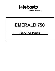
Battery Replacement in Remote Controller<br />
Remote controller battery requirements: Two AAA alkaline cells.<br />
Page 23<br />
1. Slide the cell cover downward to take out the worn<br />
cells. Replace the worn cells. (Note to the correct<br />
polarity).<br />
2. Close the cell cover.<br />
3. The LCD will show all the functional figures and letter<br />
codes after the batteries are installed. Wait<br />
approximately 10 seconds for normal use.<br />
4. The life span of batteries is approximately 1 year.<br />
(Depending on usage)<br />
5. If the remote controller doesn’t work after the batteries<br />
have been replaced, remove the back cover and press<br />
the “ACL” button to reset the controller.
Error Codes<br />
<strong>Operation</strong> / <strong>Installation</strong> <strong>Manual</strong> – <strong>FCF</strong> 5000, 9000, 12000, 16000, 24000<br />
When there are faults within the system, an error code will be displayed on the display controller: Power off the unit and<br />
contact professional service.<br />
Error code Description<br />
E1 Compressor high pressure protection<br />
E2 Evaporator freezing protection<br />
E3 Compressor low pressure protection<br />
E6 Communication error<br />
F0 Ambient temperature sensor error<br />
F1 Evaporator temperature sensor error<br />
Page 24
<strong>Operation</strong> / <strong>Installation</strong> <strong>Manual</strong> – <strong>FCF</strong> 5000, 9000, 12000, 16000, 24000<br />
Troubleshooting<br />
FAULT POSSIBLE REASON CORRECTION<br />
Will not start Air conditioning circuit breaker is off Turn circuit breaker on at ship's panel,<br />
Fan not<br />
running.<br />
No cooling or<br />
heating<br />
Page 25<br />
See control operation section in this manual.<br />
Display control is not turned on. Check wiring Diagram and correct if necessary.<br />
Fuse is broken Replaced with a new fuse. (3.15 AL 250V)<br />
Incorrect wiring at terminal strip. Disconnect power supply and open electric box, check<br />
wiring diagram, correct if necessary,<br />
Push-on butt connectors pulled apart during<br />
installation.<br />
Check power source (shore/generator) for proper voltage.<br />
Input line voltage is insufficient, Check wiring and terminals for proper sizes and<br />
connections.<br />
Check your specific control Troubleshooting section<br />
Temperature set point is above (in cooling) or below<br />
(in heating) ambient temperature<br />
Lower or raise set point.<br />
Obstructed seawater flow. Clean seawater strainer. Check for obstructions at speed<br />
scoop thru-hull inlet. Check for a good steady flow from the<br />
overboard discharge.<br />
Seawater pump maybe air-locked, Remove hose from pump discharge to purge air from line<br />
Refrigerant gas leaked. Check air conditioning unit for refrigerant oil leakage, call<br />
service technician.<br />
Seawater temperature too high for cooling or too low<br />
for heating.<br />
Coil is iced (in cooling) See below<br />
Fan is not running. See below<br />
Seawater temperature will directly affect the air conditioning<br />
unit’s efficiency. This air conditioning unit can effectively cool<br />
your boat in water temperature up to 90 0 F and heat (if<br />
reverse cycle option is installed) in water as low as 40 o F.<br />
Pressure switch or thermal overload opened. Check your specific control troubleshooting section.<br />
No Heating Reversing valve may be stuck. Tap reversing valve lightly with rubber mallet while unit is in<br />
heat mode, call for service if the problem cannot be solved.
Continued:<br />
FAULT POSSIBLE REASON CORRECTION<br />
Low air flow<br />
Coil is iced<br />
System runs<br />
continuously.<br />
Digital display is<br />
not lit.<br />
Air flow is blocked<br />
Coil is iced See below.<br />
<strong>Operation</strong> / <strong>Installation</strong> <strong>Manual</strong> – <strong>FCF</strong> 5000, 9000, 12000, 16000, 24000<br />
Thermostat set point is too low Raise set point.<br />
Page 26<br />
Remove any obstructions in return air stream, Clean return<br />
air filter and grille. Check for crushed or restricted ducting,<br />
ducting must be as straight, smooth and taut as possible.<br />
Improper air flow Remove any obstructions in return air stream. Clean return<br />
air filter and grille. Check for crushed or restricted ducting,<br />
ducting must be as straight, smooth and taut as possible.<br />
Supply air is short-cycling, Redirect supply air so that is not blowing into the return air<br />
stream. Seal any air leaks on duct.<br />
Seawater temperature is below 40 o F Shut down system to prevent damage to condenser. Allow<br />
coil to defrost (see below).<br />
Humidity level too high. Close hatches and doors.<br />
When all else fails. Switch air conditioner to heat until ice melts or use hair<br />
dryer to melt.<br />
Check your specific control troubleshooting section,<br />
Set point temperature is improperly set: too low for<br />
cooling or too high for heating.<br />
Raise or lower set point.<br />
Porthole or hatches open. Close all port holes and hatches,<br />
Seawater temperature too high for cooling or too<br />
low for heating.<br />
Seawater temperature will directly affect the air conditioning<br />
unit's efficiency. This air conditioning unit can effectively<br />
cool your boat in water temperatures up to 90°F and heat (if<br />
reverse cycle option is installed) in water as low as 40 0 F.<br />
Improper air sensor location. Check your specific control troubleshooting section,<br />
4-pin display cable plugs are not making contact<br />
(unplugged, dirty, bent, or broken pins).<br />
With POWER OFF at the circuit breaker, remove connector<br />
and inspect. If damaged, replace connector or entire display<br />
cable.
<strong>Operation</strong> / <strong>Installation</strong> <strong>Manual</strong> – <strong>FCF</strong> 5000, 9000, 12000, 16000, 24000<br />
Maintenance<br />
Reversing Valves<br />
Reverse cycle units have a reversing valve; the valve must be energized periodically to keep the internal parts moving<br />
freely. To do this, switch the air conditioning unit into heat mode 2-3 cycles per month.<br />
Seawater Strainer<br />
Ensure that your pump receives adequate seawater flow by regularly cleaning the strainer basket. Periodically check the<br />
overboard discharge for a steady stream of water. Check seawater intake speed scoop for obstructions. Make sure<br />
hoses are not looped, kinked or crushed. Check and clean strainer as needed minimum once per month.<br />
Condenser Coil Cleaning (Seawater Acid Flush)<br />
1. With the system turned off at the circuit breaker on the ship's panel, disconnect the inlet and outlet connections<br />
of the condenser coil.<br />
2. Use chemical resistant hoses (PVC 5/8" I.D., etc.) to connect the inlet of the condenser coil to the outlet of a<br />
chemical resistant, submersible pump and let the hose connected to the Coil outlet flow freely into the container<br />
mentioned below.<br />
3. Place a strainer or piece of screen over the inlet of the pump and submerse the pump into a container filled with<br />
a 5% solution of muriatic or hydrochloric acid and fresh water or use a premixed over-the-counter solution. Use a<br />
large container as possible to hold the solution (5-25 gallons). CAUTION: avoid spilling or splashing the solution.<br />
Remember to wear all necessary protective gear, i.e. approved safety goggles and chemical resistant gloves.<br />
Follow all warnings and re<strong>com</strong>mendations given by the manufacturer of any acids or premixed solutions.<br />
4. Power the pump and circulate the solution through the condenser coil for 15-45 minutes depending upon the size<br />
of the coils and the extent of the contamination. Visual inspection of the solution in the container should indicate<br />
when the contamination has been removed.<br />
5. Circulate fresh water through the coil to flush any residual acid from the system.<br />
6. Restart the system and check operational parameters to ensure thorough cleaning has taken place. Additional<br />
cleaning may be necessary with extreme contamination.<br />
7. Minimum once per year or as needed.<br />
Return Air Filters<br />
For the purpose of protecting the environment, dispose of any contaminated acid solutions in<br />
accordance with federal, state and/or local regulations.<br />
Check the return air filter about once a month and clean as necessary. To clean the filter, remove it from the unit, rinse<br />
with water, air dry and reinstall. (Do not used <strong>com</strong>pressed air)<br />
Page 27
Winterization<br />
<strong>Operation</strong> / <strong>Installation</strong> <strong>Manual</strong> – <strong>FCF</strong> 5000, 9000, 12000, 16000, 24000<br />
There are several methods of winterization, some of which work better than others. There are various methods employed<br />
using a 50/50 non-polluting biodegradable anti-freeze/water solution. Any method that causes the anti-freeze solution to<br />
flow downward is the method of choice. By this, the anti-freeze solution will displace any water trapped and eliminate the<br />
possibility of freezing in hidden areas. In addition, since the seawater pump utilizes a magnetically driven impeller, the<br />
impeller should be removed from the wet end assembly, Wiped with a solution, and stored in a warm, dry area until<br />
<strong>com</strong>missioning takes place.<br />
Collect all discharged liquids and recycle or dispose of in a proper manner.<br />
Page 28
<strong>Operation</strong> / <strong>Installation</strong> <strong>Manual</strong> – <strong>FCF</strong> 5000, 9000, 12000, 16000, 24000<br />
Unit Dimensions & Technical Specifications<br />
Unit Dimensions & Technical Specifications<br />
BTU Capacity 5000 9000 12000 16000 24000<br />
Capacity in kW 1.5 2.6 3.5 4.6 7.5<br />
Voltage (V) 115 230 230 115 230 230 115 230 230 115 230 230 115 115 Soft 230 230<br />
Frequency (Hz) 60 50 60 60 50 60 60 50 60 60 50 60 60 60 50 60<br />
Running Current (A) 5.8 3.8 2.5 8.3 4.9 4.6 11 4.6 5.6 12.4 6.2 8.4 20.5 20.4 8.6 12.5<br />
Starting surge (A) 23.5 15.5 13.5 36.5 16.5 18 45 29 25 54.5 25.5 26.5 90.5 39 41 46<br />
Refrigerant R410A R410A R410A R410A R410A<br />
Net Weight (kg) 24 27 33 34 60<br />
Shipping weight (kg) 28 32 38 39.5 68<br />
Blower Output (m 3 /h) 300 450 550 750 1100<br />
Dia. Cupro (mm) 16 16 16 16 16<br />
H (mm) 295 310 330 330 382<br />
H1 (mm) 260 260 290 290 326<br />
H2 (mm) 54 54 54 54 56<br />
P (mm) 285 380 380 450 595<br />
D (mm) 100 100 125 125 127<br />
L (mm) 408 408 438 454 529<br />
L1 (mm) 280 280 280 295 382<br />
L2 (mm) 380 395 410 440 519<br />
Suggest Breaker (A) 15 10 10 20 15 15 30 25 25 40 30 30 50 50 50 50<br />
Internal Fuse 3.15 AL 250V 3.15 AL 250V 3.15 AL 250V 3.15 AL 250V 3.15 AL 250V<br />
This data is subject to change without notice; please refer to the data on the nameplate.<br />
Page 29
Limited Warranty<br />
<strong>Operation</strong> / <strong>Installation</strong> <strong>Manual</strong> – <strong>FCF</strong> 5000, 9000, 12000, 16000, 24000<br />
This product <strong>com</strong>es with a 24 month limited warranty from the date of purchase. For warranty policy details, visit<br />
http://www.techwebasto.<strong>com</strong>. To obtain warranty service, contact a customer service representative at: (800) 860-7866<br />
or e-mail at: info-us@webasto.<strong>com</strong>.<br />
Technical Assistance<br />
If you require help, check our technical assistance website at http://www.techwebasto.<strong>com</strong> or call the technical support<br />
hotline at (800) 860-7866.<br />
For quick service, please have the following information available:<br />
● Full Name<br />
● Phone number including the area code<br />
● Unit Model Information and serial number<br />
● The type of assistance you are requesting<br />
● Document any error codes<br />
Page 30
NOTES
Original 7/2006 | Rev. D | Date: 6/2012<br />
Webasto Product N.A., Inc.<br />
Technical Assistance Hotline<br />
Phone: (800) 860-7866<br />
Outside U.S. (810) 593-6000<br />
www.webasto.us<br />
www.techwebasto.<strong>com</strong>