USER MANUAL - Tanning Bed Parts
USER MANUAL - Tanning Bed Parts
USER MANUAL - Tanning Bed Parts

You also want an ePaper? Increase the reach of your titles
YUMPU automatically turns print PDFs into web optimized ePapers that Google loves.
27629-01A<br />
<strong>USER</strong> <strong>MANUAL</strong><br />
27629-01A
Limited Lifetime Warranty<br />
Your tanning unit is warranted to be free of structural defects in its material and workmanship,<br />
under normal use, for its lifetime. It will be repaired or replaced, at the discretion of<br />
the manufacturer, if any defect to the structure which affects the performance of the unit is<br />
found.<br />
For 6 months from the date of purchase, replacements for parts that prove to be defective in<br />
material or workmanship will be provided. Acrylic shields, fluorescent lamps, and lamp<br />
starters are excluded from this warranty. Labor will be covered for 30 days from purchase<br />
date. Normal wear, damage from misuse or abuse, damage incurred in transit, or damage<br />
done by unauthorized repairs or modifications are not covered by this warranty.<br />
SUN-CO, Inc. disclaims any implied warranty of merchantability or fitness for any period<br />
beyond the expressed warranty. Some states do not allow limitations on how long an<br />
implied warranty lasts, so the above limitations may not apply to you.<br />
No one has authority to change or modify this Limited Lifetime Warranty in any respect. To<br />
obtain service under the Limited Lifetime Warranty, contact SUN-CO, Inc. at 1-800-382-8932.<br />
SUN-CO, Inc. shall not be liable for loss of use, loss of time , inconvenience, rental or substitute<br />
products, loss of business, loss of income, or any other incidental or consequential<br />
damages. Some states do not allow the exclusion or limitation of incidental or consequential<br />
damages, so the above limitation or exclusion may not apply to you.<br />
This warranty gives you specific legal rights, and you may also have other rights which may<br />
vary from state to state.<br />
All warranty service must be performed by an authorized service person. If your tanning<br />
unit must be returned for service, all freight charges must be at your expense. Contact your<br />
place of purchase for the address of the service center nearest you. Proof of purchase is<br />
required to obtain warranty service.<br />
This warranty covers the original purchaser only. This warranty is void if the unit is modified<br />
in any manner from its original design.<br />
27629-01A
27629-01A<br />
Welcome<br />
Congratulations on your purchase of this technologically advanced sun tanning unit. It has been<br />
designed to provide years of dependable service.<br />
Please read all the instructions in this booklet before installing and using the unit. Always be sure to<br />
observe all safety precautions.<br />
Contents<br />
Safety Information . . . . . . . . . . . . . . . . . . . . . . . . . . . . . . . . . . . . . . . .2<br />
Installation . . . . . . . . . . . . . . . . . . . . . . . . . . . . . . . . . . . . . . . . . . . . . .3<br />
Unpacking and Inspection . . . . . . . . . . . . . . . . . . . . . . . . . . . . . .3<br />
Tools Required . . . . . . . . . . . . . . . . . . . . . . . . . . . . . . . . . . . . . .3<br />
Pre-Installation Planning . . . . . . . . . . . . . . . . . . . . . . . . . . . . . . .4<br />
Hardware Inventory . . . . . . . . . . . . . . . . . . . . . . . . . . . . . . . . . . .5<br />
Assembly Procedures . . . . . . . . . . . . . . . . . . . . . . . . . . . . . . . . . .6<br />
Electrical Connections . . . . . . . . . . . . . . . . . . . . . . . . . . . . . . . .13<br />
Remote Connections . . . . . . . . . . . . . . . . . . . . . . . . . . . . . . . . .14<br />
Operation . . . . . . . . . . . . . . . . . . . . . . . . . . . . . . . . . . . . . . . . . . . . .18<br />
Before You Tan . . . . . . . . . . . . . . . . . . . . . . . . . . . . . . . . . . . . . .18<br />
Exposure Times . . . . . . . . . . . . . . . . . . . . . . . . . . . . . . . . . . . . .18<br />
Using Your Sunbed . . . . . . . . . . . . . . . . . . . . . . . . . . . . . . . . . .19<br />
Care and Maintenance . . . . . . . . . . . . . . . . . . . . . . . . . . . . . . . . . . . .21<br />
Cleaning After Use . . . . . . . . . . . . . . . . . . . . . . . . . . . . . . . . . . .21<br />
Thorough Periodic Cleaning . . . . . . . . . . . . . . . . . . . . . . . . . . . .21<br />
Mechanical Inspection . . . . . . . . . . . . . . . . . . . . . . . . . . . . . . . .21<br />
Replacing Lamps . . . . . . . . . . . . . . . . . . . . . . . . . . . . . . . . . . . .22<br />
Troubleshooting . . . . . . . . . . . . . . . . . . . . . . . . . . . . . . . . . . . . . . . . .24<br />
1
2<br />
Safety Information<br />
LABELING NOTICE: Labels are affixed on all systems to inform the user of possible dangers. Regulations are stated in 21 CFR, Section<br />
1040.20, and require that all products manufactured after September 8, 1986 which use sunlamps must display the following:<br />
DANGER<br />
Ultraviolet radiation. Follow instructions. Avoid overexposure. As with natural sunlight, overexposure can cause<br />
eye and skin injury and allergic reactions. Repeated exposure may cause premature aging of the skin and skin<br />
cancer. WEAR PROTECTIVE EYEWEAR; FAILURE TO MAY RESULT IN SEVERE BURNS OR LONGTERM INJURY TO THE EYES.<br />
Medications or cosmetics may increase your sensitivity to the ultraviolet radiation. Consult physician before using sunlamp if you are<br />
using medications or have a history of skin problems or believe yourself especially sensitive to sunlight. If you do not tan in the sun, you<br />
are unlikely to tan from the use of this product. Children, the elderly, or fair skinned people who always burn easily and either never tan<br />
or tan minimally should not use this equipment.<br />
To use, lie down under canopy and pull down as far as adjustment will allow. Do not use without clear plastic panels in place. Untanned<br />
persons should not tan on consecutive days during their first week of tanning. Never tan more than once a day. <strong>Tanning</strong> normally appears<br />
after the first few sessions and maximizes after approximately four weeks. Tan once or twice per week thereafter to maintain appearance.<br />
Persons already having a base tan may begin at advanced levels corresponding to the extent of their base tan.<br />
RECOMMENDED EXPOSURE TIMES IN MINUTES MAXIMUM EXPOSURE TIME IS 14 MINUTES<br />
Skin Type:<br />
Level 1/Week 1<br />
1st-3rd Sessions Level 2 Level 3 Level 4<br />
Subsequent<br />
Maximum<br />
I Sensitive Skin (Burns easily and severely and does not tan.) NOT RECOMMENDED FOR TANNING<br />
II Light (Burns easily and severely and tans minimally.) 2 5 8 11 14<br />
III Normal (Burns moderately and tans average.) 3 6 10 14 14<br />
IV Dark (Burns minimally, tans easily and above average.) 4 8 11 14 14<br />
New lamps emit approximately 10% more ultraviolet radiation during the first 50 hours of operation. Recommended tanning times should<br />
therefore be reduced by approximately 10% during that period.<br />
WARNING: • Read the instructions booklet before using this sunlamp product. • All persons in the room should wear protective eyewear<br />
when lamps are on. Recommended eyewear: provided eyeshields or equivalent eyewear as defined under 21 CFR 1040.20. Other types<br />
of eyewear may not provide adequate protection. Failure to use protective eyewear may result in severe burns or other eye injury. If discomfort<br />
develops, discontinue use and consult a physician.<br />
ONLY THE FOLLOWING LAMPS HAVE BEEN CERTIFIED FOR USE IN THE 30 XS-Power:<br />
X-Power Wolff® Model XP71-T12-100W BI PIN<br />
XS-Power Wolff® Model XSP71-T12-100W BI-PIN<br />
XS-Power Dual Twister Voltarc® Model XSPDT71-T12-100W BI PIN<br />
DISCONNECT POWER BEFORE ATTEMPTING TO CLEAN, RELAMP, OR ENGAGE IN THE MAINTENANCE OF THIS PRODUCT.<br />
THIS EQUIPMENT MUST BE EARTH GROUNDED.<br />
This product is in conformity with performance standards for sun lamp products under 21 CFR PART 1040.20 and<br />
ANSI/UL Standard 482.<br />
88465<br />
27629-01A
27629-01A<br />
installation<br />
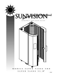
Unpacking and Inspection<br />
Your sunbed comes in two cardboard cartons,<br />
one for the bench and one for the<br />
canopy. Open the cartons and remove the<br />
bench and canopy as follows.<br />
The bench and canopy are each wrapped<br />
in plastic. Pull back the plastic and, with<br />
a helper, grasp the bench and pull it from<br />
the carton bottom, leaving the plastic<br />
wrap and the carton packaging. Do the<br />
same for the canopy. Do not attempt to<br />
lift either unit with the plastic still on as<br />
it may slip.<br />
Note! The cartons are reusable. You may<br />
wish to save them for future use.<br />
As you unpack your boxes you should<br />
find the following:<br />
• Canopy unit<br />
• Bench unit<br />
• Pair of gas springs<br />
• Front skirt panel<br />
• Bag containing necessary assembly<br />
hardware, safety goggles, opening<br />
handle and pillow<br />
• Gas spring cover panel<br />
Inspect these items, including the canopy<br />
and bench, and make sure they are free<br />
from any visible damage. Report the<br />
extent of any damage to the transportation<br />
company.<br />
Record the serial numbers of the canopy<br />
and bench in the area provided at the<br />
back of this manual. This information will<br />
be required whenever you call customer<br />
service.<br />
Tools Required<br />
You will need the following tools to<br />
assemble your sunbed.<br />
Utility Knife<br />
#2 Phillips<br />
Screwdriver<br />
7/16” Wrench<br />
3
4 Installation - pre-installation planning<br />
Pre-Installation Planning<br />
Before you begin to assemble your sunbed, you should observe the following considerations.<br />
WARNING<br />
Shock hazard.<br />
Disconnect power before<br />
servicing.<br />
• The 30 XS-Power requires a dedicated<br />
circuit capable of providing 30 Amp<br />
service at 220VAC. This unit must be<br />
hardwired directly to a junction box.<br />
We recommend connection by a professional<br />
electrician.<br />
• IMPORTANT! Voltage must be below<br />
230V AC or may require a Buck<br />
Booster.<br />
CAUTION<br />
Use of a voltage source above 230V<br />
AC may prevent proper operation of<br />
the sunbed and could cause damage<br />
and void the warranty.<br />
CAUTION<br />
Air from the room is used to cool<br />
the sunbed. Maximum ambient<br />
room temperature should be 80°F.<br />
Place your sunbed no closer than<br />
6” from any wall. Make sure nothing<br />
obstructs the airflow into the<br />
sunbed’s endcaps or out of the fan<br />
openings. A poorly ventilated room<br />
may cause the unit to become hot<br />
and cause discomfort to the user.<br />
CAUTION<br />
Proper assembly of your sunbed<br />
requires three people. Plan to have<br />
a couple of helpers assist you.<br />
27629-01A
27629-01A<br />
Hardware Inventory<br />
Use the utility knife to cut open the hardware<br />
bag. Remove the hardware. Make<br />
sure you have the following items.<br />
Installation - hardware inventory 5<br />
Clevis Pin<br />
3/8” x 2 1/64”<br />
Quantity 2<br />
Bridge Pin<br />
Quantity 4<br />
Clevis Fork,<br />
M10 Long<br />
Quantity 4<br />
Centering Spring<br />
Quantity 4<br />
1/4-20 x 1/2”<br />
Machine Screw<br />
Quantity 8<br />
1/4-20 Locknut<br />
Quantity 8<br />
Nylon Floating<br />
Bearing<br />
Quantity 4<br />
Clevis Pin<br />
5/16” x 2 1/32”<br />
Quantity 2<br />
Retaining Ring<br />
Quantity 2<br />
10mm Clevis Pin<br />
Quantity 2<br />
Bronze Bushing<br />
Quantity 2<br />
#10 x 1/2” Screw,<br />
Blue Head<br />
Quantity 8<br />
#10 x 1” Screw,<br />
Quantity 3<br />
Safety Goggles<br />
Quantity 1
6 Installation - assembly procedures<br />
Assembly Procedures<br />
Lower Clevis Fork Assembly<br />
1. Insert the larger clevis pin (3/8” x 2<br />
1/64”) through the hole directly below<br />
the large hole in one of the stand<br />
uprights, as shown.<br />
2. Slide a centering spring, a clevis fork<br />
and then another centering<br />
spring onto the clevis pin<br />
and insert the pin the<br />
rest of the way<br />
through the upright.<br />
3. Secure the clevis<br />
pin by inserting<br />
the straight portion<br />
of a bridge pin<br />
through the small<br />
hole in the end of<br />
the clevis pin.<br />
4. Repeat for the other<br />
stand upright. Make sure<br />
the clevis forks point upwards<br />
as shown.<br />
BRIDGE PIN<br />
STAND UPRIGHT<br />
CLEVIS PIN<br />
CLEVIS FORK<br />
CENTERING SPRING<br />
27629-01A
27629-01A<br />
Stand Upright Assembly<br />
1. Place the bench approximately where<br />
it will remain, leaving room to work<br />
behind it.<br />
2. Make sure the clevis forks are pointed<br />
up and secure each stand upright to<br />
the rear of the bench pedestals using<br />
four 1/4-20 x 1/2” machine screws<br />
and four locknuts.<br />
LOCKNUT<br />
(others hidden)<br />
Installation - Assembly Procedures 7<br />
STAND UPRIGHT<br />
MACHINE SCREWS
8 Installation - Assembly Procedures<br />
Canopy Installation<br />
1. Place two nylon floating bearings into<br />
each canopy arm.<br />
2. Holding the canopy over the bench,<br />
with the canopy arms inside the stand<br />
uprights, insert clevis pins (5/16” x 2<br />
1/32”) through the uprights and nylon<br />
floating bearings to attach the canopy.<br />
3. Secure the clevis pins by inserting the<br />
straight portion of a bridge pin through<br />
the small hole in the end of the clevis<br />
pin.<br />
27629-01A
27629-01A<br />
Install Gas Springs<br />
1. Have a helper hold the canopy in its<br />
fully open position.<br />
2. Make sure the threaded holes in the<br />
lower clevis forks face up (the large<br />
holes above the clevis forks allow finger<br />
access). Slide the gas springs down<br />
into the stand uprights, piston end up<br />
as shown, and twist the gas springs<br />
into the lower clevis forks until they<br />
are snug.<br />
Installation - Assembly Procedures 9<br />
3. Screw the upper clevis forks onto the<br />
gas springs.<br />
Do not lower the canopy yet!
10 Installation - Assembly Procedures<br />
Attach Gas Springs<br />
1. With the canopy still raised, slip the<br />
bronze bushings into the hole in the<br />
clevis brackets on the underside of the<br />
canopy arms.<br />
2. Line up both clevis forks and carefully<br />
lower the canopy to engage the clevis<br />
forks. Pay special attention when lowering<br />
the canopy that the clevis forks<br />
do not damage the bronze bushings.<br />
Bronze is excellent for smooth pivoting<br />
applications such as this, but<br />
tends to be soft compared to the<br />
steel clevis fork.<br />
3. Lock the clevis forks in place<br />
with the 10mm clevis pins.<br />
4. Secure the clevis pins with the<br />
retaining rings.<br />
NOTE: When this assembly is complete,<br />
lift and lower the canopy a few times to<br />
lubricate the gas springs for optimum performance.<br />
Clevis Bracket<br />
27629-01A
27629-01A<br />
Attach Cover Panels<br />
1. Put the gas spring cover panel in place<br />
and secure with two blue-headed #10<br />
x 1/2” screws in each end. The skirt<br />
installs in the same way.<br />
Installation - Assembly Procedures 11
12 Installation - Assembly Procedures<br />
Attaching Handle to Canopy<br />
1. Install the handle by inserting the three<br />
#10 x 1” Phillips head screws through<br />
the handle and into the predrilled<br />
holes on the canopy.<br />
27629-01A
27629-01A<br />
Electrical Connections<br />
At the rear of the bed, insert canopy plug<br />
(A) into bench socket (B). Connect power<br />
cord (C) as described in Pre-Installation<br />
Planning. Again, a professional electrician<br />
is recommended. The Remote Control<br />
Bypass plug is already installed in one of<br />
the remote control ports as shown. Your<br />
sunbed will not operate without the<br />
Remote Control Bypass plug or a remote<br />
system connected. Remove the protective<br />
film from the acrylic shields. Your equipment<br />
is now ready for use.<br />
Installation - electrical connections 13<br />
NOTE: Your sunbed is designed to accept<br />
an input from a remote control device.<br />
The remote control is optional. If you<br />
plan on using a remote system refer to<br />
Remote Connections.<br />
ATTENTION: Although the Remote<br />
Control Bypass plug provided with your<br />
sunbed will work wherever a T-Max® terminator<br />
is called for in the series, the T-<br />
Max® terminator will not work as a<br />
bypass plug. A bypass plug is needed only<br />
when your sunbed is operated without a<br />
remote system connected.<br />
Remote Control<br />
Bypass plug<br />
Remote Control<br />
Ports
14 Installation - remote connections<br />
Remote Connections<br />
Your sunbed incorporates advanced circuitry<br />
allowing it to connect and communicate with<br />
most remote control systems. If a remote system<br />
is to be used, first determine whether the<br />
remote system is a T-Max® System or a standard<br />
remote system operating with a control<br />
relay. Follow the appropriate instructions for<br />
your system type.<br />
CAUTION<br />
The remote connection is not designed to supply<br />
or accept high voltage, nor can it provide power<br />
to an external timer. The sunbed’s remote interface<br />
circuitry operates on 5 volts, attempting to<br />
connect it to any higher voltages will damage the<br />
sunbed as well as void your warranty.<br />
REMOTE PORTS<br />
WIRED<br />
REMOTE<br />
PORTS (RJ-22)<br />
WIRELESS<br />
REMOTE<br />
PORT (RJ-11)<br />
T-Max® Wireless Remote System<br />
The T-Max® AP-900 eliminates wires in your<br />
salon, allowing easy setup without hiring an<br />
electrician to run wires. It also protects your<br />
investment from damage by isolating each<br />
unit from one another. Your sunbed arrives<br />
“wireless ready”, which means it connects<br />
directly to the T-Max® wireless system.<br />
The T-Max® wireless system is available in<br />
two configurations: AP-900 Retail and AP-900<br />
OEM. The Retail version contains a power<br />
adapter which plugs into a standard 110V<br />
outlet. The OEM version gets power from the<br />
tanning bed through the same RJ-11 cable it<br />
uses to communicate, eliminating the need<br />
for an outlet. <strong>Tanning</strong> beds labelled “wireless<br />
ready” use the AP-900 OEM.<br />
T-Max® Products<br />
The T-Max® remote systems offer the ultimate<br />
in sunbed control, while allowing the tanner<br />
easy straightforward operation. Your sunbed is<br />
configured to directly connect to this system,<br />
including the new wireless remote system.<br />
The circuitry inside your sunbed eliminates Remote System Hook-up Scenarios<br />
the need for the T-Max® 1A or 3A when con- Follow the diagrams on the next page to see<br />
necting to the T-Max® Manager series. Your the many different scenarios for hooking up<br />
sunbed supports the auto addressing feature your salon. If you need further assistance, call<br />
of the latest T-Max® Manager models and the T-Max® directly at (417) 338-5101.<br />
following parameters: 5, 6, 7, 8, 9, 10, 15 and<br />
23. See your T-Max® manual for descriptions<br />
of these parameters and how they function.<br />
27629-01A
27629-01A<br />
Scenario 1 - T-Max® Manager Series with wires<br />
This system is ideal for multiple sunbed installations.<br />
Simply connect the RJ-22 modular<br />
cable(s), described in the T-Max®<br />
Manager manual, into the remote port(s)<br />
located on the back of your sunbed and follow the<br />
instructions that came with your remote system. If<br />
you have an older T-Max® Manager that doesn’t<br />
support auto addressing, set the address of each<br />
sunbed manually as described in Setting the<br />
address manually. You can place your sunbed at<br />
any location in the series.<br />
Scenario 2 - Single <strong>Bed</strong> wired to T-Max® 3A<br />
In single sunbed installations, the T-Max® 1A and<br />
3A can offer the same control as the T-Max®<br />
Manager, eliminating the need for a Manager. If<br />
you’re using a 1A in this manner, it must have a<br />
chip labelled “master” installed on its circuit<br />
board. The remote control bypass plug must not be<br />
used in this configuration. The 3A may be used as<br />
a “master” with no modification.<br />
Scenario 3 - T-Max® Manager<br />
Series with Complete Wireless<br />
Connect one AP-900 Retail to the<br />
Manager and one AP-900 OEM<br />
to each of the tanning beds.<br />
Install as many beds as you like<br />
with this configuration. Units that<br />
do not communicate with T-Max<br />
will need an AP-900 Retail and<br />
an additional 3A to operate.<br />
Installation - remote connections 15<br />
After you have set the T-Max® 1A’s, or 3A’s, address<br />
to “0” (refer to your T-Max® user’s guide) and the<br />
sunbed’s address to “1”, simply connect the RJ-22<br />
modular cables, described in the T-Max® user’s<br />
guide, directly into either of the smaller ports located<br />
on the back of the sunbed and either port on the<br />
back of the T-Max® 1A or 3A.<br />
NOTE: A T-Max® 1A with a<br />
“master” chip can be substituted<br />
for a 3A.
16 Installation - remote connections<br />
Scenario 4 - T-Max® Manager<br />
Series with Wireless combo<br />
Connect one AP-900 Retail to the<br />
Manager and one AP-900 OEM to<br />
a wireless ready tanning bed. The rest of the<br />
salon may be “daisy-chained” together and connected<br />
to the wireless equipped tanning bed,<br />
eliminating the need to wire the Manager to<br />
the tanning beds.<br />
Scenario 5 - T-Max® Manager Series with<br />
Wireless combo 2<br />
Wireless can be easily added to an existing<br />
salon already utilizing T-Max®. Connect one<br />
AP-900 Retail to the Manager and one AP-<br />
900 OEM to each wireless ready tanning<br />
bed. The rest of the salon may be “daisychained”<br />
together and connected to the<br />
Manager.<br />
Scenario 6 - T-Max 3A with Wireless<br />
Connect one AP-900 Retail to the T-Max® 3A and<br />
one AP-900 OEM to the tanning bed in single bed<br />
installations.<br />
27629-01A
27629-01A<br />
Scenario 7 - Non T-Max® Remote System wired<br />
to unit<br />
Most non-T-Max® remote systems control the<br />
sunbed by the use of a relay. The relay operates<br />
the sunbed by connecting and disconnecting a<br />
pair of wires leading from the sunbed. Refer to the<br />
user’s manual provided with your remote system<br />
to determine if it operates in this way. To connect<br />
your sunbed to this type of system a remote interface<br />
kit is required. Contact your place of purchase<br />
to obtain the kit. The illustration below details a<br />
typical connection. Follow the instructions provided<br />
with the kit and from the remote’s manual to<br />
make the necessary connections.<br />
CAUTION<br />
The remote connection is not designed to supply<br />
or accept high voltage, nor can it provide power<br />
to an external timer. The sunbed’s remote interface<br />
circuitry operates on 5 volts, attempting to<br />
connect it to any higher voltages will damage the<br />
sunbed as well as void your warranty.<br />
Installation - remote connections 17<br />
Setting the sunbed address manually<br />
Before connecting your sunbed to the T-Max®<br />
Manager or T-Max® 1A or 3A, the address of<br />
your sunbed must first be set. Set the “id” manually<br />
as described below.<br />
Setting the “id”<br />
1. Make sure no cables are plugged into<br />
your sunbed’s remote ports.<br />
2. Remove and reapply power to the unit.<br />
3. Press and hold the stop button, located<br />
on the sunbed display, for three seconds<br />
and release. The display should indicate<br />
an “id” number from “oF” to “252”.<br />
1-99<br />
100-199<br />
200-252<br />
4. If you are using a T-Max® 1A or 3A as a<br />
“master” remote, the “id” of the sunbed<br />
must be set to “1”. If you are using a T-<br />
Max® Manager each sunbed must be<br />
assigned a different “id”. To set the “id”<br />
press the timer button, to count up, or<br />
the body fan control button, to count<br />
down, until the desired number is<br />
achieved.<br />
5. Press the stop button to return to the<br />
normal display mode.
18<br />
operation<br />
Before You Tan<br />
Before using your sunbed, please note the<br />
following important precautions.<br />
• Your skin should be free of cosmetics,<br />
tanning oils, or other body lotions<br />
prior to tanning except for those<br />
specifically made for use with tanning<br />
devices. However, do not remove natural<br />
body oils by bathing or showering<br />
immediately before tanning.<br />
• Your hair should be free of gels,<br />
mousses, sprays, or other hair products<br />
prior to tanning. These products can<br />
cause damage to the sunbed acrylic.<br />
As an alternative, a shower cap or<br />
towel can be worn to keep treated hair<br />
away from the sunbed surfaces.<br />
• This unit intended for individual use.<br />
Only one pair of eyewear is included.<br />
DANGER<br />
Some medication may increase your sensitivity<br />
to ultraviolet light. It is recommended<br />
that you consult a physician before using<br />
this sunbed if taking any medication or if you<br />
suspect that your skin might be especially<br />
sensitive to sunlight.<br />
DANGER<br />
Shock hazard.<br />
Do not operate this device near<br />
water or while you are wet.<br />
Exposure Times<br />
Follow the guidelines for skin type and<br />
exposure times as shown in the table<br />
below. Untanned persons should not tan<br />
on consecutive days during their first week<br />
of tanning. Never tan more than once a<br />
day. <strong>Tanning</strong> normally appears after the first<br />
few sessions and maximizes after approximately<br />
four weeks. Tan once or twice per<br />
week thereafter to maintain appearance.<br />
Persons already having a base tan may<br />
begin at advanced levels corresponding to<br />
the extent of their base tan.<br />
RECOMMENDED EXPOSURE TIMES IN MINUTES MAXIMUM EXPOSURE TIME IS 14 MINUTES<br />
Skin Type:<br />
Level 1/Week 1<br />
1st-3rd Sessions Level 2 Level 3 Level 4<br />
Subsequent<br />
Maximum<br />
I Sensitive Skin (Burns easily and severely and does not tan.) NOT RECOMMENDED FOR TANNING<br />
II Light (Burns easily and severely and tans minimally.) 2 5 8 11 14<br />
III Normal (Burns moderately and tans average.) 3 6 10 14 14<br />
IV Dark (Burns minimally, tans easily and above average.) 4 8 11 14 14<br />
27629-01A
27629-01A<br />
Using Your Sunbed<br />
When connected to the T-Max® Manager or T-Max® 1A or 3A.<br />
A Face tanner control - Turns face tanners<br />
on and off during use. Face tanner<br />
lamps require one minute to relight.<br />
(Units equipped with face tanner only)<br />
B Body tanner control - Turns body lamps<br />
on and off during use. (Units equipped<br />
with face tanner only)<br />
C Body fan control - Controls the speed of<br />
the body fan during use.<br />
D Body fan speed indicator - Indicates<br />
speed of fan. (OFF - LOW - MED - HI)<br />
E Timer display - Displays remaining time.<br />
F Stop button - Interrupts tanning session.<br />
G Timer button - Turns bed on. Timer display<br />
shows remaining time.<br />
operation - using your sunbed 19<br />
A B C D E F G<br />
WARNING<br />
Wear protective eyewear.<br />
Failure to may result in severe burns or<br />
longterm injury to the eyes.<br />
1. Lift the canopy, lie down on the bench<br />
(face up), lower the canopy toward your<br />
body using the canopy handle. See Safety<br />
Information for positioning instructions.<br />
2. Put on your safety goggles.<br />
3. Assuming the remote system has been set<br />
to allow a pre-tanning delay time, the timer<br />
display (E) will repeatedly flash the delay<br />
symbol “dL” and then the remaining delay<br />
time. Press the timer button (G) or wait<br />
until the delay time has expired to begin<br />
the tanning session. The lamps will turn on<br />
and the timer will begin to count down.<br />
4. When the timer reaches 0 the lamps turn<br />
off. If you want to stop your session before<br />
time expires, press the stop button (F).<br />
5. Raise the canopy by using the outer edge,<br />
do not push up on the acrylic shield. The<br />
cooling fans run for a period of time after<br />
the lamps shut off to aid in cooling the<br />
sunbed. The timer will indicate “..” as a<br />
reminder to clean the sunbed. After the<br />
sunbed is cleaned press the timer button<br />
and the display will return to “0”.
20 operation - using your sunbed<br />
Using Your Sunbed<br />
When used as a stand alone unit or when connected to a remote system using a control relay.<br />
A B C D E F G<br />
A Face tanner control - Turns face tanners<br />
on and off during use. Face tanner<br />
lamps require one minute to relight.<br />
(Units equipped with face tanner only)<br />
B Body tanner control - Turns body lamps<br />
on and off during use. (Units equipped<br />
with face tanner only)<br />
C Body fan control - Controls the speed of<br />
the body fan during use.<br />
D Body fan speed indicator - Indicates<br />
speed of fan. (OFF - LOW - MED - HI)<br />
E Timer display - Displays remaining time.<br />
F Stop button - Stops tanning session.<br />
G Timer button - Turns bed on. Timer display<br />
shows remaining time. If a lesser<br />
time is desired, press timer button until<br />
desired time is displayed.<br />
WARNING<br />
Wear protective eyewear.<br />
Failure to may result in severe burns or<br />
longterm injury to the eyes.<br />
1. Lift the canopy, lie down on the bench<br />
(face up), lower the canopy toward your<br />
body using the canopy handle. See Safety<br />
Information for positioning instructions.<br />
2. Put on your safety goggles.<br />
3. Press the timer button (G) to begin the tanning<br />
session. The lamps will turn on and<br />
the timer will begin to count down.<br />
4. If a tanning time less than the displayed<br />
time is desired repeatedly press the timer<br />
button (G) to decrease the remaining time.<br />
5. When the timer reaches 0 the lamps turn<br />
off. If you want to stop your session before<br />
time expires, press the stop button (F). You<br />
will have ten seconds to restart with the<br />
remaining time, otherwise the timer will<br />
reset to 0.<br />
6. Raise the canopy by using the outer edge<br />
of the canopy, do not push up on the<br />
acrylic shield. The cooling fans run for a<br />
period of time after the lamps shut off to<br />
aid in cooling the sunbed.<br />
27629-01A
27629-01A<br />
care and maintenance<br />
Cleaning After Use<br />
Clean and disinfect your tanning bed’s<br />
bench and canopy after each use. Use a<br />
non-abrasive disinfectant cleaner that does<br />
not contain ammonia or ammonia derivatives.<br />
Ammonia may damage the acrylic<br />
shield. Spray the acrylic lightly with disinfectant<br />
and wipe dry with a clean soft cloth.<br />
We recommend Australian Gold® pH<br />
Neutral Disinfectant Cleaner.<br />
Thorough Periodic Cleaning<br />
Introduction<br />
The cooling fans draw air through the bed<br />
and over time will cause a dust buildup on<br />
the lamps and reflectors. This will reduce<br />
the tanning effectiveness of the bed. When<br />
a dust buildup is observed, it is necessary to<br />
thoroughly clean the inside of the bench<br />
and canopy.<br />
WARNING<br />
Shock hazard.<br />
Disconnect power before removing<br />
any protective covers.<br />
Cleaning the Canopy and Bench<br />
Step 1 Remove the acrylic shields and<br />
lamps as described in Lamp and<br />
Acrylic Replacement.<br />
21<br />
Step 2 With a soft cloth, wipe the entire<br />
length of each lamp to remove<br />
any film buildup.<br />
Step 3 Clean both sides of the acrylic<br />
shields with a non-ammonia disinfectant<br />
cleaner.<br />
Step 4 Wipe the reflectors with a clean<br />
damp cloth.<br />
Step 5 Re-install the lamps and acrylic<br />
shields.<br />
Mechanical Inspection<br />
Your tanning bed has been built for years of<br />
service. To ensure trouble-free operation<br />
throughout its life, inspect the unit’s<br />
mechanical integrity every 400-500 hours<br />
of use.<br />
• Inspect the unit’s fasteners verifying<br />
that all are firmly in place.<br />
• Inspect gas springs for signs of wear.<br />
Gas springs that will not hold the<br />
canopy in the full open position when<br />
raised should be immediately replaced.<br />
See Troubleshooting.<br />
• Inspect the AC power cord and its<br />
connections.<br />
• Inspect the acrylic. Broken, cracked or<br />
badly scratched acrylics should be<br />
immediately replaced.
22 care and maintenance - replacing lamps<br />
Replacing Lamps<br />
Introduction<br />
To be assured of maximum tanning effectiveness,<br />
change lamps after approximately<br />
800-1000 hours of use. <strong>Tanning</strong> will<br />
continue after this time but at a slower<br />
rate. To ensure trouble-free operation of<br />
your sunbed, replace the lamp starters<br />
whenever the lamps are replaced.<br />
WARNING<br />
Shock hazard.<br />
Disconnect power before servicing.<br />
Removing/Replacing Acrylic Shield<br />
The acrylic shield in the bench and<br />
canopy are secured in place by hinged<br />
profiles which run the length of the bed,<br />
both front and back. Simply pry up on the<br />
inside edge of the profile, starting at the<br />
center of the bed, until it releases its latching<br />
action (see figure at right). Continue to<br />
pry up the profile across its entire length<br />
until it swings back freely. Repeat for the<br />
other profile. The long edges of the acrylic<br />
shields are now exposed.<br />
Standing at the front of the unit, lift the<br />
exposed edge of the acrylic slightly and<br />
carefully begin sliding it toward you until<br />
it is removed from the sunbed. This might<br />
be easier with the help of another person.<br />
After changing the lamps, replace the<br />
acrylic shield by carefully aligning it with<br />
the channels on the ends of the sunbed<br />
and sliding it into place. Close the hinged<br />
profile by pushing it back into place until<br />
it snaps tight.<br />
CAUTION<br />
Be careful. The edges of the acrylic shield<br />
may be sharp.<br />
27629-01A
27629-01A<br />
care and maintenance - replacing lamps 23<br />
Removing/Replacing Lamps<br />
After removing the acrylic shield, replace<br />
lamps as follows.<br />
Step 1 Grasp the lamp at one end and<br />
at the middle and turn the lamp<br />
one quarter turn. Gently remove<br />
the lamp from its holders.<br />
Step 2 Reinstall the lamp by inserting<br />
the pins located on the ends of<br />
the lamp into the slots on top of<br />
the lamp holders and turn the<br />
lamp a quarter turn. It should<br />
click in place.<br />
Recommended Replacement Lamps<br />
We recommend using the lamps specified<br />
below. Use of uncertified lamps is a violation<br />
of Federal regulations and will void<br />
your warranty. These lamps have an average<br />
life of 800-1000 hours of effective<br />
tanning use. Lamps used longer than that<br />
begin to lose their effectiveness even<br />
though they continue to light.<br />
Recommended Replacement Acrylics<br />
Acrylics vary greatly over time in their<br />
ability to effectively transmit UV light.<br />
Acrylics sold by ETS have been life tested<br />
to ensure proper transmission throughout<br />
their useful life.<br />
ONLY THE FOLLOWING LAMPS HAVE BEEN CERTIFIED FOR USE IN THIS EQUIPMENT:<br />
X-Power Wolff® Model XP71-T12-100W BI PIN<br />
XS-Power Wolff® Model XSP71-T12-100W BI-PIN<br />
XS-Power Dual Twister Voltarc® Model XSPDT71-T12-100W BI PIN
24<br />
troubleshooting<br />
Sunbed not tanning<br />
Problem Solution<br />
Lamps fail to light and timer display<br />
is blank<br />
One or more lamps fail to light<br />
The canopy will not stay up<br />
The last minute of tanning time<br />
does not count down from 59 seconds,<br />
but some time less than 59<br />
seconds<br />
I forgot what address, or “id”, I set<br />
my sunbed to<br />
1. Clean sunbed, see Thorough Periodic Cleaning.<br />
2. Ensure supply voltage is between 208 and 230V AC.<br />
3. Replace lamps if lamp hours are greater than 800hrs.<br />
4. Replace acrylic.<br />
1. Make sure the unit is connected to a power source.<br />
2. Check source of AC power. Reset circuit breaker or replace fuse.<br />
1. Check that lamp is installed correctly.<br />
2. Switch unlit lamp with a lamp that lights, if new lamp lights<br />
and old lamp still does not, replace old lamp.<br />
NOTE: Gas springs are manufactured to hold the canopy in its<br />
fully open position as well as allow it to rest fully closed. If left<br />
open for an extended period of time some creep down may<br />
occur. This is considered normal. Keep the unit closed when<br />
not in use. If the canopy will not stay fully open when raised...<br />
1. Raise and lower the canopy a few times to lubricate gas spring<br />
internal seals.<br />
2. Replace gas springs.<br />
If the timer button has been pressed to decrease tanning time<br />
during the session, the time expired in the current minute is<br />
subtracted from the last minute.<br />
By holding the body fan button for 3 seconds the timer display<br />
will briefly display three numbers; the installed timer software<br />
version, a factory set timer code and then the sunbed’s “id”<br />
number.<br />
27629-01A
27629-01A<br />
Problem Solution<br />
Timer display is indicating Er 91<br />
Timer display is indicating Er 92<br />
Timer display is indicating Er 93<br />
Timer display is indicating Er 94<br />
Timer display changes to indicate<br />
a tanning time after the timer button<br />
is pressed but lamps do not<br />
come on<br />
My bed is connected to the T-<br />
Max® Manager remote system<br />
and when the delay time has<br />
expired the timer display starts<br />
counting down but the bed lights<br />
do not come on<br />
My bed won’t work with the T-<br />
Max® Manager remote system<br />
Timer display continues to show a<br />
0 after the timer button is pressed<br />
troubleshooting 25<br />
Timer software error. Disconnect and reapply power to the unit.<br />
Current sensor indicating unit is off when it should be on.<br />
Contact servicer.<br />
Current sensor indicating unit is on when it should be off.<br />
Contact servicer.<br />
Requested session time exceeds maximum time allowed.<br />
1. Bypass plug is not installed, see Electrical Connections.<br />
2. A non-SunStar® bypass has been used. See Electrical<br />
Connections.<br />
3. If remote is being used, other than T-Max® Manager, the external<br />
timer may not be activated.<br />
4. Remote wiring is incorrect, see the instructions provided with<br />
the remote interface kit.<br />
The auto start feature of the remote system is disabled, see the<br />
instructions provided with your remote system.<br />
1. The sunbed must first be set to a unique address, see Remote<br />
Connections.<br />
2. The bypass or terminator plug may be installed in the series in<br />
an inappropriate location. Plug the bypass plug only into the<br />
bed at the end of the series.<br />
1. T-Max® Manager remote system has not yet been set.<br />
2. Sunbed address is not set correctly, see Remote Connections.
26 troubleshooting<br />
Problem Solution<br />
My bed is connected to a T-Max®<br />
remote system but I am having<br />
trouble getting into “id” mode<br />
My bed, connected to a T-Max®<br />
Manager, did not display “dL” but<br />
does indicate:<br />
“0”<br />
a tanning time and the lamps<br />
have come on<br />
a tanning time but the lamps<br />
have not come on<br />
When auto-addressing the first bed<br />
does not register an “id”<br />
When using a T-Max® 1A my<br />
sunbed won’t function properly<br />
My salon suffers frequent, short<br />
power outages and clients complain<br />
about losing session time<br />
You have probably attempted to connect your sunbed to the<br />
remote system already. Disconnect the remote plug(s) from the<br />
ports at the back of the sunbed, wait 90 seconds and try again.<br />
1. Remote device has not been set.<br />
2. The sunbed has not been connected to the remote system, see<br />
Remote Connections.<br />
1. Delay time of T-Max® Manager has not been set.<br />
2. Delay time has expired and session has begun.<br />
Auto start function of T-Max® Manager has been turned off.<br />
Press the timer button to turn on lamps.<br />
When using the auto address feature of the T-Max® Manager<br />
you must wait 10 seconds from the time you start the auto<br />
address function before addressing the first bed.<br />
SunStar® Bypass plugs or terminator plugs may be needed if<br />
the T-Max® 1A and the sunbed are over 100 feet apart. Install<br />
the plugs in the open remote port in the sunbed and the T-<br />
Max® 1A.<br />
If you have a T-Max® Manager, changing parameter 23 from<br />
“0” to “1” will allow the tanning bed to remember how much<br />
time was left when power goes out and resume its session<br />
after power is restored. Consult your T-Max® Manager manual<br />
for information on setting parameters.<br />
27629-01A
27629-01A<br />
scheduled maintenance 27<br />
What to do Each use Monthly<br />
WHEN<br />
400-<br />
500hrs<br />
800-<br />
1000hrs As Needed<br />
A. Clean/Disinfect Acrylic Surfaces* ✘<br />
B. Clean Lamps* ✘<br />
C. Clean Reflectors* ✘<br />
D. Clean Exterior ✘<br />
E. Check/Clean Fans† ✘<br />
F. Change Lamps and Starters** ✘<br />
G. Change Acrylics** ✘<br />
H. Check Fasteners (nuts, bolts, etc.)* ✘<br />
I. Check Power Cords* ✘<br />
* See Care and Maintenance<br />
** See Lamp and Acrylic Replacement<br />
† Fans are located on the top and bottom of the unit, near the center. Use a vacuum to clean.<br />
MAINTENANCE LOG<br />
What When What When What When<br />
example B C D 4/15
R-30XSP<br />
27629-01A
27629-01A<br />
<strong>Parts</strong> List<br />
This is a list of parts which may be replaced by the<br />
consumer. Care should be taken when replacing<br />
anything related to electrical wiring. We recommend<br />
contacting a professional electrician. When<br />
calling for parts, first state your bed model as R-<br />
30XSP or R-30XSPD. Then refer to this list and preceding<br />
illustration for proper part identification.<br />
Acrylic, Bench<br />
Acrylic, Canopy*<br />
Ballast, 100W<br />
Bushing, Bronze 10mm*<br />
Body Fan Kit* (optional)<br />
Canopy Mounting Arm<br />
Capacitor, 75uF<br />
Contactor<br />
Cover, Bench<br />
Cover, Canopy<br />
Endcap, Kit (with inserts)<br />
Fan<br />
Gas Spring Cover Panel*<br />
Gas Springs*<br />
Handle<br />
Hardware Kit*<br />
Hour Counter*<br />
* Not shown<br />
Keypad Assy Kit<br />
Lamp Holder w/ Starter Holder<br />
Lamp Holder w/o Starter<br />
Lamps*<br />
Manual*<br />
Pillow*<br />
Profile (blank)<br />
Remote Connection PCB<br />
Remote Control Bypass Plug*<br />
Schematic Packet*<br />
Silk-screened Profile (Warnings)<br />
Skirt<br />
Starter, K-12<br />
Timer<br />
Trim Profile (grey)<br />
Wiring Harness, Keypad to Timer<br />
Wiring Harness, Remote PCB to Timer<br />
Record this information for ease of service:<br />
Date of purchase:<br />
Bench serial number:<br />
Canopy serial number:
Size<br />
30 XS-Power<br />
Weight (Pounds) 469<br />
Minimum Room Size 7’ x 9’<br />
Electrical -<br />
Voltage (AC) 220<br />
Amperage 17<br />
Circuit Breaker (Amps) 30<br />
Outlet Hardwire<br />
Main Lamps XS-Power 100W<br />
Ballasts 100W<br />
Cooling System 230cfm “Turbo”(optional)<br />
Timer System Digital<br />
Max. Exposure Time 14 minutes<br />
Back-up Timer Digital “Watchdog” Circuitry<br />
Remote Capability T-Max® compatible<br />
27629-01A