- Page 1 and 2:
© Siemens AG 2009 Controls - Conta
- Page 3 and 4:
S3 3RT1. 4 Controls — Contactors
- Page 5 and 6:
■ Overview 3RT1 contactors and co
- Page 7 and 8:
3RT1 contactors Sizes S6 to S12 wit
- Page 9 and 10:
3RA1 contactor assemblies, 3RT1 con
- Page 11 and 12:
■ Overview 3RT10 contactors, 3-po
- Page 13 and 14:
3RT1. . .-.P version: For 24 V DC P
- Page 15 and 16:
■ Integration Auxiliary switch bl
- Page 17 and 18:
■ Technical specifications SIRIUS
- Page 19 and 20:
Endurance of the main contacts Size
- Page 21 and 22:
1) The OFF-delay of the NO contact
- Page 23 and 24:
For tools for opening Cage Clamp te
- Page 25 and 26:
1) The OFF-delay of the NO contact
- Page 27 and 28:
3RT, 3TB, 3TF Contactors for Switch
- Page 29 and 30:
1) Test conditions according to IEC
- Page 31 and 32:
3RT, 3TB, 3TF Contactors for Switch
- Page 33 and 34:
1) For endurance of the main contac
- Page 35 and 36:
1) Depending on the electronic ball
- Page 37 and 38:
For tools for opening Cage Clamp te
- Page 39 and 40:
© Siemens AG 2009 3RT, 3TB, 3TF Co
- Page 41 and 42:
3RT, 3TB, 3TF Contactors for Switch
- Page 43 and 44:
1) For endurance of the main contac
- Page 45 and 46:
1) Industrial furnaces and electric
- Page 47 and 48:
For tools for opening Cage Clamp te
- Page 49 and 50:
© Siemens AG 2009 3RT, 3TB, 3TF Co
- Page 51 and 52:
© Siemens AG 2009 3RT, 3TB, 3TF Co
- Page 53 and 54:
1) For more information about short
- Page 55 and 56:
■ Overview 3RT12 vacuum contactor
- Page 57 and 58:
1) Test conditions according to IEC
- Page 59 and 60:
1) When connecting cable lugs accor
- Page 61 and 62:
1) Industrial furnaces and electric
- Page 63 and 64:
1) When connecting cable lugs to DI
- Page 65 and 66:
■ Technical specifications 3RT, 3
- Page 67 and 68:
1) To easily replace the laterally
- Page 69 and 70:
1) Max. permissible rated operation
- Page 71 and 72:
■ Overview 3TB5 contactors with D
- Page 73 and 74:
3RT, 3TB, 3TF Contactors for Switch
- Page 75 and 76:
3RT, 3TB, 3TF Contactors for Switch
- Page 77 and 78:
■ Technical specifications Contac
- Page 79 and 80:
1) Applies to 50/60 Hz coil: At 50
- Page 81 and 82:
© Siemens AG 2009 3RT, 3TB, 3TF Co
- Page 83 and 84:
3RT, 3TB, 3TF Contactors for Switch
- Page 85 and 86:
■ Function The operating times of
- Page 87 and 88:
Components for customer assembly As
- Page 89 and 90:
Starter Sizes S..-S..-S.. Type 3RA.
- Page 91 and 92:
3TD, 3TE Contactor Assemblies 3TE6
- Page 93 and 94:
3RT, 3RH, 3TB, 3TC, 3TH, 3TK Contac
- Page 95 and 96:
3RT, 3RH, 3TB, 3TC, 3TH, 3TK Contac
- Page 97 and 98:
3RT, 3RH, 3TB, 3TC, 3TH, 3TK Contac
- Page 99 and 100:
3RT, 3RH, 3TB, 3TC, 3TH, 3TK Contac
- Page 101 and 102:
3RT, 3RH, 3TB, 3TC, 3TH, 3TK Contac
- Page 103 and 104:
3RT, 3RH, 3TB, 3TC, 3TH, 3TK Contac
- Page 105 and 106:
3RT, 3RH, 3TB, 3TC, 3TH, 3TK Contac
- Page 107 and 108:
3RT, 3RH, 3TB, 3TC, 3TH, 3TK Contac
- Page 109 and 110:
3RT, 3RH, 3TB, 3TC, 3TH, 3TK Contac
- Page 111 and 112:
3RT, 3RH, 3TB, 3TC, 3TH, 3TK Contac
- Page 113 and 114:
3RT, 3RH, 3TB, 3TC, 3TH, 3TK Contac
- Page 115 and 116:
3RT, 3RH, 3TB, 3TC, 3TH, 3TK Contac
- Page 117 and 118:
3RT, 3RH, 3TB, 3TC, 3TH, 3TK Contac
- Page 119 and 120:
3RT, 3RH, 3TB, 3TC, 3TH, 3TK Contac
- Page 121 and 122:
3RT, 3RH, 3TB, 3TC, 3TH, 3TK Contac
- Page 123 and 124:
3RT, 3RH, 3TB, 3TC, 3TH, 3TK Contac
- Page 125 and 126:
3RT, 3RH, 3TB, 3TC, 3TH, 3TK Contac
- Page 127 and 128:
3RT, 3RH, 3TB, 3TC, 3TH, 3TK Contac
- Page 129 and 130: 3RT, 3RH, 3TB, 3TC, 3TH, 3TK Contac
- Page 131 and 132: ■ Function Contact reliability Hi
- Page 133 and 134: For corresponding 8WA2 803/8WA2 804
- Page 135 and 136: Contactors Type 3RH1. Size S00 Load
- Page 137 and 138: ■ Overview AC and DC operation IE
- Page 139 and 140: Contactors Control Magnetic coil op
- Page 141 and 142: ■ Overview AC and DC operation IE
- Page 143 and 144: Contactor relays Short-circuit prot
- Page 145 and 146: 3RH, 3TH Contactor Relays 3RH11 cou
- Page 147 and 148: All technical specifications not me
- Page 149 and 150: 1) Capacitive loads can result in m
- Page 151 and 152: 1) Capacitive loads can result in m
- Page 153 and 154: ■ Design Installation instruction
- Page 155 and 156: Type General data 3TX7 004/3TX7 005
- Page 157 and 158: ■ Overview The new 3RS18 coupling
- Page 159 and 160: ■ Overview The LZX complete units
- Page 161 and 162: ■ Technical specifications Relay
- Page 163 and 164: ■ More information Notes on confi
- Page 165 and 166: ■ Technical specifications 1) If
- Page 167 and 168: ■ Overview Snap-on auxiliary swit
- Page 169 and 170: Additional load module Size S00 for
- Page 171 and 172: ✓ Function is possible. Accessori
- Page 173 and 174: Contactors Type 3RT19 26-2P. Pneuma
- Page 175 and 176: © Siemens AG 2009 DC-12 - At 24 V
- Page 177 and 178: ■ Technical specifications For 3T
- Page 179: ■ Dimensional drawings 3RT10 cont
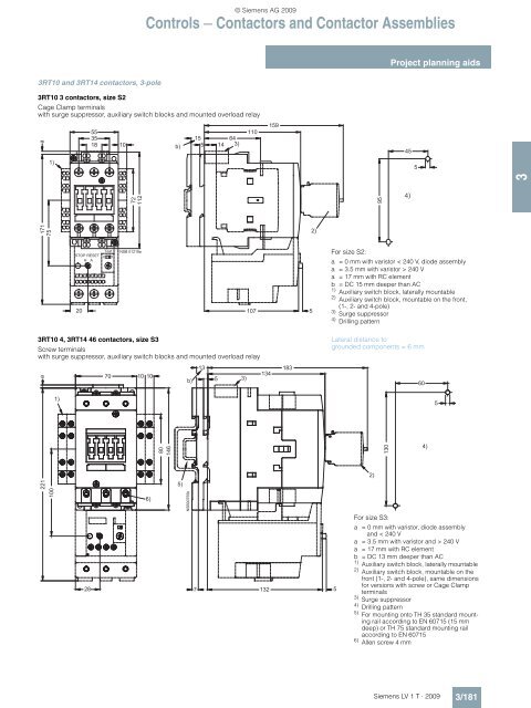
- Page 183 and 184: 3RT10 and 3RT14 contactors, 3-pole
- Page 185 and 186: 3RT12 vacuum contactors, 3-pole 3RT
- Page 187 and 188: 3RT16 capacitor contactors 3RT16 17
- Page 189 and 190: Contactors with extended operating
- Page 191 and 192: 3RH11 and 3RH14 contactor relays 3R
- Page 193 and 194: Accessories for 3RT1 contactors 3RT
- Page 195 and 196: Accessories for 3RT1 contactors 3RT
- Page 197 and 198: Accessories for 3RT1 contactors 3RH
- Page 199 and 200: Accessories for 3RA1 contactor asse
- Page 201 and 202: 3RA13 reversing contactor assemblie
- Page 203 and 204: 3RA14 contactor assemblies for wye-
- Page 205 and 206: 3TF68 and 3TF69 vacuum contactors,
- Page 207 and 208: 3TB5 contactors 3TB50 and 3TB52 con
- Page 209 and 210: Accessories for 3TK1 contactors 3TK
- Page 211 and 212: 3TC7 contactors 3TC74 contactors Si
- Page 213 and 214: 3TF2 contactors for switching motor
- Page 215 and 216: 3TH2 contactor relays, width 45 mm,
- Page 217 and 218: Coupling relays with narrow design
- Page 219 and 220: LZS:RT relay couplers Complete unit
- Page 221 and 222: ■ Schematics 1) Not for 3RT12 vac
- Page 223 and 224: 1) Not for 3RT12 vacuum contactors.
- Page 225 and 226: Controls — Contactors and Contact
- Page 227 and 228: Controls — Contactors and Contact
- Page 229 and 230: Controls — Contactors and Contact
- Page 231 and 232:
Position of the terminals for 3RT1
- Page 233 and 234:
Controls — Contactors and Contact
- Page 235 and 236:
Position of the terminals for 3RH1
- Page 237 and 238:
Circuit diagrams for 3RA13 reversin
- Page 239 and 240:
Internal circuit diagrams for 3TG10
- Page 241 and 242:
Controls — Contactors and Contact
- Page 243 and 244:
Controls — Contactors and Contact
- Page 245 and 246:
Internal circuit diagrams for 3TF2
- Page 247 and 248:
Controls — Contactors and Contact
- Page 249 and 250:
Semiconductor couplers - connection
- Page 251 and 252:
Plug-in bases with logical isolatio