

Catalog LV1 T 2009 Chapter 3 EN
Catalog LV1 T 2009 Chapter 3 EN
Catalog LV1 T 2009 Chapter 3 EN

Create successful ePaper yourself
Turn your PDF publications into a flip-book with our unique Google optimized e-Paper software.
3RT1. . .-.P version: For 24 V DC PLC output or<br />
PLC relay output, with remaining lifetime indicator (RLT).<br />
A1<br />
-.PP3.<br />
200-277 V<br />
50-60 Hz<br />
DC<br />
A2<br />
H1<br />
H2<br />
R1<br />
R2<br />
IN<br />
IN<br />
ON<br />
RLT<br />
60%<br />
40%<br />
20%<br />
Reset<br />
3RT105/3RT145<br />
300 V<br />
AC/DC<br />
RLT<br />
24 V<br />
DC<br />
Displays for RLT:<br />
LED green<br />
LED green<br />
LED orange<br />
LED red<br />
RLT Reset<br />
Plug-in<br />
connection<br />
7-pole<br />
NSB0_01145b Contactor ON<br />
To supply the solenoid and the remaining lifetime indicator with<br />
power, the control supply voltage Us must be connected to terminals<br />
A1/A2 of the laterally mounted solid-state module. The<br />
control inputs of the contactor are connected to a 7-pole plug-in<br />
connection; the screwless spring-type connection is part of the<br />
scope of supply.<br />
The "Remaining Lifetime RLT" status signal is available at<br />
terminals R1/R2 through a floating relay contact (hard goldplated,<br />
enclosed) and can be input to SIMOCODE, PLC or<br />
other devices for processing, for example.<br />
Permissible current-carrying capacity of the R1/R2 relay output:<br />
- Ie /AC-15/24 to 230 V: 3 A<br />
- Ie /DC-13/24 V: 1 A<br />
LED indications<br />
The following states are indicated by means of LEDs on the<br />
laterally mounted solid-state module:<br />
- Contactor ON (energized state): green LED ("ON")<br />
- Indication of remaining lifetime<br />
2 control options:<br />
Contactor control without a coupling link directly through a<br />
24 V DC/≥ 30 mA PLC output (<strong>EN</strong> 61131-2) by way of terminals<br />
IN+/IN-.<br />
3<br />
A1 A2<br />
H1<br />
H2<br />
R1<br />
R2<br />
IN<br />
IN<br />
NSB0_01146e<br />
S2<br />
S1<br />
S1<br />
1 2<br />
L1/L+<br />
N/L-<br />
Indication<br />
of remaining<br />
lifetime 20%<br />
PLC output<br />
24 V/30 mA DC<br />
Possibility of switching from automatic control to local control by<br />
way of terminals H1/H2, i. e. automatic control through PLC or<br />
SIMOCODE/PROFIBUS DP can be deactivated e. g. at start-up<br />
or in the event of a fault and the contactor can be controlled<br />
manually.<br />
3RT, 3TB, 3TF Contactors for Switching Motors<br />
$ Solid-state module of<br />
3RT1. . .-.P contactor<br />
% Plug-in connection, 7-pole<br />
S1 Selector switch for<br />
switching from automatic<br />
control through PLC<br />
semiconductor output to<br />
local control<br />
S2 Local control option<br />
& Emergency shutdown<br />
– optional<br />
© Siemens AG <strong>2009</strong><br />
3RT10 contactors, 3-pole, 3 ... 250 kW<br />
Contactor control through relay outputs, e. g. by<br />
-PLC<br />
- SIMOCODE<br />
by way of terminals H1/H2. Contact loading: U s/approx. 5 mA.<br />
When operated through SIMOCODE, a communication link to<br />
PROFIBUS DP is also provided.<br />
3<br />
A1 A2<br />
H1<br />
H2<br />
R1<br />
R2<br />
IN<br />
IN<br />
NSB0_01147d<br />
S1<br />
S2<br />
1 2<br />
L1/L+<br />
N/L-<br />
PROFIBUS DP<br />
e.g.<br />
SIMOCODE<br />
PLC<br />
other<br />
Indication<br />
of remaining<br />
lifetime 20%<br />
$ Solid-state module of<br />
3RT1. . .-.P contactor<br />
% Plug-in connection, 7-pole<br />
S1 Selector switch for<br />
switching from automatic<br />
control, for example,<br />
through SIMOCODE or PLC<br />
relay output to local control<br />
S2 Local control option<br />
& Emergency shutdown<br />
– optional<br />
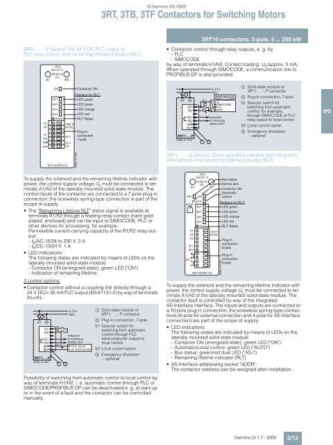
3RT1. . .-.Q version: Communication-capable with integrated<br />
AS-Interface and remaining lifetime indicator (RLT)<br />
AS-i ON<br />
AUTO<br />
ADDR.<br />
RLT<br />
60%<br />
40%<br />
20%<br />
Reset<br />
H1<br />
H2<br />
H3<br />
SF1<br />
SF2<br />
AS-i<br />
A1<br />
-.QP3.<br />
200-277 V<br />
50-60 Hz<br />
DC<br />
A2<br />
3RT105/3RT145<br />
300 V<br />
AC/DC<br />
1<br />
2<br />
3<br />
4<br />
Bus status<br />
Adress jack<br />
Contactor ON<br />
Automatic<br />
control<br />
Displays for RLT:<br />
LED green<br />
LED green<br />
LED orange<br />
LED red<br />
RLT Reset<br />
NSB0_01148c<br />
Plug-in<br />
connection<br />
6-pole<br />
Plug-in<br />
connection<br />
4-pole<br />
To supply the solenoid and the remaining lifetime indicator with<br />
power, the control supply voltage U s must be connected to terminals<br />
A1/A2 of the laterally mounted solid-state module. The<br />
contactor itself is controlled by way of the integrated<br />
AS-Interface interface. The inputs and outputs are connected to<br />
a 10-pole plug-in connection; the screwless spring-type connections<br />
(6-pole for external connection and 4-pole for AS-Interface<br />
connection) are part of the scope of supply.<br />
LED indications<br />
The following states are indicated by means of LEDs on the<br />
laterally mounted solid-state module:<br />
- Contactor ON (energized state): green LED ("ON")<br />
- Automatic/Local control: green LED ("AUTO")<br />
- Bus status: green/red dual LED ("AS-i")<br />
- Remaining lifetime indicator (RLT)<br />
AS-Interface addressing socket "ADDR":<br />
The contactor address can be assigned after installation.<br />
Siemens LV 1 T · <strong>2009</strong><br />
3/13<br />
3


