Datasheet Search Site - http://www.Laogu.com
Datasheet Search Site - http://www.Laogu.com
Datasheet Search Site - http://www.Laogu.com

Create successful ePaper yourself
Turn your PDF publications into a flip-book with our unique Google optimized e-Paper software.
DATA SHEET<br />
SURFACE-MOUNT CERAMIC<br />
MULTILAYER CAPACITORS<br />
Class 2, Y5V<br />
16/25/50 V<br />
Product Specification – Jul 08, 2003 V.7
Phy<strong>com</strong>p Product specification<br />
Surface-mount ceramic<br />
multilayer capacitors<br />
FEATURES<br />
• Five standard sizes<br />
• High capacitance per unit volume<br />
• Supplied in tape on reel<br />
• NiSn terminations.<br />
APPLICATIONS<br />
• Consumer electronics, for<br />
example:<br />
− Tuners<br />
− Television receivers<br />
− Video recorders<br />
− All types of cameras<br />
− Mobile telephones.<br />
DESCRIPTION<br />
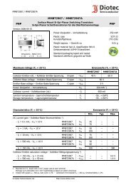
The capacitor consists of a<br />
rectangular block of ceramic<br />
dielectric in which a number of<br />
interleaved metal electrodes are<br />
contained. This structure gives rise<br />
to a high capacitance per unit<br />
volume.<br />
The inner electrodes are connected<br />
to the two terminations and finally<br />
covered with a layer of plated tin<br />
(NiSn). A cross section of the<br />
structure is shown in Fig.1.<br />
QUICK REFERENCE DATA<br />
DESCRIPTION VALUE<br />
Rated voltage UR (DC) 16 V, 25 V, 50 V<br />
Capacitance range (E6 series) 10 nF to 10 µF; note 1<br />
Tolerance on capacitance ±20% (M); −20% to +80% (Z)<br />
Test voltage (DC) for 1 minute: 2.5 × U R<br />
Class 2, Y5V<br />
16/25/50 V<br />
Sectional specifications IEC 60384-10, second edition 1989-04<br />
Detailed specification based on IEC 60384-10-1<br />
End terminations NiSn<br />
Climatic category (IEC 60068) 30/85/21<br />
Note<br />
1. Measured at 25 °C, 1 V and 1 kHz, using a four-gauge method.<br />
electrodes<br />
ceramic material<br />
terminations<br />
2003 Jul 08 Rev.7 2 <strong>www</strong>.yageo.<strong>com</strong><br />
MLB457<br />
Fig.1 Construction of a ceramic multilayer capacitor.
Phy<strong>com</strong>p Product specification<br />
Surface-mount ceramic<br />
multilayer capacitors<br />
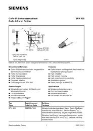
MECHANICAL DATA<br />
For dimensions see Table 1.<br />
Physical dimensions<br />
Table 1 Capacitor dimensions; see Fig.2<br />
T<br />
L2<br />
L4<br />
L1<br />
Class 2, Y5V<br />
16/25/50 V<br />
2003 Jul 08 Rev.7 3 <strong>www</strong>.yageo.<strong>com</strong><br />
L3<br />
Fig.2. Component outline.<br />
CASE SIZE L1 W<br />
MIN.<br />
T<br />
MAX.<br />
L2 and L3 .<br />
MIN. MAX.<br />
L4 MIN.<br />
Dimensions in millimetres<br />
0402 1.0 ±0.05 0.5 ±0.05 0.45 0.55 0.15 0.30 0.40<br />
0603 1.6 ±0.10 0.8 ±0.07 0.73 0.87 0.25 0.65 0.40<br />
0805 2.0 ±0.10 1.25 ±0.10 0.50 1.35 0.25 0.75 0.55<br />
1206 3.2 ±0.15 1.6 ±0.15 0.50 1.75 0.25 0.75 1.40<br />
1210 3.2 ±0.20 2.5 ±0.20 1.40 1.60 0.25 0.75 1.40<br />
Dimensions in inches<br />
0402 0.040 ±0.002 0.020 ±0.002 0.018 0.022 0.008 0.012 0.016<br />
0603 0.063 ±0.004 0.032 ±0.003 0.029 0.035 0.010 0.026 0.016<br />
0805 0.079 ±0.004 0.049 ±0.004 0.020 0.053 0.010 0.030 0.022<br />
1206 0.126 ±0.006 0.063 ±0.006 0.020 0.069 0.010 0.030 0.056<br />
1210 0.126 ±0.008 0.098 ±0.008 0.047 0.069 0.010 0.030 0.056<br />
MBB211<br />
W
Phy<strong>com</strong>p Product specification<br />
Surface-mount ceramic<br />
multilayer capacitors<br />
SELECTION CHART FOR 16 V AND 25 V<br />
C<br />
(nF)<br />
LAST<br />
TWO<br />
DIGITS<br />
OF<br />
12NC<br />
1 23<br />
1.5 25<br />
2.2 27<br />
3.3 29<br />
4.7 32<br />
6.8 34<br />
10 36<br />
15 38<br />
16 V 25 V<br />
Class 2, Y5V<br />
16/25/50 V<br />
0402 0603 0805 1206 1210 0603 0805 1206 1210<br />
22 41 0.8 ±0.07<br />
33 43 0.5 ±0.05<br />
47 45<br />
68 47<br />
100 49 0.6 ±0.1<br />
150 52 0.85 ±0.1<br />
220 54 0.8 ±0.07 0.6 ±0.1<br />
330 56<br />
470 58 0.85 ±0.1 0.85 ±0.1<br />
680 61 1.25 ±0.1<br />
1 000 63 0.85 ±0.1 1.15 ±0.1<br />
1 500 65 1.25 ±0.1<br />
2 200 67<br />
3 300 69 1.15 ±0.1<br />
4 700 72<br />
10 000 76 1.5 ±0.1 1.5 ±0.1<br />
Note<br />
1. Values in shaded cells indicate thickness class in mm.<br />
2003 Jul 08 Rev.7 4 <strong>www</strong>.yageo.<strong>com</strong>
Phy<strong>com</strong>p Product specification<br />
Surface-mount ceramic<br />
multilayer capacitors<br />
SELECTION CHART FOR 50 V<br />
C<br />
(nF)<br />
LAST<br />
TWO<br />
DIGITS<br />
OF<br />
12NC<br />
10 05<br />
15 06<br />
22 07<br />
Class 2, Y5V<br />
16/25/50 V<br />
2003 Jul 08 Rev.7 5 <strong>www</strong>.yageo.<strong>com</strong><br />
50 V<br />
0603 0805 1206<br />
33 08 0.8 ±0.07 0.6 ±0.1<br />
47 09<br />
68 11<br />
100 12<br />
150 13 0.85 ±0.1 0.6 ±0.1<br />
220 14<br />
330 15 1.25 ±0.1<br />
470 16 0.85 ±0.1<br />
680 17<br />
1 000 18 1.15 ±0.1<br />
Note<br />
1. Values in shaded cells indicate thickness class in mm.<br />
Thickness classification and packing quantities<br />
THICKNESS<br />
CLASSIFICATION<br />
(mm)<br />
8 mm TAPE WIDTH QUANTITY PER REEL QUANTITY PER BULK CASE<br />
∅180 mm; 7"<br />
PAPER BLISTER<br />
∅330 mm; 13"<br />
PAPER BLISTER<br />
0402 0603 0805<br />
0.5 ±0.05 10 000 − 50 000 − 50 000 − −<br />
0.6 ±0.10 4 000 − 20 000 − − − 10 000<br />
0.8 ±0.07 4 000 − 15 000 − − 15 000 −<br />
0.85 ±0.10 4 000 − 15 000 − − 15 000 8 000<br />
1.15 ±0.10 − 3 000 − 10 000 − − −<br />
1.25 ±0.10 − 3 000 − 1 000 − − 5 000<br />
1.5 ±0.10 − 3 000 − − − − −
Phy<strong>com</strong>p Product specification<br />
Surface-mount ceramic<br />
multilayer capacitors<br />
ORDERING INFORMATION<br />
Components may be ordered by using either a Phy<strong>com</strong>p’s unique 12NC or simple 15-digit clear text code.<br />
Ordering code 12NC (preferred)<br />
handbook, full pagewidth 2 2 X X X X X X 9 X X X<br />
Carrier type<br />
22<br />
38<br />
54<br />
blister<br />
paper<br />
bulk<br />
Rated voltage - Termination<br />
78<br />
91<br />
58<br />
Size<br />
7<br />
6<br />
0<br />
1<br />
2<br />
16 V; NiSn<br />
25 V; NiSn<br />
50 V; NiSn<br />
0402<br />
0603<br />
0805<br />
1206<br />
1210<br />
CCA620_a<br />
Capacitance value (1)<br />
Tolerance<br />
Class 2, Y5V<br />
16/25/50 V<br />
2003 Jul 08 Rev.7 6 <strong>www</strong>.yageo.<strong>com</strong><br />
7<br />
8<br />
±20%<br />
−20/+80%<br />
Packaging (2)<br />
1<br />
5<br />
4<br />
reel: ∅180 mm; 7"<br />
reel: ∅330 mm; 13"<br />
bulk case<br />
(1) Refer to chapters “Selection chart for 16 V and 25 V” and “Selection chart for 50 V”.<br />
(2) Quantity on reel depends on thickness classification, see section “Thickness classification and packing quantities”.<br />
Phy<strong>com</strong>p Clear text code<br />
EXAMPLE: 12062F105M8BB0D<br />
Size<br />
Code<br />
0402<br />
0603<br />
0805<br />
1206<br />
1210<br />
Temp.<br />
Char.<br />
Capacitance Tol. Vol. Termination Packing Marking Series<br />
2F = Y5V 105 = 1000000<br />
pF; the third digit<br />
signifies the<br />
multiplying factor:<br />
2 = × 100<br />
3 = × 1000<br />
4 = × 10 000<br />
5 = × 100 000<br />
6 = × 1 000 000<br />
M = ±20%<br />
Z = −20% /+80%<br />
7 = 16 V<br />
8 = 25 V<br />
9 = 50 V<br />
B = NiSn 2 = 180 mm; 7" paper<br />
3 = 330 mm; 13" paper<br />
B = 180 mm; 7" blister<br />
F = 330 mm; 13" blister<br />
P = bulk case<br />
0 = no marking<br />
D = BME
Phy<strong>com</strong>p Product specification<br />
Surface-mount ceramic<br />
multilayer capacitors<br />
ELECTRICAL CHARACTERISTICS<br />
Class 2 capacitors; Y5V dielectric; NiSn terminations<br />
Class 2, Y5V<br />
16/25/50 V<br />
Unless otherwise stated all electrical values apply at an ambient temperature of 25 ±1 °C, an atmospheric pressure of<br />
86 to 105 kPa, and a relative humidity of 63 to 67%.<br />
DESCRIPTION VALUE<br />
Capacitance range (E6 series); note 1 10 nF to 10 µF<br />
Tolerance on capacitance after 1000 hours ±20% (M); −20% to +80% (Z)<br />
Tan δ; note 1:<br />
all 25 V and 50 V<br />
25 V<br />
except 0805 ≥ 330 nF; 0603 /100 nF; 1206 /1 µF; 1210 /10 µF ≤5%<br />
sizes 0805 / 330 nF; 0603 / 100 nF; 1206 /1 F<br />
2003 Jul 08 Rev.7 7 <strong>www</strong>.yageo.<strong>com</strong><br />
≤7%<br />
0805 ≥ 470 nF ≤9%<br />
1210 /10 µF ≤12.5%<br />
all 16 V<br />
except 0402; 0603 ≥ 330 nF; 0805 ≥ 1.5 µF; 1206 ≥ 3.3 µF; 1210 /10 µF ≤9%<br />
sizes 0402; 0603 ≥ 330 nF; 0805 ≥ 1.5 µF; 1206 ≥ 3.3 µF; 1210 /10 µF ≤12.5%<br />
Insulation resistance after 1 minute at U R (DC):<br />
Maximum capacitance change with respect to capacitance at 25 °C<br />
(for typical values see Fig.5)<br />
R ins >10 GΩ or R ins × C ≥500 seconds<br />
whichever is less<br />
+22% to −82%<br />
Ageing typical 7% per time decade<br />
Resistance to soldering heat 260 °C; 10 seconds<br />
Note<br />
1. Measured at 25 °C, 1 V, 1 kHz, using a four-gauge method.
Phy<strong>com</strong>p Product specification<br />
Surface-mount ceramic<br />
multilayer capacitors<br />
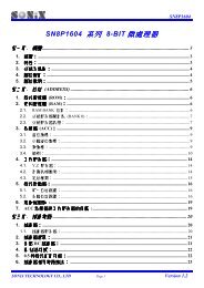
∆C<br />
C<br />
(%)<br />
0<br />
20<br />
40<br />
60<br />
80<br />
MBD076<br />
100<br />
0 10 20 30 40 50<br />
V<br />
DC<br />
(V)<br />
Fig.3 Typical capacitance change with respect to<br />
the capacitance at 1 V as a function of<br />
DC voltage at 25 °C.<br />
25<br />
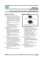
∆ C<br />
C<br />
(%)<br />
0<br />
25<br />
50<br />
75<br />
MBD077<br />
100<br />
25 0 25 50 75 100<br />
T (<br />
o<br />
C)<br />
Fig.5 Typical capacitance change<br />
as a function of temperature.<br />
Class 2, Y5V<br />
16/25/50 V<br />
0<br />
25 0 25 50 75 100<br />
o<br />
T ( C)<br />
2003 Jul 08 Rev.7 8 <strong>www</strong>.yageo.<strong>com</strong><br />
2000<br />
tan δ<br />
(x 10 4 )<br />
1500<br />
1000<br />
500<br />
MBD078<br />
Fig.4 Typical tan δ as a function of temperature.
Phy<strong>com</strong>p Product specification<br />
Surface-mount ceramic<br />
multilayer capacitors<br />
TESTS AND REQUIREMENTS<br />
Table 2 Test procedures and requirements<br />
IEC<br />
60384-10/<br />
CECC 32 100<br />
CLAUSE<br />
IEC<br />
60068-2<br />
TEST<br />
METHOD<br />
Class 2, Y5V<br />
16/25/50 V<br />
TEST PROCEDURE REQUIREMENTS<br />
4.4 mounting the capacitors may be mounted<br />
on printed-circuit boards or<br />
ceramic substrates by applying<br />
wave soldering, reflow soldering<br />
(including vapour phase<br />
soldering) or conductive<br />
adhesive<br />
4.5 visual inspection and<br />
dimension check<br />
any applicable method using ×10<br />
magnification<br />
4.6.1 capacitance f = 1 kHz; Y5V measuring<br />
voltage 1 V rms at 25 °C<br />
4.6.2 tan δ f = 1 kHz; Y5V measuring<br />
voltage 1 V rms at 25 °C<br />
no visible damage<br />
in accordance with<br />
specification<br />
within specified tolerance<br />
in accordance with<br />
specification<br />
4.6.3 insulation resistance at U R (DC) for 1 minute R iC R ≥500 s<br />
4.6.4 voltage proof 2.5 × U R for 1 minute no breakdown or flashover<br />
4.7.1 temperature<br />
coefficient<br />
between minimum and maximum<br />
temperature<br />
4.8 adhesion a force of 5 N applied for 10 s to<br />
the line joining the terminations<br />
and in a plane parallel to the<br />
substrate<br />
4.9 bond strength of<br />
plating on end face<br />
4.10 Tb<br />
resistance to<br />
soldering heat<br />
resistance to<br />
leaching<br />
mounted in accordance with IEC<br />
60384-1, paragraph 4.35<br />
conditions:<br />
bending 1 mm at a rate of 1<br />
mm/s, radius jig 340 mm<br />
preconditioning:<br />
120 to 150 °C during 1 minute;<br />
260 ±5 °C for 10 ±0.5 s in a<br />
static solder bath<br />
260 ±5 °C for 30 ±1 s<br />
in a static solder bath<br />
in accordance with<br />
specification<br />
no visible damage<br />
no visible damage<br />
∆C/C: ≤30%<br />
the terminations shall be<br />
well tinned<br />
after recovery ∆C/C: ±20%<br />
tan δ: original specification<br />
Rins: original specification<br />
using visual enlargement<br />
of ×10, dissolution of the<br />
terminations shall not<br />
exceed 10%<br />
2003 Jul 08 Rev.7 9 <strong>www</strong>.yageo.<strong>com</strong>
Phy<strong>com</strong>p Product specification<br />
Surface-mount ceramic<br />
multilayer capacitors<br />
IEC<br />
60384-10/<br />
CECC 32 100<br />
CLAUSE<br />
IEC<br />
60068-2<br />
TEST<br />
METHOD<br />
Class 2, Y5V<br />
16/25/50 V<br />
TEST PROCEDURE REQUIREMENTS<br />
4.11 Ta solderability zero hour test, and test after<br />
storage (20 to 24 months) in<br />
original packing in normal<br />
atmosphere;<br />
unmounted chips <strong>com</strong>pletely<br />
immersed for 2 ±0.5 s in a<br />
solder bath at 235 ±5 °C<br />
4.12 Na rapid change of<br />
temperature<br />
4.14 Ca damp heat,<br />
steady state<br />
damp heat;<br />
with U R load<br />
preconditioning:<br />
between minimum and<br />
maximum temperature, 5 cycles<br />
initialization:<br />
48 ±4 hours after U R at 40 °C<br />
for 1 hour (for initial value<br />
measurement);<br />
500 ±12 hours at 40 °C;<br />
90 to 95% RH; U R applied<br />
initialization:<br />
48 hours after U R at 40 °C;<br />
for 1 hour (for initial value<br />
measurement);<br />
500 ±12 hours at 40 °C;<br />
90 to 95% RH; U R applied<br />
4.15 endurance initialization:<br />
2 × U R at 85 °C for 1 hour,<br />
(initial value measurement after<br />
48 ±4 hours) ;<br />
2 × U R at 85 °C for 1000 hours<br />
recovery 48 ±4 hours at room<br />
temperature<br />
the terminations shall be<br />
well tinned<br />
no visible damage<br />
after 48 hours recovery:<br />
∆°C/C: ≤ ±20%<br />
no visible damage<br />
after 48 hours recovery:<br />
∆°C/C: +30%/−40%<br />
tan δ: ≤15%<br />
R ins: 500 MΩ or R iC R ≥ 100 s,<br />
whichever is less<br />
preconditioning:<br />
UR at 40 °C for 1 hour, after<br />
48 hours recovery:<br />
∆°C/C: +30%/−40%<br />
tan δ: ≤15%<br />
Rins: 500 MΩ or RiCR ≥ 25 s,<br />
whichever is less<br />
after 48 hours recovery:<br />
∆°C/C: +30%/−40%<br />
tan δ: ≤15%<br />
R ins: 1000 MΩ or R iC R ≥ 50 s,<br />
whichever is less<br />
2003 Jul 08 Rev.7 10 <strong>www</strong>.yageo.<strong>com</strong>
Phy<strong>com</strong>p Product specification<br />
Surface-mount ceramic<br />
multilayer capacitors<br />
REVISION HISTORY<br />
Revision Date Change<br />
Notification<br />
Description<br />
Rev.7 2003 Jul 08 − - Updated <strong>com</strong>pany logo<br />
Class 2, Y5V<br />
16/25/50 V<br />
2003 Jul 08 Rev.7 11 <strong>www</strong>.yageo.<strong>com</strong>