Whirlpool & KitchenAid Built-In Electric Cooktops
Whirlpool & KitchenAid Built-In Electric Cooktops
Whirlpool & KitchenAid Built-In Electric Cooktops

Create successful ePaper yourself
Turn your PDF publications into a flip-book with our unique Google optimized e-Paper software.
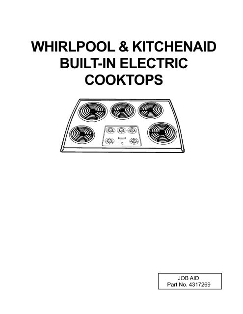
WHIRLPOOL & KITCHENAID<br />
BUILT-IN ELECTRIC<br />
COOKTOPS<br />
JOB AID<br />
Part No. 4317269
FORWARD<br />
This Job Aid, “<strong>Whirlpool</strong> & <strong>KitchenAid</strong> <strong>Built</strong>-<strong>In</strong> <strong>Electric</strong> <strong>Cooktops</strong>,” (Part No. 4317269), provides<br />
the technician with information on the installation and service of <strong>Whirlpool</strong> & <strong>KitchenAid</strong> <strong>Built</strong>-<strong>In</strong><br />
<strong>Electric</strong> <strong>Cooktops</strong>. It is to be used as a training Job Aid and Service Manual. For specific information<br />
on the model being serviced, refer to the “Use and Care Guide,” or “Tech Sheet” provided<br />
with the cooktop.<br />
The Wiring Diagrams used in this Job Aid are typical and should be used for training purposes<br />
only. Always use the Wiring Diagram supplied with the product when servicing the unit.<br />
GOALS AND OBJECTIVES<br />
The goal of this Job Aid is to provide detailed information that will enable the service technician to<br />
properly diagnose malfunctions and repair <strong>Built</strong>-<strong>In</strong> <strong>Electric</strong> <strong>Cooktops</strong>.<br />
The objectives of this Job Aid are to:<br />
• Understand and follow proper safety precautions.<br />
• Successfully troubleshoot and diagnose malfunctions.<br />
• Successfully perform necessary repairs.<br />
• Successfully return the cooktop to proper operational status.<br />
WHIRLPOOL CORPORATION assumes no responsibility for any repair<br />
made on our products by anyone other than Authorized Factory Service<br />
Technicians.<br />
Copyright 1999, <strong>Whirlpool</strong> Corporation, Benton Harbor, MI 49022<br />
- ii -
Table of Contents<br />
SPECIFICATIONS .................................................................................................................. 1-1<br />
INSTALLATION HIGHLIGHTS................................................................................................ 2-1<br />
<strong>Electric</strong>al Requirements ..................................................................................................... 2-1<br />
<strong>Electric</strong>al Connections ....................................................................................................... 2-2<br />
<strong>In</strong>stallation.......................................................................................................................... 2-4<br />
COMPONENT ACCESS ......................................................................................................... 3-1<br />
Component Locations ........................................................................................................ 3-1<br />
Removing The Maintop...................................................................................................... 3-2<br />
Removing The <strong>In</strong>dicator Light, An Element Control,<br />
A Coil Receptacle, & The T.O.D. .................................................................................... 3-4<br />
Removing The Ceramic Glass Maintop ............................................................................. 3-6<br />
COMPONENT TESTING ........................................................................................................ 4-1<br />
WIRING DIAGRAMS............................................................................................................... 5-1<br />
TECH TIPS ............................................................................................................................. 6-1<br />
- iii -<br />
PAGE
KITCHENAID MODEL & SERIAL NUMBER DESIGNATIONS<br />
MODEL NUMBER<br />
MODEL NUMBER<br />
INTERNATIONAL SALES IND.<br />
OR MARKETING CHANNEL<br />
IF PRESENT<br />
K=KITCHENAID BRAND<br />
PRODUCT IDENTIFICATION:<br />
EC=ELECTRIC COOKTOPS<br />
GC=GAS COOKTOPS<br />
MERCHANDISING SCHEME<br />
C=CERAMIC GLASS<br />
D=DOWNDRAFT VENT<br />
G=GRILL/GRIDDLE<br />
M=MODULAR DOWNDRAFT<br />
N=INTERNATIONAL COLLECTION<br />
P=PROFESSIONAL/COMMERCIAL<br />
S=STANDARD/PORCELAIN METAL<br />
T=TEMPERED GLASS<br />
X=208 VOLT<br />
E=ELECTRONICS<br />
CAPACITY/SIZE /SERIES/CONFIG<br />
1ST POSITION 2ND POSITION<br />
1=STANDARD 0=30" WIDE<br />
2=GRILL GRIDDLE 3=33" WIDE<br />
3=TEMPERED GLASS 6=36" WIDE<br />
4=COMMERCIAL 2=42" OR 12" WIDE<br />
5=CERAMIC GLASS 5=15" WIDE<br />
8=MODULAR/DOWNDRAFT<br />
0=2 BURNER/ELEMENT SYSTEM<br />
FEATURES<br />
0=STANDARD ELEMENTS/BURNERS<br />
1=RADIANT ELEMENTS<br />
2=DUAL ELEMENTS<br />
3=<br />
4=<br />
5=SEALED BURNERS/CAST ELEMENTS<br />
6=5 BURNERS/ELEMENTS<br />
7=HALOGEN ELEMENTS/6 BURNERS<br />
8=TOUCH CONTROLS<br />
9=INDUCTION<br />
YEAR OF INTRODUCTION<br />
G=1998 H=1999 J=2000<br />
COLOR CODE<br />
AL = Almond SS = Stainless<br />
BL = Black WH = White<br />
BT = Biscuit<br />
ENGINEERING CHANGE (NUMERIC)<br />
SERIAL NUMBER<br />
SERIAL NUMBER X H 07 1 2 3 4 5<br />
OXFORD<br />
YEAR OF INTRODUCTION:<br />
H = 1998, J = 1999, K = 2000<br />
WEEK OF PRODUCTION<br />
(7th WEEK)<br />
PRODUCT SEQUENCE NUMBER<br />
K E C S 16 1 G BL 0<br />
- iv -
WHIRLPOOL MODEL & SERIAL NUMBER DESIGNATIONS<br />
MODEL NUMBER<br />
R C S 30 0 4 G N ----<br />
MODEL NUMBER<br />
INTERNATIONAL SALES IND.<br />
OR MARKETING CHANNEL<br />
IF PRESENT<br />
PRODUCT GROUP:<br />
R = ELECTRIC COOKING PRODUCTS<br />
S = GAS COOKING PRODUCTS<br />
G = WHIRLPOOL GOLD RANGE<br />
PRODUCT IDENTIFICATION:<br />
C = BUILT-IN COOKTOP<br />
J = GOLD ELECTRIC COOKTOP<br />
G = GOLD GAS COOKTOP<br />
CONFIGURATION:<br />
S = PORCELAIN / STEEL TOP<br />
T = TEMPERED GLASS TOP<br />
C = CERAMIC GLASS TOP<br />
M = MODULAR DOWNDRAFT<br />
MODEL SIZE:<br />
20 = 20"<br />
30 = 30"<br />
36 = 36"<br />
FEATURE VARIATIONS:<br />
0 = LOW SPEED COIL ELECTRIC / OPEN-LOW END<br />
BURNER GAS / OPEN BAYS<br />
1 = HIGH SPEED COIL ELECTRIC / SEALED BURNERS<br />
2 = CERAMIC RADIANT ELECTRIC<br />
3 = CERAMIC RADIANT / DUAL<br />
4 = MODULAR<br />
- - - - - - - - - - - - - - - - - - - - - - - - - - - - - - - - - - - - - - - - - - - -<br />
0 = NO ELEMENTS / BURNERS<br />
2 = TWO ELEMENT / BURNER<br />
4 = FOUR ELEMENT / BURNER<br />
5 = FIVE ELEMENT / BURNER<br />
YEAR OF INTRODUCTION<br />
G = 1998 H = 1999 J = 2000<br />
COLOR CODE<br />
B = Black S = Stainless Steel<br />
N = Almond Z = Almond on Almond<br />
Q = White on White W = White<br />
ENGINEERING CHANGE (NUMERIC)<br />
SERIAL NUMBER<br />
SERIAL NUMBER X H 07 1 2 3 4 5<br />
OXFORD<br />
YEAR OF INTRODUCTION:<br />
H = 1998, J = 1999, K = 2000<br />
WEEK OF PRODUCTION<br />
(7th WEEK)<br />
PRODUCT SEQUENCE NUMBER<br />
- v -
MODEL & SERIAL NUMBER LABEL<br />
AND WIRING DIAGRAM LOCATIONS<br />
The Model/Serial Number label and Wiring Diagram locations are shown below.<br />
Wiring Diagram Location<br />
(on inside of switch box cover)<br />
Model & Serial Number<br />
Location* (on inside rear of<br />
burner box)<br />
* <strong>Whirlpool</strong> models & <strong>KitchenAid</strong> Ceramic glass models located on bottom of burner box.<br />
- vi -
IMPORTANT SAFETY INFORMATION<br />
Your safety and the safety of others is very important.<br />
Important safety messages have been provided in this Job Aid. Always read and obey all<br />
safety messages.<br />
This is the safety alert symbol.<br />
This symbol alerts you to hazards that can kill or hurt you and others.<br />
All safety messages will be preceded by the safety alert symbol and the word<br />
“WARNING.”<br />
All safety messages will identify the hazard, tell you how to reduce the chance of injury, and tell<br />
you what can happen if the instructions are not followed.<br />
- vii -
— NOTES —<br />
- viii -
SPECIFICATIONS<br />
KITCHENAID MODEL ELECTRIC<br />
PORCELAIN/METAL COIL COOKTOPS<br />
KECS100G & KECS161G<br />
WHIRLPOOL MODEL ELECTRIC<br />
PORCELAIN/METAL COIL COOKTOPS<br />
RCS2002G & RCS2012G RCS3004G, RCS3014G, &<br />
RCS3614G<br />
1-1
KITCHENAID MODEL ELECTRIC CERAMIC COOKTOPS<br />
KECC501G, KECC502G,<br />
YKECC502G, KECC507G, &<br />
YKECC507G<br />
WHIRLPOOL MODEL ELECTRIC CERAMIC COOKTOPS<br />
RCC3024G, GJC3034G, &<br />
GJC3634G<br />
1-2<br />
KECC562G, KECC567G &<br />
YKECC567G
20", 30", & 36" ELECTRIC PORCELAIN / METAL COIL COOKTOPS<br />
1-3
30" & 36" ELECTRIC CERAMIC COOKTOPS<br />
1-4
INSTALLATION HIGHLIGHTS<br />
If codes permit and a separate ground wire<br />
is used, it is recommended that a qualified<br />
electrician determine that the ground path<br />
is adequate.<br />
Do not ground to a gas pipe.<br />
Check with a qualified electrician if you are<br />
not sure whether the cooktop is properly<br />
grounded.<br />
Do not have a fuse in the neutral or ground<br />
circuit.<br />
240 VOLT COOKTOP<br />
1. A three-wire or four-wire, single phase,<br />
240-volt, 60-Hz, AC-only electrical supply<br />
is required on a separate, 40-ampere circuit,<br />
fused on both sides of the line. A timedelay<br />
fuse or circuit breaker is recommended.<br />
The fuse size must not exceed<br />
the circuit rating of the appliance specified<br />
on the model/serial rating plate located on<br />
the bottom of the cooktop.<br />
THE COOKTOP MUST BE CONNECTED<br />
WITH COPPER WIRE ONLY.<br />
ELECTRICAL REQUIREMENTS<br />
2-1<br />
2. Wire sizes and connections must conform<br />
to the requirements of the National <strong>Electric</strong>al<br />
Code ANSI/NFPA 70 — latest edition**,<br />
or CSA Standards C22.1-94, Canadian<br />
<strong>Electric</strong>al Code, Part 1 and C22.2 No.<br />
0-M91 — latest edition*** and all local<br />
codes and ordinances.<br />
3. The cooktop should be connected directly<br />
to the fused disconnect or circuit breaker<br />
box through flexible, armored or non-metallic<br />
sheathed, copper cable. The flexible,<br />
armored cable extending from the fuse<br />
box or circuit breaker box should be connected<br />
directly to the junction box.<br />
4. Locate the junction box to allow as much<br />
slack as possible between the junction<br />
box and the cooktop so that the cooktop<br />
can be moved if servicing is ever necessary.<br />
Do Not cut the conduit.<br />
5. A U.L. - or C.S.A.-listed conduit connector<br />
must be provided at each end of the power<br />
supply cable (at the cooktop and at the<br />
junction box).<br />
Copies of the standards listed above may be<br />
obtained from:<br />
**National Fire Protection Association<br />
Batterymarch Park<br />
Quincy, Massachusetts 02269<br />
***Canadian Standard Association<br />
178 Rexdale Boulevard<br />
Etobicoke, Ontario M9W 1R3
120 VOLT COOKTOP<br />
A 120-volt, 60-Hz, AC-only, 20-ampere, fused<br />
electrical supply is required. (Time-delay fuse<br />
or circuit breaker is recommended.) It is recommended<br />
that a separate circuit serving only<br />
this appliance be provided. A NEMA 5-20R, 3prong<br />
ground-type outlet must be used.<br />
WARNING<br />
<strong>Electric</strong>al Shock Hazard<br />
Plug into a grounded 3-prong outlet.<br />
Do not remove ground prong.<br />
Do not use an adapter.<br />
Do not use an extension cord.<br />
Failure to follow these instructions can<br />
result in death, fire, or electrical shock.<br />
WARNING<br />
<strong>Electric</strong>al Shock Hazard<br />
Turn power supply off before connecting<br />
wires.<br />
Use 8-gauge solid copper wire.<br />
<strong>Electric</strong>ally ground cooktop.<br />
Failure to follow these instructions can<br />
result in death, fire, or electrical shock.<br />
2-2<br />
Recommended ground method<br />
For your personal safety, this cooktop must be<br />
grounded. This cooktop is equipped with a<br />
power supply cord having a NEMA 5-20P, 3prong<br />
ground plug. To minimize possible shock<br />
hazard, the cord must be plugged into a mating,<br />
NEMA 5-20R, 3-prong ground-type outlet,<br />
grounded in accordance with the National <strong>Electric</strong>al<br />
Code, ANSI/NFPA 70—latest edition, and<br />
local codes and ordinances.<br />
120V, 20-amp, NEMA 5-20R, 3-<br />
3-prong ground-type outlet<br />
120V, 20-amp,<br />
NEMA 5-20P, 3-prong<br />
ground plug<br />
power supply cord<br />
ELECTRICAL CONNECTIONS<br />
ground<br />
prong<br />
If a mating outlet is not available, it is the personal<br />
responsibility and obligation of the customer<br />
to have a properly grounded, NEMA 5-<br />
20R, 3-prong outlet installed by a qualified electrician.<br />
This cooktop must be connected to a<br />
grounded, metallic permanent wiring system<br />
or a ground connector should be<br />
connected to the ground terminal or wire<br />
lead on the cooktop.<br />
This cooktop is manufactured with a frame<br />
connected, green or bare ground wire. Connect<br />
the cooktop cable to the junction box<br />
through the U.L. - or C.S.A.-listed conduit connector.<br />
Complete electrical connection according<br />
to local codes and ordinances.
Where local codes permit connecting the<br />
frame-ground conductor to the neutral<br />
(white) junction box wire (not used for Canadian<br />
installations):<br />
1. Disconnect the power supply.<br />
2. Connect the flexible, armored cable from<br />
the cooktop to the junction box using a<br />
U.L.- or C.S.A. -listed conduit connector<br />
and tighten the screws on the conduit<br />
connector.<br />
3. Connect the green (or bare) appliance<br />
cable wire with the neutral (white) wire in<br />
the junction box using a twist-on connector.<br />
4. Connect the two black wires together;<br />
then connect the two red wires together<br />
with a twist-on connector.<br />
red wires<br />
white wire<br />
bare or green<br />
wire<br />
cable from cooktop<br />
cable from<br />
power supply junction<br />
box<br />
Grounded Neutral<br />
twist-on<br />
connector<br />
black wires<br />
U.L. or CSA-listed<br />
conduit connector<br />
2-3<br />
Where local codes do not permit connecting<br />
the frame-ground conductor to the neutral<br />
(white) junction box wire (used for all<br />
Canadian installations):<br />
1. Disconnect the power supply.<br />
2. Connect the flexible, armored cable from<br />
the cooktop to the junction box using a<br />
U.L.- or C.S.A.-listed conduit connector,<br />
and tighten the screws on the conduit<br />
connector.<br />
3. Connect the two black wires together;<br />
then connect the two red wires together<br />
using a twist-on connector.<br />
4. Connect the green or bare ground wire<br />
from the appliance cable to the grounded<br />
wire in the junction box, or other grounded<br />
connector using a twist-on connector.<br />
5. <strong>In</strong>stall a twist-on connector on the end of<br />
the white wire.<br />
red wires<br />
bare or green<br />
wire<br />
cable from cooktop<br />
cable from<br />
power supply<br />
junction<br />
box<br />
Ungrounded Neutral<br />
white wire<br />
twist-on<br />
connector<br />
black wires<br />
U.L. or CSA-listed<br />
conduit connector
1. Remove the shipping materials and tape<br />
from the cooktop. Remove the hardware<br />
package from inside the literature bag.<br />
2. <strong>In</strong>sert the cooktop into the countertop and<br />
center it in the cutout. Position the front of<br />
the cooktop so that it is parallel to the front<br />
edge of the countertop. Make sure that all<br />
of the required clearances are met. NOTE:<br />
If cooktop is not properly positioned, lift the<br />
cooktop off the countertop to make the<br />
necessary adjustments.<br />
3. <strong>In</strong>sert one clamp tab through each slot located<br />
on sides of the burner box.<br />
screw<br />
clamp &<br />
screw<br />
assembly<br />
WARNING<br />
Excessive Weight Hazard<br />
Use two or more people to move and<br />
install the cooktop.<br />
Failure to do so can result in back or<br />
other injury.<br />
countertop cooktop<br />
clamp<br />
slot<br />
clamp tab<br />
burner box<br />
4. Secure the cooktop to the countertop by<br />
hand-tightening each screw, then use a<br />
screwdriver to tighten each screw by 1 to<br />
1-1/2 more turns. Do not overtighten.<br />
INSTALLATION<br />
2-4<br />
5. Models (KECS100 & KECS161) Only:<br />
Raise the cooktop as follows:<br />
a)Remove all elements and reflector<br />
bowls.<br />
b)Place your hands under left and right<br />
rear element cutouts and lift the maintop<br />
until the Posi-Lock bearings engage in<br />
their bracket holes to hold the maintop<br />
off the countertop. You will hear a “click”<br />
when the Posi-Lock engages.<br />
c) Lift the front of the maintop and position<br />
the support rod so that it rests<br />
against the front edge of the burner box.<br />
d)Check to make sure that there is enough<br />
slack in the electrical wiring conduit to<br />
properly lift and raise the maintop.<br />
NOTE: If you are installing the cooktop<br />
over a built-under oven, check to make<br />
sure that the maintop can be raised after<br />
oven installation is complete.<br />
switch box<br />
& cover<br />
support<br />
rod<br />
burner box<br />
maintop<br />
countertop<br />
conduit<br />
6. Make the electrical connections as instructed<br />
in the “<strong>Electric</strong>al Connections”<br />
beginning on page 2-2.<br />
7. Turn on the power supply to the cooktop.<br />
8. Depending on the model, push in and turn<br />
each control knob to the “Hl” position or<br />
touch “ON” and turn each control knob to<br />
the “Hl” position. Check the operation of<br />
the cooktop elements and indicator lights.
COMPONENT ACCESS<br />
This section instructs you on how to service<br />
each component inside the built-in electric coil<br />
cooktops. The components and their locations<br />
are shown in Figure 3-1.<br />
Maintop<br />
COMPONENT LOCATIONS<br />
Element Control<br />
(infinite switch)<br />
<strong>In</strong>dicator Light<br />
Figure 3-1<br />
3-1<br />
NOTE: The <strong>KitchenAid</strong> Model KECS161<br />
cooktop is shown below, however, the other<br />
built-in electric coil cooktop components are<br />
identical, and are serviced in the same manner.<br />
T.O.D. (on side<br />
of control box)<br />
Coil Element<br />
& Receptacles
REMOVING THE MAINTOP (Coil Models)<br />
WARNING<br />
<strong>Electric</strong>al Shock Hazard<br />
Disconnect from electrical supply before servicing<br />
unit.<br />
Failure to do so could result in death or<br />
electrical shock.<br />
CAUTION: When you work on the cooktop, be<br />
careful when handling the sheet metal parts.<br />
Sharp edges may be present, and you can cut<br />
yourself if you are not careful.<br />
1. Turn off the electrical power to the cooktop.<br />
2. Remove the knobs from the control stems.<br />
3. Unsnap the bezels and remove them. To<br />
remove a bezel, pull it toward you and lift<br />
the tabs out of the slots in the maintop (see<br />
Figure 3-2).<br />
Figure 3-2<br />
4. Remove the coil elements and the reflector<br />
bowls.<br />
5. Disconnect the conduit wires from the<br />
junction box wiring.<br />
6. Raise the maintop and position the support<br />
rod against the front of the burner box<br />
(see Figure 3-3).<br />
Figure 3-3<br />
3-2<br />
7. Remove the two screws from each of the<br />
two hinge covers at the rear of the burner<br />
box (see Figure 3-4).<br />
Hinge Cover<br />
Screws<br />
Figure 3-4<br />
Refer to Figure 3-5 for the following steps.<br />
8. Remove the green ground wire screw<br />
from the bottom of the burner box (the<br />
other end is attached to the right hinge).<br />
9. Lift the front of the maintop and unclip the<br />
support rod from the control box.<br />
10. Lift the maintop assembly off the burner<br />
box and pull the conduit out of the burner<br />
box opening, then position the maintop<br />
upside down (as shown in Figure 3-5) on<br />
a covered work surface.<br />
11. If you are replacing the maintop, remove<br />
the screws from the following components,<br />
and reinstall each one on the new maintop<br />
as you remove them:<br />
• Two hinges & ground wire<br />
• Four coil element receptacles<br />
• <strong>In</strong>dicator light (remove 2 wires from terminals)<br />
• Switch box assembly
Left Hinge<br />
Receptacle<br />
& Screw<br />
T.O.D.<br />
& 2 Screws<br />
Green Ground Wire<br />
H2<br />
L2 L1<br />
P<br />
H1<br />
H2<br />
L2 L1<br />
P<br />
H1<br />
Conduit<br />
H2<br />
L2 L1<br />
P<br />
H1<br />
3-3<br />
Right Hinge<br />
3 Screws 2 Screws<br />
Blue<br />
Wires<br />
Brown<br />
Wires<br />
Element Control<br />
(infinite switch)<br />
& 2 Screws<br />
Grey<br />
Wires<br />
Switch<br />
Box<br />
Figure 3-5<br />
Maintop<br />
H2<br />
L2 L1<br />
P<br />
H1<br />
H2<br />
L2 L1<br />
P<br />
H1<br />
<strong>In</strong>dicator Light<br />
Yellow<br />
Wires<br />
Orange<br />
Wires
REMOVING THE INDICATOR LIGHT, AN ELEMENT<br />
CONTROL, A COIL RECEPTACLE, & THE T.O.D.<br />
WARNING<br />
<strong>Electric</strong>al Shock Hazard<br />
Disconnect from electrical supply before servicing<br />
unit.<br />
Failure to do so could result in death or<br />
electrical shock.<br />
CAUTION: When you work on the cooktop, be<br />
careful when handling the sheet metal parts.<br />
Sharp edges may be present, and you can cut<br />
yourself if you are not careful.<br />
1. Turn off the electrical power to the cooktop.<br />
2. Raise the maintop and position the support<br />
rod against the front of the burner box<br />
(see Figure 3-6).<br />
Figure 3-6<br />
Refer to Figure 3-7 for the following steps.<br />
3. To remove the indicator light (inset #1):<br />
a)Disconnect the two wires from the terminals.<br />
b)Press in on the two locking arms and<br />
unclip them from the cooktop, then push<br />
the indicator light body up and out of<br />
the maintop opening.<br />
3-4<br />
4. To remove an element control (infinite<br />
switch)(inset #2):<br />
a)Remove the control knob from the control<br />
stem.<br />
b)Remove the two screws from the element<br />
control.<br />
c) Remove the two screws from the switch<br />
box cover and remove the cover.<br />
d)Disconnect the wires from the control<br />
terminals and remove the control and<br />
its rubber seal.<br />
5. To remove a coil receptacle (inset #3):<br />
a)Unplug the coil element from the receptacle.<br />
b)Remove the reflector bowl.<br />
c) Remove the screw from the receptacle<br />
bracket.<br />
d)Disconnect the two wires from the control<br />
terminals.<br />
6. To remove the T.O.D. (inset #4):<br />
a)Disconnect the two wires from the terminals.<br />
b)Remove the two screws and remove the<br />
T.O.D. from the switch box.
INSET #2<br />
Screws (2)<br />
Cooktop<br />
Rubber<br />
Seal<br />
Element Control<br />
(<strong>In</strong>finite Switch)<br />
Unclip<br />
From<br />
Cooktop<br />
Violet<br />
Wire<br />
INSET #1<br />
Red<br />
Wire<br />
Switch Box<br />
3-5<br />
Cooktop<br />
<strong>In</strong>dicator<br />
Light<br />
Switch Box Cover<br />
Screws (2)<br />
Hex-Head<br />
Screw<br />
Figure 3-7<br />
INSET #3<br />
Cooktop<br />
Switch Box<br />
T.O.D. With<br />
2 Screws<br />
Brown<br />
Wires<br />
Coil Receptacle<br />
INSET #4
REMOVING THE CERAMIC GLASS MAINTOP<br />
WARNING<br />
<strong>Electric</strong>al Shock Hazard<br />
Disconnect from electrical supply before servicing<br />
unit.<br />
Failure to do so could result in death or<br />
electrical shock.<br />
CAUTION: When you work on the cooktop, be<br />
careful when handling the sheet metal parts.<br />
Sharp edges may be present, and you can cut<br />
yourself if you are not careful.<br />
Ceramic<br />
Maintop<br />
Maintop Screw<br />
(1 of 14)<br />
Figure 3-8<br />
3-6<br />
1. Turn off the electrical power to the cooktop.<br />
Refer to Figure 3-8 for the following steps.<br />
2. Remove the control knobs from the control<br />
stems.<br />
3. Remove the fourteen (14) screws from the<br />
ceramic glass maintop frame and lift the<br />
maintop off the burner box.<br />
NOTE: If you are replacing the maintop, remove<br />
the four rubber grommets from the control<br />
stem holes.<br />
Control<br />
Knob
COMPONENT TESTING<br />
ELEMENT CONTROL<br />
(INFINITE SWITCH)<br />
L1<br />
L2<br />
H2<br />
P<br />
H1<br />
WARNING<br />
<strong>Electric</strong>al Shock Hazard<br />
Disconnect from electrical supply before servicing<br />
unit.<br />
Failure to do so could result in electrical<br />
shock or other personal injury.<br />
Test Procedure<br />
P<br />
L1<br />
L2<br />
H1 H2<br />
Refer to page 3-4 for the location of the element<br />
controls and the procedure for servicing<br />
them.<br />
To test a control, perform the following steps:<br />
1. Use an ohmmeter and set the range switch<br />
to R x 1.<br />
2. With no power applied, touch the leads of<br />
the ohmmeter to the indicated terminals of<br />
the element control (infinite switch). You<br />
should obtain the following readings:<br />
Control OFF:<br />
L1 to P = no continuity<br />
L1 to H1 = no continuity<br />
P to H1 = no continuity<br />
L2 to H2 = continuity<br />
Control to HI:<br />
L1 to P = continuity<br />
L1 to H1 = continuity<br />
P to H1 = continuity<br />
L2 to H2 = continuity<br />
4-1<br />
COIL ELEMENT<br />
WARNING<br />
<strong>Electric</strong>al Shock Hazard<br />
Disconnect from electrical supply before servicing<br />
unit.<br />
Failure to do so could result in electrical<br />
shock or other personal injury.<br />
Test Procedure<br />
Refer to page 3-4 for the location of the coil<br />
elements and the procedure for servicing them.<br />
To test an element, perform the following steps:<br />
1. Use an ohmmeter and set the range switch<br />
to R x 1.<br />
2. Remove the coil element you wish to test.<br />
3. Touch the ohmmeter leads to the terminals.<br />
You should obtain the following readings:<br />
6" element = 34 Ω and 52 Ω.<br />
8" element = 19 and 30 Ω.
INDICATOR LIGHT<br />
Terminals<br />
WARNING<br />
<strong>Electric</strong>al Shock Hazard<br />
Disconnect from electrical supply before servicing<br />
unit.<br />
Failure to do so could result in electrical<br />
shock or other personal injury.<br />
Test Procedure<br />
<strong>In</strong>dicator<br />
Light<br />
Refer to page 3-4 for the location of the indicator<br />
light and the procedure for servicing it.<br />
To test an indicator light, perform the following<br />
steps:<br />
1. Use a voltmeter and set it to read 120-volts<br />
AC.<br />
2. With power applied, measure across the<br />
light terminals. If the reading is 0-volts, check<br />
the wiring. If the meter reads 120-volts AC,<br />
replace the indicator light.<br />
4-2<br />
T.O.D.<br />
Terminals<br />
T.O.D.<br />
WARNING<br />
<strong>Electric</strong>al Shock Hazard<br />
Disconnect from electrical supply before servicing<br />
unit.<br />
Failure to do so could result in electrical<br />
shock or other personal injury.<br />
Test Procedure<br />
Refer to page 3-4 for the location of the T.O. D.<br />
and the procedure for servicing it.<br />
The T.O.D. operates as follows:<br />
Opens @ 150˚C (302˚F) ±5.5˚<br />
Closes @ 135˚C (275˚F) ±8.5˚
ELEMENTS<br />
Terminal<br />
Block<br />
Limiter<br />
Terminals<br />
<strong>Electric</strong>al Shock Hazard<br />
Disconnect from electrical supply before servicing<br />
unit.<br />
Failure to do so could result in electrical<br />
shock or other personal injury.<br />
Test Procedure<br />
WARNING<br />
To test an element, perform the following steps:<br />
1. Use an ohmmeter and set the range switch<br />
to R x 1.<br />
2. Disconnect the wires from the element<br />
you wish to test.<br />
3. Touch the ohmmeter leads to the element<br />
terminals. You should obtain the following<br />
readings:<br />
LF element:<br />
1000 W = 58 Ω.<br />
1400 W = 41 Ω.<br />
LR element (1200 W) = 47 Ω.<br />
RF element (1500 W) = 37 Ω.<br />
RR element (1800 W) = 31 Ω.<br />
Model GJC3634G shown.<br />
Element<br />
4-3<br />
LIMITERS<br />
2A 2B<br />
1A 1B<br />
WARNING<br />
2A 2B<br />
<strong>Electric</strong>al Shock Hazard<br />
Disconnect from electrical supply before servicing<br />
unit.<br />
Failure to do so could result in electrical<br />
shock or other personal injury.<br />
Test Procedure<br />
To test a limiter, perform the following steps:<br />
1. Use an ohmmeter and set the range switch<br />
to R x 1.<br />
2. Disconnect the wires from the limiter you<br />
wish to test.<br />
3. Touch the ohmmeter leads to the indicated<br />
limiter terminals. You should obtain<br />
the following readings:<br />
1A to 2A = Continuity (closed contacts)<br />
1B to 2B = <strong>In</strong>finity (open contacts)<br />
1A<br />
1B
— NOTES —<br />
4-4
WIRING DIAGRAMS<br />
WIRING DIAGRAMS<br />
<strong>Whirlpool</strong> Models RCS2002G & RCS2012G<br />
L1 NEUTRAL<br />
(BLK)<br />
(BLK)<br />
(BLK)<br />
(GRN) (GRN)<br />
Ground Conduit / Cord<br />
To Burner Box<br />
(ORG)<br />
Right Front<br />
Element<br />
(ORG)<br />
(BRN)<br />
Left Front<br />
Element<br />
(BRN)<br />
Ground Cooktop<br />
To Burner Box<br />
5-1<br />
<strong>In</strong>finite Switch RF Element<br />
H2 L2<br />
H1<br />
P<br />
L1<br />
<strong>In</strong>finite Switch LF Element<br />
H2 L2<br />
H1<br />
P<br />
L1<br />
(RED)<br />
(VLT)<br />
(RED)<br />
(VLT)<br />
<strong>In</strong>dicator Light<br />
(VLT)<br />
(WHITE)<br />
(RED)
<strong>Whirlpool</strong> Models RCS3004G, RCS3014G, & RCS3614G<br />
L1 L2<br />
(BLK)<br />
(GRN) (GRN)<br />
Ground Conduit To<br />
Switch Box<br />
(BRN)<br />
Right Front<br />
Element<br />
(BRN)<br />
(BLU)<br />
Right Rear<br />
Element<br />
(BLU)<br />
(ORG)<br />
Left Front<br />
Element<br />
(ORG)<br />
(YEL)<br />
Left Rear<br />
Element<br />
(YEL)<br />
Ground Hinge To<br />
Burner Box<br />
5-2<br />
<strong>In</strong>finite Switch RF Element<br />
H2 L2<br />
H1<br />
P<br />
L1<br />
<strong>In</strong>finite Switch RR Element<br />
H2 L2<br />
H1<br />
P<br />
L1<br />
<strong>In</strong>finite Switch LF Element<br />
H2 L2<br />
H1<br />
P<br />
L1<br />
<strong>In</strong>finite Switch LR Element<br />
H2 L2<br />
H1<br />
P<br />
L1<br />
(VLT)<br />
(VLT)<br />
(VLT)<br />
(VLT)<br />
<strong>In</strong>dicator Light<br />
(VLT)<br />
(RED)
<strong>Whirlpool</strong> Model RCC3024G<br />
5-3
<strong>Whirlpool</strong> Models GJC3034G, YGJC3034G, & GJC3634<br />
5-4
<strong>KitchenAid</strong> Model KECS100<br />
L1 L2<br />
(BLK)<br />
(GRN) (GRN)<br />
Ground Conduit To<br />
Switch Box<br />
(BRN)<br />
Right Front<br />
Element<br />
(BRN)<br />
(BLU)<br />
Right Rear<br />
Element<br />
(BLU)<br />
(ORG)<br />
Left Front<br />
Element<br />
(ORG)<br />
(YEL)<br />
Left Rear<br />
Element<br />
(YEL)<br />
T.O.D.<br />
Ground Hinge To<br />
Burner Box<br />
<strong>In</strong>finite Switch RF Element<br />
5-5<br />
H2 L2<br />
H1<br />
P<br />
L1<br />
<strong>In</strong>finite Switch RR Element<br />
H2 L2<br />
H1<br />
P<br />
L1<br />
<strong>In</strong>finite Switch LF Element<br />
H2 L2<br />
H1<br />
P<br />
L1<br />
<strong>In</strong>finite Switch LR Element<br />
H2 L2<br />
H1<br />
P<br />
L1<br />
(VLT)<br />
(VLT)<br />
(VLT)<br />
(VLT)<br />
<strong>In</strong>dicator Light<br />
(VLT)<br />
(RED)
L1 L2<br />
(BLK)<br />
<strong>KitchenAid</strong> Model KECS161<br />
(GRN) (GRN)<br />
Ground Conduit To<br />
Switch Box<br />
(BRN)<br />
Right Front<br />
Element<br />
(BRN)<br />
(BLU)<br />
Right Rear<br />
Element<br />
(BLU)<br />
(GRA)<br />
Center Rear<br />
Element<br />
(GRA)<br />
(ORG)<br />
Left Front<br />
Element<br />
(ORG)<br />
(YEL)<br />
Left Rear<br />
Element<br />
(YEL)<br />
T.O.D.<br />
T.O.D.<br />
Ground Hinge To<br />
Burner Box<br />
5-6<br />
<strong>In</strong>finite Switch RF Element<br />
H2 L2<br />
H1<br />
P<br />
L1<br />
<strong>In</strong>finite Switch RR Element<br />
H2 L2<br />
H1<br />
P<br />
L1<br />
<strong>In</strong>finite Switch CR Element<br />
H2 L2<br />
H1<br />
H2 L2<br />
H1<br />
P<br />
L1<br />
H2 L2<br />
H1<br />
P<br />
L1<br />
<strong>In</strong>finite Switch LF Element<br />
<strong>In</strong>finite Switch LR Element<br />
P<br />
L1<br />
(VLT)<br />
(VLT)<br />
(VLT)<br />
(VLT)<br />
(VLT)<br />
<strong>In</strong>dicator Light<br />
(VLT)<br />
(RED)
<strong>KitchenAid</strong> Models KECC501G & KECC502G<br />
5-7
<strong>KitchenAid</strong> Model KECC507<br />
5-8
<strong>KitchenAid</strong> Model KECC562<br />
5-9
<strong>KitchenAid</strong> Model KECC567<br />
5-10
TECH TIPS<br />
RAISING THE MAINTOP OFF THE COUNTER<br />
1. Remove all elements and reflector bowls.<br />
2. Place your hands under the left and right<br />
rear element opening areas and lift the<br />
maintop until the round ball tab seats in the<br />
hinge cover hole. You will hear a “click”<br />
when the ball is engaged. This will allow the<br />
maintop to be free of the countertop for<br />
cleaning or servicing.<br />
3. Rotate the support rod against the front of<br />
the burner box.<br />
6-1<br />
4. To lower the maintop:<br />
a) Lift cooktop slightly to disengage support<br />
rod, then lower the front to<br />
countertop level.<br />
b) Reach into left and right rear element<br />
opening areas and press the round ball<br />
tab to disengage it in its hole. The back<br />
of the maintop will lower itself back to<br />
countertop level.<br />
Press Round<br />
Ball Tab
REQUESTING ASSISTANCE OR SERVICE<br />
If you need assistance or service in the<br />
U.S. A.:<br />
Call the <strong>KitchenAid</strong> Consumer Assistance Center<br />
toll free, at<br />
1-800-422-1230, OR<br />
Call the <strong>Whirlpool</strong> Consumer Assistance<br />
Center,toll free at:<br />
1-800-253-1301.<br />
If you need assistance or service in Canada:<br />
Call the <strong>In</strong>glis Limited Consumer Assistance<br />
Center telephone number toll-free, 8:30 a.m.<br />
to 6:00 p.m. (EST) at:<br />
1-800-461-5681.<br />
Our consultants are available to assist you.<br />
When calling, please have the purchase date,<br />
and the complete model and serial number of<br />
your appliance handy. This information will help<br />
with your request.<br />
Our consultants provide assistance with:<br />
• Features and specifications on our full<br />
line of appliances.<br />
• <strong>In</strong>stallation information.<br />
• Use and maintenance procedures.<br />
• Accessory and repair parts sales.<br />
• Specialized customer assistance<br />
(Spanish & French (Canada) speaking,<br />
hearing impaired, limited vision, etc.).<br />
• Referrals to local dealers, service companies,<br />
and repair parts distributors.<br />
6-2<br />
<strong>KitchenAid</strong> and <strong>Whirlpool</strong> service technicians<br />
are trained to fulfill the product warranty and<br />
provide after-warranty service, anywhere in the<br />
United States. To locate the authorized<br />
<strong>KitchenAid</strong> or <strong>Whirlpool</strong> service company in<br />
your area, you can also look in your telephone<br />
directory Yellow Pages.<br />
If you need to order replacement parts, we<br />
recommend that you only use factory authorized<br />
parts. These parts will fit right and work<br />
right, because they are made with the same<br />
precision used to build every new <strong>KitchenAid</strong><br />
and <strong>Whirlpool</strong> appliance.<br />
To locate factory authorized replacement parts<br />
in your area, call our Consumer Assistance<br />
Center telephone number or your nearest authorized<br />
service center.<br />
If you need further assistance, you can write<br />
to <strong>KitchenAid</strong>, or <strong>Whirlpool</strong>, with any questions<br />
or concerns at:<br />
<strong>KitchenAid</strong>/<strong>Whirlpool</strong> Brand Home Appliances<br />
Consumer Assistance Center<br />
c/o Correspondence Dept.<br />
2000 North M-63<br />
Benton Harbor, Ml 49022-2692<br />
<strong>In</strong> Canada, contact:<br />
Consumer Relations Department<br />
<strong>In</strong>glis Limited<br />
1901 Minnesota Court<br />
Mississauga, Ontario L5N 3A7<br />
Please include a daytime phone number in<br />
your correspondence.
LENGTH OF<br />
WARRANTY:<br />
KITCHENAID ELECTRIC COOKTOP WARRANTY<br />
ONE-YEAR FULL<br />
WARRANTY<br />
FROM DATE OF<br />
PURCHASE.<br />
SECOND-<br />
THROUGH FIFTH-<br />
YEAR LIMITED<br />
WARRANTY<br />
FROM DATE OF<br />
PURCHASE.<br />
KITCHENAID<br />
WILL PAY FOR:<br />
Replacement parts<br />
and repair labor<br />
costs to correct<br />
defects in materials<br />
or workmanship.<br />
Service must<br />
be provided by an<br />
authorized<br />
<strong>KitchenAid</strong> servicing<br />
outlet.<br />
Replacement parts<br />
for any electric element<br />
to correct defects<br />
in materials or<br />
workmanship.<br />
KITCHENAID<br />
WILL NOT PAY FOR:<br />
A. Service calls to:<br />
1. Correct the installation of the cooktop.<br />
2. <strong>In</strong>struct you how to use the cooktop.<br />
3. Replace house fuses or correct house<br />
wiring.<br />
4. Correct house plumbing.<br />
B. Repairs when cooktop is used in other than<br />
normal home use.<br />
C. Damage resulting from accident, alteration,<br />
misuse, abuse, fire, flood, acts of God, improper<br />
installation, or installation not in accordance<br />
with local electrical or plumbing codes.<br />
D. Any labor costs during the limited warranties.<br />
E. Replacement parts or repair labor costs for<br />
units operated outside the United States and<br />
Canada.<br />
F. Pickup and delivery. This product is designed<br />
to be repaired in the home.<br />
G. Repairs to parts or systems resulting from unauthorized<br />
modifications made to the appliance.<br />
KITCHENAID DOES NOT ASSUME ANY RESPONSIBILITY FOR INCIDENTAL OR CONSE-<br />
QUENTIAL DAMAGES. Some states do not allow the exclusion or limitation of incidental or<br />
consequential damages, so this exclusion or limitation may not apply to you. This warranty gives<br />
specific legal rights and you may also have other rights which vary from state to state.<br />
Outside the United States, a different warranty may apply. For details, please contact your<br />
authorized <strong>KitchenAid</strong> dealer.<br />
If you need assistance or service, (U.S.A.), call our Consumer Assistance Center at 1-800-422-<br />
1230.<br />
6-3
LENGTH OF<br />
WARRANTY:<br />
KITCHENAID CERAMIC COOKTOP WARRANTY<br />
ONE-YEAR FULL<br />
WARRANTY<br />
FROM DATE OF<br />
PURCHASE.<br />
SECOND-<br />
THROUGH FIFTH-<br />
YEAR LIMITED<br />
WARRANTY<br />
FROM DATE OF<br />
PURCHASE.<br />
KITCHENAID<br />
WILL PAY FOR:<br />
Replacement parts<br />
and repair labor<br />
costs to correct<br />
defects in materials<br />
or workmanship.<br />
Service must<br />
be provided by an<br />
authorized<br />
<strong>KitchenAid</strong> servicing<br />
outlet.<br />
Replacement parts<br />
for any electric element<br />
to correct defects<br />
in materials or<br />
workmanship. Replacement<br />
Ceramic<br />
glass if breakage is<br />
due to defects in<br />
materials or workmanship.<br />
KITCHENAID<br />
WILL NOT PAY FOR:<br />
A. Service calls to:<br />
1. Correct the installation of the cooktop.<br />
2. <strong>In</strong>struct you how to use the cooktop.<br />
3. Replace house fuses or correct house<br />
wiring.<br />
B. Repairs when cooktop is used in other than<br />
normal home use.<br />
C. Damage resulting from accident, alteration,<br />
misuse, abuse, fire, flood, acts of God, improper<br />
installation, or installation not in accordance<br />
with local electrical or plumbing codes.<br />
D. Any labor costs during the limited warranties.<br />
E. Replacement parts or repair labor costs for<br />
units operated outside the United States and<br />
Canada.<br />
F. Pickup and delivery. This product is designed<br />
to be repaired in the home.<br />
G. Repairs to Ceramic glass cooktop if it has not<br />
been cared for as recommended in the Use &<br />
Care Guide.<br />
H. Repairs to parts or systems resulting from unauthorized<br />
modifications made to the appliance.<br />
I. <strong>In</strong> Canada, travel or transportation expenses<br />
for customers who reside in remote areas.<br />
KITCHENAID AND KITCHENAID CANADA DO NOT ASSUME ANY RESPONSIBILITY FOR<br />
INCIDENTAL OR CONSEQUENTIAL DAMAGES. Some states or provinces do not allow the<br />
exclusion or limitation of incidental or consequential damages, so this exclusion or limitation may<br />
not apply to you. This warranty gives specific legal rights and you may also have other rights<br />
which vary from state to state or province to province.<br />
Outside the United States and Canada, a different warranty may apply. For details, please<br />
contact your authorized <strong>KitchenAid</strong> dealer.<br />
If you need assistance or service, (U.S.A.), call our Consumer Assistance Center at 1-800-422-<br />
1230. <strong>In</strong> Canada, contact your authorized <strong>In</strong>glis Limited Appliance Service company.<br />
6-4
LENGTH OF<br />
WARRANTY:<br />
WHIRLPOOL ELECTRIC COOKTOP WARRANTY<br />
ONE-YEAR FULL<br />
WARRANTY<br />
FROM DATE OF<br />
PURCHASE.<br />
WHIRLPOOL<br />
WILL PAY FOR:<br />
FSP ® replacement<br />
parts and repair<br />
labor costs to<br />
correct defects in<br />
materials or workmanship.<br />
Service<br />
must be provided<br />
by an authorized<br />
<strong>Whirlpool</strong> service<br />
company.<br />
WHIRLPOOL<br />
WILL NOT PAY FOR:<br />
A. Service calls to:<br />
1. Correct the installation of the cooktop.<br />
2. <strong>In</strong>struct you how to use the cooktop.<br />
3. Replace house fuses or correct house<br />
wiring or plumbing.<br />
B. Repairs when the cooktop is used in other<br />
than normal, single-family household use.<br />
C. Pickup and delivery. The cooktop is designed<br />
to be repaired in the home.<br />
D. Damage to the cooktop caused by accident,<br />
alteration, misuse, abuse, fire, flood, acts of<br />
God, or use of products not approved by<br />
<strong>Whirlpool</strong>.<br />
E. Repairs to parts or systems resulting from unauthorized<br />
modifications made to the appliance.<br />
F. <strong>In</strong> Canada, travel or transportation expenses<br />
for customers who reside in remote areas.<br />
WHIRLPOOL CORPORATION SHALL NOT BE LIABLE FOR INCIDENTAL OR CONSEQUEN-<br />
TIAL DAMAGES. Some states or provinces do not allow the exclusion or limitation of incidental<br />
or consequential damages, so this exclusion or limitation may not apply to you. This warranty<br />
gives specific legal rights and you may also have other rights which vary from state to state or<br />
province to province.<br />
Outside the United States and Canada, a different warranty may apply. For details, please<br />
contact your authorized <strong>Whirlpool</strong> dealer.<br />
If you need service, call the <strong>Whirlpool</strong> Consumer Assistance Center telephone number, 1-800-<br />
253-1301, from anywhere in the U.S.A. <strong>In</strong> Canada, contact your authorized <strong>In</strong>glis Limited Appliance<br />
Service company.<br />
6-5
LENGTH OF<br />
WARRANTY:<br />
ONE-YEAR FULL<br />
WARRANTY<br />
FROM DATE OF<br />
PURCHASE.<br />
FULL 5-YEAR<br />
WARRANTY<br />
FROM DATE OF<br />
PURCHASE.<br />
WHIRLPOOL WILL NOT PAY FOR:<br />
WHIRLPOOL CLEANTOP ELECTRIC<br />
COOKTOP WARRANTY<br />
WHIRLPOOL WILL PAY FOR:<br />
FSP ® replacement parts and repair labor costs to correct defects in<br />
materials or workmanship. Service must be provided by an authorized<br />
<strong>Whirlpool</strong> service company.<br />
FSP ® replacement parts and repair labor for Cleantop Ceramic Glass<br />
Cooktop to the original purchaser of this product.<br />
Whirpool warrants that:<br />
– The Ceramic glass cooktop will not discolor.<br />
– The Ceramic glass cooktop pattern will not wear off.<br />
– The Ceramic glass cooktop will not crack due to thermal shock.<br />
– The surface units will not burn out.<br />
A. Service calls to:<br />
1. Correct the installation of the cooktop.<br />
2. <strong>In</strong>struct you how to use the cooktop.<br />
3. Replace house fuses or correct house wiring.<br />
B. Repairs when the cooktop is used in other than normal, single-family household use.<br />
C. Pickup and delivery. The cooktop is designed to be repaired in the home.<br />
D. Damage to the cooktop caused by accident, alteration, misuse, abuse, fire, flood, acts of<br />
God, or use of products not approved by <strong>Whirlpool</strong>.<br />
E. Repairs to Cleantop Ceramic Glass Cooktop if it has not been cared for as recommended<br />
in the Use & Care Guide.<br />
F. Repairs to parts or systems resulting from unauthorized modifications made to the appliance.<br />
G. <strong>In</strong> Canada, travel or transportation expenses for customers who reside in remote areas.<br />
WHIRLPOOL CORPORATION SHALL NOT BE LIABLE FOR INCIDENTAL OR CONSEQUEN-<br />
TIAL DAMAGES. Some states or provinces do not allow the exclusion or limitation of incidental<br />
or consequential damages, so this exclusion or limitation may not apply to you. This warranty<br />
gives specific legal rights and you may also have other rights which vary from state to state or<br />
province to province.<br />
Outside the United States and Canada, a different warranty may apply. For details, please<br />
contact your authorized <strong>Whirlpool</strong> dealer.<br />
If you need service, call the <strong>Whirlpool</strong> Consumer Assistance Center telephone number, 1-800-<br />
253-1301, from anywhere in the U.S.A. <strong>In</strong> Canada, contact your authorized <strong>In</strong>glis Limited Appliance<br />
Service company.<br />
6-6