UPGRADING REPAIRING PCs
UPGRADING REPAIRING PCs
UPGRADING REPAIRING PCs

You also want an ePaper? Increase the reach of your titles
YUMPU automatically turns print PDFs into web optimized ePapers that Google loves.
76<br />
Chapter 3—BIOS Configurations and Upgrades<br />
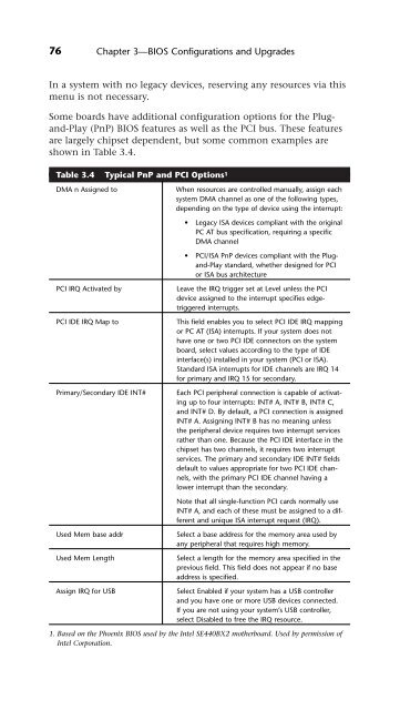
In a system with no legacy devices, reserving any resources via this<br />
menu is not necessary.<br />
Some boards have additional configuration options for the Plugand-Play<br />
(PnP) BIOS features as well as the PCI bus. These features<br />
are largely chipset dependent, but some common examples are<br />
shown in Table 3.4.<br />
Table 3.4 Typical PnP and PCI Options 1<br />
DMA n Assigned to When resources are controlled manually, assign each<br />
system DMA channel as one of the following types,<br />
depending on the type of device using the interrupt:<br />
• Legacy ISA devices compliant with the original<br />
PC AT bus specification, requiring a specific<br />
DMA channel<br />
• PCI/ISA PnP devices compliant with the Plugand-Play<br />
standard, whether designed for PCI<br />
or ISA bus architecture<br />
PCI IRQ Activated by Leave the IRQ trigger set at Level unless the PCI<br />
device assigned to the interrupt specifies edgetriggered<br />
interrupts.<br />
PCI IDE IRQ Map to This field enables you to select PCI IDE IRQ mapping<br />
or PC AT (ISA) interrupts. If your system does not<br />
have one or two PCI IDE connectors on the system<br />
board, select values according to the type of IDE<br />
interface(s) installed in your system (PCI or ISA).<br />
Standard ISA interrupts for IDE channels are IRQ 14<br />
for primary and IRQ 15 for secondary.<br />
Primary/Secondary IDE INT# Each PCI peripheral connection is capable of activating<br />
up to four interrupts: INT# A, INT# B, INT# C,<br />
and INT# D. By default, a PCI connection is assigned<br />
INT# A. Assigning INT# B has no meaning unless<br />
the peripheral device requires two interrupt services<br />
rather than one. Because the PCI IDE interface in the<br />
chipset has two channels, it requires two interrupt<br />
services. The primary and secondary IDE INT# fields<br />
default to values appropriate for two PCI IDE channels,<br />
with the primary PCI IDE channel having a<br />
lower interrupt than the secondary.<br />
Note that all single-function PCI cards normally use<br />
INT# A, and each of these must be assigned to a different<br />
and unique ISA interrupt request (IRQ).<br />
Used Mem base addr Select a base address for the memory area used by<br />
any peripheral that requires high memory.<br />
Used Mem Length Select a length for the memory area specified in the<br />
previous field. This field does not appear if no base<br />
address is specified.<br />
Assign IRQ for USB Select Enabled if your system has a USB controller<br />
and you have one or more USB devices connected.<br />
If you are not using your system’s USB controller,<br />
select Disabled to free the IRQ resource.<br />
1. Based on the Phoenix BIOS used by the Intel SE440BX2 motherboard. Used by permission of<br />
Intel Corporation.