UPGRADING REPAIRING PCs
UPGRADING REPAIRING PCs UPGRADING REPAIRING PCs
42 Chapter 2—System Components and Configuration Startup and observe POST. If errors are encountered, go to defect isolation procedures. Defect Isolation Procedures. If count does not match, go to defect isolation procedures. If problems are encountered, go to Defect Isolation Procedures. If POST completes with no errors, basic functionality has been tested. Restart system, enter Bios (or CMOS) setup. Verify that memory count is equal to installed amount. While in the BIOS, set all cache options to disabled, save settings and boot to a DOS formatted (floppy) system disk. Use a diagnostics program to test system base and extended memory. If no problems are encountered, memory has tested OK. Reboot, enter BIOS setup re-enable. Figure 2.11 184-pin DDR (Double Data Rate) SDRAM DIMM. DDR DIMMs are rated for either PC200 (100MHz x 2) or PC266 (133MHz x 2) operation and normally run on 2.5 volts. They are basically an extension of the PC100 and PC133 DIMMs redesigned to support double clocking, where data is sent on each clock transition (twice per cycle) rather than once per cycle as is standard with SDRAM. Parity Versus Non-Parity Memory Parity-checked RAM uses units of 8 memory bits plus 1 parity bit, for a total of 9 bits. In addition, parity checking uses both the data bits and the parity bit to ensure that memory contents are accurate with each memory access. Virtually all 386-based and older systems, and most 486-based systems, require parity-checked memory, which can detect, but not correct, memory errors. On the other hand, most Pentium-class
and higher systems don’t require parity-checked RAM, but will ignore the parity bit(s) if present. Parity-checked memory must be used on systems that require it, and should be used on systems that can be configured to use the parity bits, especially if the systems support ECC (Error Correction Code) operation, which uses the parity bit as a means of correcting a faulty memory bit. Requirements for ECC Memory Use ECC requires the following: • Parity-checked memory modules • A motherboard chipset that offers ECC support • ECC support enabled in the BIOS system configuration ECC operation is recommended for servers and other systems that are performing mission-critical tasks because ECC operation can correct single-bit memory errors. Larger memory errors will cause the system to display an error message and halt. However, systems using ECC will cost more due to the higher cost of parity-checked RAM. Additionally, system performance is slightly slower due to the extra time involved in ECC operation. Check your motherboard or system documentation to determine whether ECC is an option for your system. To determine whether a memory module supports parity-checking or ECC, use the following tips. Using the Divide by 3 Rule to Determine Parity Support Count the chips on a SIMM or DIMM. If you can divide the number of chips by 3, the module is most likely a parity-checked module. However, some memory manufacturers have created memory modules with fake parity chips; these are referred to as logic parity modules. Note Memory Types 43 See Upgrading and Repairing PCs, 12th Edition, Chapter 6, for more information about how to detect a logic parity module. Using the Divide by 9 Rule to Determine Parity Support A similar “divide by 9” rule can also be used to determine parity checking if you know the number of memory bits in the module. Note in Table 2.16 that the number of bits in parity-checked
- Page 9 and 10: Serial Port Configuration 172 Avoid
- Page 11 and 12: Contents xi Sound Quality Standards
- Page 13 and 14: About the Authors Scott Mueller is
- Page 15 and 16: watch, photograph, and (occasionall
- Page 17 and 18: Tell Us What You Think! As the read
- Page 19 and 20: Chapter 1 General Technical Referen
- Page 21 and 22: Understanding Bits, Nibbles, and By
- Page 23 and 24: Note Glossary of Essential Terms 5
- Page 25 and 26: Glossary of Essential Terms 7 Table
- Page 27 and 28: Glossary of Essential Terms 9 Table
- Page 29 and 30: Table 1.5 Hexadecimal/ASCII Convers
- Page 31 and 32: Hexadecimal/ASCII Conversions 13 Ta
- Page 33 and 34: Table 1.5 Hexadecimal/ASCII Convers
- Page 35: Hexadecimal/ASCII Conversions 17 Ta
- Page 38 and 39: 20 Chapter 2—System Components an
- Page 40 and 41: 22 Chapter 2—System Components an
- Page 42 and 43: 24 Chapter 2—System Components an
- Page 44 and 45: 26 Chapter 2—System Components an
- Page 46 and 47: 28 Chapter 2—System Components an
- Page 48 and 49: 30 Chapter 2—System Components an
- Page 50 and 51: 32 Chapter 2—System Components an
- Page 52 and 53: 34 Chapter 2—System Components an
- Page 54 and 55: 36 Caution Chapter 2—System Compo
- Page 56 and 57: 38 Table 2.15 Troubleshooting Power
- Page 58 and 59: 40 Chapter 2—System Components an
- Page 62 and 63: 44 modules can be divided by 9, but
- Page 64 and 65: 46 Chapter 2—System Components an
- Page 66 and 67: 48 Chapter 2—System Components an
- Page 68 and 69: 50 Other Add-On Card Configuration
- Page 70 and 71: 52 Chapter 2—System Components an
- Page 72 and 73: 54 Chapter 2—System Components an
- Page 74 and 75: 56 Chapter 2—System Components an
- Page 76 and 77: 58 Chapter 2—System Components an
- Page 78 and 79: 60 Chapter 2—System Components an
- Page 80 and 81: 62 Chapter 2—System Components an
- Page 82 and 83: 64 Chapter 2—System Components an
- Page 84 and 85: 66 Chapter 2—System Components an
- Page 87 and 88: Chapter 3 3 BIOS Configurations and
- Page 89 and 90: Where BIOS Updates Come From 71 Tab
- Page 91 and 92: How to Recover from a Failed BIOS U
- Page 93 and 94: Note A complete list of PnP device
- Page 95 and 96: Other BIOS Troubleshooting Tips 77
- Page 97 and 98: Determining the Motherboard Manufac
- Page 99 and 100: Determining the Motherboard Manufac
- Page 101 and 102: Table 3.8 Common Keystrokes Used to
- Page 103 and 104: Phoenix BIOS Beep Codes The followi
- Page 105 and 106: Port 80h Beep Code Codes Error Mess
- Page 107 and 108: BIOS Configuration Worksheet 89 BIO
- Page 109 and 110: BIOS Configuration Worksheet 91 Sha
42<br />
Chapter 2—System Components and Configuration<br />
Startup and<br />
observe POST.<br />
If errors are<br />
encountered,<br />
go to defect<br />
isolation<br />
procedures.<br />
Defect<br />
Isolation<br />
Procedures.<br />
If count does<br />
not match, go to<br />
defect isolation<br />
procedures.<br />
If problems are<br />
encountered, go<br />
to Defect Isolation<br />
Procedures.<br />
If POST completes<br />
with no errors,<br />
basic functionality<br />
has been tested.<br />
Restart system,<br />
enter Bios (or CMOS)<br />
setup. Verify that<br />
memory count is<br />
equal to installed<br />
amount.<br />
While in the BIOS,<br />
set all cache options<br />
to disabled, save<br />
settings and boot to<br />
a DOS formatted<br />
(floppy) system disk.<br />
Use a diagnostics<br />
program to test<br />
system base and<br />
extended memory.<br />
If no problems are<br />
encountered, memory<br />
has tested OK.<br />
Reboot, enter BIOS<br />
setup re-enable.<br />
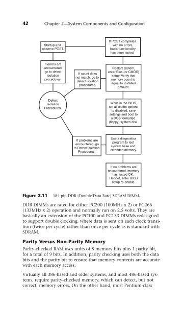
Figure 2.11 184-pin DDR (Double Data Rate) SDRAM DIMM.<br />
DDR DIMMs are rated for either PC200 (100MHz x 2) or PC266<br />
(133MHz x 2) operation and normally run on 2.5 volts. They are<br />
basically an extension of the PC100 and PC133 DIMMs redesigned<br />
to support double clocking, where data is sent on each clock transition<br />
(twice per cycle) rather than once per cycle as is standard with<br />
SDRAM.<br />
Parity Versus Non-Parity Memory<br />
Parity-checked RAM uses units of 8 memory bits plus 1 parity bit,<br />
for a total of 9 bits. In addition, parity checking uses both the data<br />
bits and the parity bit to ensure that memory contents are accurate<br />
with each memory access.<br />
Virtually all 386-based and older systems, and most 486-based systems,<br />
require parity-checked memory, which can detect, but not<br />
correct, memory errors. On the other hand, most Pentium-class


