- Page 1 and 2:
UPGRADING AND REPAIRING PCs TECHNIC
- Page 3 and 4:
Associate Publisher Greg Wiegand Se
- Page 5 and 6:
Contents 1 General Technical Refere
- Page 7 and 8:
Contents vii IDE Hard Drive Identif
- Page 9 and 10:
Serial Port Configuration 172 Avoid
- Page 11 and 12:
Contents xi Sound Quality Standards
- Page 13 and 14:
About the Authors Scott Mueller is
- Page 15 and 16:
watch, photograph, and (occasionall
- Page 17 and 18:
Tell Us What You Think! As the read
- Page 19 and 20:
Chapter 1 General Technical Referen
- Page 21 and 22:
Understanding Bits, Nibbles, and By
- Page 23 and 24:
Note Glossary of Essential Terms 5
- Page 25 and 26:
Glossary of Essential Terms 7 Table
- Page 27 and 28:
Glossary of Essential Terms 9 Table
- Page 29 and 30:
Table 1.5 Hexadecimal/ASCII Convers
- Page 31 and 32:
Hexadecimal/ASCII Conversions 13 Ta
- Page 33 and 34:
Table 1.5 Hexadecimal/ASCII Convers
- Page 35:
Hexadecimal/ASCII Conversions 17 Ta
- Page 38 and 39:
20 Chapter 2—System Components an
- Page 40 and 41:
22 Chapter 2—System Components an
- Page 42 and 43:
24 Chapter 2—System Components an
- Page 44 and 45:
26 Chapter 2—System Components an
- Page 46 and 47:
28 Chapter 2—System Components an
- Page 48 and 49:
30 Chapter 2—System Components an
- Page 50 and 51:
32 Chapter 2—System Components an
- Page 52 and 53:
34 Chapter 2—System Components an
- Page 54 and 55:
36 Caution Chapter 2—System Compo
- Page 56 and 57:
38 Table 2.15 Troubleshooting Power
- Page 58 and 59:
40 Chapter 2—System Components an
- Page 60 and 61:
42 Chapter 2—System Components an
- Page 62 and 63: 44 modules can be divided by 9, but
- Page 64 and 65: 46 Chapter 2—System Components an
- Page 66 and 67: 48 Chapter 2—System Components an
- Page 68 and 69: 50 Other Add-On Card Configuration
- Page 70 and 71: 52 Chapter 2—System Components an
- Page 72 and 73: 54 Chapter 2—System Components an
- Page 74 and 75: 56 Chapter 2—System Components an
- Page 76 and 77: 58 Chapter 2—System Components an
- Page 78 and 79: 60 Chapter 2—System Components an
- Page 80 and 81: 62 Chapter 2—System Components an
- Page 82 and 83: 64 Chapter 2—System Components an
- Page 84 and 85: 66 Chapter 2—System Components an
- Page 87 and 88: Chapter 3 3 BIOS Configurations and
- Page 89 and 90: Where BIOS Updates Come From 71 Tab
- Page 91 and 92: How to Recover from a Failed BIOS U
- Page 93 and 94: Note A complete list of PnP device
- Page 95 and 96: Other BIOS Troubleshooting Tips 77
- Page 97 and 98: Determining the Motherboard Manufac
- Page 99 and 100: Determining the Motherboard Manufac
- Page 101 and 102: Table 3.8 Common Keystrokes Used to
- Page 103 and 104: Phoenix BIOS Beep Codes The followi
- Page 105 and 106: Port 80h Beep Code Codes Error Mess
- Page 107 and 108: BIOS Configuration Worksheet 89 BIO
- Page 109 and 110: BIOS Configuration Worksheet 91 Sha
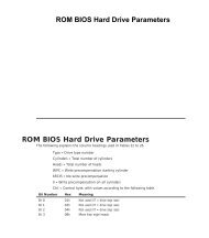
- Page 111: 4 SCSI and IDE Hard Drives and Opti
- Page 115 and 116: Breaking the 504MB (528-Million-Byt
- Page 117 and 118: Table 4.3 Using LBA Mode Operating
- Page 119 and 120: 5. Use the #4 option—View Current
- Page 121 and 122: Using LBA Mode 103 Table 4.6 Why ID
- Page 123 and 124: Sources for BIOS Upgrades 105 Table
- Page 125 and 126: Improving Hard Disk Speed 107 Figur
- Page 127 and 128: Bus-Mastering Chipsets for IDE 109
- Page 129 and 130: Table 4.13 Bus-Mastering Chipsets b
- Page 131 and 132: Table 4.14 Other IDE Drive Installa
- Page 133 and 134: standard single-ended SCSI devices
- Page 135 and 136: SCSI Drive and Device Configuration
- Page 137 and 138: SCSI Drive and Device Configuration
- Page 139 and 140: Following these tips will help mini
- Page 141 and 142: SCSI Configuration Troubleshooting
- Page 143 and 144: Using FDISK 125 Using FDISK FDISK i
- Page 145 and 146: Benefits of Hard Disk Partitioning
- Page 147 and 148: How FDISK and the Operating System
- Page 149 and 150: How FDISK and the Operating System
- Page 151 and 152: Now, the operating system can use t
- Page 153 and 154: The command switches are explained
- Page 155 and 156: MS-DOS Command-Line Access to CD-RO
- Page 157 and 158: • Make sure the drive shows up as
- Page 159: Troubleshooting Optical Drives 141
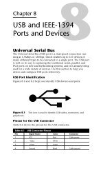
- Page 162 and 163:
144 Chapter 5—Floppy, Removable,
- Page 164 and 165:
146 Chapter 5—Floppy, Removable,
- Page 166 and 167:
148 Chapter 5—Floppy, Removable,
- Page 168 and 169:
150 Chapter 5—Floppy, Removable,
- Page 170 and 171:
152 Chapter 5—Floppy, Removable,
- Page 172 and 173:
154 Chapter 5—Floppy, Removable,
- Page 174 and 175:
156 • OnStream’s ADR (Advanced
- Page 176 and 177:
158 Chapter 5—Floppy, Removable,
- Page 178 and 179:
160 Table 5.13 High-Performance Tap
- Page 180 and 181:
162 Chapter 5—Floppy, Removable,
- Page 182 and 183:
164 Chapter 5—Floppy, Removable,
- Page 184 and 185:
166 Chapter 6—Serial Ports and Mo
- Page 186 and 187:
168 Table 6.2 25-Pin (PC, XT, and P
- Page 188 and 189:
170 Table 6.4 Overview of UART Chip
- Page 190 and 191:
172 Chapter 6—Serial Ports and Mo
- Page 192 and 193:
174 Chapter 6—Serial Ports and Mo
- Page 194 and 195:
176 Chapter 6—Serial Ports and Mo
- Page 196 and 197:
178 Chapter 6—Serial Ports and Mo
- Page 198 and 199:
180 Chapter 6—Serial Ports and Mo
- Page 200 and 201:
182 Chapter 6—Serial Ports and Mo
- Page 202 and 203:
184 Chapter 6—Serial Ports and Mo
- Page 204 and 205:
186 Chapter 6—Serial Ports and Mo
- Page 206 and 207:
188 (These settings require changes
- Page 208 and 209:
190 Chapter 7—Parallel Ports, Pri
- Page 210 and 211:
192 Building a Parallel Loopback Pl
- Page 212 and 213:
194 Chapter 7—Parallel Ports, Pri
- Page 214 and 215:
196 Chapter 7—Parallel Ports, Pri
- Page 216 and 217:
198 Chapter 7—Parallel Ports, Pri
- Page 218 and 219:
200 Chapter 7—Parallel Ports, Pri
- Page 220 and 221:
202 Chapter 7—Parallel Ports, Pri
- Page 222:
204 Chapter 7—Parallel Ports, Pri