upgrading and repairing PCs technicians ... - 400 Bad Request
upgrading and repairing PCs technicians ... - 400 Bad Request
upgrading and repairing PCs technicians ... - 400 Bad Request

You also want an ePaper? Increase the reach of your titles
YUMPU automatically turns print PDFs into web optimized ePapers that Google loves.
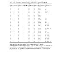
Chapter 8<br />
USB <strong>and</strong> IEEE-1394<br />
Ports <strong>and</strong> Devices<br />
8<br />
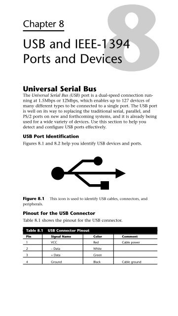
Universal Serial Bus<br />
The Universal Serial Bus (USB) port is a dual-speed connection running<br />
at 1.5Mbps or 12Mbps, which enables up to 127 devices of<br />
many different types to be connected to a single port. The USB port<br />
is well on its way to replacing the traditional serial, parallel, <strong>and</strong><br />
PS/2 ports on new <strong>and</strong> forthcoming systems, <strong>and</strong> it is already being<br />
used for a wide variety of devices. Use this section to help you<br />
detect <strong>and</strong> configure USB ports effectively.<br />
USB Port Identification<br />
Figures 8.1 <strong>and</strong> 8.2 help you identify USB devices <strong>and</strong> ports.<br />
Figure 8.1 This icon is used to identify USB cables, connectors, <strong>and</strong><br />
peripherals.<br />
Pinout for the USB Connector<br />
Table 8.1 shows the pinout for the USB connector.<br />
Table 8.1 USB Connector Pinout<br />
Pin Signal Name Color Comment<br />
1 VCC Red Cable power<br />
2 – Data White<br />
3 + Data Green<br />
4 Ground Black Cable ground
206<br />
Chapter 8—USB <strong>and</strong> IEEE-1394 Ports <strong>and</strong> Devices<br />
SERIES “A”<br />
USB Connector<br />
SERIES “B”<br />
USB Connector<br />
Figure 8.2 USB Series A <strong>and</strong> Series B plugs <strong>and</strong> receptacles.<br />
Typical USB Port Locations<br />
SERIES “A”<br />
USB Socket<br />
SERIES “B”<br />
USB Socket<br />
The location of USB ports varies with the system. On late-model<br />
desktop <strong>and</strong> tower computers using baby-AT motherboards, you<br />
might find one or two USB ports on a card bracket in the rear of<br />
the computer. The ports might be mounted on an add-on card or<br />
cabled out from motherboard ports.<br />
Most systems using ATX, NTX, or similar motherboards—as well as<br />
late-model LPX-based systems—will have one or two USB ports on<br />
the rear of the case next to other ports.<br />
Some consumer-oriented, late-model systems have one USB port on<br />
the front, sometimes located next to a 9-pin serial port. These ports<br />
are located in the front of the computer for easier connection of<br />
digital cameras <strong>and</strong> card readers for digital image downloading.<br />
Adding USB Ports to Your Computer<br />
If your computer doesn’t have USB ports onboard, use one of the<br />
following options to add them:<br />
• Purchase USB header cables to extend motherboard USB<br />
cable connectors to the outside of the case.<br />
• Purchase <strong>and</strong> install a USB host adapter card.
Even if your baby-AT system has connectors for USB header cables,<br />
changes in the USB spec make installing an up-to-date USB host<br />
adapter card a better idea for many users.<br />
Prerequisites for Using USB Ports <strong>and</strong> Peripherals<br />
Before you buy or try to install a USB peripheral, make sure your<br />
system meets the requirements shown in Table 8.2. Some adjustments<br />
or updates to the system configuration might be necessary.<br />
Table 8.2 Prerequisites for Use of USB Ports/Peripherals<br />
Requirement Reason Notes<br />
Windows 98 Built-in support for USB Windows 95B OSR 2.1 <strong>and</strong> above<br />
Windows 2000 peripherals have USB support, but many peri-<br />
Windows Millennium<br />
Edition<br />
pherals require Win98 or above.<br />
Working USB ports Many systems shipped Check BIOS <strong>and</strong> enable there if<br />
with disabled USB ports necessary; some systems might<br />
require header cables to bring the<br />
USB connector to the rear of the<br />
system.<br />
You can download the free USB Ready utility program at<br />
www.usb.org/data/usbready.exe to check your system’s USB<br />
readiness at both hardware <strong>and</strong> software levels.<br />
Verify that the peripheral you are installing is designed for your<br />
operating system. Although USB ports themselves are found on<br />
both PC <strong>and</strong> Macintosh systems, some USB devices are for use only<br />
on <strong>PCs</strong> or Macintoshes, not both types of systems.<br />
Troubleshooting USB Ports<br />
USB ports built into the computer (also called root hubs) are becoming<br />
the primary external device connection for an increasing number<br />
of <strong>PCs</strong>. While USB devices are plug <strong>and</strong> play, requiring (<strong>and</strong><br />
allowing!) no configuration, persistent problems with USB devices<br />
are common for many users. Use the following tips to help you<br />
achieve reliable USB operation:<br />
• Check Prerequisites from Table 8.2.<br />
Universal Serial Bus 207<br />
• If devices don’t work when plugged into an external hub,<br />
plug them into the root hub (USB connector on the system);<br />
if they work when attached to the root hub, upgrade the<br />
external hub’s firmware, attach a power supply to it, or<br />
replace it.<br />
• If a new device isn’t detected, remove other USB devices,<br />
plug in the new device first, <strong>and</strong> then reattach the other USB<br />
devices.
208<br />
Chapter 8—USB <strong>and</strong> IEEE-1394 Ports <strong>and</strong> Devices<br />
• Check the power usage for the USB bus in the Power dialog<br />
box of the operating system.<br />
• Verify that the USB device is drawing no less than 50mA <strong>and</strong><br />
no more than 500mA.<br />
• Use the Windows Device Manager to verify proper operation<br />
of the USB port; adjust IRQ settings if necessary to avoid<br />
conflicts with other devices.<br />
• Install the latest USB device drivers for the device <strong>and</strong> the<br />
operating system; USB devices that work in Windows 98<br />
might not be supported by other versions of Windows.<br />
• If a printer doesn’t work properly with the “correct” USB<br />
driver, try using a compatible driver for an older model as a<br />
workaround.<br />
• Install the latest firmware for the USB device; bad firmware<br />
creates “ghost” versions of devices in the Device Manager<br />
when the device is unplugged <strong>and</strong> reattached.<br />
• Verify that the USB root hub (port) is assigned an IRQ; normally<br />
IRQ 9 is used if available. Make sure IRQ steering is<br />
working if all available IRQs are already assigned to other<br />
ports.<br />
• Use high-speed (heavily shielded) cabling for high-speed<br />
devices, such as printers, scanners, <strong>and</strong> network connections.<br />
• Separate low-speed from high-speed devices by attaching<br />
them to separate USB ports.<br />
• Assign USB controllers to Controller ID 1 if not detected by<br />
the game.<br />
• Use the smallest number of hubs possible; some versions of<br />
Windows can’t use over 5 USB hubs (some devices double as<br />
hubs).<br />
• Before you purchase a USB device, verify device driver support<br />
for your operating system; Windows 2000 supports USB<br />
devices, but many vendors are slow about supplying USB<br />
drivers for Windows 2000.<br />
• When possible, buy devices that can be connected by either<br />
a USB port or a so-called “legacy” port (PS/2 keyboard/mouse<br />
port, serial port, parallel port, or SCSI port) to enable you to<br />
use the device even if you have problems with your USB<br />
ports or peripherals.
Using USB Hubs with Legacy (Serial, Parallel, <strong>and</strong><br />
PS/2) Ports<br />
A number of products on the market enable you to connect various<br />
legacy products to USB ports. The most economical way to connect<br />
serial, parallel, or PS/2-port products is through the use of a multipurpose<br />
hub that also features multiple USB ports.<br />
You can also purchase serial-to-USB or parallel-to-USB converter<br />
cables, but these are less flexible <strong>and</strong> more expensive if you need to<br />
connect multiple legacy devices to a system.<br />
Check the list of supported legacy devices before you buy a converter<br />
cable or multi-purpose port. USB hubs with PS/2 <strong>and</strong> serial<br />
ports normally support legacy devices such as modems, keyboards,<br />
<strong>and</strong> mice; USB hubs with parallel ports normally support printers.<br />
If you use other types of parallel devices, such as drives or scanners,<br />
you will need an actual parallel port to connect them. However,<br />
because daisy-chaining multiple parallel devices can be difficult,<br />
moving the printer to a multi-purpose USB hub can free up the LPT<br />
port for use by these other devices.<br />
Online Sources for Additional USB Support<br />
• Linux USB Device Support <strong>and</strong> Status<br />
http://www.qbik.ch/usb/devices/<br />
• USB News <strong>and</strong> Troubleshooting Sites<br />
http://www.usbman.com/<br />
http://www.usbworkshop.com/<br />
http://www.usb.org<br />
Universal Serial Bus 209<br />
USB 2.0<br />
USB 2.0 is a backward-compatible extension of the USB 1.1 specification<br />
that uses the same cables, connectors, <strong>and</strong> software interfaces,<br />
but which runs 40 times faster than the original 1.0 <strong>and</strong> 1.1 versions.<br />
All existing USB 1.1 devices will work in a USB 2.0 bus because USB<br />
2.0 supports all the slower-speed connections. USB data rates are<br />
shown in Table 8.3.<br />
Table 8.3 USB Data Rates<br />
Interface Megabits per Second Megabytes per Second<br />
USB 1.1 low-speed 1.5Mbit/sec 0.1875MByte/sec<br />
USB 1.1 high-speed 12Mbit/sec 1.5MByte/sec<br />
USB 2.0 480Mbit/sec 60MByte/sec
210<br />
Chapter 8—USB <strong>and</strong> IEEE-1394 Ports <strong>and</strong> Devices<br />
The support of higher-speed USB 2.0 peripherals requires using a<br />
USB 2.0 hub. You can still use older USB 1.1 hubs on a 2.0 bus, but<br />
any peripherals or additional hubs connected downstream from a<br />
1.1 hub will operate at the slower 1.5MByte/sec USB 1.1 maximum<br />
speed. Devices connected to USB 2.0 hubs operate at the maximum<br />
speed of the device, up to the full USB 2.0 speed of 60MBytes/sec.<br />
When communicating with an attached USB 2.0 peripheral, the 2.0<br />
hub simply repeats the high-speed signals; however, when communicating<br />
with USB 1.1 peripherals, a USB 2.0 hub buffers <strong>and</strong> manages<br />
the transition from the high speed of the USB 2.0 host controller (in<br />
the PC) to the lower speed of a USB 1.1 device. This feature of USB<br />
2.0 hubs means that USB 1.1 devices can operate along with USB 2.0<br />
devices <strong>and</strong> not consume any additional b<strong>and</strong>width.<br />
IEEE-1394<br />
The so-called FireWire or iLINK interface pioneered by Apple is also<br />
available for Windows/Intel–type computers. Despite the fact that<br />
IEEE-1394 ports are seldom st<strong>and</strong>ard equipment at present, the performance<br />
features they offer suggest that they will become a part of<br />
the “twenty-first century PC” for many users.<br />
Figure 8.3 shows you how to recognize an IEEE-1394 connector<br />
plug, cable, <strong>and</strong> socket.<br />
IEEE 1394 Connector<br />
Printed Circuit Board<br />
Power Pair<br />
Plug Shield<br />
Signal Pair B<br />
Cable<br />
Figure 8.3 IEEE-1394 cable, socket, <strong>and</strong> connector plug.<br />
IEEE 1394 Cable<br />
Cross-Section<br />
Signal Pair A<br />
Adding IEEE-1394 Ports to Your Computer<br />
While most recent systems have USB ports onboard, IEEE-1394 ports<br />
are rare among <strong>PCs</strong>, but are more common on Macintosh systems.<br />
A wide variety of IEEE-1394 host adapters are available for purchase.<br />
Most host adapters provide one or more 6-pin IEEE-1394 ports, provide<br />
an adapter for 4-pin IEEE-1394 devices, <strong>and</strong> use a single 32-bit<br />
PCI slot. Adaptec’s AHA-8945 <strong>and</strong> HotConnect Ultra 8945 products<br />
combine Ultra SCSI <strong>and</strong> IEEE-1394 on a single 32-bit PCI slot.
IEEE-1394 211<br />
IEEE-1394, like USB, also supports hubs for sharing a single port<br />
among multiple devices, although the hubs are different.<br />
Resource Requirements for IEEE-1394 Host Adapters<br />
Regardless of the number of IEEE-1394 ports, an IEEE-1394 host<br />
adapter card uses only one IRQ <strong>and</strong> one I/O port address. The IRQ<br />
used by the host adapter should not be shared with other devices.<br />
If necessary, take advantage of IRQ steering for PCI cards with<br />
Windows 98, 2000, <strong>and</strong> ME to have other PCI cards share an IRQ<br />
to free up an IRQ for the IEEE-1394 host adapter. If your host<br />
adapter also has a SCSI port onboard, the SCSI port will also require<br />
an IRQ <strong>and</strong> I/O port address.<br />
The PCI slot you choose for the IEEE-1394 host adapter must support<br />
bus-mastering if the host adapter uses this feature. Consult your<br />
system or motherboard documentation <strong>and</strong> your host adapter documentation<br />
to see whether this is a requirement for you. You might<br />
need to move existing PCI cards around to satisfy this requirement.<br />
Comparing USB <strong>and</strong> IEEE-1394<br />
Because of the similarity in both the form <strong>and</strong> function of USB <strong>and</strong><br />
1394, some confusion has existed about the two. Table 8.3 summarizes<br />
the differences between the two technologies.<br />
Table 8.3 Comparing IEEE-1394 <strong>and</strong> USB Technologies<br />
IEEE-1394<br />
(i.LINK)<br />
(FireWire) USB 1.1<br />
PC-Host Required No Yes<br />
Maximum Number of<br />
Devices<br />
63 127<br />
Hot-Swappable Yes Yes<br />
Maximum Cable Length<br />
Between Devices<br />
4.5 meters 5 meters<br />
Current Transfer Rate 200Mbps (25MB/sec) 12Mbps (1.5MB/sec) or<br />
1.5Mbps<br />
Future Transfer <strong>400</strong>Mbps (50MB/sec) 480Mbps (USB 2.0)<br />
Rates 800Mbps (100MB/sec)<br />
1Gbps+ (125MB/sec+)<br />
Typical Devices DV Camcorders Keyboards<br />
High-Res. Digital Mice<br />
Cameras Joysticks<br />
HDTV Low-Resolution<br />
Set-Top Boxes Digital Cameras<br />
High-Speed Drives Low-Speed Drives<br />
High-Res. Scanners Modems<br />
Printers Printers<br />
Low-Res. Scanners
212<br />
Chapter 8—USB <strong>and</strong> IEEE-1394 Ports <strong>and</strong> Devices<br />
The main difference is speed. Currently, IEEE-1394 offers a data<br />
transfer rate that is more than 16 times faster than that of USB 1.1,<br />
but which is less than half as fast as USB 2.0. This speed differential<br />
might change in the future as higher speed versions of IEEE-1394<br />
debut <strong>and</strong> faster versions of USB are introduced. In the future, <strong>PCs</strong><br />
might frequently include both USB <strong>and</strong> IEEE-1394 interfaces.<br />
Together, these two buses can replace most of the st<strong>and</strong>ard connections<br />
found on the back of a typical PC.<br />
USB 1.1 is clearly designed for low-speed peripherals, such as keyboards,<br />
mice, modems, <strong>and</strong> printers, whereas USB 2.0 can be used<br />
to connect most high-speed external devices. 1394 will be used to<br />
connect mostly high-performance digital video electronics products.<br />
Another important benefit of 1394 is that a PC host connection is<br />
not required. Thus, 1394 can be used to directly connect a Digital<br />
Video (DV) camcorder <strong>and</strong> a DV-VCR for dubbing tapes or editing.<br />
USB ports are st<strong>and</strong>ard on all recent desktop <strong>and</strong> notebook computers<br />
because Intel has added USB support to all its motherboard<br />
chipsets since 1996. However, IEEE-1394 ports must be added by<br />
means of an adapter card because the motherboard chipsets for <strong>PCs</strong><br />
don’t support this interface.<br />
Troubleshooting IEEE-1394 Host Adapters <strong>and</strong> Devices<br />
• Host adapter is installed but doesn’t work—Make sure<br />
that your system has loaded the correct IEEE-1394 driver for<br />
the host adapter. Some host adapters don’t use the Windowsprovided<br />
TI chipset driver.<br />
• Wrong driver is installed for host adapter—If you<br />
have installed the wrong driver, remove the IEEE-1394 host<br />
adapter listing from the Windows Device Manager, have the<br />
driver CD or disk supplied with the host adapter h<strong>and</strong>y,<br />
restart the system, <strong>and</strong> have the computer search for the best<br />
driver. It will find the driver on the disk or CD-ROM <strong>and</strong><br />
install it.<br />
• Choppy video during digital editing—Use UDMA Busmastering<br />
drivers with ATA/IDE hard disks to provide<br />
smooth flow of digital video; install <strong>and</strong> enable as necessary<br />
(see Chapter 4, “SCSI <strong>and</strong> IDE Hard Drives <strong>and</strong> Optical<br />
Drives,” for details).<br />
• 4-wire devices aren’t recognized—Whereas 6-wire<br />
devices get power from the IEEE-1394 bus, 4-wire devices<br />
require their own power supply; ensure that it’s connected<br />
<strong>and</strong> turned on.
• Device “disappears” from Windows Device Manager<br />
after being connected—The connected device is probably<br />
using power management; after the device’s power management<br />
is enabled, this is normal. Use the device’s power management<br />
controls to disable power management while the<br />
device is connected to the computer.<br />
• Device displays a yellow ! in Device Manager or isn’t<br />
displayed—Windows 2000 provides support for only host<br />
adapters that support OpenHCI (OHCI). Adaptec <strong>and</strong> other<br />
br<strong>and</strong>s that use non-OHCI drivers must install their own<br />
drivers to work. Update the drivers or remove the device <strong>and</strong><br />
reinstall it, providing the correct drivers to correct the problem.<br />
IEEE-1394 <strong>and</strong> Linux<br />
Linux kernel versions 2.2 <strong>and</strong> 2.3 support IEEE-1394. To download<br />
the support files or for more information about supporting IEEE-<br />
1394 devices under Linux, go to the following address:<br />
linux1394.sourceforge.net/index.html<br />
Online Sources for Additional IEEE-1394 Support<br />
• IEEE-1394 Products<br />
www.firewire-1394.com/<br />
www.askfor1394.com<br />
• IEEE-1394 Trade Association<br />
www.1394ta.org<br />
IEEE-1394 213
Chapter 9<br />
Keyboards, Mice,<br />
<strong>and</strong> Input Devices<br />
Keyboard Designs<br />
The primary keyboard types are as follows:<br />
• 101-key Enhanced keyboard<br />
• 104-key Windows keyboard<br />
• 83-key PC <strong>and</strong> XT keyboard (obsolete)<br />
• 84-key AT keyboard (obsolete)<br />
Note<br />
9<br />
If you need information about the 83-key PC <strong>and</strong> XT keyboard<br />
or 84-key AT keyboard, see Chapter 7 of Upgrading <strong>and</strong><br />
Repairing <strong>PCs</strong>, 10th Anniversary Edition—included in PDF format<br />
on the 12th Edition CD-ROM.<br />
The 101-Key Enhanced Keyboard<br />
This keyboard design serves as the basis for virtually all currentmodel<br />
keyboards.<br />
101-Key Versus 102-Key Keyboards<br />
Foreign language versions of the Enhanced keyboard include 102<br />
keys <strong>and</strong> a slightly different layout from the 101-key U.S. versions.<br />
The 104-Key Windows Keyboard<br />
The Microsoft Windows keyboard specification outlines a set of<br />
new keys <strong>and</strong> key combinations. The familiar 101-key layout has<br />
now grown to 104 keys, with the addition of left <strong>and</strong> right<br />
Windows keys <strong>and</strong> an Application key. These keys are used for<br />
operating-system <strong>and</strong> application-level keyboard combinations,<br />
similar to today’s Ctrl <strong>and</strong> Alt combinations. (Figure 9.2 shows the<br />
st<strong>and</strong>ard Windows keyboard layout, including the three new keys.)<br />
Using Windows Keys<br />
Table 9.1 shows a list of all the Windows 9x, Windows NT 4, <strong>and</strong><br />
Windows 2000 key combinations that can be performed with the
216<br />
Chapter 9—Keyboards, Mice, <strong>and</strong> Input Devices<br />
104-key Windows keyboard. These keyboard shortcuts can be useful,<br />
especially if your mouse stops working or you want to work<br />
more quickly with the Windows desktop.<br />
Table 9.1 Windows Key Combinations<br />
Key Combination Resulting Action<br />
WIN+R Opens Run dialog box<br />
WIN+M Minimize All<br />
Shift+WIN+M Undo Minimize All<br />
WIN+F1 Opens Help<br />
WIN+E Opens Windows Explorer<br />
WIN+F Find Files or Folders<br />
Ctrl+WIN+F Find Computer<br />
WIN+Tab Cycles through taskbar buttons<br />
WIN+Break Opens System Properties dialog box<br />
Application key Displays a context menu for the selected item<br />
When a 104-key Windows keyboard is used with Microsoft<br />
IntelliType Software installed, the additional key combinations<br />
shown in Table 9.2 can be used.<br />
Table 9.2 Additional Key Combinations<br />
Key Combination Resulting Action<br />
WIN+L Logs off Windows<br />
WIN+P Opens Print Manager<br />
WIN+C Opens the Control Panel<br />
WIN+V Opens Clipboard<br />
WIN+K Opens Keyboard Properties dialog box<br />
WIN+I Opens Mouse Properties dialog box<br />
WIN+A Opens Accessibility Options (if installed)<br />
WIN+spacebar Displays the list of IntelliType hotkeys<br />
WIN+S Toggles the Caps Lock key on <strong>and</strong> off<br />
Keyboard-Only Comm<strong>and</strong>s for Windows<br />
9x/NT4/2000/Me with Any Keyboard<br />
If your mouse stops working, or if you want to work more quickly,<br />
use the keys shown in Table 9.3 to perform common Windows<br />
actions.
Table 9.3 Keyboard Comm<strong>and</strong>s for Windows 9x/NT4/2000/Me<br />
Key Combination Resulting Action<br />
F1 Starts Windows Help.<br />
Using Windows Keys 217<br />
F10 Activates menu bar options.<br />
Shift+F10 Opens a context menu (shortcut menu) for the selected<br />
item.<br />
Ctrl+Esc Opens the Start menu. Use the arrow keys to select an item.<br />
Ctrl+Esc, Esc Selects the Start button. Press Tab to select the taskbar, or<br />
press Shift+F10 for a context menu.<br />
Alt+Tab Switches to another running application. Hold down the Alt<br />
key <strong>and</strong> then press the Tab key to view the task-switching<br />
window.<br />
Shift Press down <strong>and</strong> hold the Shift key while you insert a CD-<br />
ROM to bypass the AutoPlay feature.<br />
Alt+spacebar Displays the main window’s System menu. From the System<br />
menu, you can restore, move, resize, minimize, maximize, or<br />
close the window.<br />
Alt+- (Alt+hyphen) Displays the Multiple Document Interface (MDI) child window’s<br />
System menu. From the MDI child window’s System<br />
menu, you can restore, move, resize, minimize, maximize, or<br />
close the child window.<br />
Ctrl+Tab Switches to the next child window of an MDI application.<br />
Alt+<br />
Alt+F4 Closes the current window.<br />
Ctrl+F4 Closes the current MDI window.<br />
Alt+F6 Switches between multiple windows in the same program.<br />
For example, when Notepad’s Find dialog box is displayed,<br />
Alt+F6 switches between the Find dialog box <strong>and</strong> the main<br />
Notepad window.<br />
Here are the Windows dialog box keyboard comm<strong>and</strong>s:<br />
Key Combination Resulting Action<br />
Tab Moves to the next control in the dialog box.<br />
Shift+Tab Moves to the previous control in the dialog box.<br />
Spacebar If the current control is a button, this keyboard comm<strong>and</strong><br />
clicks the button. If the current control is a check box, it toggles<br />
the check box. If the current control is an option button,<br />
it selects the option button.<br />
Enter Equivalent to clicking the selected button (the button with<br />
the outline).<br />
Esc Equivalent to clicking the Cancel button.
218<br />
Chapter 9—Keyboards, Mice, <strong>and</strong> Input Devices<br />
Key Combination Resulting Action<br />
Alt+<br />
Ctrl+Tab/ Moves through the property tabs.<br />
Ctrl+Shift+Tab<br />
These are the keyboard combinations for Windows Explorer tree<br />
controls:<br />
Key Combination Resulting Action<br />
Numeric Keypad * Exp<strong>and</strong>s everything under the current selection.<br />
Numeric Keypad + Exp<strong>and</strong>s the current selection.<br />
Numeric Keypad - Collapses the current selection.<br />
Right arrow Exp<strong>and</strong>s the current selection if it is not exp<strong>and</strong>ed; otherwise,<br />
goes to the first child.<br />
Left arrow Collapses the current selection if it is exp<strong>and</strong>ed; otherwise,<br />
goes to the parent.<br />
Here are the general Windows folder/shortcut controls:<br />
Key Combination Resulting Action<br />
F4 Selects the Go To a Different Folder box <strong>and</strong> moves down<br />
the entries in the box (if the toolbar is active in Windows<br />
Explorer).<br />
F5 Refreshes the current window.<br />
F6 Moves among panes in Windows Explorer.<br />
Ctrl+G Opens the Go To Folder tool (in Windows 95 Windows<br />
Explorer only).<br />
Ctrl+Z Undoes the last comm<strong>and</strong>.<br />
Ctrl+A Selects all the items in the current window.<br />
Backspace Switches to the parent folder.<br />
Shift+click Selects the Close button. (For folders, closes the current<br />
folder plus all parent folders.)<br />
These are general folder <strong>and</strong> Windows Explorer shortcuts for a<br />
selected object:<br />
Key Combination Resulting Action<br />
F2 Renames object.<br />
F3 Finds all files.<br />
Ctrl+X Cuts.<br />
Ctrl+C Copies.
Key Combination Resulting Action<br />
Ctrl+V Pastes.<br />
Shift+Del Deletes selection immediately, without moving the item to<br />
the Recycle Bin.<br />
Alt+Enter Opens the property sheet for the selected object.<br />
To copy a file Press down <strong>and</strong> hold the Ctrl key while you drag the file to<br />
another folder.<br />
To create a shortcut Press down <strong>and</strong> hold Ctrl+Shift while you drag a file to the<br />
desktop or a folder.<br />
St<strong>and</strong>ard Versus Portable<br />
Keyboards<br />
Table 9.4 lists the differences in configuration <strong>and</strong> system setup for<br />
st<strong>and</strong>ard versus portable keyboards.<br />
Table 9.4 St<strong>and</strong>ard <strong>and</strong> Portable Keyboards Compared<br />
Feature St<strong>and</strong>ard Portable<br />
Key size Full-sized keys Full-sized keys on typing keys only;<br />
on entire keyboard directional <strong>and</strong> function keys usually<br />
smaller<br />
Cursor keys Inverted-T layout Inverted-T layout seldom used; makes<br />
st<strong>and</strong>ard “blind” cursor movements difficult<br />
Numeric keypad Separate keys at Embedded into right-h<strong>and</strong> alphanumerics;<br />
right of should disable numlock in BIOS to avoid<br />
directional keys keying errors; might require use of Fn key<br />
to use<br />
Add-on keypad Not needed Popular option for number-intensive uses;<br />
must plug into external port<br />
Keyswitch Types<br />
The most common type of keyswitch is the mechanical type, available<br />
in the following variations:<br />
• Pure mechanical<br />
• Foam element<br />
• Rubber dome<br />
• Membrane<br />
Keyswitch Types 219<br />
Table 9.5 compares user feel, repair, <strong>and</strong> servicing issues for these<br />
keyswitch types.
220<br />
Chapter 9—Keyboards, Mice, <strong>and</strong> Input Devices<br />
Table 9.5 Mechanical Keyswitch Types Compared<br />
Keyswitch Type<br />
Pure Rubber-<br />
Feature Mechanical Foam Dome Membrane<br />
Tactile Usually a Minimal Soft No click<br />
feedback click feedback click<br />
Durability High: 20- Variable: High: Rubber Extreme: No moving<br />
<strong>and</strong> million Contacts dome protects parts, sealed unit<br />
serviceability keystroke can corrode; contacts from for harsh industrial<br />
rating easy to<br />
clean<br />
corrosion environments<br />
The pure mechanical type of keyboard, often using Alps<br />
keyswitches, is second only to the keyboards using capacitive<br />
switches in terms of tactile feedback <strong>and</strong> durability. Capacitive<br />
keyswitches are rated for up to 25 million keystrokes. Traditionally,<br />
the only vendors of capacitive keyswitch keyboards have been IBM<br />
<strong>and</strong> the inheritors of its keyboard technology, Lexmark <strong>and</strong><br />
Unicomp.<br />
Cleaning a Foam-Element<br />
Keyswitch<br />
Figure 9.1 shows a foam-element keyswitch, often found in keyboards<br />
sold by Compaq <strong>and</strong> keyboards manufactured by<br />
Keytronics.<br />
Key top<br />
Return<br />
spring<br />
Flexible<br />
foam<br />
Foil layer on<br />
bottom of foam<br />
Contacts on<br />
circuit board<br />
Figure 9.1 A typical foam-element mechanical keyswitch.<br />
The foil contacts at the bottom of the key <strong>and</strong> the contacts on the<br />
circuit board often become dirty or corroded, causing erratic key<br />
operation. Disassemble the keyboard to gain access to the foil pads,<br />
clean them, <strong>and</strong> treat them with Stabilant 22a from DW<br />
Electrochemicals to improve the switch-contact quality.
If you need to clean or repair a keyboard, you’ll find much more<br />
information in Chapter 17 of Upgrading <strong>and</strong> Repairing <strong>PCs</strong>, 12th<br />
Edition, from Que.<br />
Adjusting Keyboard Parameters in<br />
Windows<br />
To modify the default values for the typematic repeat rate <strong>and</strong><br />
delay parameters in any version of Windows, open the Keyboard<br />
icon in the Control Panel. In Windows 9x/Me/NT/2000, the controls<br />
are located on the Speed tab. The Repeat Delay slider controls<br />
the amount of times a key must be pressed before the character<br />
begins to repeat, <strong>and</strong> the Repeat Rate slider controls how fast the<br />
character repeats after the delay has elapsed. Use the test box to see<br />
the effect of the changes you make before you apply them.<br />
Note<br />
Keyboard Layouts <strong>and</strong> Scan Codes 221<br />
The increments on the Repeat Delay <strong>and</strong> Repeat Rate sliders in<br />
the Keyboard Control Panel correspond to the timings given for<br />
the MODE comm<strong>and</strong>’s RATE <strong>and</strong> DELAY values. Each mark in<br />
the Repeat Delay slider adds about 0.25 seconds to the delay,<br />
<strong>and</strong> the marks in the Repeat Rate slider are worth about one<br />
character per second each.<br />
Keyboard Layouts <strong>and</strong> Scan Codes<br />
Figure 9.2 showsthe keyboard numbering <strong>and</strong> character locations<br />
for the 101-key Enhanced keyboard. Table 9.6 shows each of the<br />
three scan code sets for each key in relation to the key number <strong>and</strong><br />
character. Scan Code Set 1 is the default; the other two are rarely<br />
used. Figure 9.3 shows the layout of a typical foreign language 102key<br />
version of the Enhanced keyboard—in this case, a U.K. version.<br />
Knowing these key number figures <strong>and</strong> scan codes is useful when<br />
you are troubleshooting stuck or failed keys on a keyboard.<br />
Diagnostics can report the defective keyswitch by the scan code,<br />
which varies from keyboard to keyboard on the character it represents<br />
<strong>and</strong> its location.
222<br />
Chapter 9—Keyboards, Mice, <strong>and</strong> Input Devices<br />
Figure 9.2 101-key Enhanced keyboard key number <strong>and</strong> character locations<br />
(U.S. version).<br />
Figure 9.3 102-key Enhanced keyboard key number <strong>and</strong> character locations<br />
(U.K. English version).<br />
Table 9.6<br />
Scan Codes<br />
101-/102-Key (Enhanced) Keyboard Key Numbers <strong>and</strong><br />
Key Scan Code Scan Code Scan Code<br />
Number Key/Character Set 1 Set 2 Set 3<br />
1 ` 29 0E 0E<br />
2 1 2 16 16<br />
3 2 3 1E 1E<br />
4 3 4 26 26<br />
5 4 5 25 25<br />
6 5 6 2E 2E<br />
7 6 7 36 36<br />
8 7 8 3D 3D<br />
9 8 9 3E 3E<br />
10 9 0A 46 46<br />
11 0 0B 45 45<br />
12 - 0C 4E 4E<br />
13 = 0D 55 55<br />
15 Backspace 0E 66 66<br />
16 Tab 0F 0D 0D<br />
17 Q 10 15 15<br />
18 W 11 1D 1D
Keyboard Layouts <strong>and</strong> Scan Codes 223<br />
Table 9.6 101-/102-Key (Enhanced) Keyboard Key Numbers <strong>and</strong><br />
Scan Codes Continued<br />
Key Scan Code Scan Code Scan Code<br />
Number Key/Character Set 1 Set 2 Set 3<br />
19 E 12 24 24<br />
20 R 13 2D 2D<br />
21 T 14 2C 2C<br />
22 Y 15 35 35<br />
23 U 16 3C 3C<br />
24 I 17 43 43<br />
25 O 18 44 44<br />
26 P 19 4D 4D<br />
27 [ 1A 54 54<br />
28 ] 1B 5B 5B<br />
29 \ (101-key only) 2B 5D 5C<br />
30 Caps Lock 3A 58 14<br />
31 A 1E 1C 1C<br />
32 S 1F 1B 1B<br />
33 D 20 23 23<br />
34 F 21 2B 2B<br />
35 G 22 34 34<br />
36 H 23 33 33<br />
37 J 24 3B 3B<br />
38 K 25 42 42<br />
39 L 26 4B 4B<br />
40 ; 27 4C 4C<br />
41 ` 28 52 52<br />
42 # (102-key only) 2B 5D 53<br />
43 Enter 1C 5A 5A<br />
44 Left Shift 2A 12 12<br />
45 \ (102-key only) 56 61 13<br />
46 Z 2C 1A 1A<br />
47 X 2D 22 22<br />
48 C 2E 21 21<br />
49 V 2F 2A 2A<br />
50 B 30 32 32<br />
51 N 31 31 31<br />
52 M 32 3A 3A<br />
53 , 33 41 41<br />
54 . 34 49 49
224<br />
Chapter 9—Keyboards, Mice, <strong>and</strong> Input Devices<br />
Table 9.6 101-/102-Key (Enhanced) Keyboard Key Numbers <strong>and</strong><br />
Scan Codes Continued<br />
Key Scan Code Scan Code Scan Code<br />
Number Key/Character Set 1 Set 2 Set 3<br />
55 / 35 4A 4A<br />
57 Right Shift 36 59 59<br />
58 Left Ctrl 1D 14 11<br />
60 Left Alt 38 11 19<br />
61 Spacebar 39 29 29<br />
62 Right Alt E0, 38 E0, 11 39<br />
64 Right Ctrl E0, 1D E0, 14 58<br />
75 Insert E0, 52 E0, 70 67<br />
76 Delete E0, 53 E0, 71 64<br />
79 Left arrow E0, 4B E0, 6B 61<br />
80 Home E0, 47 E0, 6C 6E<br />
81 End E0, 4F E0, 69 65<br />
83 Up arrow E0, 48 E0, 75 63<br />
84 Down arrow E0, 50 E0, 72 60<br />
85 Page Up E0, 49 E0, 7D 6F<br />
86 Page Down E0, 51 E0, 7A 6D<br />
89 Right arrow E0, 4D E0, 74 6A<br />
90 Num Lock 45 77 76<br />
91 Keypad 7 (Home) 47 6C 6C<br />
92 Keypad 4 (Left<br />
arrow)<br />
4B 6B 6B<br />
93 Keypad 1 (End) 4F 69 69<br />
95 Keypad / E0, 35 E0, 4A 77<br />
96 Keypad 8 (Up<br />
arrow)<br />
48 75 75<br />
97 Keypad 5 4C 73 73<br />
98 Keypad 2 (Down<br />
arrow)<br />
50 72 72<br />
99 Keypad 0 (Ins) 52 70 70<br />
100 Keypad * 37 7C 7E<br />
101 Keypad 9 (PgUp) 49 7D 7D<br />
102 Keypad 6 (Left<br />
arrow)<br />
4D 74 74<br />
103 Keypad 3 (PgDn) 51 7A 7A<br />
104 Keypad . (Del) 53 71 71<br />
105 Keypad - 4A 7B 84<br />
106 Keypad + 4E E0, 5A 7C
Table 9.6 101-/102-Key (Enhanced) Keyboard Key Numbers <strong>and</strong><br />
Scan Codes Continued<br />
Key Scan Code Scan Code Scan Code<br />
Number Key/Character Set 1 Set 2 Set 3<br />
108 Keypad Enter E0, 1C E0, 5A 79<br />
110 Escape 1 76 8<br />
112 F1 3B 5 7<br />
113 F2 3C 6 0F<br />
114 F3 3D 4 17<br />
115 F4 3E 0C 1F<br />
116 F5 3F 3 27<br />
117 F6 40 0B 2F<br />
118 F7 41 83 37<br />
119 F8 42 0A 3F<br />
120 F9 43 1 47<br />
121 F10 44 9 4F<br />
122 F11 57 78 56<br />
123 F12 58 7 5E<br />
124 Print Screen E0, 2A, E0, 12, 57<br />
E0, 37 E0, 7C<br />
125 Scroll Lock 46 7E 5F<br />
126 Pause E1, 1D, 45, E1, 14, 77, 62<br />
E1, 9D, C5 E1, F0, 14,<br />
F0, 77<br />
The additional keys on a 104-key Windows keyboard have their<br />
own unique scan codes. Table 9.7 shows the scan codes for the new<br />
keys.<br />
Table 9.7 104-Key Windows Keyboard New Key Scan Codes<br />
Scan Code Scan Code Scan Code<br />
New Key Set 1 Set 2 Set 3<br />
Left Windows E0,5B E0, 1F 8B<br />
Right Windows E0,5C E0, 27 8C<br />
Application E0,5D E0, 2F 8D<br />
Keyboard Connectors 225<br />
Keyboard Connectors<br />
While some of the newest systems offer color-coded keyboard connectors<br />
<strong>and</strong> cables, the best way to recognize the keyboard connector<br />
is still to know what it looks like. Two common st<strong>and</strong>ards exist,<br />
<strong>and</strong> low-cost adapters are available to switch a device using one
226<br />
Chapter 9—Keyboards, Mice, <strong>and</strong> Input Devices<br />
st<strong>and</strong>ard to a connector using the other st<strong>and</strong>ard. The keyboard<br />
connector st<strong>and</strong>ards are as follows:<br />
• 5-pin DIN connector—Used on most PC systems with<br />
Baby-AT form factor motherboards.<br />
• 6-pin mini-DIN connector—Used on PS/2 systems <strong>and</strong><br />
most <strong>PCs</strong> with LPX, ATX, <strong>and</strong> NLX motherboards.<br />
• USB connector—Used on “legacy-free” systems that lack<br />
PS/2, serial, or parallel ports.<br />
Figure 9.4 <strong>and</strong> Table 9.8 show the physical layout <strong>and</strong> pinouts of<br />
the respective keyboard connector plugs <strong>and</strong> sockets for the DIN<br />
<strong>and</strong> mini-DIN connector. Refer to Chapter 8, “USB <strong>and</strong> IEEE-1394<br />
Ports <strong>and</strong> Devices,” for USB connectors.<br />
5-pin DIN<br />
6-pin mini-DIN<br />
6-pin SDL<br />
4<br />
1<br />
Plug<br />
2<br />
3<br />
Plug<br />
5 6<br />
3<br />
4<br />
1 2<br />
Plug<br />
5<br />
Socket<br />
3 1<br />
5<br />
4<br />
2<br />
Socket<br />
6 5<br />
4<br />
3<br />
2 1<br />
Socket<br />
A B C D E F F E D C B A<br />
Figure 9.4 Keyboard <strong>and</strong> mouse connectors.<br />
Keyboard Connector Signals<br />
Table 9.8 lists the keyboard connector signals for three common<br />
keyboard connectors.<br />
Table 9.8 Keyboard Connector Signals<br />
Signal Name 5-Pin DIN1 6-Pin Mini-DIN 6-Pin SDL2 Keyboard Data 2 1 B<br />
Ground 4 3 C<br />
+5v 5 4 E<br />
Keyboard Clock 1 5 D<br />
Not Connected — 2 A
Table 9.8 Keyboard Connector Signals Continued<br />
Signal Name 5-Pin DIN 1 6-Pin Mini-DIN 6-Pin SDL 2<br />
Not Connected — 6 F<br />
Not Connected 3 — —<br />
1. DIN = German Industrial Norm (Deutsche Industrie Norm), a committee that sets German<br />
dimensional st<strong>and</strong>ards.<br />
2. SDL = Shielded Data Link, a type of shielded connector created by AMP <strong>and</strong> used by IBM <strong>and</strong><br />
others for keyboard cables. It is used inside the keyboard housing to attach the cable to the keyboard’s<br />
electronics, <strong>and</strong> the other end of the cable will have the DIN or mini-DIN connector to<br />
attach to the computer.<br />
USB Keyboard Requirements<br />
USB (Universal Serial Bus) devices have become increasingly popular,<br />
<strong>and</strong> over the next few years are expected to replace serial, parallel,<br />
keyboard, <strong>and</strong> mouse port connectors with this single, versatile,<br />
sharable port (refer to Chapter 8 for more information about USB).<br />
To use a keyboard connected via the USB port, you must meet<br />
three requirements:<br />
• Have a USB port in the system<br />
• Run Microsoft Windows 98, Windows Me, or Windows 2000<br />
(all of which include USB keyboard drivers)<br />
• Have USB Legacy support present <strong>and</strong> enabled in your system<br />
BIOS<br />
USB Legacy support means your motherboard ROM BIOS includes<br />
drivers to recognize a USB keyboard. Without USB Legacy support<br />
in the BIOS, you can’t use a USB keyboard when in MS-DOS or<br />
when installing Windows on the system for the first time. Also, if<br />
the Windows installation fails <strong>and</strong> requires manipulation outside<br />
Windows, the USB keyboard will not function unless it is supported<br />
in the BIOS. Virtually all 1998 <strong>and</strong> newer systems with USB ports<br />
include a BIOS with USB Legacy (meaning USB Keyboard) support.<br />
Keyboard Troubleshooting <strong>and</strong><br />
Repair<br />
Keyboard errors are usually caused by two simple problems. Other<br />
more difficult, intermittent problems can arise, but they are much<br />
less common. The most frequent problems are as follows:<br />
• Defective cables<br />
• Stuck keys<br />
Keyboard Troubleshooting <strong>and</strong> Repair 227
228<br />
Chapter 9—Keyboards, Mice, <strong>and</strong> Input Devices<br />
Use Table 9.9 to help you troubleshoot a defective keyboard.<br />
Table 9.9 Keyboard Troubleshooting<br />
Problem Symptoms Solution<br />
Defective cable No keyboard operation; Swap keyboard with known,<br />
all keys produce errors working spare. If problem isn’t<br />
or wrong characters. repeated, original keyboard is the<br />
problem.<br />
Replace cable with spare (if available,<br />
check “scrap” keyboards or<br />
vendor spare parts lists) or replace<br />
keyboard.<br />
Test cable with Digital Multimeter<br />
(DMM) with continuity tester; each<br />
wire (see pinouts previously) should<br />
make a connection, even when you<br />
wiggle the cable. Replace failed<br />
cable.<br />
Stuck key “Stuck key error” or 3xx Look up scancode from table in this<br />
error onscreen during chapter to determine which key is<br />
POST. stuck. Clean keyswitch.<br />
Damaged Known-working key- For a simple test of the motherboard<br />
motherboard boards don’t work keyboard connector, you can check<br />
keyboard when plugged in. voltages on some of the pins.<br />
connector Measure the voltages on various pins<br />
of the keyboard connector. To prevent<br />
possible damage to the system<br />
or keyboard, turn off the power<br />
before disconnecting the keyboard.<br />
Then, unplug the keyboard <strong>and</strong> turn<br />
the power back on. Make measurements<br />
between the ground pin <strong>and</strong><br />
the other pins according to Table<br />
9.10.<br />
Repair or replace motherboard if<br />
voltage fails specifications.<br />
USB Keyboard USB Legacy mode not Connect st<strong>and</strong>ard keyboard, start<br />
works in enabled in BIOS/CMOS computer, start BIOS/CMOS config-<br />
Windows 98, configuration. uration, enable USB Legacy mode,<br />
2000, or Me, save changes, <strong>and</strong> shut down combut<br />
not in<br />
MS-DOS or at<br />
startup<br />
puter.<br />
Reconnect USB keyboard <strong>and</strong> retry;<br />
keyboard should now function at all<br />
times.
Keyboard Connector Voltage <strong>and</strong><br />
Signal Specifications<br />
Use Table 9.10 along with a digital multimeter (DMM) to determine<br />
whether your keyboard connector is working correctly.<br />
Table 9.10 Keyboard Connector Specifications<br />
DIN Mini-DIN<br />
Connector Connector<br />
Pin Pin Signal Voltage<br />
1 5 Keyboard Clock +2.0v to +5.5v<br />
2 1 Keyboard Data +4.8v to +5.5v<br />
3 — Reserved —<br />
4 3 Ground —<br />
5 4 +5v Power +2.0v to +5.5v<br />
If your measurements do not match these voltages, the motherboard<br />
might be defective. Otherwise, the keyboard cable or keyboard<br />
might be defective. If you suspect that the cable is the<br />
problem, the easiest thing to do is replace the keyboard cable with<br />
a known good one. If the system still does not work normally, you<br />
might have to replace the entire keyboard or the motherboard.<br />
Keyboard Error Codes<br />
Some BIOSs use the following 3xx-series numbers to report keyboard<br />
errors. These error codes will be displayed onscreen during<br />
the startup process. Look up the error code <strong>and</strong> fix the problem.<br />
Table 9.11 lists some st<strong>and</strong>ard POST <strong>and</strong> diagnostics keyboard error<br />
codes.<br />
Table 9.11 Keyboard POST Codes<br />
Error Code Description<br />
3xx Keyboard errors.<br />
301 Keyboard reset or stuck-key failure (XX 301; XX = scan code in hex).<br />
302 System unit keylock switch is locked.<br />
302 User-indicated keyboard test error.<br />
303 Keyboard or system-board error; keyboard controller failure.<br />
304 Keyboard or system-board error; keyboard clock high.<br />
305 Keyboard +5v error; PS/2 keyboard fuse (on motherboard) blown.<br />
341 Keyboard error.<br />
Keyboard Error Codes 229
230<br />
Table 9.11 Keyboard POST Codes Continued<br />
Error Code Description<br />
342 Keyboard cable error.<br />
343 Keyboard LED card or cable failure.<br />
365 Keyboard LED card or cable failure.<br />
366 Keyboard interface cable failure.<br />
367 Keyboard LED card or cable failure.<br />
Mice <strong>and</strong> Pointing Devices<br />
Mouse Motion Detection Methods<br />
The most common type of mouse mechanism is the optomechanical,<br />
used by Logitech <strong>and</strong> many other vendors. Dirt on the<br />
mouse ball or rollers, or fuzz in the light paths will cause skipping<br />
<strong>and</strong> erratic mouse cursor operation.<br />
Microsoft sells mice based on both mechanical (roller-type) technology<br />
<strong>and</strong> a new optical technology called IntelliEye. The<br />
IntelliMouse Optical <strong>and</strong> IntelliMouse with IntelliEye detect the<br />
mouse’s motion with a high-speed purely CMOS-based optical sensor<br />
that, unlike the old optical mouse designs from Mouse Systems,<br />
doesn’t require a special pad or special mousing surface. For those<br />
who prefer a different color to Microsoft’s IntelliEye Red, Logitech’s<br />
new MouseMan Wheel <strong>and</strong> Wheel Mouse feature a translucent blue<br />
bottom <strong>and</strong> similar optical detection features.<br />
Although some stores display these mice on a mirrored surface,<br />
don’t use a mirror or glass as a mousing surface. Your pants leg, airline<br />
tray table, or old school tie will work well, though.<br />
Pointing Device Interface Types<br />
The connector used to attach your mouse to the system depends<br />
on the type of interface you are using. Mice are most commonly<br />
connected to your computer through the following three interfaces:<br />
• Serial port<br />
• Dedicated motherboard mouse port (PS/2 port)<br />
• USB port<br />
Chapter 9—Keyboards, Mice, <strong>and</strong> Input Devices
Most mice that attach to the USB port can also be adapted to the<br />
PS/2 mouse port. Many serial mice are shipped with a PS/2 adapter,<br />
too.<br />
The serial port can be seen in Chapter 6, “Serial Ports <strong>and</strong><br />
Modems.” The PS/2 mouse port is the same mechanical connector<br />
as the keyboard 6-pin mini-DIN shown earlier in this chapter, but<br />
you cannot interchange the mouse <strong>and</strong> keyboard.<br />
A fourth connector type, the 9-pin mini-DIN bus-mouse connector,<br />
is found on the back of a dedicated bus-mouse interface card or on<br />
some old ATI video cards. Bus mice are now considered obsolete,<br />
<strong>and</strong> most cannot be adapted to other types of ports.<br />
Note<br />
Microsoft sometimes calls a bus mouse an Inport mouse, which is<br />
its proprietary name for a bus mouse connection.<br />
Wireless Mouse Types<br />
The following are the two methods for interfacing wireless mice:<br />
• Radio Control<br />
• Infra-Red(IR)<br />
Mice <strong>and</strong> Pointing Devices 231<br />
Radio-controlled mice are sold by Logitech, Microsoft, <strong>and</strong> other<br />
companies. The radio receiver plugs in to the st<strong>and</strong>ard mouse interface(s)<br />
listed previously, <strong>and</strong> the mouse is cordless, using a small<br />
battery to power its radio transmitter. Older versions of these mice<br />
were very bulky when compared to corded mice, but new wireless<br />
mice are about the same size as their corded cousins.<br />
IR mice are rare, <strong>and</strong> are most often combined with IR keyboards.<br />
The IR receiver plugs in to the st<strong>and</strong>ard mouse (<strong>and</strong> keyboard) connector,<br />
<strong>and</strong> requires a clear line-of-site between the mouse <strong>and</strong> the<br />
receiver.<br />
Software Drivers for the Mouse<br />
Depending on the operating system you’re using or the operating<br />
mode, you might need to manually load a driver, or it might be<br />
loaded automatically for you. Use Table 9.12 to determine what’s<br />
needed for your mouse.
232<br />
Chapter 9—Keyboards, Mice, <strong>and</strong> Input Devices<br />
Table 9.12 Mouse Drive Type <strong>and</strong> Location by Operating System<br />
Operating<br />
System Driver Type Loading Method Notes<br />
Windows 9x, 32-bit .DRV <strong>and</strong> Automatically Most mice with PS/2<br />
NT, 2000, Me .VXD detected <strong>and</strong> ports can use<br />
installed st<strong>and</strong>ard Microsoft<br />
driver, although thirdparty<br />
drivers provide<br />
support for scroll<br />
wheels, third buttons,<br />
<strong>and</strong> so on.<br />
MS-DOS Uses Windows Automatically In window, can use<br />
mode under 32-bit driver supported in mouse to mark text<br />
Windows 9x/Me windowed <strong>and</strong> for the Windows<br />
full-screen<br />
modes<br />
Clipboard.<br />
MS-DOS, Mouse.com or Run MOUSE from New versions of<br />
including Device= comm<strong>and</strong> line or Mouse.com from<br />
Windows 9x mouse.sys Autoexec.bat or Microsoft <strong>and</strong><br />
comm<strong>and</strong> Add device= Logitech can load<br />
prompt (not mouse.sys to into UMB RAM above<br />
MS-DOS mode) Config.sys 640KB with little<br />
conventional memory<br />
used.<br />
Mice under Linux are configured through the kernel (for use with<br />
st<strong>and</strong>ard text-based displays). Xfree86-based graphical user interfaces<br />
(window managers) require that you specify the device name<br />
<strong>and</strong> mouse protocol used by your mouse or other pointing device.<br />
See the manual for your Linux distribution <strong>and</strong> window manager<br />
for details.<br />
Alternative Pointing Devices<br />
Table 9.13 provides an overview of pointing devices used as alternatives<br />
to normal mice, including those used with notebook computers.<br />
Table 9.13 Alternative Pointing Devices<br />
Device Where Located How Operated Tips <strong>and</strong> Notes<br />
Glidepoint Flat surface below Move finger Most commonly used<br />
Developed spacebar on note- across surface; built-in mouse alternby<br />
Alps book <strong>PCs</strong>; might use left <strong>and</strong> right ative; also available for<br />
Electric be separate device buttons beneath desktop <strong>PCs</strong>. Requires<br />
(also called or on right side of spacebar, or tap/ you to move h<strong>and</strong> from<br />
touchpad) keyboard on desk- double-tap with keyboard; depends on<br />
top <strong>PCs</strong> finger in place of skin moisture <strong>and</strong><br />
click/double-click. resistance.<br />
Accuracy can be a<br />
problem.
Mouse Troubleshooting 233<br />
Table 9.13 Alternative Pointing Devices Continued<br />
Device Where Located How Operated Tips <strong>and</strong> Notes<br />
If you prefer to use a<br />
“real” mouse, disable<br />
the touchpad in the<br />
BIOS, because it can<br />
still be active on some<br />
machines, even when a<br />
mouse is installed.<br />
Trackpoint Small “eraserhead” Gently press Very fast operation<br />
Developed pointing stick surface of because it’s on the keyby<br />
IBM located in middle “eraser” in the board. Licensed by<br />
of keyboard direction you Toshiba as “Accupoint”<br />
want to go. <strong>and</strong> also found on some<br />
IBM/Lexmark/Unicomp<br />
keyboards <strong>and</strong> on some<br />
other notebook computer<br />
br<strong>and</strong>s.<br />
Trackball Rollerball placed Roll ball with Popular for some users<br />
below spacebar fingers or thumb who have comfort or<br />
on notebook to move mouse ergonomic issues with<br />
computer; also pointer in mice; are available in<br />
available inte- desired direction. ergonomic shapes as<br />
grated into<br />
desktop keyboards<br />
or as separate<br />
devices<br />
separate devices.<br />
Keep in mind that many notebook computer users use “real” mice<br />
or trackballs when they have room.<br />
Mouse Troubleshooting<br />
If you are experiencing problems with your mouse, you must look<br />
in only two general places—hardware or software. Because mice are<br />
basically simple devices, looking at the hardware takes very little<br />
time. Detecting <strong>and</strong> correcting software problems can take a bit<br />
longer, however.<br />
Use Table 9.14 to keep your mouse or pointing device in top condition.<br />
Table 9.14 Troubleshooting Mouse <strong>and</strong> Pointing Device Problems<br />
Symptom Problem Solution<br />
Jerky mouse pointer. Dirt <strong>and</strong> dust on rollers Remove retainer plate on bottom<br />
<strong>and</strong> ball or sensor. of mouse, remove ball, <strong>and</strong> clean<br />
ball <strong>and</strong> rollers with non-abrasive<br />
solvents such as contact lens<br />
cleaner. Blow dust away from<br />
wheels <strong>and</strong> sensor. Reassemble<br />
<strong>and</strong> test.
234<br />
Chapter 9—Keyboards, Mice, <strong>and</strong> Input Devices<br />
Table 9.14 Troubleshooting Mouse <strong>and</strong> Pointing Device Problems<br />
Continued<br />
Symptom Problem Solution<br />
Remove trackball ball from sensor<br />
<strong>and</strong> clean as above.<br />
Replace TrackPoint eraserhead<br />
with a new cap.<br />
Mouse pointer IRQ conflict. If mouse is PS/2, be sure no<br />
freezes when other device is using IRQ 12.<br />
another device If mouse is serial, check for<br />
(modem, <strong>and</strong> so modem on same IRQ as mouse.<br />
on) is used. COM 1/3 share IRQ 4; COM 2/4<br />
share IRQ 3 by default. See<br />
Chapter 6 for information on<br />
avoiding mouse/modem conflicts.<br />
If mouse is bus, check its IRQ<br />
usage <strong>and</strong> try to find an unused<br />
IRQ for bus card.<br />
Use Windows Device Manager if<br />
available to find IRQ information.<br />
Mouse won’t work Defective mouse. Replace the original mouse with<br />
at all. a known-working similar spare. If<br />
it works, replace the original<br />
mouse for good.<br />
Defective port. Any mouse plugged in to the<br />
port won’t work. First, check to<br />
see whether port is disabled. If<br />
the port is not disabled, use addon<br />
port card or replace motherboard.<br />
Disabled COM, USB, Check BIOS or motherboard<br />
or PS/2 port. jumpers <strong>and</strong> enable if IRQ used<br />
by port isn’t already in use.<br />
Radio-controlled Check battery in mouse; replace<br />
mouse has a dead<br />
battery.<br />
if dead or weak.<br />
Wrong channel set on Mouse <strong>and</strong> receiver must be set<br />
mouse or receiver. to same channel; adjust channels<br />
on both devices to solve interference<br />
problems.<br />
Infra-red mouse can’t Check line-of-site issues for IR<br />
“see” IR receiver. mouse <strong>and</strong> receiver.<br />
Mouse works as Mouse designed for Most “bundled” mice are<br />
PS/2, but not as PS/2 port only. designed for the PS/2 port only.<br />
serial. Retail mice are designed to be<br />
used with adapters. Get a mouse<br />
built for the serial port.
Mouse Troubleshooting 235<br />
Table 9.14 Troubleshooting Mouse <strong>and</strong> Pointing Device Problems<br />
Continued<br />
Symptom Problem Solution<br />
Mouse locks up <strong>Bad</strong> mouse. To verify mouse is the problem,<br />
when accessed by run MSD/I to bypass initial<br />
Microsoft MSD or detection. Detect computer <strong>and</strong><br />
other diagnostic. other information; then detect<br />
mouse. If the mouse is at fault,<br />
you’ll lock up your system. Turn<br />
off system, replace with knownworking<br />
mouse, <strong>and</strong> repeat. If<br />
replacement mouse works okay,<br />
you’ve solved the problem.<br />
St<strong>and</strong>ard left <strong>and</strong> Incorrect mouse A dual-emulation mouse with a<br />
right mouse configuration. PC/MS slider on the bottom<br />
buttons work, but must be set to PC (Mouse<br />
middle or scroll Systems) mode to activate the<br />
buttons don’t work. middle button. Most Logitech<br />
mice can use the Microsoft<br />
driver, but Microsoft mice don’t<br />
support three buttons. Use the<br />
correct driver for the mouse.<br />
Button not Use mouse setup program to<br />
programmed. verify that the middle button is<br />
set to work, <strong>and</strong> check its<br />
function.<br />
Mouse drivers out of Original scrolling mouse drivers<br />
date. would work only in Web<br />
browsers <strong>and</strong> a few other applications.<br />
Download <strong>and</strong> install<br />
new drivers.
10<br />
Selecting a Monitor Size<br />
Table 10.1 shows the monitor’s advertised diagonal screen size,<br />
along with the approximate diagonal measure of the actual active<br />
viewing area for the most common display sizes.<br />
Chapter 10<br />
Video <strong>and</strong> Audio<br />
Table 10.1<br />
Monitor CRT<br />
Advertised Screen Size Versus Actual Viewing Area<br />
Size (in Inches) Actual Viewing Area (in Inches)<br />
12 10 1/2<br />
14 12 1/2<br />
15 13 1/2<br />
16 14 1/2<br />
17 15 1/2<br />
18 16 1/2<br />
19 17 1/2<br />
20 18 1/2<br />
21 19 1/2<br />
The size of the actual viewable area varies from manufacturer to<br />
manufacturer but tends to be approximately 1 1/2 inches less than<br />
the actual screen size. However, you can adjust some monitors—<br />
such as some models made by NEC, for example—to display a<br />
high-quality image that completely fills the tube from edge to edge.<br />
Other makes can fill the screen also, but some of them do so only<br />
by pushing the monitor beyond its comfortable limits. The result is<br />
a distorted image that is worse than the monitor’s smaller, properly<br />
adjusted picture.<br />
This phenomenon is a well-known monitor-purchasing issue, <strong>and</strong><br />
as a result, most manufacturers <strong>and</strong> vendors have begun advertising<br />
the size of the active viewing area of their monitors along with the<br />
screen size. This makes it easier for consumers to compare what<br />
they are paying for.
238<br />
Monitor Resolution<br />
Resolution is the amount of detail a monitor can render. This quantity<br />
is expressed in the number of horizontal <strong>and</strong> vertical picture<br />
elements, or pixels, contained in the screen. The greater the number<br />
of pixels, the more detailed the images. Pixels also are referred to as<br />
pels, which is short for picture elements. The resolution required<br />
depends on the application. Character-based applications (such as<br />
DOS comm<strong>and</strong>-line programs) require little resolution, whereas<br />
graphics-intensive applications (such as desktop publishing <strong>and</strong><br />
Windows software) require a great deal.<br />
CRTs Versus LCDs<br />
CRTs can h<strong>and</strong>le a wide range of resolutions, but LCD panels of<br />
any type must use scaling to change to resolutions other than their<br />
native setting.<br />
Common Monitor Resolutions<br />
Table 10.2 shows st<strong>and</strong>ard resolutions used in PC video adapters<br />
<strong>and</strong> the terms commonly used to describe them.<br />
Table 10.2 Monitor Resolutions<br />
Resolution Acronym St<strong>and</strong>ard Designation<br />
640×480 VGA Video graphics array<br />
800×600 SVGA Super VGA<br />
1,024×768 XGA Extended graphics array<br />
1,280×1,024 UVGA Ultra VGA<br />
However, the terms SVGA, XGA, <strong>and</strong> UVGA have fallen into disuse.<br />
The industry now describes screen resolutions by citing the number<br />
of pixels. Nearly all the video adapters sold today support the<br />
640×480, 800×600, <strong>and</strong> 1,024×768 pixel resolutions at several color<br />
depths, <strong>and</strong> most now support 1,280×1,024 <strong>and</strong> higher as well.<br />
Note<br />
Chapter 10—Video <strong>and</strong> Audio<br />
To underst<strong>and</strong> this issue, you might want to try different resolutions<br />
on your system. As you change from 640×480 to 800×600<br />
<strong>and</strong> 1024×768, you’ll notice several changes to the appearance<br />
of your screen.<br />
At 640×480, text <strong>and</strong> onscreen icons are very large. Because the<br />
screen elements used for the Windows desktop <strong>and</strong> software menus<br />
are at a fixed pixel width <strong>and</strong> height, you’ll notice that they shrink<br />
in size onscreen as you change to the higher resolutions. Some
ecent versions of Windows, starting with Windows 98, let you<br />
select a large icons option in the Display properties sheet. This<br />
enables you to use high-resolution selections (which help you see<br />
more of your document) <strong>and</strong> still have large, legible icons.<br />
Table 10.3 shows the minimum-size monitors I recommend to<br />
properly display the resolutions that users typically select.<br />
Table 10.3 Resolution <strong>and</strong> Monitor Size Recommendations<br />
Resolution Minimum Recommended Monitor<br />
640×480 13-inch<br />
800×600 15-inch<br />
1,024×768 17-inch<br />
1,280×1,024 21-inch<br />
Monitor Power Management Modes 239<br />
LCD Versus CRT Display Size<br />
LCD panels, especially all-digital units, provide high-quality displays<br />
that are always crisp <strong>and</strong> perfectly focused. Plus, their dimensions<br />
are fully usable <strong>and</strong> can comfortably display higher<br />
resolutions than comparably sized CRTs. Table 10.4 provides common<br />
CRT screen sizes <strong>and</strong> the comparable LCD display panel sizes.<br />
Table 10.4 CRT Versus LCD Usable Screen Size Comparison<br />
CRT Monitor Size CRT Viewing Area Comparable LCD (Also<br />
Display (in Inches) (in Inches) Viewing Area in Inches)<br />
14 12.5 12.1<br />
15 13.5 13.3, 13.7<br />
16 14.5 14.1, 14.5<br />
17 15.5 15, 15.1<br />
19 17.5 17, 17.1<br />
20 18.5 18.1<br />
As you can see, a 15-inch LCD actually provides a usable viewing<br />
area similar to a 17-inch CRT.<br />
Monitor Power Management<br />
Modes<br />
One of the first energy-saving st<strong>and</strong>ards for monitors was VESA’s<br />
Display Power Management Signaling (DPMS) spec, which defines<br />
the signals a computer sends to a monitor to indicate idle times.<br />
The computer or video card decides when to send these signals.
240<br />
Chapter 10—Video <strong>and</strong> Audio<br />
In Windows 9x <strong>and</strong> 2000, you need to enable this feature if you<br />
want to use it because it’s turned off by default. To enable it, open<br />
the Display properties in the Control Panel, switch to the Screen<br />
Saver tab <strong>and</strong> make sure the Energy Star low-power setting <strong>and</strong><br />
Monitor shutdown setting are checked. You can adjust how long<br />
the system remains idle before either the monitor picture is<br />
blanked or the monitor shuts down completely. Windows Me<br />
defaults to suspend after 10 minutes, but timings can be adjusted<br />
with any of these versions of Windows.<br />
Table 10.5 summarizes the DPMS modes.<br />
Table 10.5 Display Power Management Signaling<br />
State Horizontal Vertical Video Power Savings Recovery Time<br />
On Pulses Pulses Active None Not<br />
applicable<br />
St<strong>and</strong>by No pulses Pulses Blanked Minimal Short<br />
Suspend Pulses No pulses Blanked Substantial Longer<br />
Off No pulses No pulses Blanked Maximum System dependent<br />
Microsoft <strong>and</strong> Intel developed a more broadly based power management<br />
specification called APM (advanced power management),<br />
<strong>and</strong> Microsoft developed an even more advanced power management<br />
specification called ACPI (advanced configuration <strong>and</strong> power<br />
interface) for use with Windows 98 <strong>and</strong> beyond. Table 10.6 summarizes<br />
the differences between DPMS, APM, <strong>and</strong> ACPI.<br />
Table 10.6 Power Management St<strong>and</strong>ards Compared<br />
St<strong>and</strong>ard Devices Controlled How Implemented Notes<br />
DPMS Monitor <strong>and</strong> video card Drivers for display <strong>and</strong> DPMS will work<br />
video card; must be along-side APM or<br />
enabled by operating ACPI; user defines<br />
system, such as timer intervals for<br />
Windows 9x/2000/Me various modes<br />
via Control Panel listed.<br />
APM Monitor, hard disks, Implemented in BIOS; User defines timer<br />
other peripherals enabled in BIOS <strong>and</strong> in intervals for<br />
operating system various devices in<br />
(Windows 9x/2000/Me BIOS or operating<br />
via Control Panel) system.
Table 10.6 Power Management St<strong>and</strong>ards Compared Continued<br />
St<strong>and</strong>ard Devices Controlled How Implemented Notes<br />
ACPI All APM peripherals plus Implemented in BIOS; If ACPI support is<br />
other PC <strong>and</strong> consumer support must be present present in the<br />
devices in BIOS <strong>and</strong> devices; BIOS when<br />
supports automatic Windows 98/Me/<br />
power-up <strong>and</strong> 2000 is first<br />
power-off for PC installed, Windows<br />
<strong>and</strong> consumer devices ACPI drivers are<br />
including printers, installed; update<br />
stereos, CDs, <strong>and</strong> others BIOS before installing<br />
Windows if<br />
ACPI support is<br />
not present in<br />
BIOS.<br />
VGA Video Connector Pinouts<br />
Illustrations of all the following connectors can be seen in Chapter<br />
14, “Connector Quick Reference.”<br />
VGA DB-15 Analog Connector Pinout<br />
Virtually all displays in use today are descended from the 1987vintage<br />
IBM VGA display introduced with the IBM PS/2s. The connector<br />
pinout is shown in Table 10.7.<br />
Table 10.7 St<strong>and</strong>ard 15-Pin VGA Connector Pinout<br />
Pin Function Direction<br />
1 Red Video Out<br />
2 Green Video Out<br />
3 Blue Video Out<br />
4 Monitor ID 2 In<br />
5 TTL Ground —-_ (monitor self-test)<br />
6 Red Analog Ground -_<br />
7 Green Analog Ground -_<br />
8 Blue Analog Ground -_<br />
9 Key (Plugged Hole) -_<br />
10 Sync Ground -_<br />
11 Monitor ID 0 In<br />
12 Monitor ID 1 In<br />
13 Horizontal Sync Out<br />
14 Vertical Sync Out<br />
15 Monitor ID 3 In<br />
VGA Video Connector Pinouts 241
242<br />
Chapter 10—Video <strong>and</strong> Audio<br />
On the VGA cable connector that plugs into your video adapter,<br />
pin 9 is often pinless. Pin 5 is used only for testing purposes, <strong>and</strong><br />
pin 15 is rarely used (these are often pinless as well). To identify<br />
the type of monitor connected to the system, some manufacturers<br />
use the presence or absence of the monitor ID pins in various combinations.<br />
Digital Flat Panel Pinouts<br />
The Digital Flat Panel (DFP) is a Video Electronic St<strong>and</strong>ards<br />
Association specification for digital video displays, especially LCD<br />
panels. It was adopted in February 1999, but it already has been<br />
superseded for most uses by the DVI st<strong>and</strong>ard, discussed in the<br />
next section. The DFP supports a maximum resolution of<br />
1280×1024 <strong>and</strong> transmits only digital signals. The DFP connector<br />
has two rows of edge connectors.<br />
Table 10.8 provides the pinouts for DFP. DFP panels can be adapted<br />
to the newer DVI by the use of an adapter cable because both st<strong>and</strong>ards<br />
use the same TDMS PanelLink digital transfer protocol.<br />
Table 10.8 DFP Pinouts<br />
Pin # Signal Description<br />
1 TX1+ TDMS Positive Differential<br />
output, channel 1<br />
2 TX1- TDMS Negative Differential<br />
output, channel 1<br />
3 SHLD1 Shield for TDMS channel 1<br />
4 SHLDC Shield for TDMS clock<br />
5 TXC+ TDMS Positive Differential<br />
output, reference clock<br />
6 TXC- TDMS Negative Differential<br />
output, reference clock<br />
7 GND Logic ground<br />
8 +5V Logic +5V power supply from host<br />
9 No Connect 9 No connection<br />
10 No Connect 10 No connection<br />
11 TX2+ TDMS Positive Differential output, channel 2<br />
12 TX2- TDMS Negative Differential output, channel 2<br />
13 SHLD2 Shield for TDMS channel 1<br />
14 SHLD0 Shield for TDMS channel 0<br />
15 TX0+ TDMS Positive Differential output, channel 0<br />
16 TX0- TDMS Negative Differential output, channel 0<br />
17 No Connect 17 No connection<br />
18 HPD Host Plug Detection (+5v DC to host)
Table 10.8 DFP Pinouts Continued<br />
Pin # Signal Description<br />
19 DDC_DAT DDC2B Data<br />
20 DDC_CLK DDC2B Clock<br />
Digital Visual Interface Pinouts<br />
The Digital Visual Interface (DVI) connector is used on an increasing<br />
number of LCD display panels as well as some CRT monitors.<br />
Many of the newest high-performance video cards feature either<br />
the DVI-D (digital only) or DVI-I (digital <strong>and</strong> analog) version of this<br />
connector. DVI can support either high-resolution (dual-link,<br />
which is above 1280×1024 resolution) or low-resolution (singlelink,<br />
which has a maximum of 1280×1024 resolution) displays. DVI<br />
connectors use three rows of square pins, with pin 14 (power)<br />
recessed.<br />
Dual-link displays use all the connectors shown in Table 10.9,<br />
whereas single-link displays omit some connectors.<br />
Video cards that have only a DVI-I connector usually come with a<br />
special video cable that can connect to either analog VGA or DVI<br />
digital display types.<br />
Table 10.9 lists the pin assignments used by both DVI-D <strong>and</strong> DVI-I<br />
connectors.<br />
Table 10.9 DVI-I <strong>and</strong> DVI-D Pinouts<br />
Row # Pin # How It Is Used<br />
1 1 TMDS Data 2-<br />
2 TMDS Data 2+<br />
3 TMDS Data 2/4 Shield<br />
4 TMDS Data 4-<br />
5 TMDS Data 4+<br />
6 DDC Clock<br />
7 DDC Data<br />
8 Analog Vertical Sync<br />
2 9 TMDS Data 1-<br />
10 TMDS Data 1+<br />
11 TMDS Data 1/3 Shield<br />
12 TMDS Data 3-<br />
13 TMDS Data 3+<br />
14 +5V Power<br />
15 Ground (+5, Analog H/V Sync)<br />
16 Hot Plug Detect<br />
VGA Video Connector Pinouts 243
244<br />
Chapter 10—Video <strong>and</strong> Audio<br />
Table 10.9 DVI-I <strong>and</strong> DVI-D Pinouts Continued<br />
Row # Pin # How It Is Used<br />
17 TMDS Data 0-<br />
18 TMDS Data 0+<br />
3 19 TMDS Data 0/5 Shield<br />
20 TMDS Data 5-<br />
21 TMDS Data 5+<br />
22 TMDS Clock Shield<br />
23 TMDS Clock+<br />
24 TMDS Clock-<br />
DVI-I also has the following MicroCross/high-speed pins, which are<br />
shown in Table 10.10.<br />
Table 10.10 DVI-I Additional Connectors<br />
C1 Analog Red Video Out<br />
C2 Analog Green Video Out<br />
C3 Analog Blue Video Out<br />
C4 Analog Horizontal Sync<br />
C5 Analog Common Ground Return (Red, Green, Blue Video Out)<br />
VGA Video Display Modes<br />
Depending on the application, you might need to identify a<br />
desired mode by the BIOS mode numbers listed in this section.<br />
Table 10.11 lists the video modes of the chips <strong>and</strong> technologies<br />
65554 SVGA graphics accelerator, a typical chipset used today.<br />
Table 10.11 Chips <strong>and</strong> Technologies 65554 Graphics Accelerator<br />
Chipset Video Modes<br />
BIOS<br />
Colors<br />
(Displayed Scan Freq.<br />
Mode Mode Type Resolution Character from Palette) (Hor./Vert.)<br />
0, 1 VGA Text 40×25 char 9×16 16KB/256KB 31.5KHz/70Hz<br />
2, 3 VGA Text 80×25 char 9×16 16KB/256KB 31.5KHz/70Hz<br />
4, 5 VGA Graph 320×200 pels 8×8 4KB/256KB 31.5KHz/70Hz<br />
6 VGA Graph 640×200 pels 8×8 2KB/256KB 31.5KHz/70Hz<br />
7 VGA Text 80×25 char 9×16 Mono 31.5KHz/70Hz<br />
D VGA Graph 320×200 pels 8×8 16KB/256KB 31.5KHz/70Hz<br />
E VGA Graph 640×200 pels 8×8 16KB/256KB 31.5KHz/70Hz<br />
F VGA Graph 640×350 pels 8×14 Mono 31.5KHz/70Hz
VGA Video Display Modes 245<br />
Table 10.11 Chips <strong>and</strong> Technologies 65554 Graphics Accelerator<br />
Chipset Video Modes Continued<br />
Colors<br />
BIOS (Displayed Scan Freq.<br />
Mode Mode Type Resolution Character from Palette) (Hor./Vert.)<br />
10 VGA Graph 640×350 pels 8×14 16KB/256KB 31.5KHz/70Hz<br />
11 VGA Graph 640×480 pels 8×16 2KB/256KB 31.5KHz/60Hz<br />
12 VGA Graph 640×480 pels 8×16 16KB/256KB 31.5KHz/60Hz<br />
13 VGA Graph 320×200 pels 8×8 256KB/256KB 31.5KHz/70Hz<br />
20 SVGA Graph 640×480 pels 8×16 16KB/256KB 31.5KHz/60Hz<br />
37.6KHz/75Hz<br />
43.2KHz/85Hz<br />
22 SVGA Graph 800×600 pels 8×8 16KB/256KB 37.9KHz/60Hz<br />
46.9KHz/75Hz<br />
53.7KHz/85Hz<br />
24 SVGA Graph 1024×768 pels 8×16 16KB/256KB 35.5KHz/87Hz*<br />
48.5KHz/60Hz<br />
60.0KHz/75Hz<br />
68.8KHz/85Hz<br />
28 SVGA Graph 1280×1024 pels 8×16 16KB/256KB 35.5KHz/87Hz*<br />
30 SVGA Graph 640×480 pels 8×16 256KB/256KB<br />
35.5KHz/60Hz<br />
31.5KHz/60Hz<br />
37.6KHz/75Hz<br />
43.2KHz/85Hz<br />
32 SVGA Graph 800×600 pels 8×16 256KB/256KB 37.9KHz/60Hz<br />
46.9KHz/75Hz<br />
53.7KHz/85Hz<br />
34 SVGA Graph 1024×768 pels 8×16 256KB/256KB 35.5KHz/87Hz*<br />
48.5KHz/60Hz<br />
60.0KHz/75Hz<br />
68.8KHz/85Hz<br />
38 SVGA Graph 1280×1024 pels 8×16 256KB/256KB 35.5KHz/87Hz*<br />
40 SVGA Graph 640×480 pels 8×16 32KB/32KB<br />
35.5KHz/60Hz<br />
31.5KHz/60Hz<br />
37.6KHz/75Hz<br />
43.2KHz/85Hz<br />
41 SVGA Graph 640×480 pels 8×16 64KB/64KB 31.5KHz/60Hz<br />
37.6KHz/75Hz<br />
43.2KHz/85Hz<br />
42 SVGA Graph 800×600 pels 8×16 32KB/32KB 37.9KHz/60Hz<br />
46.9KHz/75Hz<br />
53.7KHz/85Hz
246<br />
Chapter 10—Video <strong>and</strong> Audio<br />
Table 10.11 Chips <strong>and</strong> Technologies 65554 Graphics Accelerator<br />
Chipset Video Modes Continued<br />
BIOS<br />
Colors<br />
(Displayed Scan Freq.<br />
Mode Mode Type Resolution Character from Palette) (Hor./Vert.)<br />
43 SVGA Graph 800×600 pels 8×16 64KB/64KB 37.9KHz/60Hz<br />
46.9KHz/75Hz<br />
53.7KHz/85Hz<br />
44 SVGA Graph 1024×768 pels 8×16 32KB/32KB 48.5KHz/60Hz<br />
45 SVGA Graph 1024×768 pels 8×16 64KB/64KB 48.5KHz/60Hz<br />
50 SVGA Graph 640×480 pels 8×16 16MB/16MB 31.5KHz/60Hz<br />
52 SVGA Graph 800×600 pels 8×16 16MB/16MB 37.9KHz/60Hz<br />
*Interlaced displays draw half the screen lines in a single pass. Lines 1, 3, 5, 7, <strong>and</strong> so forth are<br />
drawn in one pass of the electron gun. The second pass draws lines 2, 4, 6, 8, <strong>and</strong> so on.<br />
Interlacing was once common, but is now rare because of improvements in monitor design. Any<br />
interlaced display will be prone to eye-straining flicker. Flicker can be minimized by using a darkglass<br />
glare screen.<br />
From the st<strong>and</strong>point of user comfort, you should use this type of<br />
information, supplied with both graphics cards <strong>and</strong> monitors, to<br />
select the most comfortable viewing settings. Comfortable viewing<br />
comes from the optimal combination of resolution, color depth,<br />
<strong>and</strong> vertical refresh rates.<br />
In deciding whether a video card is suitable for a particular task, or<br />
whether it’s obsolete <strong>and</strong> should be replaced, the amount of video<br />
RAM on the card is a critical factor.<br />
Video RAM<br />
Video adapters rely on their own onboard memory that they use to<br />
store video images while processing them. The amount of memory<br />
on the adapter determines the maximum screen resolution <strong>and</strong><br />
color depth that the device can support.<br />
Most cards today come with at least 4MB, <strong>and</strong> many have 8MB or<br />
more. Although adding more memory is not guaranteed to speed<br />
up your video adapter, it can increase the speed if it enables a wider<br />
bus (from 64 bits wide to 128 bits wide) or provides non-display<br />
memory as a cache for commonly displayed objects. It also enables<br />
the card to generate more colors <strong>and</strong> higher resolutions.<br />
Many different types of memory are used on video adapters today.<br />
These memory types are summarized in Table 10.12.
Memory, Resolution, <strong>and</strong> Color Depth 247<br />
Table 10.12 Memory Types Used in Video Display Adapters<br />
Memory Type Definition Relative Speed Use<br />
FPM DRAM Fast Page-Mode RAM Slow Low-end ISA cards;<br />
obsolete<br />
VRAM1 Video RAM Very fast Expensive; rare today<br />
WRAM1 Window RAM Very fast Expensive; rare today<br />
EDO DRAM Extended Data Out<br />
DRAM<br />
Moderate Low-end PCI-bus<br />
SDRAM Synchronous DRAM Fast Midrange PCI/AGP<br />
MDRAM Multibank DRAM Fast Infrequently used; rare<br />
SGRAM Synchronous<br />
Graphics DRAM<br />
Very fast High-end PCI/AGP<br />
DDR SDRAM2 Double Data-Rate<br />
Synchronous DRAM<br />
Very Fast High-end AGP<br />
1. VRAM <strong>and</strong> WRAM are dual-ported memory types that can read from one port <strong>and</strong> write data<br />
through the other port. This improves performance by reducing wait times for accessing the<br />
video RAM.<br />
2. DDR SDRAM can send <strong>and</strong> receive signals on both the rising <strong>and</strong> falling parts of a cycle, effectively<br />
doubling its speed over normal SDRAM. Because it is otherwise similar to conventional<br />
SDRAM, several vendors have introduced faster DDR SDRAM versions of existing video cards.<br />
Memory, Resolution, <strong>and</strong> Color<br />
Depth<br />
For maximum realism in such tasks as full-motion video playback,<br />
videoconferencing, <strong>and</strong> photo-editing, a color depth of 24 bits<br />
(over 16 million colors) is desirable at the highest comfortable display<br />
resolution possible with your monitor.<br />
Use Tables 10.13 <strong>and</strong> 10.14 to determine whether your video card<br />
has the required memory to display some of the most commonly<br />
used screen resolutions <strong>and</strong> color depths.<br />
Table 10.13 Video Display Adapter Minimum Memory<br />
Requirements—2-D Operation<br />
Number RAM on Memory<br />
Resolution Color Depth of Colors Video Card Required<br />
640×480 4-bit 16 256KB 153,600 bytes<br />
640×480 8-bit 256 512KB 307,200 bytes<br />
640×480 16-bit 65,536 1MB 614,<strong>400</strong> bytes<br />
640×480 24-bit 16,777,216 1MB 921,600 bytes<br />
800×600 4-bit 16 256KB 240,000 bytes<br />
800×600 8-bit 256 512KB 480,000 bytes<br />
800×600 16-bit 65,536 1MB 960,000 bytes<br />
800×600 24-bit 16,777,216 2MB 1,440,000 bytes
248<br />
Chapter 10—Video <strong>and</strong> Audio<br />
Table 10.13 Video Display Adapter Minimum Memory<br />
Requirements—2-D Operation Continued<br />
Number RAM on Memory<br />
Resolution Color Depth of Colors Video Card Required<br />
1,024×768 4-bit 16 512KB 393,216 bytes<br />
1,024×768 8-bit 256 1MB 786,432 bytes<br />
1,024×768 16-bit 65,536 2MB 1,572,864 bytes<br />
1,024×768 24-bit 16,777,216 4MB 2,359,296 bytes<br />
1,280×1,024 4-bit 16 1MB 655,360 bytes<br />
1,280×1,024 8-bit 256 2MB 1,310,720 bytes<br />
1,280×1,024 16-bit 65,536 4MB 2,621,440 bytes<br />
1,280×1,024 24-bit 16,777,216 4MB 3,932,160 bytes<br />
From this table, you can see that a video adapter with 2MB can display<br />
65,536 colors in 1,024×768 resolution mode, but for a true<br />
color (16.8M colors) display, you would need to upgrade to 4MB or<br />
reduce resolution to 800×600.<br />
Although many of the newest video cards on the market today<br />
have memory sizes of 8MB, 16MB, or even 32MB, this additional<br />
memory will not be used for 24-bit color in high resolutions for<br />
2-D graphics unless the display resolution exceeds 1,280×1,024 at<br />
24-bit color. The additional RAM is used for 3-D texture mapping<br />
<strong>and</strong> display caching.<br />
Use Table 10.14 to determine whether you have sufficient display<br />
memory for the desired 3-D video operation.<br />
Table 10.14 Video Display Adapter Memory Requirements—<br />
3-D Operation<br />
On-Board Actual<br />
Resolution Color Depth Video RAM Memory Required<br />
640×480 16-bit 2MB 1.77MB<br />
640×480 32-bit 1 4MB 2.93MB<br />
800×600 16-bit 4MB 2.76MB<br />
800×600 32-bit 1 8MB 4.58MB<br />
1,024×768 16-bit 8MB 4.50MB<br />
1,024×768 32-bit 1 8MB 7.50MB<br />
1,280×1,024 16-bit 8MB 7.50MB<br />
1. Although 3-D adapters typically operate in a 32-bit mode, this does not necessarily mean that<br />
they can produce more than the 16,277,216 colors of a 24-bit true color display. Many video<br />
processors <strong>and</strong> video memory buses are optimized to move data in 32-bit words, <strong>and</strong> they actually<br />
display 24-bit color while operating in a 32-bit mode, instead of the 4,294,967,296 colors<br />
that you would expect from a true 32-bit color depth.
Local-Bus Video St<strong>and</strong>ards 249<br />
Determining the Amount of RAM<br />
on Your Display Card<br />
Because the size of video memory is increasingly important to most<br />
computer users, it’s useful to know how much memory your display<br />
card has onboard.<br />
Table 10.15 summarizes some methods you can use.<br />
Table 10.15<br />
Video Card<br />
Methods for Determining the Amount of RAM on a<br />
Method Benefits Cautions<br />
Use memory/resolution If the settings work Method assumes that video<br />
table earlier <strong>and</strong> adjust (a reboot is often card is set correctly by system;<br />
video settings to options required), you have often can’t be used to detect<br />
requiring 1MB, 2MB, 4MB, at least that much RAM memory above 4MB because<br />
<strong>and</strong> 8MB. on your video card. of driver limitations.<br />
Use third-party system Universal solution for Must use up-to-date diagdiagnostics<br />
to probe video organizations with mixed nostics; might be confused<br />
card. display card st<strong>and</strong>ards. by shared memory technologies<br />
found on low-cost<br />
systems.<br />
Use diagnostics provided Best source for technical Must use different programs<br />
by video card or video<br />
chipset maker to probe<br />
video card.<br />
information. for different chipsets.<br />
Given the low cost <strong>and</strong> high performance of today’s video cards,<br />
you should seriously consider replacing any video card with less<br />
than 8MB of display memory onboard because even the least powerful<br />
cards in use today far outstrip top-end models of just a couple<br />
of years ago.<br />
Local-Bus Video St<strong>and</strong>ards<br />
If you are in the market for a new video card, you need to consider<br />
your upgrade options. All video cards worth considering use a socalled<br />
local-bus technology, which uses a high-speed connection to<br />
the CPU that bypasses the slow ISA st<strong>and</strong>ard in use for many years.<br />
The major current st<strong>and</strong>ards are PCI (Peripheral Component<br />
Interconnect) <strong>and</strong> AGP (Advanced Graphics Port). The original<br />
local-bus st<strong>and</strong>ard, VL-Bus (the VESA Local-Bus), became outdated<br />
when the 486 CPU was replaced by Pentium-class CPUs.<br />
PCI <strong>and</strong> AGP have some important differences, as Table 10.16<br />
shows.
250<br />
Chapter 10—Video <strong>and</strong> Audio<br />
Table 10.16 Local Bus Specifications<br />
Feature PCI AGP<br />
Theoretical maximum 132MB/sec1 533MB/sec throughput (2X)<br />
1.06GB/sec throughput (4X)<br />
Slots2 4/5 (typical) 1<br />
Plug <strong>and</strong> Play support Yes Yes<br />
Cost Slightly higher Slightly higher than PCI<br />
Ideal use High-end 486, Pentium II, III, Celeron,<br />
Pentium, P6 AMD K6, K7<br />
1. At the 66MHz bus speed <strong>and</strong> 32 bits. Throughput will be higher on the 100MHz system bus.<br />
2. More slots are possible through the use of PCI bridge chips.<br />
Obviously, of the three local-bus st<strong>and</strong>ards, AGP is the fastest, but only very recent systems offer<br />
AGP video. Use Table 10.17 to determine what your best video upgrade is, depending on your<br />
system.<br />
Table 10.17 Best Video Upgrades by CPU <strong>and</strong> Slot Type<br />
CPU Slot Type Best Option Notes<br />
486 VL-Bus No current video cards Buy used or surplus;<br />
available in VL-Bus; replace motherboard;<br />
obsolete. retire system.<br />
486 PCI Buy any low-cost PCI Verify that card will work<br />
card with at least 4MB with 486; some require<br />
of RAM. Pentium.<br />
Pentium, K6 PCI Buy PCI card with at Choose a card with a<br />
MII least 8MB of RAM; look chipset that can be used<br />
for DVD playback, TV as secondary video in case<br />
out as desirable you move to AGP later<br />
features. by <strong>upgrading</strong> to a new<br />
motherboard or by<br />
moving the card to a<br />
system with AGP.<br />
Pentium II/ AGP Buy AGP card with AGP upgrade is<br />
III/Celeron 16MB or more RAM; available only on systems<br />
K6/Athlon should support AGP 2X with AGP slot. Many<br />
Duron or faster speed; look for low-cost systems have<br />
DVD playback, TV out AGP video on motheras<br />
desirable features; board only; must use<br />
DVI option desirable PCI for upgrade (see<br />
for display upgrades. previous table entry).<br />
Table 10.18 lists motherboard chipsets that support AGP. Note that<br />
the use of this chipset doesn’t guarantee that every system using<br />
this chipset on its motherboard will be capable of accepting an<br />
AGP card because integrated AGP video is common on many lowcost<br />
systems today.
Table 10.18 AGP Support by Chipset<br />
Manufacturer Chipset CPUs Supported<br />
Intel 440LX, 440EX, 440ZX-66 Celeron<br />
440BX, 440ZX Pentium II, Pentium III, Celeron<br />
8201 Pentium III, Pentium II<br />
Ali Aladdin Pro II Pentium II<br />
Aladdin V Socket 7<br />
Via Apollo VP3 Socket 7<br />
Apollo MVP3 Socket 7<br />
Apollo Pro 133A1 Pentium II/III/Celeron<br />
Apollo Pro 133 Pentium II/III/Celeron<br />
Apollo Pro Plus Pentium II/III/Celeron<br />
Apollo KX1331 AMD Athlon<br />
SiS SiS5591/5595 Socket 7<br />
SiS600/5595 Pentium II<br />
SiS5600/5595 Pentium II<br />
1. These chipsets support AGP version 2.0, which supports AGP 4x speed. Others listed support<br />
AGP version 1.0, which supports AGP 1x <strong>and</strong> 2x speeds.<br />
RAMDAC<br />
The speed of the RAMDAC (the digital-to-analog converter) is<br />
measured in MHz; the faster the conversion process, the higher the<br />
adapter’s vertical refresh rate. Table 10.19 shows the effect of faster<br />
RAMDAC chips on typical video card chipsets. As RAMDAC speed<br />
increases, higher resolutions with higher vertical refresh rates are<br />
supported.<br />
Table 10.19 Typical Chipset <strong>and</strong> RAMDAC Speed Pairings <strong>and</strong><br />
Their Effects on Resolution <strong>and</strong> Refresh Rates<br />
Chipset RAMDAC Speed Maximum Resolution Refresh Rate<br />
Matrox G200 250MHz 1920×1200 (2-D)<br />
1920×1080 (3-D)<br />
70Hz (2D)<br />
Matrox G<strong>400</strong>MAX 360MHz 2048×1536 (2-D/3-D) 85Hz (2-D)<br />
Note<br />
RAMDAC 251<br />
75Hz (3-D)<br />
In some cases, the maximum resolutions <strong>and</strong> refresh rates listed<br />
for any video card might require a RAM upgrade or the purchase<br />
of a video card with more RAM.
252<br />
Chapter 10—Video <strong>and</strong> Audio<br />
Refresh Rates<br />
The speed of the RAMDAC affects the vertical refresh rate. The<br />
refresh rate (also called the vertical scan frequency) is the rate at<br />
which the screen display is rewritten. This is measured in hertz<br />
(Hz). A refresh rate of 72Hz means that the screen is refreshed 72<br />
times per second. A refresh rate that is too low causes the screen to<br />
flicker, contributing to eyestrain. A flicker-free refresh rate is a refresh<br />
rate high enough to prevent you from seeing any flicker; eliminating<br />
flicker reduces eyestrain. The flicker-free refresh rate varies with<br />
the resolution of your monitor setting (higher resolutions require a<br />
higher refresh rate) <strong>and</strong> must be matched by both your monitor<br />
<strong>and</strong> your display card.<br />
Low-cost monitors often have refresh rates that are too low to<br />
achieve flicker-free performance for most users, <strong>and</strong> thus can lead<br />
to eyestrain.<br />
Table 10.20 compares two typical 17-inch CRT monitors <strong>and</strong> a typical<br />
mid-range graphics card.<br />
Although the Matrox Millennium G200 video card supports higher<br />
refresh rates than either monitor, rates higher than the monitor<br />
can support cannot be used safely because rates in excess of the<br />
monitor’s maximum refresh rate can damage the monitor.<br />
Table 10.20 Refresh Rates Comparison<br />
LG 760SC (17”) LG 790SC (17”)<br />
G200 Video Card Monitor Vertical Monitor Vertical<br />
Resolution Vertical Refresh Refresh (Maximum) Refresh (Maximum)<br />
1024×768 60–140 87Hz1 124Hz1 1,280×1024 60–100Hz 1 65Hz 93Hz 1<br />
1,600×1200 52–85Hz 1 Not supported 80Hz 1<br />
1. Rates above 72Hz will be flicker free for many users; the VESA st<strong>and</strong>ard for flicker-free refresh<br />
is 85Hz or above.<br />
For a user who wants to run at resolutions above 1,024×768, the<br />
monitor with the higher refresh rate is preferable.<br />
Adjusting the Refresh Rate of the Video Card<br />
The refresh rate of the video card can be adjusted in several ways:<br />
• With older cards, a comm<strong>and</strong>-line program or separate<br />
Windows program was often provided.<br />
• With recent <strong>and</strong> new cards, the st<strong>and</strong>ard display properties<br />
sheet offers a selection of refresh rates.<br />
In any case, you need to know the allowable refresh rates for the<br />
monitor before you can make an appropriate selection. If your
Setting Up Multiple Monitor Support in Windows 98/Me/2000 253<br />
Windows installation uses an unknown, Default Monitor, or Super<br />
VGA display type, rather than a particular br<strong>and</strong> <strong>and</strong> model of<br />
monitor, you will be prevented from selecting the higher, flickerfree<br />
refresh rates. Install the correct driver for your monitor model<br />
to get the highest refresh rates.<br />
Comparing Video Cards with the Same Chipset<br />
Many manufacturers create a line of video cards with the same<br />
chipset to sell at different pricing points. Why not save some dollars<br />
<strong>and</strong> get the cheapest model? Why not say “price is no object”<br />
<strong>and</strong> get the most expensive one? When you’re faced with various<br />
cards in the chipsetX family, look for differences such as those<br />
shown in Table 10.21.<br />
Table 10.21 Comparing Video Cards with the Features You Need<br />
Feature Effect on You<br />
RAMDAC speed Less-expensive cards in a family often use a slower RAMDAC. Buy<br />
the card with the fastest RAMDAC, especially for use with 17-inch<br />
or larger monitors. Faster RAMDACs are often paired with SGRAM<br />
or DDR SRAM, which are the fastest types of RAM currently found<br />
on video cards.<br />
Amount of RAM Although AGP video cards can use AGP memory (a section of main<br />
memory borrowed for texturing), performing as much work as<br />
possible on the card’s own memory is still faster. PCI cards must<br />
perform all functions within their own memory. Less-expensive<br />
cards in a chipset family often have lower amounts of memory<br />
onboard, <strong>and</strong> most current model cards aren’t exp<strong>and</strong>able. Buy a<br />
card with enough memory (8MB–16MB or more) for your games<br />
or applications—today <strong>and</strong> tomorrow.<br />
Memory type High-end video cards frequently use the new SGRAM<br />
(Synchronous Graphics RAM) or DDR SRAM (Double-Data-Rate<br />
Synchronous DRAM), with regular SDRAM as a popular choice for<br />
mid-range video cards. Choose DDR SRAM, SGRAM, <strong>and</strong> then<br />
SDRAM, in order of preference when possible.<br />
Memory <strong>and</strong> core Many suppliers adjust the recommended speed of graphics controllers<br />
in an effort to provide users with maximum performance.<br />
If you have questions about the rated speed of a controller, check<br />
the chip supplier’s Web site. Many reputable companies do use<br />
overclocked parts, but the best vendors supply large heat sinks or<br />
even powered fans to avoid overheating.<br />
TV tuner You can save some money by having it built in, but it’s not as<br />
important as the other issues listed earlier.<br />
Setting Up Multiple Monitor<br />
Support in Windows 98/Me/2000<br />
Windows 98 was the first version of Windows to include a video<br />
display feature that Macintosh systems have had for years: the<br />
capability to use multiple monitors on one system. Windows 98
254<br />
<strong>and</strong> Windows Me support up to nine monitors (<strong>and</strong> video<br />
adapters), each of which can provide a different view of the desktop.<br />
You can display a separate program on each monitor, use different<br />
resolutions <strong>and</strong> color depths, <strong>and</strong> enjoy other features.<br />
On a multi-monitor Windows 98 or Windows Me system, one display<br />
is always considered to be the primary display. The primary<br />
display can use any PCI or AGP VGA video adapter that uses a<br />
Windows 98 mini-driver with a linear frame buffer <strong>and</strong> a packed<br />
(non-planar) format, meaning that most of the br<strong>and</strong>-name<br />
adapters sold today are eligible. Additional monitors are called secondaries<br />
<strong>and</strong> are much more limited in their hardware support.<br />
Video cards with the Permedia chipset (not the later Permedia NT<br />
<strong>and</strong> Permedia 2) can’t be used in a multiple-monitor configuration.<br />
The following list of video card chipsets with the specified<br />
Microsoft Windows 98 or Me drivers can be used in any combination<br />
of primary or secondary adapters. Unlisted chipsets also can<br />
work as primary adapters. This list is condensed from Microsoft’s<br />
Knowledge Base article #Q182/7/08 (check it for updates):<br />
• ATI—Mach 64 GX <strong>and</strong> beyond, including 3-D cards, Rage<br />
Pro series, Xpert series, <strong>and</strong> others using the ATIM64.drv or<br />
ATIR3.drv<br />
• S3—765 (Trio64V+) S3MM.drv<br />
Note<br />
Chapter 10—Video <strong>and</strong> Audio<br />
Only certain updates work. These are 40, 42, 43, 44, 52, 53,<br />
<strong>and</strong> 54. Note that if the card is at one of these updates,<br />
Windows 98 recognizes the card as a Trio 64V+, provided the<br />
Microsoft driver is used. If the card is not at one of these<br />
updates, it is recognized as a Trio 32/64. Some OEM drivers<br />
don’t care which update is present; be sure to note carefully<br />
which Microsoft driver Windows 98 selects when you use this<br />
card.<br />
Other S3 chipsets include the Trio64V2 <strong>and</strong> various Diamond,<br />
STB, Hercules, Number Nine, <strong>and</strong> other cards using the Virge or<br />
newer chipsets.<br />
• Cirrus—5436, Alpine, 5446, <strong>and</strong> other cards using the<br />
CIRRUSMM.drv<br />
• Tseng—Cards with the ET6000 chipset<br />
• Trident—9685/9680/9682/9385/9382/9385 chipsets
Setting Up Multiple Monitor Support in Windows 98/Me/2000 255<br />
Windows 2000 also provides multiple-monitor support, but with<br />
some differences from Windows 98/Me, as seen in Table 10.22.<br />
Table 10.22 Comparing Windows 98/Me <strong>and</strong> Windows 2000<br />
Multiple-Monitor Support<br />
Number of<br />
Adapters/<br />
Windows Monitors How Compatible Finding Compatible<br />
Version Supported Cards Are Listed Cards<br />
98/Me 10 By chipset On Microsoft’s Web site<br />
2000 9 Br<strong>and</strong> <strong>and</strong> model HCL listing on CD-ROM<br />
As of the initial release of Windows 2000, some of the major<br />
br<strong>and</strong>s with products on the multiple-monitor approved list<br />
include:<br />
• 3DFX • Matrox<br />
• 3Dlabs • Number Nine<br />
• Creative Labs • nVidia<br />
• Diamond Multimedia • SiS 300 compatible<br />
• ELSA • STB<br />
Windows 2000’s Hardware Compatibility List is organized by<br />
graphics card br<strong>and</strong> <strong>and</strong> model, rather than by chipset (check the<br />
Windows 2000 CD-ROM Hardware Compatibility List for details).<br />
This list is likely to change as Windows 2000 support becomes<br />
more widespread, but unfortunately the online version of the<br />
Windows 2000 HCL doesn’t provide an updated list of cards that<br />
support multiple-monitor configurations. You should check with<br />
your video card or chipset manufacturer for the latest information<br />
on Windows 2000 <strong>and</strong> multiple-monitor support issues.<br />
Some video card manufacturers, including Appian <strong>and</strong> Matrox,<br />
make video cards that can support two or more monitors with a<br />
single card, avoiding the problems of using multiple cards for<br />
multiple-monitor support.<br />
Useful third-party Web sites for multiple-monitor support include<br />
the following:<br />
www.realtimesoft.com/multimon/<br />
www.digitalroom.net/techpub/multimon.html
256<br />
System Configuration Issues for Multiple-Monitor<br />
Support<br />
If the BIOS on your computer does not let you select which device<br />
should be the primary VGA display, it decides based on the order of<br />
the PCI slots in the machine; AGP slots on most systems have a<br />
lower priority than PCI slots. You should, therefore, install the primary<br />
adapter in the highest-priority PCI slot. Because many systems<br />
do not list the slot priority in their documentation, you might<br />
need to experiment by switching the cards around between different<br />
PCI expansion slots.<br />
After the hardware is in place, you can configure the display for<br />
each monitor from the Display Control Panel’s Settings page. The<br />
primary display is always fixed in the upper-left corner of the virtual<br />
desktop, but you can move the secondary displays to view any<br />
area of the desktop you want. You also can set the screen resolution<br />
<strong>and</strong> color depth for each display individually.<br />
Video Card <strong>and</strong> Chipset Makers<br />
Model Reference<br />
3-D Chipsets<br />
As with st<strong>and</strong>ard 2-D video adapters, several manufacturers of popular<br />
3-D video chipsets exist <strong>and</strong> many more manufacturers of<br />
video adapters that use them exist.<br />
Note<br />
Chapter 10—Video <strong>and</strong> Audio<br />
See Chapter 15 of Upgrading <strong>and</strong> Repairing <strong>PCs</strong>, 12th Edition, for<br />
an exhaustive listing of current 3-D chipsets <strong>and</strong> the boards on<br />
which they are found.<br />
Multimedia Devices<br />
When choosing TV, video-out, or video capture options for your<br />
PC, use Table 10.23 to help you decide which solution is best for<br />
you.<br />
Table 10.23 Multimedia Device Comparison<br />
Device Type Pros Cons<br />
Graphics card w/ Convenience, single-slot Upgrading requires card<br />
built-in TV tuner solution. replacement.<br />
TV-tuner Allows upgrade to existing Can’t be used with all<br />
attachment graphics cards; might be<br />
movable to newer models.<br />
graphics cards.
Troubleshooting Video Capture Devices 257<br />
Table 10.23 Multimedia Device Comparison Continued<br />
Device Type Pros Cons<br />
Parallel-port Universal use on desktop Frame rate limited by speed<br />
attachment or notebook computer;<br />
inexpensive.<br />
of port.<br />
USB-port Easy installation on late-model, Might not work on Windows<br />
attachment USB-equipped computers 95B OSR 2.x with USB;<br />
with Windows 98/Me/2000. requires active USB port.<br />
Dedicated ISA or Fast frame rate for realistic High resource requirements<br />
PCI interface card video; doesn’t require (IRQ <strong>and</strong> so on) on some<br />
disconnecting parallel models; ISA nearly obsolete;<br />
printer; works with any<br />
graphics card.<br />
requires internal installation.<br />
IEEE-1394 No conversion from analog Requires IEEE-1394 interface<br />
(FireWire, iLINK) to digital needed; all-digital card <strong>and</strong> IEEE-1394 digital<br />
connection to image is very high quality video source; new <strong>and</strong><br />
digital video without compression artifacts expensive; card requires<br />
(blocky areas) in video; fast<br />
throughput.<br />
internal installation.<br />
Troubleshooting Video Capture<br />
Devices<br />
Table 10.24 provides some advice for troubleshooting problems<br />
with video capture devices.<br />
Table 10.24 Troubleshooting Video Capture Devices<br />
Device Type Problem Solution<br />
Parallel-port Can’t detect device, Check port settings; device might<br />
attachment but printers work require IEEE-1284 settings (EPP <strong>and</strong><br />
okay. ECP); change in BIOS; make sure<br />
device is connected directly to port;<br />
avoid daisy-chaining devices unless<br />
device specifically allows it; check<br />
Windows 9x Device Manager for IRQ<br />
conflicts.<br />
TV tuners (built-in No picture. Check cabling; set signal source<br />
graphics card or<br />
add-on)<br />
correctly in software.<br />
All devices Video capture is Frame rate is too low; increasing it<br />
jerky. might require capturing video in a<br />
smaller window; use fastest parallelport<br />
setting you can.<br />
Video playback has Hard disk might be pausing for thermal<br />
pauses, dropped recalibration; use AV-rated SCSI hard<br />
frames. drives or new UDMA EIDE drives; install<br />
correct bus-mastering EIDE drivers for<br />
motherboard chipset to speed things up.
258<br />
Chapter 10—Video <strong>and</strong> Audio<br />
Table 10.24 Troubleshooting Video Capture Devices Continued<br />
Device Type Problem Solution<br />
USB devices Device can’t be Use Windows 98 or above; late versions<br />
detected or doesn’t of Windows 95 have USB drivers, but<br />
work properly. they often don’t work; if you use a USB<br />
hub, make sure it’s powered.<br />
Interface cards Card can’t be detec- Check for IRQ conflicts in Windows<br />
(all types) ted or doesn’t work. Device Manager; consider setting card<br />
manually if possible.<br />
All devices Capture or installation Use the newest drivers available; check<br />
problems. manufacturer’s Web site for updates,<br />
FAQs, <strong>and</strong> so on.<br />
Testing a Monitor with Common Applications<br />
Even without dedicated test <strong>and</strong> diagnostics software, you can use<br />
the software accessories (WordPad, Paint, <strong>and</strong> so on) that come<br />
with Microsoft Windows to test a monitor for picture quality.<br />
One good series of tasks is as follows:<br />
• Draw a perfect circle with a graphics program. If the displayed<br />
result is an oval, not a circle, this monitor will not<br />
serve you well with graphics or design software.<br />
• Using a word processor, type some words in 8- or 10-point<br />
type (1 point equals 1/72 inch). If the words are fuzzy or if<br />
the black characters are fringed with color, select another<br />
monitor.<br />
• Turn the brightness up <strong>and</strong> down while examining the corner<br />
of the screen’s image. If the image blooms or swells, it is<br />
likely to lose focus at high brightness levels.<br />
• Display a screen with as much white space as possible <strong>and</strong><br />
look for areas of color variance. This might indicate a problem<br />
only with that individual unit or its location, but if you<br />
see it on more than one monitor of the same make, it can be<br />
indicative of a manufacturing problem; or it could indicate<br />
problems with the signal coming from the graphics card.<br />
Move the monitor to another system equipped with a different<br />
graphics card model <strong>and</strong> retry this test to see for certain<br />
whether it’s the monitor or video card.<br />
• Load Microsoft Windows to check for uniform focus. Are the<br />
corner icons as sharp as the rest of the screen? Are the lines<br />
in the title bar curved or wavy? Monitors usually are sharply<br />
focused at the center, but seriously blurred corners indicate a<br />
poor design. Bowed lines can be the result of a poor video
Troubleshooting Video Capture Devices 259<br />
adapter, so don’t dismiss a monitor that shows those lines<br />
without using another adapter to double-check the effect.<br />
• A good monitor will be calibrated so that rays of red, green,<br />
<strong>and</strong> blue light hit their targets (individual phosphor dots)<br />
precisely. If they don’t, you have bad convergence. This is<br />
apparent when edges of lines appear to illuminate with a<br />
specific color. If you have good convergence, the colors will<br />
be crisp, clear, <strong>and</strong> true, provided there isn’t a predominant<br />
tint in the phosphor.<br />
• If the monitor has built-in diagnostics (a recommended feature),<br />
try them as well to test the display independent of the<br />
graphics card <strong>and</strong> system to which it’s attached.<br />
Use Table 10.25 to troubleshoot specified problems.<br />
Table 10.25 Troubleshooting Display Problems<br />
Symptom Cause Solution<br />
No Picture LED indicates power- Move the mouse or press Alt+Tab on<br />
saving mode (flashing the keyboard <strong>and</strong> wait up to one<br />
green or yellow by minute to wake up the system if the<br />
power switch). system is turned on.<br />
LED indicates Check monitor <strong>and</strong> video data<br />
normal mode. cables; replace with known, working<br />
spare.<br />
Turn off monitor; reset mode switch<br />
to correct setting (analog for VGA).<br />
Check brightness <strong>and</strong> contrast control;<br />
adjust as necessary.<br />
No picture; no power No power flowing to Cycle monitor off <strong>and</strong> on in case<br />
lights on monitor monitor. power management has kicked in;<br />
check power cable <strong>and</strong> replace;<br />
check surge protector <strong>and</strong> replace;<br />
replace monitor <strong>and</strong> retest.<br />
Jittery picture quality LCD monitors display Use display-adjustment software to<br />
not adjusted. reduce or eliminate pixel jitter <strong>and</strong><br />
pixel swim.<br />
Cables loose. Check cables for tightness at the<br />
video card <strong>and</strong> the monitor (if<br />
removable).<br />
Defective main or Remove the extender cable <strong>and</strong><br />
extender cable. retest with the monitor plugged<br />
directly into the video card; if the<br />
extended cable is bad, replace it; if<br />
the main cable is bad, replace it.<br />
Jitter is intermittent. Check for interference; microwave<br />
ovens near monitors can cause<br />
severe picture distortion when<br />
turned on.
260<br />
Chapter 10—Video <strong>and</strong> Audio<br />
Table 10.25 Troubleshooting Display Problems Continued<br />
Symptom Cause Solution<br />
CRT monitor—wrong Check settings; reduce refresh rate<br />
refresh rate. until acceptable picture quality is<br />
achieved.<br />
Use onscreen picture adjustments<br />
until an acceptable picture quality is<br />
achieved.<br />
Intermittent—not If the problem can be fixed by<br />
due to external waiting or gently tapping the side of<br />
interference. the monitor, the monitor power<br />
supply is probably bad or has loose<br />
connections internally; service or<br />
replace the monitor.<br />
Picture in DOS, Incorrect or corrupted Boot Windows 9x in Safe Mode;<br />
not Windows Windows video driver. boot Windows 2000 in Enable VGA<br />
Mode. If these display modes work,<br />
delete current video card from<br />
Device Manager <strong>and</strong> restart system<br />
to reinstall drivers. If incorrect drivers<br />
are selected by Windows, manually<br />
choose correct drivers in Device<br />
Manager.<br />
Audio I/O Connectors<br />
Sound cards, or built-in audio chips, provide another significant<br />
part of modern <strong>PCs</strong>’ multimedia capabilities. Learning the correct<br />
uses for the basic input/output connectors will help you as you set<br />
up typical sound-equipped computers. See Chapter 14 for examples<br />
of these connectors.<br />
• Stereo line out or audio out connector—The line out<br />
connector is used to send sound signals from the audio<br />
adapter to a device outside the computer, such as stereo<br />
speakers, a headphone, or a stereo system. Some adapters<br />
provide two jacks for line out: one for the left channel <strong>and</strong><br />
the other for the right channel.<br />
• Stereo line or audio in connector—With the line in<br />
connector, you can record or mix sound signals from an<br />
external source, such as a stereo system or VCR, to the computer’s<br />
hard disk.<br />
• Speaker/headphone connector—The speaker/headphone<br />
connector is provided on most audio adapters, but<br />
not necessarily all of them. Some systems use line out<br />
instead. When the adapter provides both a speaker/headphone<br />
<strong>and</strong> a line out connector, the speaker/headphone
Audio I/O Connectors 261<br />
connector provides an amplified signal that can power your<br />
headphones or small bookshelf speakers. Most adapters can<br />
provide up to four watts of power to drive your speakers. The<br />
signals that the adapter sends through the line out connector<br />
are not amplified. The line out connector generally provides<br />
better sound reproduction because it relies on the external<br />
amplifier built in to your stereo system or speakers, which is<br />
typically more powerful than the small amplifier on the<br />
audio adapter.<br />
• Microphone or mono in connector—The mono in connector<br />
is used to connect a microphone for recording your<br />
voice or other sounds to disk. This microphone jack records<br />
in mono, not in stereo, <strong>and</strong> is therefore not suitable for highquality<br />
music recordings. Many audio adapter cards use<br />
Automatic Gain Control (AGC) to improve recordings. This<br />
feature adjusts the recording levels on-the-fly. A 600-ohm to<br />
10KB-ohm dynamic or condenser microphone works best<br />
with this jack. Some inexpensive audio adapters use the line<br />
in connector instead of a separate microphone jack.<br />
• Joystick connector—The joystick connector is a 15-pin,<br />
D-shaped connector that can connect to any st<strong>and</strong>ard joystick<br />
or game controller. Sometimes the joystick port can<br />
accommodate two joysticks if you purchase an optional<br />
Y-adapter.<br />
• MIDI connector—Audio adapters typically use the same<br />
joystick port as their MIDI connector. Two of the pins in the<br />
connector are designed to carry signals to <strong>and</strong> from a MIDI<br />
device, such as an electronic keyboard. In most cases, you<br />
must purchase a separate MIDI connector from the audio<br />
adapter manufacturer that plugs into the joystick port <strong>and</strong><br />
contains the two round, 5-pin DIN connectors used by MIDI<br />
devices, plus a connector for a joystick. Because their signals<br />
use separate pins, you can connect the joystick <strong>and</strong> a MIDI<br />
device at the same time. You need this connector only if you<br />
plan to connect your PC to external MIDI devices. You can<br />
still play the MIDI files found on many Web sites by using<br />
the audio adapter’s internal synthesizer.<br />
• Internal pin-type connector—Most audio adapters have<br />
an internal pin-type connector that you can use to plug an<br />
internal CD-ROM drive directly into the adapter, using a<br />
small, round cable. This connection enables you to channel<br />
audio signals from the CD-ROM directly to the audio<br />
adapter, so you can play the sound through the computer’s<br />
speakers. This connector does not carry data from the CD-<br />
ROM to the system bus; it only provides the CD-ROM drive<br />
with direct audio access to the speakers. If your adapter lacks
262<br />
Tip<br />
Chapter 10—Video <strong>and</strong> Audio<br />
this connector, you can still play CD audio through the computer<br />
speakers by connecting the CD-ROM drive’s headphone<br />
jack to the audio adapter’s line in jack with an<br />
external cable.<br />
The line in, line out, <strong>and</strong> speaker connectors on an audio<br />
adapter all use the same 1/8-inch mini-jack socket. The three<br />
jacks are usually labeled, but when setting up a computer on or<br />
under a desk, these labels on the back of the PC can be difficult<br />
to read. One of the most common reasons a PC fails to produce<br />
any sound is that the speakers are plugged into the wrong<br />
socket.<br />
If your sound card, microphone, <strong>and</strong> speakers aren’t color-coded,<br />
do it yourself. See Chapter 1, “General Technical Reference,” for the<br />
PC99 st<strong>and</strong>ards for color-coding for audio <strong>and</strong> other ports.<br />
Connectors for Advanced Features<br />
Many of the newest sound cards are designed for advanced gaming,<br />
DVD audio playback, <strong>and</strong> sound production uses, <strong>and</strong> have additional<br />
connectors:<br />
• MIDI In/MIDI Out—Some advanced sound cards don’t<br />
require you to convert the game port (joystick port) to MIDI<br />
interfacing by offering these ports on a separate external<br />
connector. This permits you to use a joystick <strong>and</strong> have an<br />
external MIDI device connected at the same time. Its typical<br />
location is in an external device.<br />
• SPDIF (also called SP/DIF) In <strong>and</strong> SPDIF Out—The<br />
Sony/Philips Digital Interface Format connector receives digital<br />
audio signals directly from compatible devices without<br />
converting them to analog format first. Its typical location is<br />
in an external device. SPDIF interfaces are also referred to by<br />
some vendors as Dolby Digital interfaces.<br />
• CD SPDIF—Connects compatible CD-ROM drives with<br />
SPDIF interfacing to the digital input of the sound card. Its<br />
typical location is on the side of the audio card.<br />
• TAD In—Connects modems with Telephone Answering<br />
Device support to the sound card for sound processing of<br />
voice messages. Its typical location is on the side of the<br />
audio card.
Configuring Sound Cards 263<br />
• Digital DIN Out—This supports multi-speaker digital<br />
speaker systems. Its typical location is in an external device.<br />
• Aux In—Provides input for other sound sources, such as a<br />
TV tuner card. Its typical location is on the side of the audio<br />
card.<br />
• I2S In—This enables the sound card to accept digital audio<br />
input from an external source, such as 2-channel decoded<br />
AC-3 from DVD decoders <strong>and</strong> MPEG-2 Zoom Video. Its typical<br />
location is on the side of the audio card.<br />
Sound Quality St<strong>and</strong>ards<br />
Many sound card owners never record anything, but if you like the<br />
idea of adding sound to a Web site or presentation, you should<br />
know the quality <strong>and</strong> file size impact that typical sound settings<br />
will have. The Windows 9x/2000/Me st<strong>and</strong>ard sound quality settings<br />
are shown in Table 10.26.<br />
Table 10.26 Windows 9x/2000/Me Sound File Resolutions<br />
Resolution Frequency B<strong>and</strong>width File Size<br />
Telephone quality 11,025Hz 8-bit mono 11KB/sec<br />
Radio quality 22,050Hz 8-bit mono 22KB/sec<br />
CD quality 44,100Hz 16-bit stereo 172KB/sec<br />
Note that the higher the sound quality, the larger the file size. The<br />
file sizes are for .WAV files saved with the Windows Sound<br />
Recorder’s default settings. If you want to add sound effects or<br />
speech to a Web site, you should get a program such as Real<br />
Networks’s RealProducer, which is capable of compressing sound as<br />
much as 100:1 while still maintaining reasonable quality.<br />
Many new sound cards also support a 48KHz st<strong>and</strong>ard designed to<br />
match the requirements of DVD audio playback <strong>and</strong> Dolby AC-3<br />
audio compression technologies. This frequency must be set manually<br />
in Sound Recorder if you need to record at this high frequency<br />
level.<br />
Configuring Sound Cards<br />
Traditionally, sound cards have been one of the toughest single<br />
installation tasks because they use three of the four settings possible<br />
for an add-on card: IRQ, DMA, <strong>and</strong> I/O port addressing. The<br />
rule of thumb is: “The sound card first!”—no matter what else you<br />
need to install.
264<br />
Chapter 10—Video <strong>and</strong> Audio<br />
PCI Versus ISA Sound Cards<br />
PCI cards have become the best choice recently for all types of<br />
upgrades, including sound cards. Compared to ISA cards, PCI cards<br />
are faster, have a lower CPU utilization rate, <strong>and</strong> use fewer hardware<br />
resources (see Table 10.27). Compare the configuration of the<br />
Sound Blaster 16 card with the native configuration for an<br />
Ensoniq-chipset PCI sound card.<br />
Table 10.27 Default Resource Assignments for ISA <strong>and</strong> PCI Sound<br />
Card in Native <strong>and</strong> Emulation Modes<br />
Card DMA DMA<br />
Onboard Device IRQ I/O (16 Bit) (8 Bit)<br />
Sound Blaster 16—ISA Bus<br />
Audio 5 220h-233h 5 1<br />
MIDI Port — 330h-331h — —<br />
FM Synthesizer — 388h-38Bh — —<br />
Game Port — 200h-207h — —<br />
Ensoniq Audio PCI—PCI Bus Native Mode<br />
Audio 11 DC80-DCBFh — —<br />
Game Port — 200h-207h — —<br />
Ensoniq Audio PCI—PCI Bus Legacy (SB Pro) Mode<br />
Audio 7* DC80-DCBFh — —<br />
MIDI Port — 330h-331h — —<br />
FM Synthesizer — 388h-38Bh — —<br />
(Ensoniq SoundScape) — 0530-0537h — —<br />
Game Port — 200h-207h — —<br />
*Shared IRQ with printer port; allowed by Ensoniq driver<br />
While the Ensoniq Audio PCI card uses only one IRQ <strong>and</strong> one I/O<br />
port address in its native mode, if you have software (mostly older<br />
Windows <strong>and</strong> DOS game/educational titles) that requires Sound<br />
Blaster Pro compatibility, the Legacy settings must also be used.<br />
However, if you are not running Sound Blaster–specific software (all<br />
your software is native Windows 9x, for example), you might be<br />
able to disable the Legacy mode for a PCI-based sound card.<br />
Multifunction (Modem <strong>and</strong> Sound) Cards<br />
Multifunction cards that use DSP (digital signal processor) technology,<br />
such as IBM Mwave-based cards, can be very difficult to install<br />
in today’s IRQ-starved systems. These cards typically combine a
Troubleshooting Audio Hardware 265<br />
modem plus a Sound Blaster–compatible sound card. They also typically<br />
require an IRQ <strong>and</strong> one or more I/O port address ranges for<br />
the DSP as well as the normal settings seen previously <strong>and</strong> in<br />
Chapter 6, “Serial Ports <strong>and</strong> Modems,” for the sound card <strong>and</strong><br />
modem functions.<br />
These cards also might require a very complex software installation<br />
process for the DSP, sound, modem, <strong>and</strong> soft wavetable sound samples.<br />
Because they are resource hungry, often have limited modem<br />
speeds, <strong>and</strong> are usually ISA based, I recommend replacing these<br />
types of multifunction cards with separate PCI-based sound <strong>and</strong><br />
modem cards if possible.<br />
Troubleshooting Audio Hardware<br />
Hardware (Resource) Conflicts<br />
You might notice that your audio adapter doesn’t work (no sound<br />
effects or music), repeats the same sounds over <strong>and</strong> over, or causes<br />
your PC to freeze. This situation is called a device, or hardware, conflict<br />
centering around IRQ, DMA, <strong>and</strong> I/O port address settings in<br />
your computer (see Chapter 2, “System Components <strong>and</strong><br />
Configuration”).<br />
Detecting Resource Conflicts<br />
Use Table 10.28 to help you determine resource conflicts caused by<br />
your sound card.<br />
Table 10.28 Resolving Sound Card Resource Conflicts<br />
Problem Symptom How to Detect Solution<br />
Sound card using Skipping, jerky Use Windows Device For PnP device:<br />
same IRQ as sound, or system Manager. For other Disable automatic<br />
another device. lockups. systems, use IRQ <strong>and</strong> configuration for<br />
DMA card, as described conflicting device <strong>and</strong><br />
in Chapter 2. try to set card manually<br />
through direct<br />
alteration of settings<br />
or by choosing alternative<br />
configurations.<br />
Sound card <strong>and</strong> No sound at all For non-PnP device:<br />
another device from sound card. Move conflicting<br />
using the same device to another<br />
DMA channel. setting to allow sound<br />
card to use defaults.
266<br />
Chapter 10—Video <strong>and</strong> Audio<br />
Table 10.28 Resolving Sound Card Resource Conflicts Continued<br />
Problem Symptom How to Detect Solution<br />
PCI-slot sound Windows software Check for Legacy If no Legacy support<br />
card works okay plays; DOS software or SB settings in the is installed, install it.<br />
with Windows, but doesn’t play card; Windows 9x Device Follow instructions<br />
not MS-DOS apps. can’t detect card. Manager. carefully for using the<br />
card with older software.<br />
You might need<br />
to run Setup program<br />
or TSR before starting<br />
DOS program. You<br />
might need software<br />
patch from game<br />
developer. In extreme<br />
cases, you might<br />
need to use an actual<br />
SB Pro/16 card alongside<br />
your PCI sound<br />
card <strong>and</strong> use it<br />
instead.<br />
Some DOS <strong>and</strong> Error messages Check card or Legacy Software expects SB<br />
Windows software about incorrect software settings; default settings; use<br />
works, but some card settings. alternative settings settings in preceding<br />
can’t use card. work okay for some table for Sound<br />
programs, but not Blaster 16 (all but<br />
others. DMA 5 apply to<br />
SB Pro).<br />
DSP-equipped Multifunction Check Windows 9x Mwave <strong>and</strong> similar<br />
card, such as IBM sound <strong>and</strong> modem Device Manager for cards require basic<br />
Mwave, not card doesn’t work. DSP host configuration. SB settings as in<br />
installed properly previous entry, plus<br />
or out of serial (COM) port<br />
resources. setting resources for<br />
the DSP! Reinstall<br />
card with all drivers.<br />
PnP card on a PnP enumerator Check CONFIG.SYS Reinstall software<br />
non-PnP system program in startup or AUTOEXEC.BAT <strong>and</strong> test; upgrade<br />
was working, but process probably for driver; use REM to BIOS to PnP mode if<br />
has now stopped removed or create labels before <strong>and</strong> possible.<br />
in these files. damaged. after driver comm<strong>and</strong>s.<br />
Most Common Causes of Hardware Conflicts with<br />
Sound Card<br />
The most common causes of system resource conflicts are the following:<br />
• SCSI host adapters<br />
• Network interface cards
• Bus mouse adapter cards<br />
• Serial port adapter cards for COM3 or COM4<br />
• Parallel port adapter cards for LPT2<br />
• Internal modems<br />
• Scanner interface cards<br />
Troubleshooting Audio Hardware 267<br />
All these cards use IRQ, DMA, <strong>and</strong> I/O port addresses, which in<br />
some cases can overlap with default or alternative sound card settings.<br />
Freeing Up IRQ 5 for Sound Card Use While Still<br />
Printing<br />
If you are using an LPT2 port card for a slow-speed device, such as<br />
a dot-matrix or low-end inkjet printer, you can often free up its<br />
default IRQ 5 by disabling EPP/ECP/IEEE-1284 modes. These modes<br />
require use of an IRQ (ECP also uses a DMA channel). Reverting to<br />
st<strong>and</strong>ard printing will cause most LPT ports to use only I/O port<br />
addresses. This will enable you to use the port for printing <strong>and</strong> its<br />
IRQ 5 for a sound card.<br />
Other Sound Card Problems<br />
Like the common cold, audio adapter problems have common<br />
symptoms. Table 10.29 will help you diagnose sound card problems.<br />
Table 10.29 Diagnosing Sound Card Problems<br />
Symptom Cause Solution<br />
No sound. Incorrect or missing Plug speakers into the correct jack<br />
speaker wires. (stereo line out/speaker out).<br />
No power to amplified Turn on; attach to AC adapter or<br />
speakers. use fresh batteries.<br />
Mono speaker attached<br />
to stereo plug.<br />
Use stereo speaker or headset.<br />
Mixer settings too low. Adjust master volume setting;<br />
turn off mute option.<br />
Sound card might not be Test with diagnostic software<br />
working. <strong>and</strong> sounds provided.<br />
Sound card hardware Power down, then on again, or<br />
needs to be reset. use reset button to restart PC.<br />
Some games play, but Check hardware defaults as above;<br />
others don’t. verify correct version of Windows<br />
DirectX or other game API is<br />
installed.
268<br />
Chapter 10—Video <strong>and</strong> Audio<br />
Table 10.29 Diagnosing Sound Card Problems Continued<br />
Symptom Cause Solution<br />
Mono Sound. Mono plug in stereo jack. Use stereo speaker jack.<br />
Incorrectly wired speakers. Check color coding.<br />
Audio card in left-channel Reload drivers <strong>and</strong> test stereo<br />
mono fail-safe mode<br />
because of driver problem.<br />
sound.<br />
Speakers with<br />
independent volume<br />
controls might be set<br />
differently.<br />
Adjust volume to match on both.<br />
Low volume. Speakers plugged into Use higher powered speaker jack<br />
headphone jack. if separate jacks are provided.<br />
Mixer settings too low. Boost volume in mixer.<br />
Hardware volume<br />
control (thumbwheel)<br />
on sound card turned<br />
too low.<br />
Adjust volume on card.<br />
Speakers not powered Power speakers, add amplifier, or<br />
or require more power. replace speakers.<br />
Scratchy sound. Audio card picking up<br />
interference from other<br />
cards.<br />
Move away from other cards.<br />
ISA sound card might be Normal problem due to high<br />
dropping signals during CPU utilization of ISA card; use<br />
hard disk access. PCI sound card instead.<br />
Interference from monitor Move speakers farther away. Put<br />
causing interference. subwoofers on the floor to maximize<br />
low-frequency transmission<br />
<strong>and</strong> to keep their big magnets<br />
away from the monitor.<br />
Poor quality FM-synthesis Change to wavetable sound card;<br />
music from sound card. check wavetable settings.<br />
Computer won’t start Card not seated tightly Remove card, reinsert, <strong>and</strong><br />
after card installation. in expansion slot. restart PC.<br />
IOS Error displayed Sound card software Check with sound card vendor<br />
during Windows 95 clashes with Windows for an IOS fix program; might be<br />
startup; system locked Input/Output System supplied on install disk; start<br />
up. (IOS). Windows 9x in Safe mode to<br />
locate <strong>and</strong> install.<br />
Joystick doesn’t work. Duplicate joystick ports<br />
on sound card <strong>and</strong><br />
another card causing<br />
I/O port address conflict.<br />
Disable sound card joystick port.<br />
Computer too fast for Buy high-speed joystick port;<br />
inexpensive joystick disable port on sound card;<br />
port. install replacement joystick port<br />
card.<br />
Slow down computer with deturbo<br />
button or BIOS routine.
Troubleshooting Audio Hardware 269<br />
Table 10.29 Diagnosing Sound Card Problems Continued<br />
Symptom Cause Solution<br />
Can't play DVD audio Hardware resource not Enable hardware resource.<br />
or MP3 files, or use<br />
SPDIF connections.<br />
enabled on sound card.<br />
Wrong playback program Use correct playback<br />
for media type. program.<br />
Volume set too low in Adjust volume for correct<br />
sound card mixer program. playback device in sound<br />
mixer program; check volume<br />
<strong>and</strong> power to speakers.<br />
Cabling incorrect. Adjust cabling.
11<br />
Client/Server Versus Peer-to-Peer<br />
Networking<br />
Table 11.1 compares the features of client/server networking (such<br />
as with Novell NetWare, Windows NT Server, <strong>and</strong> Windows 2000)<br />
with peer-to-peer networking (such as with Windows for<br />
Workgroups, Windows 9x, Windows Me, <strong>and</strong> Windows NT<br />
Workstation). This table will help you decide which type of network<br />
is appropriate for your situation.<br />
Chapter 11<br />
Networking<br />
Note<br />
Networking is an enormous topic. The following content serves<br />
as a reference for field <strong>technicians</strong> <strong>and</strong> other professionals. If you<br />
need more in-depth information about networking, see Chapter<br />
19 of Upgrading <strong>and</strong> Repairing <strong>PCs</strong>, 12th Edition, or pick up a<br />
copy of Upgrading <strong>and</strong> Repairing Networks, Second Edition.<br />
Table 11.1 Comparing Client/Server <strong>and</strong> Peer-to-Peer Networking<br />
Item Client/Server Peer-to-Peer<br />
Access control Via user/group lists of permissions; Via password lists by resource;<br />
single password provides user each resource requires a separate<br />
access to only the resources on password; all-or-nothing access;<br />
his/her list; users can be given<br />
several different levels of access.<br />
no centralized user list.<br />
Security High, because access is controlled Low, because knowing the<br />
by user or by group identity. password gives anybody access<br />
to a shared resource.<br />
Performance High, because server doesn’t Low, because servers often act as<br />
waste time or resources<br />
h<strong>and</strong>ling workstation tasks.<br />
workstations.<br />
Hardware cost High, because of specialized Low, because any workstation<br />
design of server, high- can become a server by sharing<br />
performance nature of<br />
hardware, redundancy features.<br />
resources.<br />
Software cost License fees per workstation user Free; all client software is included<br />
are part of the cost of the with any release of Windows 9x,<br />
Network Operating System Windows NT Workstation,<br />
server software (Windows NT Windows 2000 Professional,<br />
<strong>and</strong> Windows 2000 Server,<br />
Novell NetWare).<br />
or Windows Me.
272<br />
Table 11.1 Comparing Client/Server <strong>and</strong> Peer-to-Peer Networking<br />
Continued<br />
Chapter 11—Networking<br />
Item Client/Server Peer-to-Peer<br />
Backup Centralized when data is stored Left to user decision; usually<br />
on server; allows use of high- mixture of backup devices <strong>and</strong><br />
speed, high-capacity tape<br />
backups with advanced<br />
cataloging.<br />
practices at each workstation.<br />
Redundancy Duplicate power supplies, hot- No true redundancy among<br />
swappable drive arrays, <strong>and</strong> either peer “servers” or clients;<br />
even redundant servers are failures require manual intervencommon;<br />
network OS normally tion to correct with high possicapable<br />
of using redundant<br />
devices automatically.<br />
bility of data loss.<br />
If you choose any form of Ethernet network hardware for your<br />
peer-to-peer network, you can upgrade to a client/server network<br />
later by adding a server with the appropriate network operating system.<br />
Your existing network cards, cables, <strong>and</strong> other hardware can<br />
still be used with the new server.<br />
Choosing Network Hardware <strong>and</strong><br />
Software<br />
In this section, you’ll receive a detailed checklist of the hardware<br />
<strong>and</strong> software you need to build your network. Although many<br />
options are available on the market for network hardware, this discussion<br />
assumes that you will be choosing Fast Ethernet hardware<br />
that can also work with st<strong>and</strong>ard Ethernet networks (“dual-speed”<br />
10/100 cards <strong>and</strong> hubs). This is the most popular <strong>and</strong> cost-effective<br />
network currently available.<br />
First, start with the number of computers you plan to network<br />
together. You need the items discussed in the following section to<br />
set up your network.<br />
NIC<br />
One network interface card (NIC) is required for every computer on<br />
the network. To simplify technical support, buy the same model of<br />
NIC for each computer in a peer-to-peer workgroup network.<br />
Today, the best price-performance combination is Fast Ethernet<br />
(100BASE-TX) NICs. You should choose dual-speed (10/100) versions<br />
of these cards to enable interconnection with st<strong>and</strong>ard<br />
10Mbps Ethernet networks.<br />
You should record the br<strong>and</strong> name <strong>and</strong> model number of the<br />
NIC(s) you are using, as well as the driver version or source. Use<br />
Table 11.2 as a guide.
Table 11.2 NIC Location <strong>and</strong> Information Worksheet<br />
NIC Location <strong>and</strong> Br<strong>and</strong> Cable Driver Source<br />
Computer ID Name Model # Type(s) Speed or Version<br />
_________________ ________ _________ ________ _______ _____________<br />
_________________ ________ _________ ________ _______ _____________<br />
UTP Cable<br />
Each NIC must be connected by a cable long enough to reach comfortably<br />
between the NIC <strong>and</strong> the hub, which connects multiple<br />
computers. Use Table 11.3 as a guide for recording necessary information<br />
regarding your cabling. Your cabling should be Category 5<br />
or better.<br />
Table 11.3 UTP Cable Worksheet<br />
Computer ID Cable Length Wiring St<strong>and</strong>ard<br />
_______________ _______________ _________________<br />
_______________ _______________ _________________<br />
You need only one hub for the typical workgroup network.<br />
Hub<br />
Buy a hub of the correct speed with at least enough RJ-45 ports for<br />
each computer on the network; for expansion, buy a hub with a<br />
couple of empty ports. Use the worksheet shown in Table 11.4 as a<br />
guide for recording information about your hub or hubs. Dualspeed<br />
10/100 Ethernet/Fast Ethernet hubs will enable you to connect<br />
with existing st<strong>and</strong>ard Ethernet networks.<br />
Table 11.4 Hub Worksheet<br />
Hub # Br<strong>and</strong> Model# # of Ports Uplink? Speed(s)<br />
______ ______ ______ ______ ______ ______<br />
______ ______ ______ ______ ______ ______<br />
Software<br />
Start by using the built-in networking software supplied with your<br />
version of Windows. Any recent version of Windows contains network<br />
client <strong>and</strong> simple peer-server software. Your workgroup network<br />
can contain any combination of the following:<br />
• Windows for Workgroups 3.11<br />
• Windows 95<br />
• Windows 98<br />
Choosing Network Hardware <strong>and</strong> Software 273
274<br />
Chapter 11—Networking<br />
• Windows 2000 Professional<br />
• Windows NT 4.0 Workstation<br />
• Windows Me<br />
Table 11.5 shows the basic configuration you’ll need to complete<br />
for any client (accessing services on another PC) <strong>and</strong> server (sharing<br />
services with other <strong>PCs</strong>) using these versions of Windows.<br />
Table 11.5<br />
Networking<br />
Minimum Network Software for Peer-to-Peer<br />
Item Client Server<br />
Windows network client Yes No<br />
NetBEUI protocol Yes Yes<br />
File <strong>and</strong> print sharing for Microsoft Networks No Yes<br />
NIC installed <strong>and</strong> bound to previous protocols <strong>and</strong> services Yes Yes<br />
Workgroup identification (same for all <strong>PCs</strong> in workgroup) Yes Yes<br />
Computer name (each PC needs a unique name) Yes Yes<br />
Any system that will be used as both a client <strong>and</strong> a server must<br />
have the components from both columns installed.<br />
Depending on how you plan to use the computer, one or both of<br />
the following might also need to be installed:<br />
• If the computer is going to access a Novell NetWare<br />
client/server network, the IPX/SPX protocol must also be<br />
installed <strong>and</strong> configured.<br />
• If the computer is going to be used to access the Internet or<br />
any other TCP/IP-based network, the TCP/IP protocol must<br />
also be installed.<br />
Note that Windows 2000 <strong>and</strong> Windows Me do not install the<br />
NetBEUI protocol by default. You must specify it when you set up<br />
the network features of either version of Windows if you want to<br />
use Direct Cable Connection or create a simple workgroup network.<br />
Windows 2000 <strong>and</strong> Windows Me use TCP/IP as their default network<br />
protocol.<br />
Use the Network icon in the Windows Control Panel to choose<br />
your network settings. You’ll need the following software to set up<br />
the network:<br />
• Operating system CDs, disks, or hard-disk image files<br />
• NIC drivers
Network Protocols 275<br />
Network Protocols<br />
The second most important choice you must make when you create<br />
your network is which network protocol you will use. The network<br />
protocol affects with which types of computers your network<br />
can connect.<br />
The three major network protocols are TCP/IP, IPX/SPX, <strong>and</strong><br />
NetBEUI. Unlike data-link protocols, though, network protocols are<br />
not tied to particular hardware (NIC or cable) choices. Network<br />
protocols are software <strong>and</strong> can be installed or removed to any computer<br />
on the network at any time as necessary.<br />
Table 11.6 summarizes the differences between these protocols.<br />
Table 11.6 Overview of Network Protocols <strong>and</strong> Suites<br />
Included in<br />
Protocol Protocol Suite Best Used for Notes<br />
IP TCP/IP Internet <strong>and</strong> large Also used for dial-up Internet<br />
networks access; native protocol suite of<br />
Windows 2000, Windows Me, <strong>and</strong><br />
Novell NetWare 5.x<br />
IPX IPX/SPX Networks with Used by NetWare 5.x for certain<br />
Novell 4.x <strong>and</strong><br />
earlier servers<br />
special features only<br />
NetBEUI N/A Windows 9x, Me, Can’t be routed between networks;<br />
2000, or Windows simplest network protocol; also<br />
for Workgroups used with Direct Cable Connection<br />
peer networks NIC-less “networking”<br />
All the computers on any given network must use the same network<br />
protocol or protocol suite to communicate with each other.<br />
IP <strong>and</strong> TCP/IP<br />
IP st<strong>and</strong>s for Internet Protocol; it is the network layer of the collection<br />
of protocols (or protocol suite) developed for use on the<br />
Internet <strong>and</strong> commonly known as TCP/IP (Transmission Control<br />
Protocol/Internet Protocol).<br />
Later, the TCP/IP protocols were adopted by the UNIX operating<br />
systems, <strong>and</strong> they have now become the most commonly used protocol<br />
suite on PC LANs. Virtually every operating system with networking<br />
capabilities supports TCP/IP, <strong>and</strong> it is well on its way to<br />
displacing all the other competing protocols. Novell NetWare 5 <strong>and</strong><br />
Windows 2000 both use TCP/IP as their native protocol for most<br />
services.
276<br />
Chapter 11—Networking<br />
Selecting a Network Data-Link<br />
Protocol (Specification)<br />
Regardless of the type of network (client/server or peer-to-peer) you<br />
select, you can choose from a wide variety of network data-link<br />
protocols, also known as specifications. The most common ones in<br />
use for <strong>PCs</strong> are listed here. Use Table 11.7 to underst<strong>and</strong> the<br />
requirements, limitations, <strong>and</strong> performance characteristics of the<br />
major types of network data-link protocols.<br />
Table 11.7 Network Data-Link Protocols Summary<br />
Max Number<br />
Network Type Speed of Stations Cable Types Notes<br />
ARCnet 2.5Mbps 255 stations RG-62 coax Obsolete for new<br />
UTP1/Type installations; was<br />
1 STP2 used to replace<br />
IBM 3270 terminals<br />
(which used<br />
the same coax<br />
cable).<br />
Home PNA 1.0 1Mbps N/A RJ-11 phone Easy home-based<br />
cable networking via<br />
parallel-port connections<br />
or internal<br />
ISA, PCI, or<br />
PC Card NICs or<br />
USB port;<br />
replaced by<br />
Home PNA 2.0.<br />
Home PNA 2.0 10Mbps N/A RJ-11 phone Easy, faster homecable<br />
based networking<br />
via PCI or PC<br />
Card NICs or USB<br />
port.<br />
Ethernet 10Mbps Per segment: UTP1 Cat 3 Being replaced by<br />
10BASE-T-2 (10BASE-T), Fast Ethernet; can<br />
10BASE-2-30 Thicknet be interconnected<br />
10BASE-5-100 (coax; with Fast Ethernet<br />
10BASE-FL-2 10BASE-5), by use of dual-<br />
Thinnet speed hubs <strong>and</strong><br />
(RG-58 coax; switches; use<br />
10BASE-2), switches <strong>and</strong><br />
Fiber optic routers to over-<br />
(10BASE-F) come “5-4-3” rule<br />
in building very<br />
large networks.<br />
Fast Ethernet 100Mbps Per segment: 2 Cat 5 UTP1 Fast Ethernet can<br />
be interconnected<br />
with st<strong>and</strong>ard<br />
Ethernet through<br />
use of dual-speed<br />
hubs, switches,<br />
<strong>and</strong> routers.
Network Cable Connectors 277<br />
Table 11.7 Network Data-Link Protocols Summary Continued<br />
Network Type Speed<br />
Max Number<br />
of Stations Cable Types Notes<br />
Gigabit Ethernet 1000Mbps Per segment: 2 Cat 5 UTP Gigabit Ethernet<br />
can be interconnected<br />
with Fast<br />
<strong>and</strong>/or st<strong>and</strong>ard<br />
Ethernet through<br />
use of dual-speed<br />
hubs, switches<br />
<strong>and</strong> routers.<br />
Token Ring 4Mbps or 72 on UTP1 UTP1, Type 1 High price for<br />
16Mbps 250-260 on STP2, <strong>and</strong> NICs3 <strong>and</strong> MAUs4 type 1 STP2 Fiber optic to interconnect<br />
clients; primarily<br />
used with IBM<br />
mid-size <strong>and</strong><br />
mainframe systems.<br />
1. UTP = Unshielded Twisted Pair<br />
2. STP = Shielded Twisted Pair<br />
3. NIC = Network Interface Card<br />
4. MAU = Multiple Access Unit<br />
Network Cable Connectors<br />
Several types of network cable connectors are available. Table 11.8<br />
summarizes these <strong>and</strong> indicates which ones are in current use.<br />
Table 11.8 Network Cable Connectors<br />
Connector Type Used By Notes<br />
DB-15 Thick Ethernet Used a “vampire tap” cable from the<br />
connector to attach to the main cable;<br />
obsolete.<br />
DB-9 Token Ring Obsolete.<br />
BNC RG-62 ARCnet Thin Ethernet uses T-connector to enable<br />
(obsolete), pass-through to another station or a<br />
RG-58 Thin Ethernet terminating resistor to indicate end of<br />
network segment.<br />
Obsolete in most installations; BNC still<br />
used in small networks or to connect<br />
hubs.<br />
RJ-45 Newer Token-Ring, Twisted-pair cabling overwhelming<br />
10BASE-T Ethernet,<br />
Fast Ethernet,<br />
Gigabit Ethernet<br />
favorite for most installations.<br />
While virtually all newly installed networks today with conventional<br />
cables use twisted-pair cabling, many networks are mixtures<br />
of twisted-pair <strong>and</strong> older cabling types. Token-Ring Network<br />
Interface cards <strong>and</strong> Ethernet cards with all three of the popular
278<br />
Chapter 11—Networking<br />
Ethernet connector types remain in wide use. When a network<br />
interface card has more than one connector type, you might need<br />
to use the card’s setup program to select which connector to use.<br />
Wire Pairing for Twisted-Pair<br />
Cabling<br />
For large, multi-office installations, network cables are usually built<br />
from bulk cable stock <strong>and</strong> connectors. Because the twisted-pair<br />
cabling has eight wires, many pairings are possible. If you are<br />
adding cable to an existing installation, you should match the wire<br />
pairings already in use. However, the most popular wiring st<strong>and</strong>ard<br />
is the AT&T 258A st<strong>and</strong>ard detailed in Table 11.9. You can buy prebuilt<br />
cabling that matches this st<strong>and</strong>ard or build your own.<br />
Table 11.9 RJ-45 Connector Wire Pairing <strong>and</strong> Placement AT&T<br />
258A St<strong>and</strong>ard<br />
Wire Pairing Wire Connected to Pin # Pair Used For<br />
White/blue <strong>and</strong> blue White/blue - #5 Not used1 Blue - #4<br />
White/orange <strong>and</strong> orange White/orange - #1<br />
Orange - #2<br />
Transmit<br />
White/green <strong>and</strong> green White/green - #3<br />
Green - #6<br />
Receive<br />
White/brown - brown White/brown - #7 Not used1 Brown - #8<br />
1. This pair is not used with 10BASE-T or Fast Ethernet 100BASE-TX, but all four pairs are used<br />
with Fast Ethernet 100BASE-T4 <strong>and</strong> with Gigabit Ethernet 1000BASE-TX st<strong>and</strong>ards.<br />
Thus, a completed cable that follows the AT&T 268A (also called<br />
the EIA/TIA 568B) st<strong>and</strong>ard should look similar to the following<br />
when viewed from the flat side of the RJ-45 connector (from left to<br />
right): orange/white, orange, green/white, blue, blue/white, green,<br />
brown/white, brown.<br />
Making Your Own UTP Cables<br />
You will need the following tools <strong>and</strong> supplies to build your own<br />
Ethernet cables:<br />
• UTP cable (Category 5 or better)<br />
• RJ-45 connectors<br />
• Wire stripper<br />
• RJ-45 crimping tool
You can buy all the previous tools for a single price from many different<br />
network-products vendors. If you are working with a network<br />
with a wiring closet, you will also want to add a punchdown<br />
tool to your kit.<br />
Before you create a “real” cable of any length, follow these procedures<br />
<strong>and</strong> practice on a short length of cable. RJ-45 connectors <strong>and</strong><br />
bulk cable are cheap; network failures are not.<br />
Follow these steps for creating your own twisted-pair cables:<br />
1. Determine how long your UTP cable should be. You’ll want<br />
to allow adequate slack for moving the computer <strong>and</strong> for<br />
avoiding strong interference sources. Keep the maximum distances<br />
for TP cables (listed later in this chapter) in mind.<br />
2. Roll out the appropriate length of cable.<br />
3. Cut the cable cleanly from the box of wire.<br />
4. Use the wire stripper to strip the insulation jacket off the<br />
cable to expose the TP wires; you’ll need to rotate the wire<br />
about 1 1/4 turns to strip away all of the jacket. If you turn it<br />
too far, you’ll damage the wires inside the cable.<br />
Caution<br />
Wire Pairing for Twisted-Pair Cabling 279<br />
Don’t strip the UTP wires themselves; just the jacket!<br />
5. Check the outer jacket <strong>and</strong> inner TP wires for nicks; adjust<br />
the stripper tool <strong>and</strong> repeat steps 3 <strong>and</strong> 4 if you see damage.<br />
6. Arrange the wires according to the AT&T 268B/EIA 568B<br />
st<strong>and</strong>ard listed previously.<br />
7. Trim the wire edges so the eight wires are even with one<br />
another <strong>and</strong> are slightly less than 1/2” past the end of the<br />
jacket. If the wires are too long, crosstalk (wire-to-wire interference)<br />
can result; if the wires are too short, they can’t make<br />
a good connection with the RJ-45 plug.<br />
8. With the clip side of the RJ-45 plug facing away from you,<br />
push the cable into place. Verify that the wires are arranged<br />
according to the EIA/TIA 568B st<strong>and</strong>ard before you crimp the<br />
plug on to the wires. Adjust the connection as necessary.<br />
9. Use the crimping tool to squeeze the RJ-45 plug on to the<br />
cable. The end of the cable should be tight enough to resist<br />
being removed by h<strong>and</strong>.
280<br />
10. Repeat steps 4—9 for the other end of the cable. Recut the<br />
end of the cable if necessary before stripping it.<br />
11. Label each cable with the following information:<br />
Note<br />
Chapter 11—Networking<br />
• Wiring st<strong>and</strong>ard<br />
• Length<br />
• End with crossover (if any)<br />
• _______ (blank) for computer ID<br />
The cables should be labeled at both ends to make matching<br />
the cable with the correct computer easy <strong>and</strong> to facilitate troubleshooting<br />
at the hub. Check with your cable supplier for suitable<br />
labeling stock or tags you can attach to each cable.<br />
An excellent online source for this process, complete with illustrations,<br />
is http://www.duxcw.com/digest/Howto/network/cable/.<br />
Network Cabling Distance<br />
Limitations<br />
Network distance limitations must be kept in mind when creating a<br />
network. If you find that some users will be “out of bounds”<br />
because of these limitations, you can use repeaters, routers, or<br />
switches to reach distant users.<br />
Table 11.10 lists the distance limitations of various kinds of LAN<br />
cable.<br />
In addition to the limitations shown in the table, keep in mind<br />
that you cannot connect more than 30 computers on a single<br />
Thinnet Ethernet segment, more than 100 computers on a<br />
Thicknet Ethernet segment, more than 72 computers on a UTP<br />
Token-Ring cable, <strong>and</strong> more than 260 computers on an STP Token-<br />
Ring cable.<br />
Table 11.10 Network Distance Limitations<br />
Network Adapter Cable Type Maximum Minimum<br />
Ethernet Thin1 607 ft. 20 in.<br />
Thick (drop cable) 1 164 ft. 8 ft.<br />
Thick (backbone) 1 1,640 ft. 8 ft.<br />
UTP 328 ft. 8 ft.
Specialized Network Options 281<br />
Table 11.10 Network Distance Limitations Continued<br />
Network Adapter Cable Type Maximum Minimum<br />
Token Ring STP 328 ft. 8 ft.<br />
UTP 148 ft. 8 ft.<br />
ARCnet1 (passive hub)<br />
393 ft. Depends on cable<br />
ARCnet1 (active hub)<br />
1,988 ft. Depends on cable<br />
1. Indicates obsolete for new installations; may be found in existing installations.<br />
Cabling St<strong>and</strong>ards for Fast<br />
Ethernet<br />
Thanks to low costs for cabling, network interface cards, <strong>and</strong> now<br />
hubs, Fast Ethernet networks can be built today at a cost comparable<br />
to conventional Ethernet networks. Note that the distance limitations<br />
given for 100BASE-TX (the most common type) are the<br />
same as for 10BASE-T. Consider using 100BASE-FX fiber-optic cable<br />
with media converters for longer runs.<br />
Table 11.11 lists the cabling st<strong>and</strong>ards for Fast Ethernet.<br />
Table 11.11 100BASE-T Cabling St<strong>and</strong>ards<br />
St<strong>and</strong>ard Cable Type Segment Length<br />
100BASE-TX Category 5 (2 pairs) 100 meters<br />
100BASE-T4 Category 3, 4, or 5 (4 pairs) 100 meters<br />
100BASE-FX 62.5/1251 multimode <strong>400</strong> meters<br />
(2 str<strong>and</strong>s)<br />
1. First figure is core diameter; second figure is cladding diameter; both in micrometers<br />
Properly constructed Fast Ethernet 100BASE-TX Category 5 cable<br />
can be certified for Gigabit Ethernet operation. Gigabit Ethernet<br />
uses all four wire pairs.<br />
Specialized Network Options<br />
The following sections cover specialized networks you might<br />
encounter, including the Home PNA networking <strong>and</strong> wireless networking<br />
st<strong>and</strong>ards.<br />
What About Home Networking?<br />
So-called SOHO (small-office/home-office) users want networks for<br />
Internet connection sharing, printer sharing, <strong>and</strong> file transfer. To<br />
avoid the cabling problems <strong>and</strong> protocol configuration <strong>and</strong> setup<br />
issues of traditional Ethernet networks, the Home Phoneline<br />
Network Association (HomePNA) established the HomePNA 1.0 <strong>and</strong><br />
faster 2.0 st<strong>and</strong>ards for using existing phone wiring for networking.
282<br />
Chapter 11—Networking<br />
The advantages include<br />
• Easy setup for technical novices because of the integrated<br />
nature of the hardware <strong>and</strong> software<br />
• Choice of internal (card-based) or external (parallel port or<br />
USB-based) solutions<br />
• No rewiring needed; uses the phone lines in the home or<br />
home office<br />
The disadvantages include<br />
• Difficult to have a portable computer set up to use both<br />
HomePNA <strong>and</strong> st<strong>and</strong>ard Ethernet-based networking; special<br />
dual-purpose devices are required<br />
• Low speed: HomePNA 2.0 is still just 10Mbps<br />
• Can’t turn HomePNA-based network into a client/server network<br />
later<br />
Wireless Networking St<strong>and</strong>ards<br />
Wireless networking, once considered a narrow “niche” technology<br />
hampered by a lack of st<strong>and</strong>ards, is now becoming a major network<br />
type.<br />
Star-Topology Wireless Networks<br />
The following networks use a star topology: Wireless NICs send signals<br />
to an access point, which relays the signal to the receiving computer.<br />
By using multiple access points in a building or campus<br />
environment, users can stay connected as they move from room to<br />
room or building to building. The NICs automatically switch to the<br />
strongest signal from an access point; thus, this type of wireless network<br />
is similar in concept to cellular phone networks. The networks<br />
are as follows:<br />
• IEEE 802.11b—The leading industry st<strong>and</strong>ard is IEEE 802.11b,<br />
a wireless Ethernet st<strong>and</strong>ard designed to interconnect easily<br />
with st<strong>and</strong>ard Ethernet 10BASE-T networks. It runs at 11Mbps<br />
<strong>and</strong> uses the same 2.4GHz wavelength used by cellular phones<br />
<strong>and</strong> other communications devices. IEEE 802.11b is supported<br />
by a number of leading network hardware vendors, <strong>and</strong> products<br />
from different vendors can be mixed <strong>and</strong> matched just as<br />
conventional “wired” Ethernet products can be.<br />
• RadioLAN Wireless MobilLINK—The proprietary Radio-<br />
LAN Wireless MobilLINK runs at 5.8GHz for faster performance.<br />
It can’t connect directly to IEEE 802.11b devices, but can<br />
be connected to st<strong>and</strong>ard 10BASE-T Ethernet networks.
Specialized Network Options 283<br />
Point-to-Point Wireless Networks<br />
Each wireless client sends its signal directly to the receiving client.<br />
This is much slower, but also much simpler <strong>and</strong> less expensive than<br />
star-topology wireless LANs. The following st<strong>and</strong>ards use a pointto-point<br />
topology:<br />
• HomeRF—HomeRF is a home-oriented network st<strong>and</strong>ard<br />
that runs at just 1.6Mbps currently, but future versions will<br />
run at 10Mbps. It also can be connected to st<strong>and</strong>ard Ethernet<br />
networks by means of a wireless bridge. HomeRF products<br />
running at 1.6Mbps are available now.<br />
• Bluetooth—Bluetooth is a very short-range, slow-speed<br />
(<strong>400</strong>Kbps) st<strong>and</strong>ard primarily designed for data interchange<br />
between appliance devices, such as pagers, PDAs, <strong>and</strong> wireless<br />
phones, as well as notebook computers. Bluetooth-enabled<br />
devices should become available in late 2000.<br />
Both HomeRF <strong>and</strong> Bluetooth use the same 2.4GHz frequency as IEEE<br />
802.11b, so interference between these types of networks is possible.<br />
Table 11.12 provides an overview of the various wireless network<br />
st<strong>and</strong>ards currently in use.<br />
Table 11.12 Comparison of Current Wireless Networks<br />
Connects Maximum<br />
with Number of Average<br />
Rated Logical 10BASE-T <strong>PCs</strong> per Cost per<br />
Network Speed Topology Ethernet via Access Point User5 IEEE 802.11b 11Mbps Logical Star Access point Varies by $5251,2 (requires br<strong>and</strong> <strong>and</strong><br />
access point) model; up to<br />
2048<br />
RadioLAN 10Mbps3 Logical Star Wireless 128 $6002 (requires BackboneLINK<br />
access point) (access<br />
point)<br />
HomeRF4 1.6Mbps Point-to- Symphony 10 $139<br />
Point Cordless<br />
Ethernet<br />
Bridge<br />
1. Average price of products from Cisco, Lucent, <strong>and</strong> 3Com as of 2000.<br />
2. Price includes access point (required).<br />
3. Actual throughput of RadioLAN compared to average of IEEE 802.11b products is about 25%<br />
faster due to higher radio frequency used.<br />
4. Figures for Proxim Symphony, first HomeRF product available.<br />
5. Average cost per user based on a four-station network with two PCI desktop <strong>and</strong> two notebook<br />
<strong>PCs</strong> <strong>and</strong> one access point (if needed).
284<br />
Chapter 11—Networking<br />
Wireless Network Configuration <strong>and</strong> Selection Issues<br />
Wireless NICs require an IRQ <strong>and</strong> I/O port address range, just as<br />
conventional NICs do. Other configuration <strong>and</strong> product selection<br />
issues include the following:<br />
• NIC Card Type—With most wireless networks, you can<br />
choose PCI-based NICs for desktop computers <strong>and</strong> PC Card—<br />
based NICs for notebook computers. Although the speed of<br />
current wireless networks also permits the use of ISA cards,<br />
you should avoid these because this 16-bit card design is<br />
obsolete.<br />
• Network Security <strong>and</strong> Encryption—For maximum security,<br />
select wireless network products that support either of<br />
these features:<br />
• A seven-digit security code called an ESSID; wireless<br />
devices without this code can’t access the network<br />
• A list of authorized MAC numbers (each NIC has a<br />
unique MAC); a wireless device not on the MAC list<br />
can’t access the network<br />
These features must be enabled to be effective. Also, use the<br />
strongest data encryption your network supports. Many of the early<br />
versions of IEEE 802.11b network devices supported only the<br />
“weak” 40-bit encryption when introduced, but installable updates<br />
to “strong” 128-bit encryption should be available later. You should<br />
switch to strong encryption as soon as possible to provide another<br />
layer of network security.<br />
TCP/IP Network Protocol Settings<br />
TCP/IP is taking over the computing world, replacing the hodgepodge<br />
of competing protocols used earlier in networking<br />
(NetBIOS, NetBEUI, <strong>and</strong> IPX/SPX). TCP/IP is the st<strong>and</strong>ard protocol<br />
of the World Wide Web, as well as of the latest network operating<br />
systems from Novell (NetWare 5) <strong>and</strong> Microsoft (Windows 2000).<br />
Even though it’s used by both dial-up (modem) users <strong>and</strong> LAN<br />
workstations, the typical configurations in these situations have<br />
virtually nothing in common. Use Table 11.13 as a guide to what<br />
must be set, <strong>and</strong> remember to record the settings your TCP/IP connections<br />
use.
Table 11.13 TCP/IP Properties by Connection Type—Overview<br />
Modem Access LAN Access<br />
TCP/IP (“Dial-Up (“XYZ Network<br />
Property Tab Setting Adapter”) Card”)<br />
IP Address IP Address Automatically Specified (get value from<br />
assigned by ISP network administrator)<br />
WINS1 Enable/Disable Disabled Indicate server or enable<br />
Configuration WINS Resolution DHCP2 to allow NetBIOS<br />
over TCP/IP<br />
Gateway Add Gateway/ None (PPP is used IP address of to Gateway<br />
List of Gateways to connect modem used connect LAN to<br />
to Internet) Internet<br />
DNS3 Enable/Disable Usually disabled, Enabled, with host <strong>and</strong><br />
Configuration Host Domain unless proxy server domain specified (get<br />
used by ISP value from network<br />
administrator)<br />
1. WINS = Windows Internet Naming Service; used on NT servers to automatically manage the<br />
association of workstation names <strong>and</strong> locations to IP addresses; used with DHCP (see note 2)<br />
2. DHCP = Domain Host Configuration Protocol; sets up IP addresses for <strong>PCs</strong> connected to an<br />
NT network<br />
3. DNS = Domain Name System; matches IP addresses to Web site names through the use of<br />
name servers<br />
TCP/IP Protocol Worksheet<br />
Use the worksheet shown in Table 11.14 to track TCP/IP settings<br />
for either network card or dial-up connections. The settings are<br />
based on the Networks icon in Windows 9x. The first worksheet is<br />
blank; the second worksheet lists typical (fictitious) settings for a<br />
workstation on a LAN.<br />
Table 11.14<br />
IP Address<br />
TCP/IP Protocol Settings Worksheet<br />
Address Subnet Automatically<br />
assigned<br />
WINS Configuration<br />
Enable/ Primary Secondary Scope ID Use DHCP<br />
Disable WINS Server WINS Server for WINS<br />
Resolution<br />
Gateway (list in order; top = first)<br />
First Second Third Fourth Fifth Sixth<br />
Bindings That Will Use This Protocol (list)<br />
Advanced (list)<br />
Use TCP/IP as<br />
Default<br />
TCP/IP Network Protocol Settings 285
286<br />
Table 11.14 TCP/IP Protocol Settings Worksheet Continued<br />
IP Address<br />
Disable/<br />
Enable DNS<br />
Host<br />
DNS Configuration<br />
Domain<br />
First DNS Second DNS Third DNS Fourth DNS Fifth DNS Sixth DNS<br />
Server Server Server Server Server Server<br />
First Domain Second Domain Third Domain Fourth Fifth Sixth Domain<br />
Suffix Suffix Suffix Domain Domain Suffix<br />
Suffix Suffix<br />
Table 11.15 shows how TCP/IP protocols could be set up to enable<br />
Internet access via a LAN in an office building. If you use TCP/IP<br />
for both Internet <strong>and</strong> LAN access as your only protocol, your settings<br />
will vary.<br />
Table 11.15<br />
Connection<br />
IP Address<br />
Completed TCP/IP Protocol Settings Worksheet—LAN<br />
Automatically<br />
Address Subnet assigned Notes<br />
192.168.0.241 255.255.255.0 No If automatically assigned = “Yes”, no<br />
values are used for either address or<br />
subnet<br />
WINS Resolution<br />
Enable/ Primary WINS Secondary WINS<br />
Use DHCP<br />
for WINS<br />
Disable Server Server Scope ID resolution Notes<br />
Disable (blank) (blank) (blank) (blank) If “disable”, no<br />
values for<br />
other fields<br />
Gateway (list in order; top=1st)<br />
First Second Third Fourth Fifth Sixth<br />
192.168.0.1 192.168.0.2 (blank) (blank) (blank) (blank)<br />
Bindings That Will Use this Protocol (list)<br />
Client for File <strong>and</strong> Print Note<br />
Microsoft Sharing for *This is a very dangerous setting. While this may be listed<br />
Networks Microsoft as an option, do not enable it if you use another protocol<br />
enabled Networks* for your LAN. Enabling this setting would allow anybody<br />
disabled on the Web access to your system!<br />
Advanced (list)<br />
Use TCP/IP as Other value(s) Note<br />
Default *This network also uses NetBEUI for internal LAN<br />
communications; if TCP/IP were the only protocol, it would<br />
be enabled as default.<br />
disabled* (none)<br />
Chapter 11—Networking
Table 11.15 Completed TCP/IP Protocol Settings Worksheet—LAN<br />
Connection Continued<br />
Troubleshooting Networks 287<br />
DNS Configuration<br />
Disable/ Host Domain<br />
Enable DNS (list)<br />
Enabled smithy Biz-tech.com<br />
First DNS Second DNS Third DNS Fourth DNS Fifth DNS Sixth DNS<br />
Server Server Server Server Server Server<br />
192.168.0.1 (none) (none) (none) (none) (none)<br />
First Domain Second Third Domain Fourth Domain Fifth Sixth<br />
Suffix Domain Suffix Suffix Suffix Domain Domain<br />
Suffix Suffix<br />
(none) (none) (none) (none) (none) (none)<br />
Troubleshooting Networks<br />
Use Tables 11.16 <strong>and</strong> 11.17 to help you find solutions to common<br />
networking problems.<br />
Troubleshooting Network Software Setup<br />
Table 11.16 Troubleshooting Network Software Setup<br />
Problem Symptoms Solution<br />
Duplicate You get a “duplicate Make sure that every computer on the<br />
computer IDs. computer name” network has a unique ID (use Control<br />
message at startup. Panel, Network Identification to view this<br />
information). Set the ID before connecting<br />
to the network.<br />
Workgroup You don’t see other Make sure that every computer that’s<br />
name doesn’t workstations in Network supposed to be working together has<br />
match. Neighborhood. the same workgroup name.<br />
Different workgroup names actually create<br />
different workgroups, <strong>and</strong> you’d need to<br />
access them by browsing via “Entire<br />
Network.”<br />
Shared You can’t access drives, Make sure that shared resources have been<br />
resources not printers, or other shared set for any servers on your network<br />
available. items. (including “peer servers” on Windows 9x).<br />
If you can’t share a resource through<br />
Windows Explorer on the peer server, make<br />
sure that File <strong>and</strong> Printer Sharing has been<br />
installed.<br />
Changes to Network doesn’t work Did you reboot? Any change in the<br />
configuration after making changes. Network icon in Windows 9x Control<br />
don’t show up. Panel requires a system reboot.<br />
Did you log in? Any network resources can’t<br />
be accessed unless you log in when<br />
prompted. You can use Start, Shutdown,<br />
Close all Programs, <strong>and</strong> log in as a new user<br />
to recover quickly from a failure to log in.
288<br />
Chapter 11—Networking<br />
Troubleshooting Networks in Use<br />
Table 11.17 Troubleshooting Networks On-the-Fly<br />
Problem Symptoms Solution<br />
Connection to network Other users can use shared First, have the user use Start,<br />
not working for one user printers, drives, <strong>and</strong> so on. Close All Programs <strong>and</strong> log in<br />
as new user. Pressing Cancel<br />
or Esc instead of logging in<br />
keeps the user off the network.<br />
Use Network Neighborhood to<br />
browse other computers on<br />
network. If browse won’t<br />
work, make sure correct<br />
Network name is listed in<br />
properties <strong>and</strong> that correct<br />
protocols <strong>and</strong> protocol configurations<br />
are present. All computers<br />
in a workgroup must<br />
use same the workgroup name<br />
<strong>and</strong> protocol(s).<br />
Next, check cable connections<br />
at the server <strong>and</strong> workstation.<br />
Check NIC for proper operation.<br />
Use diagnostics software<br />
provided with most cards to<br />
test NVRAM, interrupt, loopback,<br />
<strong>and</strong> send/receive signal<br />
functions. Use the diagnostics<br />
on two NICs on the same network<br />
to send <strong>and</strong> receive signals<br />
from each other.<br />
Use Windows 9x or 2000’s<br />
Device Manager <strong>and</strong> check<br />
NIC’s properties. If any<br />
resource conflicts are present,<br />
card won’t work. Note that<br />
IRQ steering on PCI cards with<br />
recent chipsets enables multiple<br />
devices to share an IRQ<br />
without a conflict.<br />
Connection to network No one can access Loose terminators or BNC<br />
not working for network. T-connectors will cause trouble<br />
multiple users for all workstations on Thinnet<br />
cable segment.<br />
Hub power or equipment failure<br />
will cause trouble for all<br />
stations using UTP.<br />
Have read-only access Can’t save files to shared If you save your passwords in a<br />
instead of full access drive. password cache, entering the<br />
read-only password instead of<br />
the full-access password will<br />
limit your access with peer<br />
servers.
Troubleshooting Networks 289<br />
Table 11.17 Troubleshooting Networks On-the-Fly Continued<br />
Problem Symptoms Solution<br />
Have read-only access Can’t save files to shared Try un-sharing the resource<br />
instead of full access drive. <strong>and</strong> try to re-share it, or have<br />
the user of that peer server set<br />
up new full-access <strong>and</strong> readonly<br />
passwords. Or, don’t use<br />
password caching by unchecking<br />
the Save Password box<br />
when you log in to a shared<br />
resource.<br />
With a client/server network<br />
with user lists <strong>and</strong> rights,<br />
check with your network<br />
administrator because he or<br />
she will need to change the<br />
rights for you.<br />
Troubleshooting TCP/IP<br />
Use Table 11.18, in addition to the TCP/IP information presented<br />
earlier, to troubleshoot a TCP/IP connection on either a LAN or<br />
dial-up connection.<br />
Windows 2000 uses a single networking wizard to configure both<br />
types of network connections. With other versions of Windows,<br />
TCP/IP configuration for LANs takes place in the Network icon in<br />
Control Panel, whereas modems are configured through the Dial-<br />
Up Networking properties sheet for a given dial-up connection.<br />
Web browsers that communicate through proxy servers or gateways<br />
with the Internet also might require special configuration options.<br />
Use the Internet icon in Control Panel to adjust Microsoft Internet<br />
Explorer TCP/IP settings. With Netscape Navigator/Communicator,<br />
use Edit, Preferences, Advanced, Proxies to adjust proxy server settings.<br />
Table 11.18 Troubleshooting TCP/IP Connections<br />
Problem Symptoms Solution<br />
Incorrect settings in Can’t connect to any Get correct TCP/IP settings from<br />
network properties. TCP/IP resources. administrator <strong>and</strong> enter; restart PC.<br />
Problem with server Can’t keep connection Might have wrong version of PPP<br />
type or PPP version. running in Dial-Up running (classic CompuServe<br />
Networking. uses CISPPP instead of normal PPP);<br />
change server type in properties<br />
under Dial-Up Networking, not<br />
Networks.<br />
Duplicate IP addresses. Error message indicates Duplicate IP addresses will disable<br />
“the (TCP/IP) interface both TCP/IP <strong>and</strong> NetBEUI networkhas<br />
been disabled” ing if NetBEUI is being transported<br />
during startup. over TCP/IP.
290<br />
Chapter 11—Networking<br />
Table 11.18 Troubleshooting TCP/IP Connections Continued<br />
Problem Symptoms Solution<br />
One user to an IP Can’t share the Web. If you’re trying to share your<br />
address. Internet connection, use software<br />
such as Artisoft’s Ishare or check<br />
with your networking hardware<br />
vendor for their recommendations.<br />
If your LAN uses a proxy server for<br />
connection, some sharing products<br />
might not work.<br />
Windows 98 Second Edition, Windows<br />
2000 Professional, <strong>and</strong> Windows Me<br />
can all be configured as a gateway to<br />
enable Internet sharing from a cable<br />
modem, dial-up modem, ISDN, or<br />
DSL modem connection. For details,<br />
see Chapter 6, “Serial Ports <strong>and</strong><br />
Modems.”<br />
Browser can’t To verify that the TCP/IP connecdisplay<br />
Web pages. tion works, open an MS-DOS window<br />
<strong>and</strong> type PING websitename<br />
(replace websitename with a particular<br />
IP address or Web site). If<br />
PING indicates that signals are<br />
returning, check the proxy settings<br />
in the browser. If PING can’t connect,<br />
recheck your TCP/IP settings<br />
for the NIC or modem <strong>and</strong> retry<br />
after making changes.<br />
Direct Cable Connections<br />
Null Modem <strong>and</strong> Parallel Data-Transfer Cables<br />
A null modem cable is a special cable that has its circuits crossed so<br />
the transmit data (TD) pin on each serial port connector leads to<br />
the receive data (RD) pin on the other. A cable that connects the<br />
systems’ parallel ports in this way is called a parallel data-transfer<br />
cable. Cables such as these are usually available at computer stores<br />
that sell cables. They are sometimes called LapLink cables, after one<br />
of the first software products to introduce the concept of the direct<br />
cable connection. The cables supplied with FastLynx <strong>and</strong> other<br />
data-transfer programs for MS-DOS <strong>and</strong> Windows 3.x/9x/Me will<br />
also work. A good rule of thumb is this: If the cable works for<br />
LapLink or the MS-DOS INTERLNK file transfer utility, you can use<br />
it for Direct Cable Connection, as well.
You also can build your own null modem or parallel data-transfer<br />
cable using the wiring diagrams that follow. Table 11.19 shows the<br />
pins you must connect for a serial cable, using either DB-9 (9-pin)<br />
or DB-25 (25-pin) connectors. Table 11.20 shows the connections<br />
for a parallel port cable. The parallel cable is slightly harder to<br />
build, but is recommended because of its much higher transfer<br />
speed <strong>and</strong> because it will not interfere with existing modems <strong>and</strong><br />
mouse drivers on computers.<br />
Table 11.19 3-Wire Serial Null Modem Cable Pinouts<br />
PC#1 DB-9 DB-25 DB-25 DB-9 PC#2<br />
TD 3 2 3 2 RD<br />
RD 2 3 2 3 TD<br />
SG 5 7 7 5 SG<br />
Table 11.20 11-Wire Parallel Data-Transfer Cable Pinouts<br />
PC #1 PC #2<br />
2 15<br />
15 2<br />
3 13<br />
13 3<br />
4 12<br />
12 4<br />
5 10<br />
10 5<br />
6 11<br />
11 6<br />
25 25<br />
Direct Cable Connections 291<br />
If you plan to use parallel-mode DCC on a frequent basis, consider<br />
purchasing a high-speed Direct Parallel Universal Fast Cable from<br />
Parallel Technologies, creators of the Direct Cable Connection software<br />
for Microsoft (www.lpt.com). This cable also works with thirdparty<br />
remote-control <strong>and</strong> file-transfer programs, such as LapLink<br />
2000 <strong>and</strong> PCAnywhere. This cable boosts performance significantly,<br />
especially on systems using ECP or EPP parallel ports.<br />
Direct Connect Software<br />
After you have the hardware in place, you need the proper software<br />
for the two systems to communicate. At one time, you had to purchase<br />
a third-party product (such as LapLink) to do this, but the
292<br />
Chapter 11—Networking<br />
capability is now part of most operating systems, including DOS 6,<br />
Windows 9x, Windows Me, Windows NT 4, <strong>and</strong> Windows 2000.<br />
One computer is designated the host <strong>and</strong> the other is the guest.<br />
The software enables a user, working at the guest machine, to transfer<br />
files to <strong>and</strong> from the host. With Windows, you must specify<br />
which folders or drives you will share, <strong>and</strong> you have the option<br />
with Windows 9x <strong>and</strong> Windows Me to specify a password.<br />
Windows NT <strong>and</strong> Windows 2000 require that you add the guest<br />
user to your list of authorized users for the host system.<br />
Setting Up <strong>and</strong> Using MS-DOS Interlink<br />
In DOS, the software consists of two executable files, called<br />
INTERSVR.EXE <strong>and</strong> INTERLNK.EXE. In the DOS version, you run<br />
the INTERSVR program on the host computer. This system can be<br />
running a different version of DOS; therefore, you have to copy the<br />
INTERSVR.EXE program to it from a DOS 6 machine (using a<br />
floppy disk). Select the COM or LPT port to which you have connected<br />
the cable. INTERSVR then waits until INTERLNK makes a<br />
connection.<br />
On the guest computer, you run the INTERLNK.EXE program from<br />
a DOS prompt. As before, you are prompted to select the COM or<br />
LPT port to which you have connected the cable. After this is completed,<br />
the INTERLNK software establishes the connection with the<br />
host computer running INTERSVR. Then, the guest computer<br />
mounts the drives from the host in its own file system, assigning<br />
them the next available drive letters with Interlink.<br />
Setting Up <strong>and</strong> Using Windows 9x/Me Direct Cable<br />
Connection<br />
On Windows 9x/Me, you click the Start menu <strong>and</strong> then select<br />
Programs, Accessories, Direct Cable Connection (on some systems<br />
it might be stored in a Communications folder beneath the<br />
Accessories folder). Then, choose the Host option button. You are<br />
prompted to select the COM or LPT port to which you have connected<br />
the cable.<br />
On the other computer, you select the same Direct Cable<br />
Connection menu item in Windows <strong>and</strong> choose the Guest option<br />
button. Again, you are prompted to choose the correct port, after<br />
which the software establishes a connection between the two<br />
machines. With the Windows Direct Cable Connection, you can<br />
either access the shared drive as a folder or map a drive letter to it<br />
with Windows Explorer after the connection is established.
Windows 9x <strong>and</strong> DCC can use parallel, serial, or IR ports. Windows<br />
Me can also use a separate IR Link utility for initiating file transfers<br />
via the infrared port.<br />
Setting Up Windows NT 4 Direct Connection<br />
Windows NT 4 treats direct connections as a form of dial-up networking<br />
that uses a serial cable as a substitute for a modem. Thus,<br />
you must use the Modems icon in Control Panel to Install a New<br />
Modem: Choose Dial-Up Networking Serial Cable Connection<br />
Between 2 <strong>PCs</strong> from the list of st<strong>and</strong>ard modems. Parallel connections<br />
are not supported in NT 4.<br />
If you are going to host the connection, you also need to do the<br />
following:<br />
• Install <strong>and</strong> configure NT networking (if not already installed)<br />
• Install <strong>and</strong> configure remote access services (RAS)<br />
• Install NetBEUI protocol<br />
This process is clumsy <strong>and</strong> complex. A good visual tutorial for both<br />
host <strong>and</strong> guest setup is available online at J. Helmig’s World of<br />
Windows Networking Web site:<br />
www.helmig.com/j_helmig/dccnt4.htm<br />
Direct Cable Connections 293<br />
As an alternative, you might want to use LapLink 2000 or other<br />
file-transfer programs with your NT 4 system.<br />
Hosting NT 4 Dial-Up Networking Serial Cable Connections<br />
If you’re hosting the connection, log in as Administrator, open the<br />
Administrative Tools (common) folder on the Start button, <strong>and</strong><br />
select Remote Access Administrator.<br />
Open the Server menu <strong>and</strong> then select Start Remote Access Service.<br />
Your server will wait for the connection.<br />
Using NT 4 Dial-Up Networking Serial Cable as Guest<br />
Open the Dial-Up Networking Wizard <strong>and</strong> create a new connection.<br />
For the modem, select the Dial-Up Networking Serial Cable<br />
you installed previously. Do not enter a phone number. Click the<br />
Server tab <strong>and</strong> specify PPP: Windows NT as the server type. Next,<br />
select NetBEUI as the protocol, select Enable Software Compression,<br />
<strong>and</strong> deselect Enable PPP LCP Extensions.
294<br />
Chapter 11—Networking<br />
Enter the username <strong>and</strong> password required to make the connection<br />
to an NT 4 or a Windows 2000 host. If you are connecting to a<br />
Windows 9x/Me Direct Cable Connection host instead, you can use<br />
any username you want, but enter a password only if the shared<br />
resource is using a password for security. After you are connected,<br />
you can use the Dial-Up Networking Monitor to check your connection<br />
status <strong>and</strong> speed.<br />
Setting Up <strong>and</strong> Using Windows 2000 Direct Parallel <strong>and</strong><br />
Direct Serial Connections<br />
In Windows 2000, you use the same Network Connection Wizard<br />
used for other types of network connections to make the link. Most<br />
of the network setup work is already done if you also use modem<br />
or LAN networking with the computer. Before you start, ensure that<br />
the NetBEUI protocol has been installed. Open the Networks icon<br />
in the Control Panel, select your current network connection, <strong>and</strong><br />
view its properties.<br />
To create a connection, click Start, Settings, Network <strong>and</strong> Dial-Up<br />
Connections. Open Make New Connection to start the wizard. If<br />
you are prompted for telephone information (area code <strong>and</strong> outside<br />
dialing code), fill in the information before continuing. If you<br />
don’t fill this in, your connection options are limited.<br />
To set up DCC, click Next on the first screen <strong>and</strong> then select<br />
Connect Directly to Another Computer. On the next screen, select<br />
Host or Guest. Then, on the following screen, select the parallel or<br />
serial port you want to use (parallel is recommended).<br />
Next, select the user you are granting access to from the list of<br />
authorized users. If the user you want to grant access to isn’t listed,<br />
add him with the Users option in the Control Panel. Click Next<br />
<strong>and</strong> then Finish to complete the connection setup process. The system<br />
waits for you to make the connection.<br />
Windows 9x, Me, NT 4, <strong>and</strong> 2000 systems can use their versions of<br />
DCC to connect to each other as either guest or host.<br />
Using DCC<br />
After a connection has been established, you can use the drive letters<br />
or folders representing the host system just as though they<br />
were local resources. You can copy files back <strong>and</strong> forth using any<br />
st<strong>and</strong>ard file management tool, such as the DOS COPY comm<strong>and</strong><br />
or Windows Explorer. The only difference is that file transfers will,<br />
of course, be slower than local hard drive operations.
Direct Cable Connections 295<br />
DCC is the perfect way to install CD-ROM–based software to older<br />
machines lacking such drives. You can install the DCC Host software<br />
on a notebook computer with a CD-ROM drive, install the<br />
DCC Guest software on a desktop computer, cable them together,<br />
<strong>and</strong> install the software. DCC is also the cheapest network around.<br />
I’ve also used DCC to run tape backups remotely. I set up the system<br />
I wanted to back up as the host <strong>and</strong> logged in to it as guest<br />
with the computer containing the tape backup program. After mapping<br />
the remote drive to a drive letter, I was able to back up the<br />
files via a parallel LapLink-style cable.<br />
Some users have set up DCC on machines using the TCP/IP protocol<br />
<strong>and</strong> used it for game playing. For other advanced tricks you can<br />
perform with DCC, see the following Web site:<br />
www.tecno.demon.co.uk/dcc/dcc.html.<br />
Troubleshooting Direct Cable Connections<br />
As Table 11.21 <strong>and</strong> the following checklist indicate, several places<br />
exist where a Direct Cable Connection setup can go wrong. Use<br />
this checklist, <strong>and</strong> Table 11.21, to make this virtually free “network”<br />
work best for you:<br />
• Make sure the same networking protocols are installed on<br />
both the host <strong>and</strong> guest machines with Windows 9x, Me, NT,<br />
or 2000. The simplest protocol to install is NetBEUI, <strong>and</strong><br />
that’s what Parallel Technologies (creator of DCC) recommends<br />
for a basic DCC mini-network. To configure NetBEUI,<br />
all you need to supply is the workgroup name (same for both<br />
guest <strong>and</strong> host) <strong>and</strong> a unique computer name for guest <strong>and</strong><br />
for host.<br />
• Use the parallel (LPT) ports for DCC when possible; although<br />
serial (COM) or IR port transfers will work, they are unbearably<br />
slow. Note that Windows Me refers to IR ports by their<br />
COM port alias in DCC, not specifically as IR ports.<br />
• Ensure that both host <strong>and</strong> guest LPT ports are working correctly,<br />
with no shared IRQ problems. Use the Windows<br />
9x/Me/2000 Device Manager to check for IRQ conflicts with<br />
the parallel port you’re using.<br />
• Make sure the person using the guest computer knows the<br />
network name of the host computer (set through the<br />
Networks icon in Control Panel, Identification tab). With a<br />
simple protocol such as NetBEUI, it might be necessary to<br />
enter the name to log in to the host machine.
296<br />
Chapter 11—Networking<br />
• If the user you want to connect to your Windows 2000 or<br />
Windows NT host computer isn’t on the list of authorized<br />
users, you’ll need to add that user before you set up the<br />
direct connection.<br />
• Install the Client for Microsoft Networks on the guest computer.<br />
• Don’t print to the printer(s) normally connected to the LPT<br />
port while you’re using DCC; the printer will be set for<br />
offline mode <strong>and</strong> require you to manually release the print<br />
jobs after you re-establish the printer(s). Also, allow any print<br />
jobs to finish (or hold them or delete them) on any port you<br />
want to use for DCC before you set up your cables.<br />
• Make sure that the host computer is sharing a drive, so that<br />
the guest computer can copy files from it or move files to it.<br />
The sharing is accomplished in the same way that peer-topeer<br />
network sharing is done on Windows 9x/Me systems;<br />
on Windows NT/2000, you specify permissions for authorized<br />
users.<br />
• If you don’t want to unplug your printer to use DCC, you<br />
might want to add a second printer port for DCC use if you<br />
plan to use this option frequently.<br />
• Download the DCC troubleshooter from the FAQs <strong>and</strong> troubleshooting<br />
page at Parallel Technologies’s Web site:<br />
www.lpt.com/faqs1.htm.<br />
Use Table 11.21 to see whether you are ready to connect your computers<br />
via DCC.
Table 11.21 Direct Cable Connection–Type Configuration Requirem<br />
Operating Host Guest<br />
Network<br />
Components<br />
Types to Port<br />
System Program Program Install Supported<br />
MS-DOS 6.x INTERSVR.EXE INERLNK.EXE None Serial,<br />
parallel<br />
Windows 9x Direct Cable NetBEUI, MS Serial,<br />
Windows Me Connection Network Client parallel, IR<br />
(host <strong>and</strong><br />
guest)<br />
Windows NT 4 Dial-Up Modem: Serial<br />
Networking direct serial<br />
(host <strong>and</strong> connection,<br />
guest) NT Networking,<br />
RAS, NetBEUI<br />
Windows 2000 Direct Networking, Serial,<br />
Parallel or RAS, parallel, IR<br />
DirectSerial<br />
connection<br />
(host <strong>and</strong><br />
NetBEUI<br />
guest)
12<br />
Chapter 12<br />
Operating System<br />
Installation <strong>and</strong><br />
Diagnostic Testing<br />
This chapter covers methods for testing <strong>and</strong> diagnosing systems<br />
<strong>and</strong> the software you’ll use. For hardware tools, see Chapter 13,<br />
“Tools <strong>and</strong> Techniques.”<br />
Installing an Operating System on<br />
an Empty Drive<br />
Use this section for a quick reference for the procedures you’ll follow<br />
<strong>and</strong> software you’ll need to install an operating system.<br />
Installing MS-DOS<br />
Prerequisites:<br />
Create a bootable disk (containing COMMAND.COM <strong>and</strong> hidden<br />
files). The boot disk also should contain FDISK, FORMAT, SYS, <strong>and</strong><br />
MSD, along with Help, Qbasic, <strong>and</strong> Edit files. Create the bootable<br />
disk with FORMAT A:/S on a system with the same MS-DOS version.<br />
Then, copy files from the \DOS folder.<br />
Follow these steps:<br />
1. Boot the system with the bootable disk.<br />
2. Run FDISK <strong>and</strong> create the partition(s) desired. The drive must<br />
have an active (which will be C: <strong>and</strong> bootable) partition; it<br />
can also have an extended partition (D: <strong>and</strong> beyond) that<br />
can contain one or more drives.<br />
3. Exit FDISK.<br />
4. Reboot the computer with the bootable disk.<br />
5. Run FORMAT to format drive(s) created with FDISK:<br />
FORMAT C:/S formats & copies system files to C:<br />
FORMAT D: formats D: drive if present; repeat for<br />
E: & others<br />
6. Remove the bootable floppy <strong>and</strong> restart the system from the<br />
C: drive.<br />
7. Install the remainder of the operating system files from the<br />
disk or other storage device (install drivers first if necessary).
300<br />
Installing Windows 9x<br />
Prerequisites:<br />
You’ll need an Emergency System Disk (create it on a computer<br />
with the same OS, or use the bootable disk supplied with the full<br />
version). The disk must contain at least COMMAND.COM <strong>and</strong> hidden<br />
files, plus FDISK, FORMAT, SYS, <strong>and</strong> Edit.<br />
Follow these steps:<br />
1. Boot the system with the Emergency System Disk.<br />
2. Run FDISK <strong>and</strong> select Large Drive Support if you want to<br />
exceed 2GB per drive letter with Windows 95 OSR2.x/98/Me.<br />
Create the partition(s) desired. The drive must have an active<br />
partition (which will be C: <strong>and</strong> bootable) <strong>and</strong> can also have<br />
an extended partition (D: <strong>and</strong> beyond) that can contain one<br />
or more drives.<br />
3. Exit FDISK.<br />
4. Reboot the computer with the bootable disk.<br />
5. Run FORMAT to format drive(s) created with FDISK:<br />
FORMAT C:/S formats & copies system files to C:<br />
FORMAT D: formats D: drive if present; repeat for<br />
E: & others<br />
6. Remove the bootable floppy <strong>and</strong> restart the system from the<br />
C: drive.<br />
7. Install the remainder of the operating system files from the<br />
CD-ROM or Windows 95 disc; install CD-ROM drivers <strong>and</strong><br />
restart the system. You must provide proof of a previous OS<br />
purchase (old Windows disks or CD-ROM) when prompted if<br />
you are installing an upgrade version onto a blank drive.<br />
Note<br />
Chapter 12—Operating System Installation <strong>and</strong> Testing<br />
You can also use OEMSETUP from a CD-ROM (called by the<br />
setup program on disk) if you want to automate the process<br />
with the full (non-upgrade) version.<br />
Installing Windows Me<br />
Prerequisites:<br />
• An Emergency Startup (boot) Disk (EBD) created from<br />
another Windows Me or Windows 98 installation
• Hardware drivers (for Me or Windows 98) for any hardware<br />
not supported by the drivers on the Windows Me CD-ROM<br />
• The Windows Me CD-ROM drive<br />
Follow these steps:<br />
1. Boot the system with the Emergency Startup Disk.<br />
2. Run FDISK <strong>and</strong> select Large Drive Support if you want to<br />
exceed 2GB per drive letter <strong>and</strong> if any other OS you might<br />
install can also use FAT-32. Create the partition(s) desired.<br />
The drive must have an active partition (which will be C:<br />
<strong>and</strong> bootable); it can also have an extended partition that<br />
can contain one or more drives (D: <strong>and</strong> beyond).<br />
3. Exit FDISK.<br />
4. Reboot the computer with the Emergency Startup Disk.<br />
5. Run FORMAT to format drive(s) created with FDISK:<br />
FORMAT C: formats C: drive<br />
FORMAT D: formats D: drive if present; repeat for<br />
E: & others<br />
6. Restart the system with the EBD; boot files will be installed<br />
on the hard disk during step 7.<br />
7. Install the remainder of the operating system files from the<br />
Windows Me CD-ROM as prompted. Restart the system<br />
when prompted. You must provide proof of a previous OS<br />
purchase (such as old Windows disks or a CD-ROM) when<br />
prompted if you are installing an upgrade version onto a<br />
blank drive.<br />
Installing Windows NT 4.0 or Windows 2000<br />
Prerequisites:<br />
You will need to create setup disks (three or four—it varies with<br />
each version) by running WINNT32 from the \I386 folder of the<br />
Windows NT 4.0 or Windows 2000 CD-ROM. The computer you<br />
use to create these disks doesn’t need to be running Windows NT<br />
4.0 or Windows 2000.<br />
Follow these steps:<br />
Installing an Operating System on an Empty Drive 301<br />
1. Start the installation process on the target computer by putting<br />
Setup disk 1 into the A: drive <strong>and</strong> restarting the computer;<br />
follow the prompts for each additional disk.
302<br />
2. Put the Windows NT 4.0 or Windows 2000 CD-ROM into the<br />
CD-ROM drive on the target computer when prompted <strong>and</strong><br />
follow the prompts to complete the installation process.<br />
Upgrading an Operating System<br />
Installing to the Same Folder<br />
Installing the new version of an operating system (such as<br />
Windows 9x, Me, or 2000) to the same folder as the existing version<br />
of Windows upgrades your current copy. You will not need to<br />
reinstall applications to use them.<br />
Installing to a Different Folder<br />
Installing the new version of an operating system to a different<br />
folder can enable you to dual-boot (select which operating system to<br />
use at each system startup) your computer. If you want to use your<br />
existing applications with the new operating system, you must<br />
reinstall your applications to the new folder.<br />
Note<br />
If you are interested in building a computer with more than one<br />
bootable operating system, I recommend picking up a copy of<br />
The Multi-Boot Configuration H<strong>and</strong>book, published by Que.<br />
Installing to a Different Partition<br />
Installing the new version of an operating system to a different partition<br />
is similar to installing to a different folder, plus it enables<br />
you to use a more efficient partitioning method than if you install<br />
to the same folder or different folder on the same drive. See information<br />
on FAT-32 <strong>and</strong> NTFS in Chapter 4, “SCSI <strong>and</strong> IDE Hard<br />
Drives <strong>and</strong> Optical Drives,” for details.<br />
Checking for IRQ, DMA, I/O, <strong>and</strong><br />
Memory Usage<br />
MS-DOS Using MSD<br />
Follow these steps:<br />
Chapter 12—Operating System Installation <strong>and</strong> Testing<br />
1. Start MSD from the \DOS or \Windows folder, or from the<br />
CD-ROM if you are using a version of Windows 9x that<br />
includes it.<br />
2. To see IRQ usage, select Q from the main menu.
3. View the IRQ listing; items listed as “reserved” are allegedly<br />
available, unless you see a device driver or device name listed<br />
in the right column. St<strong>and</strong>ard IRQs are also listed; however,<br />
if the device (serial, parallel, or other port) is absent, the IRQ<br />
listed for the device is also free.<br />
Note<br />
Checking for IRQ, DMA, I/O, <strong>and</strong> Memory Usage 303<br />
MSD is unreliable for detecting IRQ usage by non-st<strong>and</strong>ard<br />
peripherals, such as sound cards <strong>and</strong> network cards. If you run<br />
MSD within an MS-DOS window under Windows 9x, you will<br />
see memory <strong>and</strong> other information assigned to your DOS session,<br />
rather than the full amount of memory <strong>and</strong> so on.<br />
As an alternative that’s also more accurate, use the IRQ<br />
detection features in Norton Diagnostics (part of the Norton<br />
Utilities or System Works), CheckIt, QA Plus, or AMIDiag<br />
(the latest versions are best).<br />
4. To see the I/O Port address usage for serial <strong>and</strong> parallel ports<br />
only, select C(om) for serial ports or L(pt) for parallel ports.<br />
5. To see the conventional memory usage (BIOS chips <strong>and</strong><br />
UMBs), select M from the main menu. The display on the<br />
left shows a visual map of usage; the display on the right<br />
lists memory managers in use <strong>and</strong> memory created by<br />
HIMEM.SYS, EMM386.EXE, or equivalents.<br />
Windows 9x/2000/Me<br />
1. Right-click My Computer.<br />
2. Select Properties.<br />
3. Select the Device Manager tab.<br />
4. Double-click the Computer icon at the top of the list of<br />
device categories.<br />
5. Select Interrupt <strong>Request</strong> (IRQ) from the list of choices.<br />
6. The IRQs in use (0–15) are listed along with the devices<br />
using them; IRQs not listed are free. A yellow (!) icon indicates<br />
devices with conflicts or other problems. A blue (I)<br />
icon indicates a PnP (Plug <strong>and</strong> Play) device that has been set<br />
manually.
304<br />
Note<br />
Use the same procedure for DMA, I/O port address, <strong>and</strong> memory<br />
address detection.<br />
Windows NT 4.0<br />
1. Click the Start button, Programs, Administrative Tools (common),<br />
Windows NT Diagnostics.<br />
2. Select the Resources tab.<br />
3. Click IRQ to see the IRQs in use, along with the devices<br />
using them; IRQs not listed are available.<br />
4. Click I/O Port to see I/O port addresses in use.<br />
5. Click DMA to see DMA channels in use.<br />
6. Click Memory to see memory addresses in use.<br />
Software Toolkit<br />
Tables 12.1–12.3 list the software tools you should have to perform<br />
important tests.<br />
Tip<br />
Chapter 12—Operating System Installation <strong>and</strong> Testing<br />
If you have a CD-R or CD-RW drive <strong>and</strong> licenses permit, create a<br />
CD-R with an entire collection of tools you can take with you.<br />
Table 12.1 Operating System Software <strong>and</strong> Drivers<br />
Item Purpose Notes<br />
Your operating system Allows fast reloading to fix Verify exact operating system<br />
files on CD numerous problems on computer before<br />
reloading.<br />
Bootable disk with Allows operating system Verify exact operating system<br />
CD-ROM driver(s) reload when Windows on computer before<br />
for each operating<br />
system supported<br />
isn’t working reloading.<br />
St<strong>and</strong>ard system Can be restored in minutes Create with Drive Image,<br />
image on bootable CD-R to a system with a st<strong>and</strong>ard Norton Ghost, PowerQuest<br />
hardware configuration EasyRestore, or ImageCast<br />
plus bootable option in CD-R<br />
creation software.<br />
Bootable CD-ROM requires<br />
boot files onboard, boot CD-<br />
ROM first setting in BIOS, <strong>and</strong><br />
boot-compatible drive.
Software Toolkit 305<br />
Table 12.1 Operating System Software <strong>and</strong> Drivers Continued<br />
Item Purpose Notes<br />
Windows 98/Me Has drivers for most CD-ROM Can be used to “cheat” by<br />
Emergency disk drives making a CD-ROM drive<br />
available for a Windows 95<br />
installation.<br />
Network card Including drivers, test, <strong>and</strong> Use to verify proper operation<br />
software diagnostic software <strong>and</strong> test network communication.<br />
Table 12.2 includes the most popular testing, maintenance, <strong>and</strong> reference<br />
programs <strong>and</strong> files found in Microsoft Windows <strong>and</strong> MS-<br />
DOS.<br />
Table 12.2 Testing, Maintenance, <strong>and</strong> Reference Software<br />
Included in Major Operating Systems<br />
Item Name Notes<br />
MSD.EXE Microsoft Diagnostics Found in MS-DOS <strong>and</strong> Windows 3.1 st<strong>and</strong>ard<br />
installations <strong>and</strong> on some versions of<br />
the Windows 95 CD-ROM.<br />
Provides useful information, especially on<br />
COM <strong>and</strong> LPT ports, BIOS <strong>and</strong> video data,<br />
<strong>and</strong> mouse testing. Offers printer testing<br />
that works for laser, inkjet, <strong>and</strong> even<br />
PostScript printers.<br />
Inaccurate IRQ listings are a major limitation.<br />
WINMSD.EXE Microsoft Diagnostics St<strong>and</strong>ard Windows NT system reporting<br />
tool.<br />
HWDIAG.EXE Hardware Diagnostics Found on OEM CD-ROM versions of<br />
Windows 95 OSR2.x.<br />
Can be downloaded from<br />
User.aol.com/AXCEL216/osr2.htm<br />
(the Tricks + Secrets Files database) for<br />
Win95 users who don’t have it on their CD-<br />
ROMs.<br />
More thorough <strong>and</strong> accurate than the<br />
Windows 95 Device Manager information<br />
about hardware drivers <strong>and</strong> resources. Also<br />
lists INF files <strong>and</strong> Registry keys. Works with<br />
all releases of Windows 95.<br />
HWINFO.EXE System Diagnostics Similar to HWDIAG.EXE, but for Windows 98.<br />
MSIE32.EXE System Information St<strong>and</strong>ard part of Windows 98 <strong>and</strong> Office 97.<br />
Provides information superior to Device<br />
Manager reports in Windows 95. Office 97<br />
<strong>and</strong> newer versions can be used with<br />
Windows 95/98/NT4.<br />
Maintains history of device drivers <strong>and</strong> links<br />
to other repair tools.
306<br />
Chapter 12—Operating System Installation <strong>and</strong> Testing<br />
Table 12.2 Testing, Maintenance, <strong>and</strong> Reference Software<br />
Included in Major Operating Systems Continued<br />
Item Name Notes<br />
Win95rk.hlp Windows 95 Resource Kit The entire 1,200+ page text of Windows 95<br />
Resource Kit book is stored on the Windows<br />
95 CD-ROM as a help file in<br />
\Admin\Reskit\Helpfile.<br />
Windows 98 Resource Kit Online is a similar<br />
product stored in Tools\Reskit\Help on the<br />
Windows 98 CD.<br />
Both provide large amounts of technical references<br />
<strong>and</strong> troubleshooters not found in<br />
the st<strong>and</strong>ard help system.<br />
Help.exe MS-DOS 6.x Help file St<strong>and</strong>ard part of the MS-DOS 6.x installation.<br />
Contained on some CD-ROM versions of<br />
Windows 95.<br />
Lists all internal <strong>and</strong> external MS-DOS 6.x<br />
comm<strong>and</strong>s along with syntax <strong>and</strong> usage<br />
notes. Most comm<strong>and</strong>-line utilities in<br />
Windows 9x are similar, so it’s still useful to<br />
refer to.<br />
Limited help is available with most DOS or<br />
Windows comm<strong>and</strong>-line utilities by typing<br />
/? after the comm<strong>and</strong>.<br />
Sc<strong>and</strong>isk.exe Sc<strong>and</strong>isk St<strong>and</strong>ard utility in MS-DOS 6.x, Windows<br />
9x/Me, <strong>and</strong> Windows NT/2000.<br />
Performs a check of disk structures <strong>and</strong><br />
(optional) surface testing.<br />
Runs automatically in Windows 95 OSR2.x<br />
<strong>and</strong> Windows 98/Me if Windows isn’t shut<br />
down properly.<br />
Best used from drive properties sheet in<br />
Windows 9x/Me/NT/2000 because it tracks<br />
last use. Run before defrag or backup.<br />
Defrag.exe Defrag St<strong>and</strong>ard utility in MS-DOS 6.x <strong>and</strong><br />
Windows 9x/Me/2000.<br />
Realigns all files into contiguous clusters in<br />
full defrag mode. Windows 98/Me offers<br />
enhanced options for faster program loading.<br />
Run program from the Start button to<br />
adjust properties.<br />
Windows NT 4.0 <strong>and</strong> earlier must use a<br />
third-party defragmenter, such as Diskeeper.<br />
Windows 2000 contains a defragger based<br />
on Diskeeper.
Software Toolkit 307<br />
Table 12.3 lists third-party diagnostic <strong>and</strong> testing utilities, most of<br />
which go beyond what can be done with built-in operating system<br />
utilities. Web sites are listed for products that aren’t widely found<br />
at retail locations.<br />
Table 12.3 Third-Party Test <strong>and</strong> Diagnostic Utilities<br />
Program Uses Notes<br />
Norton Utilities Hardware testing, data protection, Best buy when purchased<br />
data recovery, system information, as part of System Works<br />
system speedups, anti-virus; Professional, which<br />
defragment <strong>and</strong> disk testing includes many other<br />
routines significantly better than programs; loopback plugs<br />
st<strong>and</strong>ard Microsoft utilities are available for serial<br />
<strong>and</strong> parallel port testing.<br />
AMIDiag Hardware testing, system From the makers of the<br />
(www.ami.com) information; burn-in test AMI BIOS; are loopback<br />
routines included for stress testing plugs available for serial<br />
of new equipment <strong>and</strong> parallel port testing.<br />
Win CheckIt 6.5 Hardware testing, system Can be used to gather<br />
(www.checkit.com) information; burn-in test routines information from multiple<br />
included for stress test of new <strong>PCs</strong> <strong>and</strong> analyze reports<br />
equipment; for Windows 9x/Me/NT at a single PC; loopback<br />
plugs are available for<br />
serial <strong>and</strong> parallel port<br />
testing.<br />
TestDrive Floppy drive testing <strong>and</strong> diagnostic Provides thorough<br />
(www.msd.com) utility information, especially<br />
when used with the<br />
appropriate Accuride<br />
Digital Diagnostic Disk.<br />
SpinRite Hard disk testing <strong>and</strong> data recovery Dynastat Data Recovery,<br />
(www.grc.com) extremely accurate at<br />
recovering data from<br />
damaged drives; same<br />
vendor offers Trouble in<br />
Paradise tester for Zip<br />
drive media.<br />
AntiVirus Available Detect, clean, <strong>and</strong> prevent viruses Use against program,<br />
from Trend Micro, <strong>and</strong> attacks macro, data, <strong>and</strong> Web-<br />
Norton, DrSolomon, based viruses; use more<br />
McAfee, <strong>and</strong> others than one for maximum<br />
protection.
1<br />
Chapter 13<br />
13 0789724545 ch13 9/22/00<br />
Tools <strong>and</strong><br />
Techniqu<br />
General Infor<br />
Use this chapter as a che<br />
you need to solve compu<br />
Most of the items in the<br />
other chapters. Use these<br />
Chapter 12, “Operating S<br />
you get ready for battle w<br />
Hardware Too<br />
Compare your toolbox’s<br />
if you are missing some i<br />
them. Add them now. Th<br />
you to customize the too<br />
cally perform.<br />
Table 13.1 Basic Hardw<br />
Item Purpo<br />
Phillips-head <strong>and</strong> Open<br />
flat-blade screwdrivers<br />
#2 size for most jobs<br />
cases<br />
Hex-head drivers Open<br />
(assorted sizes) cases<br />
Tighte<br />
conne<br />
Needle-nose pliers Remo<br />
jumpe<br />
cables<br />
straigh<br />
3-claw parts retrieval Grabb<br />
tool as jum<br />
from m<br />
Tweezers Remo<br />
jumpe<br />
parts<br />
retriev<br />
parts
13 0789724545 ch13 9/22/00<br />
310<br />
Chapter 13—To<br />
Table 13.1 Basic Hardwa<br />
Item Purpos<br />
Small flashlight Illumina<br />
in case<br />
File Gently t<br />
drive fa<br />
Wire cutter Fixing d<br />
or stripper cables o<br />
connec<br />
ESD (electrostatic Attach<br />
discharge) protection cable to<br />
kit system<br />
inside<br />
Soldering iron Used on<br />
soldered<br />
mounte<br />
have ba<br />
Toothpick or thin wire Probing<br />
screw h<br />
Tools of the Trade—D<br />
Table 13.2 provides a list o<br />
disk drives.<br />
Table 13.2 Disk Drive In<br />
Item Purpose<br />
Floppy drive cable Used as rep<br />
for suspecte<br />
IDE hard drive cable Used as rep<br />
(40-pin) suspected f
13 0789724545 ch13 9/22/00<br />
Table 13.2 Disk Drive I<br />
Item Purpose<br />
IDE hard drive cable Used as re<br />
with blue end (40pin,<br />
80-wire)<br />
for suspec<br />
SCSI ribbon <strong>and</strong> Used as re<br />
SCSI external cables for suspec<br />
Mounting screws Used to a<br />
to drive b<br />
Y-cable power Enables sin<br />
splitters connector<br />
Mounting frame Puts 3.5"<br />
in 5.25" b<br />
Digital Tests pow<br />
Multimeter (DMM) to drive an<br />
Spare battery for Keeps test<br />
DMM<br />
Jumper blocks Used to a<br />
configurat<br />
slave<br />
Rails Used for m<br />
5.25" driv<br />
cases<br />
Tools of the Trade—<br />
Installation<br />
Table 13.3 provides a list<br />
boards <strong>and</strong> expansion ca<br />
Table 13.3 Motherboar<br />
Item Purpose<br />
St<strong>and</strong>-off Holds mo<br />
connectors bottom o<br />
Slot covers Covers re<br />
openings<br />
slots with
13 0789724545 ch13 9/22/00<br />
312<br />
Table 13.3 Motherboard<br />
Continued<br />
Chapter 13—To<br />
Item Purpose<br />
Jumper blocks Used to ad<br />
motherboa<br />
add-on car<br />
configuratio<br />
Digital Tests powe<br />
Multimeter (DMM) to motherb<br />
expansion s<br />
Outlet tester Quick plug<br />
bad ground<br />
wiring fault<br />
POST testing card Used to dia<br />
bootup pro<br />
IRQ/DMA testing Used to dia<br />
card IRQ <strong>and</strong> DM<br />
<strong>and</strong> proble<br />
Spare Pentium, Used to tes<br />
Pentium II, K6, motherboa<br />
other CPUs no POST co<br />
Spare memory Used to tes<br />
modules motherboa<br />
produces m<br />
errors durin<br />
1. POST codes (also called hex codes)<br />
supplied with Upgrading <strong>and</strong> Rep<br />
Web sites of BIOS, system, <strong>and</strong> mo<br />
Tools of the Trade—E<br />
Installation<br />
Table 13.4 provides a list o<br />
external devices <strong>and</strong> netw<br />
Table 13.4 External Dev<br />
Item Pur<br />
Loopback plug for serial Used<br />
port port
13 0789724545 ch13 9/22/00<br />
Table 13.4 External De<br />
Item Pu<br />
Loopback plug for Use<br />
parallel port po<br />
IEEE-1284 parallel cable Kn<br />
spa<br />
pa<br />
“Silver satin” phone cable Kn<br />
for<br />
in-<br />
RJ-45 network cable Kn<br />
Category 5 for<br />
an<br />
5-Port Ethernet hub Kn<br />
10/100 speed con<br />
RJ-<br />
USB cables <strong>and</strong> hub Kn<br />
for<br />
RS-232 breakout box An<br />
for<br />
an<br />
Device-specific cables RSpa<br />
sw<br />
Tools of the Trade—<br />
Use Table 13.5 to prepare<br />
Table 13.5 Data-Transf<br />
Item Pur<br />
Parallel data-cable Use<br />
(LapLink or Cab<br />
Interlink type) to m<br />
netw<br />
Null-modem serial cable Use<br />
(LapLink or Interlink type) Dire<br />
or L<br />
with
13 0789724545 ch13 9/22/00<br />
314<br />
Chapter 13—To<br />
Table 13.5 Data-Transfe<br />
Item Purp<br />
Drives <strong>and</strong> media<br />
Tape backup cartridges Carry<br />
devic<br />
optic<br />
for us<br />
data.<br />
Tools of the Trade—C<br />
Table 13.6 provides a list o<br />
cleaning <strong>and</strong> maintaining<br />
Table 13.6 Cleaning <strong>and</strong><br />
Item Purpose<br />
Floppy drive Removes gunk<br />
cleaning kit write heads<br />
SuperDisk Removes gunk<br />
LS-120 Cleaning write heads<br />
kit of SuperDisk/L<br />
drives only<br />
Tape drive Removes gunk<br />
cleaning kit write heads<br />
Endust for Effective surfa<br />
Electronics for monitor ca<br />
monitor glass,<br />
<strong>and</strong> other PC
13 0789724545 ch13 9/22/00<br />
Table 13.6 Cleaning an<br />
Item Purpose<br />
Electronic Stabilant 22a<br />
contact cleaner ProGold, CA<br />
MCL (contac<br />
for product<br />
ESD-safe Eliminates du<br />
vacuum cleaner gunk instead<br />
it around<br />
Canned air Used to clea<br />
dust from po<br />
supplies, key<br />
<strong>and</strong> cases<br />
Foam or chamois Used for driv<br />
cleaning swabs <strong>and</strong> contact<br />
Silicone sprays Lubricates m
13 0789724545 ch13 9/22/00
14<br />
Serial Ports <strong>and</strong> Cables<br />
Chapter 14<br />
Connector Quick<br />
Reference<br />
DB-25M 25-pin serial port.<br />
DB-9m 9-pin serial port.<br />
DB-25f 25-pin serial cable.<br />
DB-9f 9-pin serial cable.<br />
DB-25m<br />
DB-9m<br />
DB-25f<br />
DB-9f
318<br />
Parallel Ports<br />
13<br />
25<br />
Chapter 14—Connector Quick Reference<br />
TYPE A<br />
RECEPTACLE<br />
1<br />
14<br />
1 13<br />
14 25<br />
PLUG<br />
IEEE 1284-A<br />
(D-SUB)<br />
18<br />
36 19<br />
RECEPTACLE<br />
1 18<br />
19<br />
TYPE B<br />
PLUG<br />
IEEE 1284-B<br />
(CENTRONICS)<br />
1<br />
36<br />
18<br />
36<br />
1<br />
TYPE C<br />
RECEPTACLE<br />
1<br />
19<br />
18<br />
19<br />
36<br />
PLUG<br />
IEEE 1284-C<br />
The three different types of IEEE-1284 parallel port connections. Type A<br />
receptacle (DB-25m) is used on computers; Type B receptacle is used on most<br />
printers. Some HP LaserJet printers use both Type B <strong>and</strong> Type C receptacles.<br />
SCSI Ports<br />
HD50m<br />
HD50f<br />
The SCSI HD-50m cable connector (top) <strong>and</strong> HD-50f receptacle (bottom) are<br />
the most common types of external SCSI ports used today.<br />
Amphenol<br />
(Centronics) 50m<br />
Amphenol<br />
(Centronics) 50f<br />
The traditional (Amphenol/Centronics) 50m cable connector (top) <strong>and</strong> 50f<br />
receptacle (bottom) are still widely used for external SCSI devices.
HD68m<br />
HD68f<br />
Serial Ports <strong>and</strong> Cables 319<br />
Wide SCSI HD-68m cable connector (top) <strong>and</strong> HD-68f receptacle (bottom)<br />
are used for Wide SCSI external devices.<br />
USB <strong>and</strong> IEEE-1394 (FireWire)<br />
SERIES “A”<br />
USB Connector<br />
SERIES “B”<br />
USB Connector<br />
SERIES “A”<br />
USB Socket<br />
SERIES “B”<br />
USB Socket<br />
USB Type A <strong>and</strong> Type B ports <strong>and</strong> cables. Use a Type A to Type B cable to run<br />
between USB hubs <strong>and</strong> most USB devices.
320<br />
Chapter 14—Connector Quick Reference<br />
IEEE 1394 Connector<br />
Printed Circuit Board<br />
Plug<br />
Cable<br />
The st<strong>and</strong>ard 6-wire IEEE-1394 (FireWire, i.Link) connector, receptacle, <strong>and</strong><br />
cable.<br />
Some IEEE-1394 devices use a four-wire cable <strong>and</strong> receptacle instead, omitting<br />
the power lines.
Video Connectors<br />
Video Ports<br />
Pin 1 on<br />
DVI-D port<br />
Pin 1 on<br />
DVI-I port<br />
DVI-I port<br />
Video Card Connectors<br />
Video Connectors 321<br />
VGA, DFP, DVI-D, <strong>and</strong> DVI-I video receptacles (top to bottom).<br />
VGA port<br />
Pin 1 on VGA<br />
port<br />
DFP port<br />
Pin 1 on<br />
DFP port<br />
DVI-D port<br />
C1-C5. Pins<br />
C1 through<br />
C5 DVI-I<br />
port
322<br />
Video Cables<br />
Chapter 14—Connector Quick Reference<br />
DVI-D<br />
single link<br />
DVI-D<br />
dual-link<br />
DVI-I<br />
single-link<br />
VGA<br />
DFP<br />
Video Cable Connectors<br />
VGA, DFP, DVI-D single link, DVI-D dual link, <strong>and</strong> DVI-I video cable connectors<br />
(top to bottom).
Sound Card Ports<br />
Sound Card External Ports<br />
Line in<br />
Microphone<br />
Line/speaker out (front)<br />
Line/speaker out (rear)<br />
Joystick/MIDI<br />
MIDI<br />
JOYSTICK<br />
Sound Card Ports 323<br />
Speaker out, microphone, dual line-in, <strong>and</strong> MIDI/Joystick port (top to bottom)<br />
are found on typical sound cards of all types.
324<br />
Chapter 14—Connector Quick Reference<br />
Digital DIN out (for multiple speakers)<br />
Microphone<br />
Line in (one of two)<br />
Line in (two of two)<br />
Joystick/MIDI<br />
MIDI IN<br />
SPDIF IN<br />
SPDIF OUT<br />
MIDI IN<br />
MIDI OUT<br />
Some or all of these ports—digital DIN, SPDIF in, SPDIF out, MIDI in, <strong>and</strong><br />
MIDI out (top to bottom)—can be found in various combinations on<br />
advanced sound cards. They can be mounted on a daughtercard bracket<br />
(shown here), attached to the rear of the sound card itself, or mounted on a<br />
box connected to the outside of the computer.
Sound Card Internal Connectors<br />
Network <strong>and</strong> Modem Ports <strong>and</strong> Cables 325<br />
Telephone<br />
Answering<br />
PC<br />
Device CD in Aux in Speaker I2S In<br />
CD<br />
SPDIF<br />
TAD CD IN AUX IN PC SPK I2S CD SPDIF<br />
Typical internal sound card ports include, from left to right, TAD (telephone<br />
answering device for use with modems), CD in (for playing music CDs<br />
through the sound card speakers), Aux in (for connecting other devices), PC<br />
SPK (for playing PC speaker beeps through the sound card’s speakers), I2S in<br />
(for playing DVD audio), <strong>and</strong> CD SPDIF (for playing digital audio from CD-<br />
ROM drives with SPDIF output).<br />
Network <strong>and</strong> Modem Ports <strong>and</strong><br />
Cables<br />
RJ-45 Port <strong>and</strong> Cable<br />
RJ45f<br />
An RJ-45 port, typically used for UTP Ethernet/Fast Ethernet.<br />
RJ45m<br />
An RJ-45 cable connector, typically used for UTP Ethernet/Fast Ethernet.
326<br />
Chapter 14—Connector Quick Reference<br />
RJ-11 Port <strong>and</strong> Cable Connector<br />
RJ-11f<br />
An RJ-11 port, used for modems <strong>and</strong> other telephone-wire applications.<br />
Often found in pairs (one connecting to the telephone network, the other<br />
acting as a pass-through to a normal telephone).<br />
RJ11m<br />
An RJ-11 cable, used to connect modems <strong>and</strong> other telephone-based devices.<br />
Older Network Connectors<br />
DB-15f<br />
A DB-15 connector used for Thick Ethernet (10BASE-5) networks; usually<br />
found on the rear of a network card along with an RJ-45 or a BNC connector.<br />
BNC<br />
The BNC connector, used by Thin Ethernet along with a T-adapter. The<br />
adapter is used to connect the cable to the network card.
BNC connector<br />
Network <strong>and</strong> Modem Ports <strong>and</strong> Cables 327<br />
T-adapter<br />
RG-58 cable<br />
Terminating resistor<br />
The BNC connector with T-adapter, resistor, <strong>and</strong> BNC (RG-58 Thin Ethernet)<br />
cable.
Index<br />
Numbers<br />
2-D operations, 248<br />
3-claw parts retrieval<br />
tool, 309<br />
3-D chipsets, 256<br />
3-D operations, 248<br />
4-wire devices (IEEE-<br />
1394), 212<br />
5-pin DIN keyboard<br />
connectors, 226<br />
5-port Ethernet hub<br />
10/100 speed, 313<br />
6-pin mini-DIN keyboard<br />
connector, 226<br />
8-bit SCSI Centronics<br />
50-pin connectors,<br />
115<br />
9-pin (AT) serial port<br />
connectors, 166<br />
9-pin mini-DIN busmouse<br />
connector, 231<br />
9-pin to 25-pin serial<br />
port connectors, 168<br />
25-pin cables, 116<br />
25-pin connectors, 116<br />
25-pin serial port connectors,<br />
167-168<br />
25-pin serial ports,<br />
168-169<br />
30-pin SIMMs, 39, 44<br />
40-pin interface cables,<br />
95<br />
50-pin SCSI cable, 114<br />
56Kbps modems, 177<br />
65554 SVGA graphics<br />
accelerator, 244-246<br />
68-pin SCSI cable, 114<br />
72-pin SIMMs, 39-40,<br />
44<br />
80-pin Alternative-4<br />
connector, 116<br />
100BASE-T cabling<br />
st<strong>and</strong>ards, 281<br />
101-key Enhanced keyboard,<br />
215, 222-225<br />
102-key Enhanced keyboard,<br />
215, 222-225<br />
104-key Windows keyboard,<br />
215-216, 225<br />
168-pin DIMMs, 44<br />
A<br />
A cable, 114<br />
Acclerated Graphics<br />
Port (AGP), 5, 249<br />
Accelerated Graphics<br />
Port (AGP) expansion<br />
slots, 66<br />
accessing BIOS Setup<br />
programs, 82-83<br />
Accessories menu comm<strong>and</strong>s<br />
(Direct Cable<br />
Connection), 292<br />
ACPI (advanced configuration<br />
<strong>and</strong> power<br />
interface), 5, 240-241<br />
adapter cards, 48<br />
adapters, video, 246<br />
add-on cards<br />
configuring, 50<br />
resource conflicts<br />
resolving, 61<br />
symptoms, 57-58<br />
troubleshooting,<br />
57-58<br />
Add/Remove Programs<br />
comm<strong>and</strong> (Settings<br />
menu), 185<br />
Add/Remove Programs<br />
menu comm<strong>and</strong>s<br />
(Windows Setup), 185<br />
adding ports<br />
IEEE-1394, 210-211<br />
USB, 206-207
330<br />
addresses<br />
addresses<br />
I/O (serial ports), 172<br />
memory<br />
adapter cards, 48<br />
hardware/firmware,<br />
46-48<br />
memory apertures,<br />
49<br />
network cards, 48<br />
ports<br />
bus-based devices,<br />
55-56<br />
chipset-based<br />
devices, 54<br />
I/O, 54, 57<br />
motherboard, 54<br />
adjusting<br />
delay parameters, 221<br />
refresh rates (video<br />
cards), 252-253<br />
typematic repeat rate,<br />
221<br />
Administrative Tools<br />
comm<strong>and</strong> (Programs<br />
menu), 304<br />
Administrative Tools<br />
menu comm<strong>and</strong>s<br />
(Windows NT<br />
Diagnostics), 304<br />
ADR (Advanced Digital<br />
Recording) tape<br />
backup drive, 156-158<br />
advanced configuration<br />
<strong>and</strong> power interface.<br />
See ACPI<br />
advanced power management.<br />
See APM<br />
AGP (Accelerated<br />
Graphics Port), 5, 249<br />
AGP expansion slots,<br />
66<br />
AGP memory, 253<br />
AGP video cards,<br />
250-251<br />
AHA-8945, 210<br />
allocating drive letters<br />
(FDISK), 130-131<br />
allocation units, 5<br />
Alphanumeric error<br />
codes, 85-86<br />
Alternative 1 connector,<br />
115<br />
Alternative 2<br />
Centronics latch-style<br />
connector, 116<br />
alternative jumper settings,<br />
106-107<br />
alternatives to <strong>upgrading</strong><br />
BIOS, 70-71<br />
AMI BIOS, 79-81<br />
AMI BIOS beep codes,<br />
84<br />
AMI Web site, 81, 307<br />
AMIBID, downloading,<br />
81<br />
AMIDiag, 307<br />
AntiVirus, 307<br />
APM (advanced power<br />
management), 5,<br />
240-241<br />
application problems<br />
(printers), troubleshooting,<br />
201<br />
ASCII/hexadecimal<br />
conversions, 10-17<br />
assigning<br />
IRQs, 208<br />
USB controllers, 208<br />
assignments<br />
DMA, 52<br />
IRQs, 51<br />
asynchronous, 165<br />
asynchronous serial<br />
interface, 165<br />
AT Attachment (ATA)<br />
drives. See IDE hard<br />
drives<br />
AT attachment packet<br />
interface (ATAPI), 5,<br />
137<br />
AT systems, comparing<br />
to PC/XT systems, 20<br />
ATA (AT Attachment)<br />
drives. See IDE hard<br />
drives
ATA PC Cards, 155<br />
ATA-2, 97<br />
ATAPI (AT attachmentpacket<br />
interface), 5,<br />
137<br />
ATI video card<br />
chipsets, 254<br />
attachments<br />
parallel-port, 257<br />
USB-port, 257<br />
ATX motherboards, 31,<br />
37<br />
ATX power supplies<br />
color-coding, 36<br />
comparing to LPX<br />
power supplies,<br />
34-35<br />
audio in connectors,<br />
260<br />
audio out connectors,<br />
260<br />
AUTOEXEC.BAT file,<br />
creating, 138<br />
automatically setting<br />
SCSI ID, 119<br />
Aux In connectors, 263<br />
Award BIOS, 81<br />
Award BIOS beep<br />
codes, 84<br />
Award Software<br />
International, Inc., 81<br />
B<br />
Baby-AT motherboards,<br />
30<br />
backing up<br />
BIOS, 72<br />
data, 160-161<br />
backup/restore failures,<br />
troubleshooting, 162<br />
backward compatibility,<br />
156<br />
bad block, troubleshooting,<br />
162<br />
banks (memory), 44-45<br />
BIOS chips 331<br />
Basic input/output system.<br />
See BIOS<br />
beep codes, 5, 83-88<br />
AMI BIOS, 84<br />
Award BIOS, 84<br />
IBM BIOS, 85-86<br />
MR BIOS, 86-87<br />
Phoenix BIOS, 85<br />
BIOS (Basic input/output<br />
system), 5, 69<br />
backing up, 72<br />
configuring, 82-83<br />
determining version,<br />
79<br />
incompatibility with<br />
hard drives,<br />
102-103<br />
LBA mode, 99<br />
PnP (Plug-<strong>and</strong>-Play),<br />
74-77<br />
reporting errors, 83<br />
beep codes, 83-88<br />
onscreen error messages,<br />
88<br />
status codes, 88<br />
Resource<br />
Configuration<br />
menu, 75-76<br />
testing for upgrades,<br />
70<br />
troubleshooting,<br />
77-78<br />
<strong>upgrading</strong>, 71, 106<br />
advantages, 69<br />
alternatives, 70-71<br />
chip swap, 71<br />
determining motherboardmanufacturer,<br />
79-82<br />
finding upgrades,<br />
71-72<br />
flash upgrades, 71<br />
precautions, 72-73<br />
recovering from<br />
failed procedure,<br />
73-74<br />
BIOS chip upgrade, 71<br />
BIOS chips, 5, 69
332<br />
BIOS configuration<br />
worksheet, 89-92<br />
BIOS recovery procedure,<br />
73-74<br />
BIOS Setup program,<br />
82-83<br />
bits, 3, 165<br />
Bluetooth, 283<br />
BNC connector,<br />
326-327<br />
bootable CDs, troubleshooting,<br />
140-141<br />
bootable disks, creating,<br />
299<br />
breakout boxes, 313<br />
building<br />
Ethernet cables,<br />
278-280<br />
loopback plugs, 192<br />
bus mouse, 231<br />
bus-based devices,<br />
55-56<br />
bus-mastering chipsets,<br />
109-111<br />
buses<br />
data, 5<br />
Local, 7<br />
PCI, 76<br />
buttons<br />
Change Setting, 174<br />
Guest, 292<br />
Properties, 174<br />
bytes, 3<br />
C<br />
BIOS configuration worksheet<br />
/C switch, 135<br />
cable connectors<br />
network, 277-278<br />
USB, 206<br />
cables<br />
25-pin, 116<br />
40-pin, 95<br />
A, 114<br />
data (floppy drives),<br />
146<br />
device-specific, 313<br />
Direct Parallel<br />
Universal Fast, 291<br />
Ethernet, building,<br />
278-280<br />
floppy drive, 310<br />
IDE, 95, 310-311<br />
network<br />
distance limitations,<br />
280-281<br />
RJ-45 Category 5,<br />
313<br />
null modem, 290-291<br />
P, 114-116<br />
parallel, 313<br />
parallel data-transfer,<br />
290-291<br />
ribbon, 147<br />
RJ-11, 326<br />
RJ-45, 325<br />
SCSI, 114-115<br />
SCSI external, 311<br />
SCSI ribbon, 311<br />
serial, 313, 317<br />
USB, 319<br />
UTP, 9, 273<br />
video, 322<br />
cabling, twisted-pair,<br />
278<br />
cabling st<strong>and</strong>ards, 281<br />
canned air, 315<br />
capacity<br />
30-pin SIMMs, 44<br />
hard drives, determining,<br />
101-102<br />
capacity detection<br />
(hard drives), troubleshooting,<br />
102-103<br />
capacity issues (hard<br />
drives), 104-105<br />
cards<br />
adapter, 48<br />
add-on<br />
configuring, 50<br />
resource conflicts,<br />
57-58, 61<br />
graphics, 256<br />
interface, troubleshooting,<br />
258
client computers (ICS), configuring 333<br />
multifunction,<br />
264-265<br />
network, 48<br />
NIC, 284<br />
POST, 88<br />
sound<br />
configuring, 263<br />
external ports, 323<br />
freeing IRQ 5 for,<br />
267<br />
hardware conflicts,<br />
266-267<br />
ISA, 264<br />
PCI, 264<br />
troubleshooting, 267<br />
video<br />
adjusting refresh<br />
rates, 252-253<br />
AGP, 250-251<br />
comparing, 253<br />
determining amount<br />
of memory, 249<br />
memory requirements<br />
for resolutions/color<br />
depths,<br />
247-248<br />
updating, 250<br />
cartridges, tape<br />
backup, 157-158<br />
cathode-ray tubes<br />
(CRTs), 5, 238-239<br />
CD SPDIF connectors,<br />
262<br />
CD-ROM drives<br />
IDE/ATAPI, 139-140<br />
MS-DOS comm<strong>and</strong>line<br />
access, 137-138<br />
troubleshooting,<br />
138-139<br />
CDs (bootable), troubleshooting,<br />
140-141<br />
central processing<br />
units. See CPUs<br />
Centronics 50-pin connectors,<br />
115<br />
Centronics latch-style<br />
connectors, 116<br />
Change Setting button,<br />
174<br />
check boxes, Enable<br />
On-Dem<strong>and</strong> Dialing,<br />
187<br />
CheckIt Web site, 307<br />
chip swap, 71<br />
chips<br />
65554 SVGA graphics<br />
accelerator, 244-246<br />
UART (Universal<br />
Asynchronous<br />
Receiver/Transmitter),<br />
9, 169-170<br />
identifying, 170-171<br />
<strong>upgrading</strong>, 171-172<br />
chipset-based devices,<br />
54<br />
chipsets<br />
3-D, 256<br />
bus-mastering,<br />
109-111<br />
Permedia, 254<br />
video cards<br />
AGP, 250-251<br />
ATI, 254<br />
Cirrus, 254<br />
S3, 254<br />
Trident, 254<br />
Tseng, 254<br />
choosing<br />
network settings, 274<br />
tape backup drives,<br />
159<br />
Cirrus video card<br />
chipsets, 254<br />
cleaning<br />
foam element<br />
keyswitches,<br />
220-221<br />
<strong>PCs</strong>, 314<br />
read/write heads of<br />
floppy drives, 145<br />
cleaning kits<br />
floppy drives, 314<br />
SuperDisk LS-120,<br />
314<br />
tape drive, 314<br />
cleaning swabs, 315<br />
client computers (ICS),<br />
configuring, 186-187
334<br />
client/server networking<br />
client/server networking,<br />
comparing to<br />
peer-to-peer networking,<br />
271-272<br />
clock multipliers, configuring,<br />
78<br />
clone systems, 71<br />
cluster sizes<br />
FAT-16, 127-129<br />
NTFS (New<br />
Technology File<br />
System), 128-129<br />
clusters, 5<br />
codes, scan, 9<br />
color coding st<strong>and</strong>ards<br />
(ports), 10<br />
color depth, 5,<br />
247-248. See also resolution<br />
color-coding<br />
ATX power supplies,<br />
36<br />
PC99 ports, 33-34<br />
COM (communication)<br />
ports, 5, 165. See also<br />
serial ports<br />
combo slot, 5<br />
comm<strong>and</strong>-line access,<br />
MS-DOS (CD-ROM<br />
drives), 137-138<br />
comm<strong>and</strong>s<br />
Accessories menu<br />
(Direct Cable<br />
Connection), 292<br />
Add/Remove<br />
Programs menu<br />
(Windows Setup),<br />
185<br />
Administrative Tools<br />
menu (Windows NT<br />
Diagnostics), 304<br />
keyboards<br />
104-key Windows<br />
keyboard, 216<br />
Windows, 216-217<br />
Windows dialog box,<br />
217-218<br />
Windows Explorer<br />
selected objects,<br />
218-219<br />
Windows Explorer<br />
tree controls, 218<br />
Windows<br />
folder/shortcut<br />
controls, 218<br />
Programs menu<br />
(Administrative<br />
Tools), 304<br />
Settings menu<br />
Add/Remove<br />
Programs, 185<br />
Control Panel, 171<br />
Network <strong>and</strong> Dial-Up<br />
Connections, 294<br />
XCOPY, 133<br />
XCOPY32, 134-135<br />
communication ports.<br />
See COM ports<br />
compact flash, 5<br />
CompactFlash, 155<br />
comparing<br />
cluster sizes (FAT-16<br />
to FAT-32), 127<br />
keyswitches, 220<br />
LBA mode to Int13h,<br />
104<br />
modems (internal to<br />
external), 180<br />
motherboards (form<br />
factors), 33<br />
multiple monitor<br />
support, 255<br />
networking<br />
(client/server to<br />
peer-to-peer),<br />
271-272<br />
partitions, 129<br />
PC/XT systems to AT<br />
systems, 20<br />
ports (EPP to ECP),<br />
190-191<br />
power supplies (LPX<br />
to ATX), 34-35<br />
printers (PDL-based<br />
to host-based), 196
efresh rates, 252<br />
ribbon cables (floppy<br />
drive to hard drive),<br />
147<br />
st<strong>and</strong>ard keyboards<br />
to portable keyboards,<br />
219<br />
tape backup drives,<br />
159-160<br />
USB <strong>and</strong> IEEE-1394,<br />
211-212<br />
video cards, 253<br />
compatibility, backward,<br />
156<br />
computers, configuring<br />
ICS<br />
client, 186-187<br />
Gateway, 185-186<br />
Windows 2000 host,<br />
187-188<br />
CONFIG.SYS file, creating,<br />
138<br />
configuration options<br />
PCI bus, 76<br />
PnP BIOS, 75-77<br />
configuration requirements<br />
(DCC), 297<br />
configurations (SCSI),<br />
troubleshooting,<br />
120-122<br />
configuring<br />
add-on cards, 50<br />
BIOS, 82-83<br />
clock multipliers, 78<br />
ICS, 185<br />
client computers,<br />
186-187<br />
Gateway computers,<br />
185-186<br />
Windows 2000 host<br />
computers,<br />
187-188<br />
IDE drives, 95<br />
multiple monitors,<br />
256<br />
parallel ports, 191<br />
SCSI drives, 117<br />
connectors 335<br />
serial ports, 172<br />
sound cards, 263<br />
speed<br />
CPU, 78<br />
FSB, 78<br />
Conflicting Devices<br />
List, 174<br />
conflicts<br />
device, 265<br />
hardware (sound<br />
cards), 266-267<br />
resource, detecting,<br />
265-266<br />
connection problems<br />
(printers), troubleshooting,<br />
199-201<br />
connections<br />
Internet, sharing,<br />
187-188<br />
modems, diagnosing,<br />
183<br />
connector pinouts<br />
(VGA DB-15), 241-242<br />
connectors<br />
25-pin, 116<br />
80-pin Alternative-4,<br />
116<br />
Alternative 1, 115<br />
Alternative 2<br />
Centronics latchstyle,<br />
116<br />
audio in, 260<br />
audio out, 260<br />
Aux In, 263<br />
BNC, 326-327<br />
CD SPDIF, 262<br />
DB-15, 326<br />
DB-25, 117, 189<br />
DFP, 242<br />
Digital DIN Out, 263<br />
DVI (Digital Visual<br />
Interface), 243<br />
DVI-D, 243-244<br />
DVI-I, 243-244<br />
I2S In, 263<br />
IBM 9-pin serial, 175<br />
IBM 25-pin serial,<br />
175
336<br />
connectors<br />
IEE-1394, 320<br />
internal<br />
pin-type, 261<br />
sound card, 325<br />
joystick, 261<br />
keyboard, 225-226<br />
5-pin DIN, 226<br />
6-pin mini-DIN, 226<br />
signals, 226-227<br />
specifications, 229<br />
testing, 229<br />
USB, 226<br />
loopback, 175<br />
MIDI, 261<br />
MIDI in/MIDI out,<br />
262<br />
mono in, 261<br />
mouse, 230-231<br />
network cable,<br />
277-278<br />
Norton Utilities 9-pin<br />
serial, 175<br />
Norton Utilities<br />
25-pin serial, 175<br />
parallel port, 189<br />
power<br />
ATX motherboards,<br />
37<br />
drives, 36<br />
floppy drives, 146<br />
power supplies, 36<br />
printer, 117<br />
SCSI, 115<br />
8-bit Centronics<br />
50-pin, 115<br />
DB-25, 116-117<br />
SCSI-2 high-density,<br />
115<br />
serial port<br />
9-pin, 166<br />
9-pin to 25-pin, 168<br />
25-pin, 167-168<br />
SPDIF (Sony/Philips<br />
Digital Interface<br />
Format), 262<br />
speaker/headphone,<br />
260-262<br />
st<strong>and</strong>-off, 311<br />
stereo line in,<br />
260-262<br />
stereo line out, 260,<br />
262<br />
TAD In, 262<br />
Type A, 189<br />
Type B, 189<br />
Type C, 189<br />
USB cables, extending,<br />
206<br />
USB pinout, 205<br />
Control Panel comm<strong>and</strong><br />
(Settings<br />
menu), 171<br />
controllers (USB),<br />
assigning, 208<br />
conventional memory<br />
barriers, 46<br />
conversions, hexadecimal/ASCII,<br />
10-17<br />
converter cables, 209<br />
converting FAT-16 to<br />
FAT-32, 128<br />
CPU speed, configuring,<br />
78<br />
CPUs (central processing<br />
units), 5, 312<br />
creating<br />
AUTOEXEC.BAT files,<br />
138<br />
bootable disks, 299<br />
CONFIG.SYS files,<br />
138<br />
Emergency Disk, 137<br />
Emergency System<br />
Disk, 300<br />
setup disks, 301<br />
CRTs (cathode-ray<br />
tubes), 5<br />
display size, 239<br />
resolution, 238<br />
current loop serial<br />
devices, 168-169<br />
cylinders (hard drives),<br />
93-94
D<br />
DAT (Digital Audio<br />
Tape) tape backup<br />
drives, 155<br />
data<br />
backing up, 160-161<br />
parallel, 313<br />
restoring, 161<br />
data bus, 5<br />
data bus widths, 19<br />
data cables, 146<br />
data rates (USB), 209<br />
data transfer rates,<br />
comparing USB to<br />
IEEE-1394, 212<br />
data transfers<br />
(tools/parts/supplies),<br />
313-314<br />
DB-9 network cable<br />
connector, 277<br />
DB-15 connector, 326<br />
DB-15 network cable<br />
connector, 277<br />
DB-25 connector, 189<br />
DB-25 printer connectors,<br />
117<br />
DB-25 SCSI connectors,<br />
116-117<br />
DC (direct current), 34<br />
DCC (direct cable connection),<br />
5, 290<br />
advantages, 294-295<br />
configuration<br />
requirements, 297<br />
null modem cables,<br />
290-291<br />
parallel data-transfer<br />
cables, 290-291<br />
software, 291-292<br />
MS-DOS Interlink,<br />
292<br />
Windows 9x/Me,<br />
292-293<br />
Windows NT4, 293<br />
troubleshooting,<br />
295-296<br />
device-specific cables 337<br />
DDR Consortium, 41<br />
DDR DIMMs, 42<br />
DDR SDRAM (Double<br />
Data Rate<br />
Synchronous DRAM),<br />
41-42, 253<br />
Defrag (Defrag.exe),<br />
306<br />
delay parameters,<br />
adjusting, 221<br />
detecting<br />
DMA, 304<br />
I/O port address<br />
usage, 303<br />
I/O port addresses,<br />
304<br />
IRQs, 302-304<br />
LBA mode support,<br />
100-101<br />
memory, 303-304<br />
resource conflicts,<br />
265-266<br />
determining<br />
amount of memory<br />
(video cards), 249<br />
BIOS version, 79<br />
hard drive capacity,<br />
101-102<br />
memory usage, 49<br />
motherboard manufacturers,<br />
79-82<br />
parity support, 43-44<br />
usage<br />
DMA, 52-53<br />
I/O port addresses,<br />
57<br />
IRQs, 52-53<br />
device conflicts, 265.<br />
See also hardware<br />
conflicts<br />
Device Manager, 6, 53<br />
Device Manager tab,<br />
174<br />
device-specific cables,<br />
313
338<br />
devices<br />
devices<br />
4-wire (IEEE-1394),<br />
212<br />
external, installing,<br />
312-313<br />
flash memory, 155<br />
I/O, 1<br />
IEEE-1394, 212-213<br />
legacy, 209<br />
legacy ISA, 75<br />
multimedia, 256-257<br />
pointing, 232-233<br />
SCSI, 119-122<br />
serial (current loop),<br />
168-169<br />
USB<br />
identifying, 205<br />
troubleshooting, 258<br />
video capture, troubleshooting,<br />
257-258<br />
DFP (digital flat panel),<br />
6, 242<br />
DFP connector, 242<br />
DFP pinouts, 242-243<br />
diagnosing modem<br />
connection, 183<br />
diagnostic cards (POST<br />
cards), 88<br />
diagnostic utilities, 307<br />
diagnostics, loopback<br />
tests, 174<br />
Diagnostics tab, 171<br />
Dial-Up Networking<br />
Wizard, 293<br />
dialog boxes<br />
Power, 208<br />
Windows, 217-218<br />
differential SCSI,<br />
114-115<br />
Digital Audio Tape<br />
(DAT) tape backup<br />
drives, 155<br />
Digital DIN Out connectors,<br />
263<br />
digital flat panel (DFP),<br />
6, 242<br />
Digital Multimeter<br />
(DMM), 311-312<br />
digital signal processor<br />
(DSP), 264<br />
digital versatile disc<br />
(DVD), 6<br />
digital video interface<br />
(DVI), 6<br />
Digital Visual Interface<br />
(DVI) connectors, 243<br />
digitalroom.net Web<br />
site, 255<br />
DIMMs (dual inline<br />
memory modules), 6,<br />
38-40, 44<br />
Direct Cable<br />
Connection comm<strong>and</strong><br />
(Accessories<br />
menu), 292<br />
direct cable connection.<br />
See DCC<br />
direct current (DC), 34<br />
direct memory access.<br />
See DMA<br />
direct parallel connections,<br />
294<br />
Direct Parallel<br />
Universal Fast cable,<br />
291<br />
direct serial connections,<br />
294<br />
disabling power management,<br />
213, 240<br />
disks, creating<br />
bootable, 299<br />
setup, 301<br />
Display Power<br />
Management<br />
Signaling (DPMS),<br />
239<br />
Display Power<br />
Management<br />
St<strong>and</strong>ard (DPMS), 6<br />
display problems, troubleshooting,<br />
259-260
display size<br />
CRTs, 239<br />
LCD panels, 239<br />
displays, primary/secondary,<br />
254<br />
distance limitations of<br />
network cables,<br />
280-281<br />
divide by 3 rule, 43<br />
divide by 9 rule, 43-44<br />
DMA (direct memory<br />
access), 6, 50-52<br />
assignments, 52<br />
detecting, 304<br />
usage, determining,<br />
52-53<br />
DMM (Digital<br />
Multimeter), 311-312<br />
DMM batteries, 311<br />
DNS (domain name<br />
system), 6<br />
DOS wraparound, 101<br />
Double Data Rate<br />
SDRAM (DDR<br />
SDRAM), 41-42, 253<br />
downloading<br />
AMIBID, 81<br />
USB Ready utility,<br />
207<br />
DPMS (Display Power<br />
Management<br />
Signaling), 239<br />
DPMS (Display Power<br />
Management<br />
St<strong>and</strong>ard), 6<br />
drive covers (floppy<br />
drives), 144<br />
drive detection (tape<br />
drives), troubleshooting,<br />
161-162<br />
drive geometry, 6<br />
drive letter size limits,<br />
125<br />
drive letters<br />
FDISK, allocating,<br />
130-131<br />
logical, 125<br />
drives 339<br />
drive migration,<br />
133-134<br />
drive power connectors,<br />
36<br />
drive typing (manual),<br />
111-112<br />
driver problems (printers),<br />
troubleshooting,<br />
201<br />
drivers<br />
mouse, 231-232<br />
operating systems,<br />
304-305<br />
drives<br />
CD-ROM<br />
MS-DOS comm<strong>and</strong>line<br />
access, 137-138<br />
troubleshooting,<br />
138-140<br />
data transfers, 314<br />
DVD, troubleshooting,<br />
139<br />
floppy, 143<br />
comparing ribbon<br />
cables to hard drive<br />
ribbon cables, 147<br />
data cables, 146<br />
drive cover, 144<br />
error messages, 150<br />
hardware conflicts,<br />
146<br />
hardware resources,<br />
145<br />
interface circuit<br />
board, 145<br />
logical formatted<br />
parameters, 148<br />
power connectors,<br />
146<br />
read/write heads, 145<br />
stepper motor,<br />
144-145<br />
troubleshooting, 144<br />
hard, 93<br />
BIOS incompatibility,<br />
102-103<br />
capacity detection,<br />
troubleshooting,<br />
102-103<br />
capacity issues,<br />
104-105
340<br />
drives<br />
comparing ribbon<br />
cables to floppy<br />
drive ribbon cables,<br />
147<br />
cylinders, 93-94<br />
determining capacity,<br />
101-102<br />
formatting, 124<br />
geometry, 94<br />
heads, 93<br />
IDE, 94<br />
improving speed,<br />
107-108<br />
partitioning, 126-127<br />
platters, 93<br />
replacing, 133<br />
sectors per track, 93<br />
support, 106<br />
support for large<br />
hard drives,<br />
125-126<br />
troubleshooting,<br />
135-136<br />
unformatting, 133<br />
hot swappable, 116<br />
installing, 310<br />
DMM (Digital<br />
Multimeter), 311<br />
DMM batteries, 311<br />
floppy drive cables,<br />
310<br />
IDE hard drive<br />
cables, 310-311<br />
jumper blocks, 311<br />
mounting frames,<br />
311<br />
mounting screws,<br />
311<br />
rails, 311<br />
SCSI external cables,<br />
311<br />
SCSI ribbon cables,<br />
311<br />
Y-cable power splitters,<br />
311<br />
logical DOS, 125<br />
master, 95<br />
optical, 137<br />
parallel-port, 203<br />
removable, 150-151<br />
orphans, 153<br />
troubleshooting/<br />
<strong>repairing</strong>, 154<br />
SCSI, configuring,<br />
117<br />
slave, 95<br />
tape<br />
retensioning, 164<br />
troubleshooting,<br />
161-164<br />
tape backup, 155-156<br />
ADR, 156-158<br />
choosing, 159<br />
comparing, 159-160<br />
Travan, 155-157<br />
Zip (Iomega),<br />
153-154<br />
DSP (digital signal<br />
processor), 264<br />
dual inline memory<br />
module (DIMM), 6,<br />
38-40, 44<br />
DVD (digital versatile<br />
disc), 6<br />
DVD drives, troubleshooting,<br />
139<br />
DVI (digital video<br />
interface), 6<br />
DVI (Digital Visual<br />
Interface) connectors,<br />
243<br />
DVI-D connector,<br />
243-244<br />
DVI-I connector,<br />
243-244<br />
E<br />
/E switch, 135<br />
ECC (Error Correction<br />
Code), 6, 43<br />
ECP (Enhanced<br />
Capabilities Port), 190<br />
ECP ports<br />
comparing to EPP<br />
ports, 190-191<br />
requirements, 191<br />
EIDE (enhanced IDE),<br />
97
EISA (Enhanced<br />
Industry St<strong>and</strong>ard<br />
Architecture), 6<br />
EISA expansion slots,<br />
62<br />
electronic contact<br />
cleaner, 315<br />
electrostatic discharge<br />
(ESD) protection kit,<br />
310<br />
Emergency Disk, 137<br />
Emergency System<br />
Disk, 300<br />
enabling power management,<br />
213, 240<br />
Encable On-Dem<strong>and</strong><br />
Dialing check box,<br />
187<br />
encryption (wireless<br />
networks), 284<br />
Endust for Electronics,<br />
314<br />
Enhanced Capabilities<br />
Port (ECP), 190<br />
enhanced IDE (EIDE),<br />
97<br />
Enhanced Industry<br />
St<strong>and</strong>ard<br />
Architecture, 6<br />
Enhanced Industry<br />
St<strong>and</strong>ard Architecture<br />
(EISA) expansion<br />
slots, 62<br />
Enhanced Serial Ports<br />
(ESP), 171<br />
EPP ports<br />
comparing to ECP<br />
ports, 190-191<br />
requirements, 191<br />
error codes<br />
Alphanumeric, 85-86<br />
keyboards, 229-230<br />
Error Correction Code<br />
(ECC), 6, 43<br />
error messages<br />
floppy drives, 150<br />
onscreen, 88<br />
Fast Ethernet NICs 341<br />
errors<br />
fatal, 83<br />
non-fatal, 83<br />
parity, 8<br />
reporting (BIOS),<br />
83-88<br />
ESD (electrostatic discharge)<br />
protection<br />
kit, 310<br />
ESD-safe vacuum<br />
cleaners, 315<br />
ESP (Enhanced Serial<br />
Ports), 171<br />
ESSID, 284<br />
Ethernet cables, building,<br />
278-280<br />
exp<strong>and</strong>ing memory, 44<br />
expansion cards,<br />
installing, 311-312<br />
expansion slots, 62, 67<br />
AGP, 66<br />
EISA, 62<br />
ISA, 62<br />
PCI, 66<br />
VL-Bus, 62<br />
Extended CHS mode,<br />
98<br />
Extended Int13h support,<br />
103<br />
extended partitions,<br />
129-130<br />
external devices<br />
installing, 312-313<br />
SCSI, 119<br />
external modems<br />
comparing to internal<br />
modems, 180<br />
pinouts, 184<br />
external ports (sound<br />
card), 323<br />
F<br />
Fast Ethernet cabling<br />
st<strong>and</strong>ards, 281<br />
Fast Ethernet NICs, 272
342<br />
Fast Page-Mode RAM (FPM DRAM)<br />
Fast Page-Mode RAM<br />
(FPM DRAM), 247<br />
FAT (file allocation<br />
table), 6<br />
FAT-16, 6, 128<br />
FAT-16 cluster sizes,<br />
127-129<br />
FAT-32, 6, 128<br />
FAT-32 cluster sizes,<br />
127<br />
FAT-32 file system, 125<br />
fatal errors, 83<br />
FCC ID (Federal<br />
Communications<br />
Commission identification<br />
number), 6<br />
FDISK, 125<br />
determining hard<br />
drive capacity,<br />
101-102<br />
drive letters, allocating,<br />
130-131<br />
file allocation table<br />
(FAT) 6<br />
file systems (FAT-32),<br />
125<br />
files (documents)<br />
AUTOEXEC.BAT, 138<br />
CONFIG.SYS, 138<br />
hidden, 134<br />
files (tools), 310<br />
finding BIOS upgrades,<br />
71-72<br />
FireWire, 7, 210. See<br />
also IEEE-1394<br />
Firmware, 6, 46-48, 208<br />
flash, compact, 5<br />
Flash BIOS, 6<br />
flash memory, 6, 69<br />
flash memory devices,<br />
155<br />
Flash Recovery jumper,<br />
73<br />
flash upgrades, 71<br />
flash <strong>upgrading</strong> to V.90<br />
modems, 178<br />
flashlights, 310<br />
flat-blade screwdrivers,<br />
309<br />
flicker-free refresh rate,<br />
252<br />
floppy drive cables,<br />
310<br />
floppy drive cleaning<br />
kit, 314<br />
floppy drives, 143<br />
data cables, 146<br />
drive cover, 144<br />
error messages, 150<br />
hardware conflicts,<br />
146<br />
hardware resources,<br />
145<br />
interface circuit<br />
board, 145<br />
logical formatted<br />
parameters, 148<br />
power connectors,<br />
146<br />
read/write heads, 145<br />
ribbon cables, comparing<br />
to hard drive<br />
ribbon cables, 147<br />
stepper motor,<br />
144-145<br />
troubleshooting, 144<br />
foam element<br />
keyswitches, 219-221<br />
folders (Windows), 218<br />
Forced Perfect terminators<br />
(FPT), 120<br />
form factors (motherboards),<br />
29-30, 33<br />
formatting hard drives,<br />
124<br />
high-level formatting,<br />
124, 132-133<br />
LLF (low-level formatting),<br />
124<br />
partitioning, 124<br />
FPM DRAM (Fast Page-<br />
Mode RAM), 247
FPT (Forced Perfect terminators),<br />
120<br />
freeing IRQ5, 267<br />
FSB speed, configuring,<br />
78<br />
G-H<br />
Gateway computers,<br />
configuring ICS,<br />
185-186<br />
geometry (hard drives),<br />
94<br />
Gigabit Ethernet, 281<br />
gigabytes, 3<br />
graphics cards, 256<br />
Guest button, 292<br />
/H switch, 135<br />
hard drive capacity<br />
detection, troubleshooting,<br />
102-103<br />
hard drives, 93<br />
BIOS incompatibility,<br />
102-103<br />
capacity, determining,<br />
101-102<br />
capacity issues,<br />
104-105<br />
cylinders, 93-94<br />
formatting, 124<br />
high-level formatting,<br />
124, 132-133<br />
LLF (low-level formatting),<br />
124<br />
partitioning, 124<br />
geometry, 94<br />
heads, 93<br />
IDE, 94-96<br />
large (support), 106,<br />
125-126<br />
partitioning, 126-127<br />
platters, 93<br />
replacing, 133<br />
ribbon cables, comparing<br />
to floppy<br />
drive ribbon cables,<br />
147<br />
host adapter cards (USB) 343<br />
sectors per track, 93<br />
speed, improving,<br />
107-108<br />
troubleshooting,<br />
135-136<br />
unformatting, 133<br />
hard problems (hard<br />
drives), troubleshooting,<br />
135-136<br />
hardware<br />
conflicts<br />
floppy drives, 146<br />
sound cards, 266-267<br />
memory addresses,<br />
46-48<br />
Hardware Diagnostics<br />
(HWDIAG.EXE), 305<br />
hardware problems<br />
(printers), troubleshooting,<br />
196-199<br />
hardware resources<br />
(floppy drives), 145<br />
header cables (USB),<br />
206<br />
heads (hard drives), 93<br />
Help.exe, 306<br />
hertz (Hz), 252<br />
Hewlett-Packard<br />
printer control language<br />
(HP PCL). See<br />
PCL<br />
hex-head drivers, 309<br />
hexadecimal/ASCII<br />
conversions, 10-17<br />
hidden files, 134<br />
high-level formatting,<br />
124, 132-133<br />
Home Networking<br />
Wizard, 185<br />
HomePNA (Home<br />
Phoneline<br />
Networking Alliance),<br />
7, 281-282<br />
HomeRF, 283<br />
host adapter cards<br />
(USB), 206
344<br />
host adapters<br />
IEEE-1394, 210<br />
PCI slots, 211<br />
resource requirements,<br />
211<br />
troubleshooting,<br />
212-213<br />
SCSI, 113<br />
host-based printers, 7,<br />
196<br />
hosting NT4 dial-up<br />
networking serial<br />
cable connections,<br />
293<br />
hot swappable drives,<br />
116<br />
HotConnect Ultra<br />
8945, 210<br />
HP PCL (Hewlett-<br />
Packard printer control<br />
language). See<br />
PCL<br />
hubs, 7, 273<br />
5-port Ethernet, 313<br />
USB, 209<br />
HWDIAG.EXE , 305<br />
HWINFO.EXE , 305<br />
Hz (hertz), 252<br />
I<br />
host adapters<br />
I/O addresses, 172<br />
I/O devices, 1<br />
I/O ports, 7<br />
addresses, 54, 57,<br />
303-304<br />
troubleshooting,<br />
173-174<br />
I2S In connectors, 263<br />
IBM 9-pin serial loopback<br />
connector, 175<br />
IBM 25-pin Parallel<br />
Loopback Connector,<br />
192<br />
IBM 25-pin serial loopback<br />
connector, 175<br />
IBM BIOS beep codes,<br />
85-86<br />
icons<br />
Keyboard, 221<br />
Network, 274, 285,<br />
294<br />
ICS (Internet<br />
Connection Sharing),<br />
7, 184-185<br />
configuring, 185<br />
client computers,<br />
186-187<br />
Gateway computers,<br />
185-186<br />
Windows 2000 host<br />
computers,<br />
187-188<br />
requirements, 185<br />
IDE (Integrated Drive<br />
Electronics), 7, 94<br />
bus-mastering<br />
chipsets, 109-111<br />
installation, troubleshooting,<br />
112-113<br />
IDE cable, 95<br />
IDE hard drive cables,<br />
310-311<br />
IDE hard drives, 94-96<br />
IDE/ATAPI CD-ROM<br />
drives, troubleshooting,<br />
139-140<br />
identifying<br />
UART (Universal<br />
Asynchronous<br />
Receiver/Transmitter)<br />
chips, 170-171<br />
USB ports/devices,<br />
205<br />
IEEE 802.11b, 282<br />
IEEE-1284, 7<br />
IEEE-1284 parallel<br />
cables, 313<br />
IEEE-1394, 7, 210<br />
comparing to USB,<br />
211-212<br />
support, 213<br />
IEEE-1394 connector,<br />
320
IEEE-1394 devices,<br />
212-213<br />
IEEE-1394 host<br />
adapters, 210<br />
PCI slots, 211<br />
resource requirements,<br />
211<br />
troubleshooting,<br />
212-213<br />
IEEE-1394 ports,<br />
210-211<br />
IEEE-1394 Web sites,<br />
213<br />
iLink, 7, 210. See also<br />
IEEE-1394<br />
improving speed of<br />
hard drives, 107-108<br />
Industry St<strong>and</strong>ard<br />
Architecture (ISA), 7<br />
Industry St<strong>and</strong>ard<br />
Architecture (ISA)<br />
expansion slots, 62<br />
Infra-Red (IR) mouse,<br />
231<br />
Inport mouse, 231<br />
installation (IDE), troubleshooting,<br />
112-113<br />
installing<br />
drives, 310<br />
DMM (Digital<br />
Multimeter), 311<br />
DMM batteries, 311<br />
floppy drive cables,<br />
310<br />
IDE hard drive<br />
cables, 310-311<br />
jumper blocks, 311<br />
mounting frames,<br />
311<br />
mounting screws,<br />
311<br />
rails, 311<br />
SCSI external cables,<br />
311<br />
SCSI ribbon cables,<br />
311<br />
Y-cable power splitters,<br />
311<br />
internal modems 345<br />
expansion cards,<br />
311-312<br />
external devices,<br />
312-313<br />
motherboards,<br />
311-312<br />
MS-DOS, 299<br />
networks, 312-313<br />
operating systems,<br />
302<br />
Windows 9x, 300<br />
Windows 2000,<br />
301-302<br />
Windows Me,<br />
300-301<br />
Windows NT,<br />
301-302<br />
Int13h, comparing to<br />
LBA mode, 104<br />
Integrated Drive<br />
Electronics. See IDE<br />
Intel processor specifications,<br />
21-22<br />
Intel-compatible<br />
processors, 24-26<br />
IntelliEye, 230<br />
IntelliMouse Optical<br />
mouse, 230<br />
IntelliMouse with<br />
IntelliEye, 230<br />
IntelliType Software,<br />
216<br />
interface cables, 95<br />
interface cards, troubleshooting,<br />
258<br />
interface circuit boards<br />
(floppy drives), 145<br />
interface st<strong>and</strong>ards<br />
(printers), 194<br />
interface types (optical<br />
drives), 137<br />
interfaces, asynchronous<br />
serial, 165<br />
internal connectors<br />
(sound card), 325<br />
internal modems, comparing<br />
to external<br />
modems, 180
346<br />
internal pin-type connectors,<br />
261<br />
Internet Connection<br />
Sharing tab, 187<br />
Internet connection<br />
sharing. See ICS<br />
Internet connections,<br />
sharing, 187-188<br />
Internet Protocol (IP),<br />
275<br />
interrupts (serial<br />
ports), 172<br />
interrupt request lines.<br />
See IRQs<br />
Iomega Web site, 154<br />
Iomega Zip drive,<br />
153-154<br />
IP (Internet Protocol),<br />
275<br />
IPX/SPX protocol, 7,<br />
274<br />
IR (Infra-Red) mouse,<br />
231<br />
IRQ 5, freeing, 267<br />
IRQ steering, 208<br />
IRQ usage, detecting,<br />
302-303<br />
IRQ/DMA testing card,<br />
312<br />
IRQs (interrupt request<br />
lines), 7, 50, 172<br />
assigning, 208<br />
assignments, 51<br />
detecting, 304<br />
usage, determining,<br />
52-53<br />
ISA (Industry St<strong>and</strong>ard<br />
Architecture), 7<br />
ISA expansion slots, 62<br />
ISA sound cards, 264<br />
J-K<br />
internal pin-type connectors<br />
joystick connectors,<br />
261<br />
jumper blocks, 95, 118,<br />
311-312<br />
jumper settings<br />
alternative, 106-107<br />
IDE drives, 96<br />
st<strong>and</strong>ard, 106-107<br />
jumpers (Flash<br />
Recovery), 73<br />
K Desktop<br />
Environment (KDE), 7<br />
/K switch, 135<br />
K56flex, <strong>upgrading</strong> to<br />
V.90 modems, 178<br />
KDE (K Desktop<br />
Environment), 7<br />
keyboard comm<strong>and</strong>s<br />
Windows, 216-218<br />
Windows dialog box,<br />
217-218<br />
Windows Explorer,<br />
218-219<br />
keyboard connectors,<br />
225-226<br />
5-pin DIN, 226<br />
6-pin mini-DIN, 226<br />
signals, 226-227<br />
specifications, 229<br />
testing, 229<br />
USB, 226<br />
Keyboard icon, 221<br />
keyboards, 215<br />
101-key Enhanced,<br />
215<br />
102-key Enhanced,<br />
215<br />
104-key Windows,<br />
215-216<br />
comparing st<strong>and</strong>ard<br />
keyboards to<br />
portable keyboards,<br />
219<br />
delay parameters, 221<br />
error codes, 229-230<br />
layout, 221<br />
<strong>repairing</strong>, 227-228
scan codes, 221<br />
101-/102-key<br />
Enhanced keyboards,<br />
222-225<br />
104-key Windows<br />
keyboards, 225<br />
troubleshooting,<br />
227-228<br />
typematic repeat rate,<br />
221<br />
USB, 227<br />
keyswitches, 219<br />
comparing, 220<br />
foam element,<br />
219-221<br />
membrane, 219<br />
pure mechanical,<br />
219-220<br />
rubber dome, 219<br />
L<br />
LAN (local area network),<br />
7, 286-287<br />
LapLink cables, 290<br />
Large mode, 98<br />
layout (keyboards), 221<br />
LBA (logical block<br />
addressing), 7<br />
LBA mode, 98<br />
BIOS support, 99<br />
comparing to<br />
Extended Int13h,<br />
104<br />
support, detecting,<br />
100-101<br />
when to use, 98-99<br />
LBA translation settings,<br />
99-100<br />
LCD (liquid crystal display),<br />
7<br />
LCD panels<br />
display size, 239<br />
resolution, 238<br />
legacy, 7<br />
legacy devices, 209<br />
legacy ISA devices, 75<br />
loopback plugs 347<br />
legacy ports, 208-209<br />
line printer port<br />
(LPT), 7<br />
Linux IEEE-1394 support,<br />
213<br />
Linux USB device support<br />
<strong>and</strong> status Web<br />
sites, 209<br />
Linux Web site, 213<br />
liquid crystal display<br />
(LCD), 7<br />
lists<br />
Conflicting Devices,<br />
174<br />
Hardware<br />
Compatibility, 255<br />
LLF (low-level formatting),<br />
124<br />
local area network. See<br />
LAN<br />
Local Bus, 7<br />
local bus specifications,<br />
250<br />
locating USB ports, 206<br />
logic boards, 145<br />
logic parity modules,<br />
43<br />
logical block addressing<br />
(LBA), 7<br />
Logical Block<br />
Addressing mode. See<br />
LBA mode<br />
logical DOS drives, 125<br />
logical drive letters,<br />
125<br />
logical formatted<br />
parameters (floppy<br />
drives), 148<br />
loopback, 7<br />
loopback connectors,<br />
175<br />
loopback plugs, 174<br />
building, 192<br />
parallel ports, 313<br />
serial ports, 312
348<br />
loopback tests, 174<br />
LPT (line printer port),<br />
7. See also parallel<br />
ports<br />
LPX motherboards, 31<br />
LPX power supplies<br />
comparing to ATX<br />
power supplies,<br />
34-35<br />
connectors, 36<br />
LS-120, 7<br />
LVD (low-voltage differential)<br />
SCSI,<br />
114-115<br />
M<br />
loopback tests<br />
MAC numbers, 284<br />
maintaining <strong>PCs</strong><br />
(tools/supplies), 314<br />
maintenance software,<br />
305-306<br />
manual drive typing,<br />
111-112<br />
manufacturers of<br />
motherboards, determining<br />
for BIOS<br />
upgrades, 79-82<br />
master drives, 95<br />
MCA (Micro Channel<br />
Architecture), 8<br />
MDRAM (Multibank<br />
DRAM), 247<br />
media (data transfers),<br />
314<br />
megabytes, 3<br />
membrane<br />
keyswitches, 219<br />
memory<br />
AGP, 253<br />
banks, 44-45<br />
DDR DIMMs, 42<br />
DDR SDRAM, 41-42<br />
detecting<br />
Windows<br />
9x/2000/Me, 304<br />
Windows NT, 304<br />
DIMMs, 38-40, 44<br />
exp<strong>and</strong>ing, 44<br />
flash, 6, 69<br />
parity-checked, 42-43<br />
RAM, 38<br />
RDRAM, 40-41<br />
RIMMs, 41<br />
SIMMs, 38-39<br />
30-pin, 39, 44<br />
72-pin, 39-40, 44<br />
troubleshooting, 45<br />
usage, determining,<br />
49<br />
usage within system,<br />
46<br />
video adapters, 246<br />
video cards, 249<br />
memory addresses<br />
adapter cards, 48<br />
hardware/firmware,<br />
46-48<br />
memory apertures, 49<br />
network cards, 48<br />
memory apertures, 49<br />
memory bank, 8<br />
memory barriers, 46<br />
memory modules, 44,<br />
312<br />
Memory Stick, 8, 155<br />
memory usage, detecting,<br />
303<br />
Micro Channel<br />
Architecture (MCA), 8<br />
Micro Firmware Web<br />
site, 72<br />
Microsoft Diagnostics<br />
(WIBMSD.EXE), 305<br />
Microsoft IntelliType<br />
Software, 216<br />
MicroSystems<br />
Development, Inc.,<br />
145<br />
MIDI connectors, 261<br />
MIDI in/MIDI out connectors,<br />
262
modems, 176<br />
56Kbps, 177<br />
comparing internal<br />
to external, 180<br />
diagnosing connection,<br />
183<br />
external pinouts, 184<br />
modulation st<strong>and</strong>ards/transmission<br />
rates, 176-177<br />
technical support,<br />
183<br />
troubleshooting,<br />
180-182<br />
<strong>upgrading</strong> to V.90,<br />
178<br />
V.90, troubleshooting,<br />
179<br />
Modems Diagnostics<br />
tab, 174<br />
modes<br />
Extended CHS, 98<br />
Large, 98<br />
LBA, 98<br />
BIOS support, 99<br />
detecting support,<br />
100-101<br />
when to use, 98-99<br />
Normal, 98<br />
PIO, 107-108<br />
scanning, 203<br />
UDMA, 108<br />
modulation st<strong>and</strong>ards<br />
(modems), 176-177<br />
modules, logic parity,<br />
43<br />
monitors<br />
comparing size <strong>and</strong><br />
viewable area, 237<br />
multiple<br />
configuring, 256<br />
support, 253-255<br />
power management,<br />
239-240<br />
ACPI, 240-241<br />
APM, 240-241<br />
DPMS, 239<br />
enabling/disabling,<br />
240<br />
MR BIOS beep codes 349<br />
resolution, 238-239<br />
CRTs, 238<br />
LCD panels, 238<br />
screen size recommendations,<br />
239<br />
size, 237<br />
testing, 258-259<br />
troubleshooting,<br />
259-260<br />
mono in connectors,<br />
261<br />
motherboards, 2<br />
ATX, 31, 37<br />
Baby-AT, 30<br />
form factors, 29-30,<br />
33<br />
installing, 311-312<br />
LPX, 31<br />
manufacturers, determining<br />
for BIOS<br />
upgrades, 79-82<br />
NLX, 32<br />
port addresses, 54<br />
mounting frames, 311<br />
mounting screws, 311<br />
mouse<br />
connectors, 230-231<br />
drivers, 231-232<br />
IntelliMouse Optical,<br />
230<br />
IntelliMouse with<br />
IntelliEye, 230<br />
MouseMan Wheel,<br />
230<br />
opto-mechanical, 230<br />
troubleshooting/<br />
<strong>repairing</strong>, 233-235<br />
Wheel Mouse, 230<br />
wireless, 231<br />
mouse ports (PS/2),<br />
231<br />
MouseMan Wheel, 230<br />
MR (Microid Research)<br />
BIOS, 82<br />
MR BIOS beep codes,<br />
86-87
350<br />
MS-DOS<br />
detecting<br />
I/O port usage, 303<br />
IRQ usage, 302-303<br />
memory usage, 303<br />
drive migration,<br />
133-134<br />
installing, 299<br />
MS-DOS 6.x Help file,<br />
306<br />
MS-DOS comm<strong>and</strong>-line<br />
access (CD-ROM<br />
drives), 137-138<br />
MS-DOS Interlink, 292<br />
MSD, starting, 302<br />
MSIE32.EXE, 305<br />
Multibank DRAM<br />
(MDRAM), 247<br />
multifunction cards,<br />
264-265<br />
multimedia devices,<br />
256-257<br />
multiple monitors<br />
configuring, 256<br />
support, 253-255<br />
Mwave, 8<br />
N<br />
MS-DOS<br />
needle-nose pliers, 309<br />
NetBEUI, 8<br />
Network <strong>and</strong> Dial-Up<br />
Connections comm<strong>and</strong><br />
(Settings<br />
menu), 294<br />
network cable connectors,<br />
277-278<br />
network cables<br />
distance limitations,<br />
280-281<br />
RJ-45, 313<br />
network cards memory<br />
addresses, 48<br />
Network Connection<br />
Wizard, 294<br />
network data-link protocols,<br />
276-277<br />
Network icon, 274<br />
network interface<br />
cards. See NICs<br />
network protocols, 275<br />
IPX/SPX, 7, 274<br />
TCP/IP, 274-275, 284<br />
properties, 285<br />
settings, 285-286<br />
troubleshooting,<br />
289-290<br />
network settings,<br />
choosing, 274<br />
networking<br />
comparing<br />
client/server to<br />
peer-to-peer,<br />
271-272<br />
peer-to-peer software,<br />
273-274<br />
networking software,<br />
273-274<br />
networks<br />
installing, 312-313<br />
SOHO (smalloffice/home-office),<br />
281-282<br />
troubleshooting, 287<br />
on-the-fly, 288-289<br />
software setup, 287<br />
wireless, 282<br />
NIC cards, 284<br />
point-to-point, 283<br />
security/encryption,<br />
284<br />
star-topology, 282<br />
Networks icon, 285,<br />
294<br />
New Technology File<br />
System (NTFS),<br />
128-129<br />
nibbles, 3<br />
NICs (network interface<br />
cards), 8, 185,<br />
272<br />
Fast Ethernet, 272<br />
wireless networks,<br />
284
NLX motherboards, 32<br />
non-fatal errors, 83<br />
Normal mode, 98<br />
Norton Utilities, 307<br />
Norton Utilities 9-pin<br />
serial loopback connector,<br />
175<br />
Norton Utilities 25-pin<br />
parallel loopback<br />
connector, 192<br />
Norton Utilities 25-pin<br />
serial loopback connector,<br />
175<br />
NT4 dial-up networking<br />
serial cable connections<br />
hosting, 293<br />
using as guest,<br />
293-294<br />
NTFS (New Technology<br />
File System), 128-129<br />
null modem cables,<br />
290-291<br />
null-model serial cable,<br />
313<br />
O<br />
objects, selected<br />
(Windows Explorer),<br />
218-219<br />
OHCI (OpenHCI), 213<br />
on-the-fly networks,<br />
troubleshooting,<br />
288-289<br />
onscreen error messages,<br />
88<br />
OpenHCI (OHCI), 213<br />
operating systems<br />
installing, 299<br />
MS-DOS, 299<br />
Windows 9x, 300<br />
Windows 2000,<br />
301-302<br />
Windows Me,<br />
300-301<br />
Windows NT,<br />
301-302<br />
software/drivers,<br />
304-305<br />
<strong>upgrading</strong>, 302<br />
optical drives, 137<br />
opto-mechanical<br />
mouse, 230<br />
orphan removable storage<br />
drives, 153<br />
P<br />
parameters 351<br />
P cables, 114-116<br />
Page Description<br />
Language (PDL), 8,<br />
195<br />
Paralan Corporation<br />
Web site, 115<br />
parallel cables (IEEE-<br />
1284), 313<br />
parallel data, 313<br />
parallel data-transfer<br />
cable, 290-291<br />
parallel loopback connectors,<br />
192<br />
parallel port connectors,<br />
189<br />
parallel ports, 318<br />
configuring, 191<br />
loopback plugs, 313<br />
speed, 190<br />
testing, 191-192<br />
troubleshooting, 193<br />
Parallel Technologies<br />
Web site, 296<br />
parallel-port attachments,<br />
257<br />
parallel-port drives,<br />
203<br />
parallel-to-USB converter<br />
cables, 209<br />
parameters<br />
logical formatted<br />
(floppy drives), 148<br />
/S, 132<br />
/V, 132
352<br />
parity<br />
parity, 8<br />
parity errors, 8<br />
parity support, determining,<br />
43-44<br />
parity-checked memory,<br />
42-43<br />
partitioning, 124-127<br />
partitioning utilities<br />
(FDISK), 125<br />
partitions<br />
comparing, 129<br />
extended, 129-130<br />
primary, 129-130<br />
parts (data transfers),<br />
313-314<br />
PC Card, 8<br />
PC/AT, 8<br />
PC/XT, 8<br />
PC/XT systems, comparing<br />
to AT systems,<br />
20<br />
PC99 color-coding,<br />
33-34<br />
PCI (Peripheral<br />
Component<br />
Interconnect), 8, 249<br />
PCI bus configuration<br />
options, 76<br />
PCI expansion slots, 66<br />
PCI slots (IEEE-1394),<br />
211<br />
PCI sound cards, 264<br />
PCL (Printer Control<br />
Language), 8, 194-195<br />
PCL 4, 195<br />
PCMCIA (Personal<br />
Computer Memory<br />
Card International<br />
Association), 8, 155<br />
<strong>PCs</strong>, cleaning/maintaining,<br />
314<br />
PDL (Page Description<br />
Language), 8, 195<br />
PDL-based printers,<br />
195-196<br />
peer server, 8<br />
peer-to-peer networking<br />
comparing to<br />
client/server networking,<br />
271-272<br />
software, 274<br />
pels, 238<br />
Peripheral Component<br />
Interconnect (PCI), 8,<br />
249<br />
Peripheral Component<br />
Interconnect (PCI)<br />
expansion slots, 66<br />
peripherals (USB), 207<br />
Permedia chipsets, 254<br />
Personal Computer<br />
Memory Card<br />
International<br />
Association<br />
(PCMCIA), 8, 155<br />
Phillips-head screwdrivers,<br />
309<br />
Phoenix BIOS beep<br />
codes, 85<br />
Phoenix BIOS, determining<br />
motherboard<br />
manufacturers, 82<br />
phone cables, “Silver<br />
satin,” 313<br />
pin-type connectors,<br />
internal, 261<br />
pinouts<br />
DFP, 242-243<br />
external modems,<br />
184<br />
parallel data-transfer<br />
cable, 291<br />
serial ports, 166-168<br />
USB connectors, 205<br />
pins, RD/TD, 290<br />
PIO (programmed<br />
input/output), 8<br />
PIO modes, 107-108<br />
pixels, 238<br />
platters (hard drives),<br />
93
pliers, needle-nose, 309<br />
Plug-<strong>and</strong>-Play (PnP), 8<br />
Plug-<strong>and</strong>-Play BIOS<br />
(PnP BIOS), 74-77<br />
plugs, loopback,<br />
312-313<br />
PnP (Plug-<strong>and</strong>-Play), 8<br />
PnP (Plug-<strong>and</strong>-Play)<br />
BIOS, 74-77<br />
point-to-point wireless<br />
networks, 283<br />
pointing devices,<br />
232-233<br />
portable keyboards,<br />
comparing to st<strong>and</strong>ard<br />
keyboards, 219<br />
ports<br />
bus-based devices,<br />
55-56<br />
chipset-based devices,<br />
54<br />
color coding st<strong>and</strong>ards,<br />
10<br />
COM, 165<br />
comparing EPP to<br />
ECP, 190-191<br />
ECP, 190-191<br />
EPP, 190-191<br />
external (sound card),<br />
323<br />
I/O, 7<br />
addresses, 54, 57<br />
troubleshooting,<br />
173-174<br />
IEEE-1394, 210-211<br />
legacy, 208-209<br />
LPT, 7<br />
motherboard, 54<br />
mouse (PS/2), 231<br />
parallel, 7, 318<br />
configuring, 191<br />
loopback plugs, 313<br />
speed, 190<br />
testing, 191-192<br />
troubleshooting, 193<br />
PC99 color-coding,<br />
33-34<br />
RJ-11, 326<br />
power supplies 353<br />
RJ-45, 325<br />
SCSI, 318-319<br />
serial, 5, 165, 176, 317<br />
25-pin, 168-169<br />
configuring, 172<br />
ESP, 171<br />
interrupts, 172<br />
loopback plugs, 312<br />
pinouts, 166-168<br />
Super ESP, 171<br />
troubleshooting, 173<br />
USB, 205, 319<br />
adding, 206-207<br />
identifying, 205<br />
locating, 206<br />
system requirements,<br />
207<br />
troubleshooting,<br />
207-208<br />
video, 321<br />
POST (power on self<br />
test), 8, 85<br />
POST cards, 88<br />
PostScript, 9<br />
power connectors<br />
ATX motherboards,<br />
37<br />
drives, 36<br />
floppy drives, 146<br />
Power dialog box, 208<br />
power management<br />
enabling/disabling,<br />
213<br />
monitors, 239-240<br />
ACPI, 240-241<br />
APM, 240-241<br />
DPMS, 239<br />
enabling/disabling,<br />
240<br />
power on self test<br />
(POST), 8, 85<br />
power splitters<br />
(Y-cable), 311<br />
power supplies, 34<br />
ATX, color coding, 36<br />
comparing LPX to<br />
ATX, 34-35<br />
connectors, 36<br />
troubleshooting,<br />
37-38
354<br />
precautions when <strong>upgrading</strong> BIOS<br />
precautions when<br />
<strong>upgrading</strong> BIOS,<br />
72-73<br />
primary displays, 254<br />
primary partitions,<br />
129-130<br />
printer connection<br />
problems, troubleshooting,<br />
199-201<br />
printer connectors<br />
(DB-25), 117<br />
Printer Control<br />
Language (PCL), 8,<br />
194-195<br />
printers, 193<br />
comparing PDL-based<br />
to host-based, 196<br />
host-based, 7<br />
interface st<strong>and</strong>ards,<br />
194<br />
PDL-based, 195<br />
testing, 196<br />
troubleshooting<br />
application problems,<br />
201<br />
driver problems, 201<br />
hardware problems,<br />
196-199<br />
printer connection<br />
problems, 199-201<br />
processors<br />
data bus widths, 19<br />
Intel-compatible<br />
socket types <strong>and</strong><br />
specifications, 26<br />
specifications, 21-24<br />
speed (socket types),<br />
27<br />
troubleshooting,<br />
27-29<br />
programmed<br />
input/output (PIO), 8<br />
Programs menu<br />
comm<strong>and</strong>s<br />
(Administrative<br />
Tools), 304<br />
Properties button, 174<br />
properties of TCP/IP<br />
network protocols,<br />
285<br />
proprietary versions of<br />
Travan backup tape<br />
drives, 157<br />
protocols<br />
network, 275<br />
IPX/SPX, 7, 274<br />
TCP/IP. See TCP/IP<br />
network protocols<br />
network data-link<br />
(specifications),<br />
276-277<br />
PS/2 mouse port, 231<br />
pure mechanical<br />
keyswitches, 219-220<br />
Q-R<br />
QIC (Quarter-Inch<br />
Committee), 9<br />
QIC tape backup<br />
drives, 155<br />
QIC-EX, 9<br />
QIC-EX tape backup<br />
cartridges, 157-158<br />
QIC-Wide tape backup<br />
drives, 155<br />
Quarter-Inch<br />
Committee, 9<br />
/R switch, 135<br />
radio-controlled<br />
mouse, 231<br />
RadioLAN Wireless<br />
MobilLINK, 282<br />
rails, 311<br />
RAM (r<strong>and</strong>om access<br />
memory), 38<br />
Rambus DRAM<br />
(RDRAM), 40-41<br />
RAMDAC<br />
refresh rates, 251-252<br />
speed, 251
<strong>and</strong>om access memory<br />
(RAM), 38<br />
RD (receive data) pin,<br />
290<br />
RDRAM (Rambus<br />
DRAM), 40-41<br />
read-only memory<br />
BIOS (ROM BIOS),<br />
69, 9<br />
read/write heads<br />
(floppy drives), 145<br />
Realtime Soft Web site,<br />
255<br />
receive data pin (RD<br />
pin), 290<br />
recording system settings,<br />
58, 61<br />
recovering from failed<br />
BIOS upgrade procedure,<br />
73-74<br />
reference software,<br />
305-306<br />
refresh rates, 251-252<br />
comparing, 252<br />
flicker-free, 252<br />
RAMDAC, 251-252<br />
video cards, 252-253<br />
register size, 9<br />
reloading Windows,<br />
137-138<br />
removable storage<br />
drives, 150-151<br />
orphans, 153<br />
troubleshooting/repai<br />
ring, 154<br />
<strong>repairing</strong><br />
keyboards, 227-228<br />
mouse, 233-235<br />
removable storage<br />
drives, 154<br />
Repeat Delay slider,<br />
221<br />
Repeat Rate slider, 221<br />
replacing hard drives,<br />
133<br />
retensioning tape drives 355<br />
reporting errors (BIOS),<br />
83<br />
beep codes. See beep<br />
codes<br />
onscreen error messages,<br />
88<br />
status codes, 88<br />
requirements<br />
DCC configuration,<br />
297<br />
ECC, 43<br />
ECP ports, 191<br />
EPP ports, 191<br />
ICS, 185<br />
UDMA/66, 109<br />
UDMA/100, 109<br />
USB keyboards, 227<br />
resolution, 9, 238-239,<br />
251<br />
CRTs, 238<br />
LCD panels, 238<br />
screen size recommendations,<br />
239<br />
video card memory<br />
requirements,<br />
247-248<br />
resolving resource conflicts<br />
(add-on cards),<br />
61<br />
Resource Configuration<br />
menu, 75-76<br />
resource conflicts<br />
add-on cards<br />
resolving, 61<br />
symptoms, 57-58<br />
troubleshooting,<br />
57-58<br />
detecting, 265-266<br />
resource requirements<br />
(IEEE-1394), 211<br />
Resources tab, 174, 304<br />
restoring data from<br />
tape backups, 161<br />
retensioning tape<br />
drives, 164
356<br />
ribbon cables, comparing<br />
floppy drive to<br />
hard drive ribbon<br />
cables, 147<br />
RIMMs (Rambus Inline<br />
Memory Modules), 41<br />
RJ-11 cable, 326<br />
RJ-11 port, 326<br />
RJ-45 cable, 325<br />
RJ-45 network cable<br />
Category 5, 313<br />
RJ-45 port, 325<br />
ROM BIOS (read-only<br />
memory BIOS), 9, 69<br />
root hubs, 207<br />
RS-232, 9<br />
RS-232 breakout box,<br />
313<br />
RS-422, 168<br />
RS-432, 168<br />
rubber dome<br />
keyswitches, 219<br />
S<br />
ribbon cables<br />
/S parameter, 132<br />
/S switch, 135<br />
S3 video card chipsets,<br />
254<br />
SCAM (SCSI Configure<br />
AutoMagically), 119<br />
scan codes, 9, 221<br />
101-/102- Enhanced<br />
keyboards, 222-225<br />
104-key Windows<br />
keyboards, 225<br />
Sc<strong>and</strong>isk<br />
(Sc<strong>and</strong>isk.exe), 306<br />
scanners, 202-203<br />
scanning modes, 203<br />
Screen Saver tab, 240<br />
screen size recommendations<br />
for monitors,<br />
239<br />
screwdrivers, 309<br />
screws, mounting, 311<br />
SCSI (small computer<br />
system interface), 9,<br />
113<br />
configuration, troubleshooting,<br />
120-122<br />
differential, 114-115<br />
single-ended, 114<br />
SCSI cables, 114-115<br />
SCSI Configure<br />
AutoMagically<br />
(SCAM), 119<br />
SCSI connectors, 115<br />
8-bit Centronics<br />
50-pin, 115<br />
DB-25, 116-117<br />
SCSI devices, 121-122<br />
SCSI drives, configuring,<br />
117<br />
SCSI external cables,<br />
311<br />
SCSI host adapters, 113<br />
SCSI ID, 117-119<br />
SCSI ports, 318-319<br />
SCSI ribbon cables, 311<br />
SCSI termination, 119<br />
SCSI-2 high-density<br />
connector, 115<br />
SCSI-3 68-pin P cables,<br />
116<br />
SDRAM (Synchronous<br />
DRAM), 40, 247<br />
secondary displays, 254<br />
sectors per track (hard<br />
drives), 93<br />
security (wireless networks),<br />
284<br />
selected objects<br />
(Windows Explorer),<br />
218-219<br />
serial cables, 313, 317<br />
serial devices, current<br />
loop, 168-169<br />
serial interface, asynchronous,<br />
165
serial loopback connectors,<br />
175<br />
serial port connectors,<br />
168<br />
serial ports, 5, 165,<br />
176, 317<br />
25-pin, 168-169<br />
configuring, 172<br />
ESP, 171<br />
I/O addresses, 172<br />
interrupts, 172<br />
loopback plugs, 312<br />
pinouts, 166-168<br />
Super ESP, 171<br />
troubleshooting, 173<br />
serial-to-USB converter<br />
cables, 209<br />
Server tab, 293<br />
servers, peer, 8<br />
setting SCSI ID<br />
automatically, 119<br />
external devices, 119<br />
jumper blocks, 118<br />
setting up direct parallel/direct<br />
serial connections<br />
(Windows<br />
2000), 294<br />
settings<br />
jumpers<br />
alternative, 106-107<br />
IDE hard drives, 96<br />
st<strong>and</strong>ard, 106-107<br />
LBA translation, turning<br />
on/off, 99-100<br />
system, recording, 58,<br />
61<br />
TCP/IP network protocols,<br />
285-287<br />
write-protect, 73<br />
Settings menu comm<strong>and</strong>s<br />
Add/Remove<br />
Programs, 185<br />
Control Panel, 171<br />
Network <strong>and</strong> Dial-Up<br />
Connections, 294<br />
soft problems 357<br />
setup disks, creating,<br />
301<br />
SGRAM (Synchronous<br />
Graphics RAM), 253<br />
shared slot, 5<br />
sharing Internet connections,<br />
187-188<br />
shortcuts (Windows),<br />
218<br />
signals (keyboard connectors),<br />
226-227<br />
“Silver satin” phone<br />
cables, 313<br />
SIMMs (Single Inline<br />
Memory Modules), 9,<br />
38-39<br />
30-pin, 39, 44<br />
72-pin, 39-40, 44<br />
single-ended SCSI, 114<br />
size<br />
monitors, 237<br />
register, 9<br />
size limits (drive letters),<br />
125<br />
slave drives, 95<br />
sliders<br />
Repeat Delay, 221<br />
Repeat Rate, 221<br />
slot covers, 311<br />
slots, combo/shared, 5<br />
small computer system<br />
interface. See SCSI<br />
small-office/homeoffice<br />
networks<br />
(SOHO networks),<br />
281-282<br />
SmartMedia, 9, 155<br />
socket types (processor<br />
speed), 27<br />
socket types <strong>and</strong><br />
specifications (Intelcompatibleprocessors),<br />
26<br />
soft problems (hard<br />
drives), troubleshooting,<br />
135-136
358<br />
SoftMenu III<br />
SoftMenu III, 78<br />
software<br />
DCC, 291-292<br />
MS-DOS Interlink,<br />
292<br />
Windows 9x/Me,<br />
292-293<br />
Windows NT4, 293<br />
maintenance,<br />
305-306<br />
networking, 273-274<br />
operating systems,<br />
304-305<br />
reference, 305-306<br />
testing, 305-306<br />
software setup (networks),troubleshooting,<br />
287<br />
software toolkit, 304<br />
SOHO (smalloffice/home-office)<br />
networks, 281-282<br />
soldering iron, 310<br />
Sony/Philips Digital<br />
Interface Format<br />
(SPDIF) connector,<br />
262<br />
sound card external<br />
ports, 323<br />
sound card internal<br />
connectors, 325<br />
sound cards<br />
configuring, 263<br />
freeing IRQ 5 for, 267<br />
hardware conflicts,<br />
266-267<br />
ISA, 264<br />
PCI, 264<br />
troubleshooting, 267<br />
sound quality st<strong>and</strong>ards,<br />
263<br />
SoundBlaster, 9<br />
SPDIF (Sony/Philips<br />
Digital Interface<br />
Format) connector,<br />
262<br />
speaker/headphone<br />
connectors, 260<br />
specifications<br />
ADR tape backup<br />
drives, 158<br />
keyboard connectors,<br />
229<br />
local bus, 250<br />
processors, 21-24<br />
specifications (network<br />
data-link protocols),<br />
276-277<br />
speed<br />
CPU, 78<br />
FSB, 78<br />
hard drives, improving,<br />
107-108<br />
parallel ports, 190<br />
processors (socket<br />
types), 27<br />
RAMDAC, 251<br />
Speed tab, 221<br />
SpinRite, 307<br />
splitters (Y-cable), 311<br />
st<strong>and</strong>-off connectors,<br />
311<br />
st<strong>and</strong>ard capacity<br />
abbreviations, 3-4<br />
st<strong>and</strong>ard jumper settings,<br />
106-107<br />
st<strong>and</strong>ard keyboards,<br />
comparing to<br />
portable keyboards,<br />
219<br />
st<strong>and</strong>ards<br />
cabling, 281<br />
interface (printers),<br />
194<br />
star-topology wireless<br />
networks, 282<br />
start bit, 165<br />
starting MSD, 302<br />
status codes, 88<br />
steering IRQ, 208<br />
stepper motors (floppy<br />
drives), 144-145
stereo line in connectors,<br />
260-262<br />
stereo line out connectors,<br />
260-262<br />
storage drives, removable,<br />
150-151<br />
orphans, 153<br />
troubleshooting/<br />
<strong>repairing</strong>, 154<br />
Super ESP (Enhanced<br />
Serial Ports), 171<br />
SuperDisk, 7<br />
SuperDisk LS-120<br />
cleaning kit, 314<br />
SuperDisk Web site,<br />
145<br />
supplies<br />
cleaning/maintaining<br />
<strong>PCs</strong>, 314<br />
data transfers,<br />
313-314<br />
support<br />
Extended Int13h, 103<br />
hard drives, large,<br />
106<br />
IEEE-1394, 213<br />
large hard drives,<br />
125-126<br />
LBA mode, detecting,<br />
100-101<br />
multiple monitors,<br />
253-255<br />
parity, determining,<br />
43-44<br />
switches, 135<br />
Sybergen SyGate Web<br />
site, 188<br />
symptoms of resource<br />
conflicts (add-on<br />
cards), 57-58<br />
Synchronous DRAM<br />
(SDRAM), 40, 247<br />
Synchronous Graphics<br />
RAM (SGRAM), 253<br />
system BIOS, 69<br />
System Configuration<br />
Template, 58<br />
tape drive cleaning kit 359<br />
System Diagnostics<br />
(HWINFO.EXE), 305<br />
system freezes, troubleshooting,<br />
163<br />
System Information<br />
(MSIE32.EXE), 305<br />
system lockups, troubleshooting,<br />
163<br />
system requirements<br />
(USB<br />
peripherals/ports),<br />
207<br />
system settings, recording,<br />
58, 61<br />
systems, clone, 71<br />
T<br />
tabs<br />
Device Manager, 174<br />
Diagnostics, 171<br />
Internet Connection<br />
Sharing, 187<br />
Modems Diagnostics,<br />
174<br />
Resource, 304<br />
Resources, 174<br />
Screen Saver, 240<br />
Server, 293<br />
Speed, 221<br />
TAD (Telephone<br />
Answering Device),<br />
262<br />
TAD in connector, 262<br />
tape backup cartridges,<br />
157-158, 314<br />
tape backup drives,<br />
155-156<br />
ADR, 156-158<br />
choosing, 159<br />
comparing, 159-160<br />
Travan, 155-157<br />
tape backups, 160-161<br />
tape drive cleaning kit,<br />
314
360<br />
tape drives<br />
tape drives<br />
retensioning, 164<br />
troubleshooting, 161,<br />
164<br />
backup/restore failures,<br />
162<br />
bad block/tape<br />
media errors, 162<br />
drive detection,<br />
161-162<br />
system freezes/lockups,<br />
163<br />
tape media errors, troubleshooting,<br />
162<br />
TCP/IP (Transmission<br />
Control Protocol/<br />
Internet Protocol)<br />
network protocols, 9,<br />
274-275, 284<br />
properties, 285<br />
settings, 285-286<br />
troubleshooting,<br />
289-290<br />
TD (transmit data) pin,<br />
290<br />
technical support<br />
(modems), 183<br />
technologies (65554<br />
SVGA graphics accelerator),<br />
244-246<br />
Telephone Answering<br />
Device (TAD), 262<br />
templates, System<br />
Configuration, 58<br />
terminating resistors,<br />
117<br />
terminators, 119<br />
FPT (Forced Perfect<br />
terminators), 120<br />
SCSI, 119<br />
TestDrive floppy drive<br />
testing program, 145<br />
testing<br />
BIOS for upgrades, 70<br />
keyboard connectors,<br />
229<br />
monitors, 258-259<br />
parallel ports,<br />
191-192<br />
printers, 196<br />
testing cards<br />
(IRQ/DMA), 312<br />
testing software,<br />
305-306<br />
testing utilities, 307<br />
tools, 309<br />
3-claw parts retrieval<br />
tool, 309<br />
cleaning/maintaining<br />
<strong>PCs</strong>, 314<br />
data transfers,<br />
313-314<br />
ESD protection kit,<br />
310<br />
files, 310<br />
flashlights, 310<br />
hex-head drivers, 309<br />
needle-nose pliers,<br />
309<br />
screwdrivers, 309<br />
soldering iron, 310<br />
toothpicks, 310<br />
tweezers, 309<br />
wire cutters, 310<br />
wire strippers, 310<br />
toothpicks, 310<br />
transfer rates<br />
PIO modes, 107-108<br />
UDMA, 108<br />
translation, 97<br />
translation methods<br />
(ATA-2), 97<br />
translation settings,<br />
LBA, 99-100<br />
Transmission Control<br />
Protocol/Internet<br />
Protocol. See TCP/IP<br />
network protocols<br />
transmission rates<br />
(modems), 176-177<br />
transmit data (TD) pin,<br />
290
Travan, 9<br />
Travan tape backup<br />
drives, 155-157<br />
tree controls (Windows<br />
Explorer), 218<br />
Trident video card<br />
chipsets, 254<br />
troubleshooting<br />
BIOS, 77-78<br />
bootable CDs, 140-141<br />
CD-ROM drives,<br />
138-139<br />
DCC, 295-296<br />
display problems,<br />
259-260<br />
DVD drives, 139<br />
floppy drives, 144<br />
hard drive capacity<br />
detection, 102-103<br />
hard drives, 135-136<br />
I/O ports, 173-174<br />
IDE installation,<br />
112-113<br />
IDE/ATAPI CD-ROM<br />
drives, 139-140<br />
IEEE-1394 devices,<br />
212-213<br />
IEEE-1394 host<br />
adapters, 212-213<br />
interface cards, 258<br />
keyboards, 227-228<br />
memory, 45<br />
modems, 179-182<br />
monitors, 259-260<br />
mouse, 233-235<br />
networks, 287-289<br />
parallel ports, 193<br />
parallel-port attachments,<br />
257<br />
power supplies, 37-38<br />
printers<br />
application problems,<br />
201<br />
driver problems, 201<br />
hardware problems,<br />
196-199<br />
printer connection<br />
problems, 199-201<br />
UDMA (Ultra DMA) 361<br />
processors, 27-29<br />
removable storage<br />
drives, 154<br />
resource conflicts<br />
(add-on cards),<br />
57-58<br />
scanners, 203<br />
SCSI configurations,<br />
120-122<br />
serial ports, 173<br />
sound cards, 267<br />
tape drives, 161, 164<br />
backup/restore failures,<br />
162<br />
bad block/tape<br />
media errors, 162<br />
drive detection,<br />
161-162<br />
system freezes/lockups,<br />
163<br />
TCP/IP network protocols,<br />
289-290<br />
USB devices, 258<br />
USB ports, 207-208<br />
video capture devices,<br />
257-258<br />
Tseng video card<br />
chipsets, 254<br />
turning on/off LBA<br />
translation settings,<br />
99-100<br />
tweezers, 309<br />
twisted-pair cabling,<br />
278<br />
Type A connectors, 189<br />
Type B connectors, 189<br />
Type C connectors, 189<br />
typematic repeat rate,<br />
adjusting, 221<br />
U<br />
UART (Universal<br />
Asynchronous<br />
Receiver/Transmitter)<br />
chip, 9, 169-172<br />
UDMA (Ultra DMA), 9,<br />
108
362<br />
UDMA modes<br />
UDMA modes, 108<br />
UDMA/66, 109<br />
UDMA/100, 109<br />
Ultra-X Web site, 88<br />
unformatting hard<br />
drives, 133<br />
Unicore Software Web<br />
site, 72<br />
Universal<br />
Asynchronous<br />
Receiver/Transmitter<br />
(UART) chip, 9,<br />
169-171<br />
Universal Serial Bus.<br />
See USB<br />
unshielded twisted pair<br />
(UTP) cable, 9, 273<br />
<strong>upgrading</strong><br />
BIOS, 71, 106<br />
advantages, 69<br />
alternatives, 70-71<br />
chip swap, 71<br />
determining motherboardmanufacturer,<br />
79-82<br />
finding upgrades,<br />
71-72<br />
flash upgrades, 71<br />
precautions, 72-73<br />
recovering from<br />
failed procedure,<br />
73-74<br />
modems to V.90, 178<br />
operating systems,<br />
302<br />
UART chip, 171-172<br />
video cards, 250<br />
USB (Universal Serial<br />
Bus), 9, 211-212<br />
USB 1.1, 209-210<br />
USB 2.0, 209-210<br />
USB cable connectors,<br />
206<br />
USB cables, 319<br />
USB connectors, 205<br />
USB controllers, 208<br />
USB data rates, 209<br />
USB devices, 205, 258<br />
USB header cables, 206<br />
USB host adapter cards,<br />
206<br />
USB hubs, 209<br />
USB keyboard connectors,<br />
226<br />
USB keyboards, 227<br />
USB Legacy support,<br />
227<br />
USB news <strong>and</strong> troubleshooting<br />
Web<br />
sites, 209<br />
USB peripherals, 207<br />
USB ports, 205, 319<br />
adding, 206-207<br />
identifying, 205<br />
locating, 206<br />
system requirements,<br />
207<br />
troubleshooting,<br />
207-208<br />
USB Ready utility,<br />
downloading, 207<br />
USB Web site, 207<br />
USB-port attachment,<br />
257<br />
utilities<br />
diagnostic, 307<br />
partitioning (FDISK).<br />
See FDISK<br />
testing, 307<br />
USB Ready, downloading,<br />
207<br />
UTP (unshielded<br />
twisted pair) cables,<br />
9, 273<br />
V<br />
/V parameter, 132<br />
V.90 modems, 9<br />
troubleshooting, 179<br />
<strong>upgrading</strong> modems<br />
to, 178<br />
v.92 modems, 9<br />
vacuum cleaners, ESDsafe,<br />
315
Verbatim QIC cross reference<br />
Web site, 158<br />
versions<br />
BIOS, determining,<br />
79<br />
PCL, 195<br />
vertical refresh rates,<br />
252<br />
vertical scan frequency.<br />
See refresh rates<br />
VESA (Video Electronic<br />
St<strong>and</strong>ards<br />
Association), 9<br />
VESA Local-Bus<br />
(VL-Bus), 10, 249<br />
VESA Local-Bus<br />
(VL-Bus) expansion<br />
slots, 62<br />
VGA (video graphics<br />
adapter), 9<br />
VGA DB-15 connector<br />
pinout, 241-242<br />
VGA video display<br />
modes, 244-246<br />
video adapters (memory),<br />
246<br />
video cables, 322<br />
video capture devices,<br />
troubleshooting,<br />
257-258<br />
video card chipsets,<br />
254<br />
video cards<br />
AGP, 250-251<br />
comparing, 253<br />
memory, 249<br />
memory requirements<br />
(resolutions/color<br />
depths), 247-248<br />
refresh rates, adjusting,<br />
252-253<br />
<strong>upgrading</strong>, 250<br />
video display modes,<br />
VGA, 244, 246<br />
Video Electronic<br />
St<strong>and</strong>ards Association<br />
(VESA), 9<br />
video graphics adapter<br />
(VGA), 9<br />
video modes (chips<br />
<strong>and</strong> technologies),<br />
244-246<br />
video ports, 321<br />
Video RAM (VRAM),<br />
247<br />
viewable area of monitors,<br />
237<br />
VL-Bus (VESA Local-<br />
Bus), 10, 249<br />
VL-Bus expansion slots,<br />
62<br />
VRAM (Video RAM),<br />
247<br />
W<br />
Web sites 363<br />
Web sites<br />
AMI, 81, 307<br />
Award Software, 81<br />
CheckIt, 307<br />
digitalroom.net, 255<br />
IEEE-1394, 213<br />
Iomega, 154<br />
Linux IEEE-1394 support,<br />
213<br />
Linux USB device<br />
support <strong>and</strong> status,<br />
209<br />
Micro Firmware, 72<br />
MicroSystems<br />
Development, Inc.,<br />
145<br />
Paralan, 115<br />
Parallel Technologies,<br />
296<br />
Realtime Soft, 255<br />
SuperDisk, 145<br />
Sybergen SyGate, 188<br />
Ultra-X, Inc., 88<br />
Unicore Software, 72
364<br />
Web sites<br />
USB, 207<br />
USB news <strong>and</strong> troubleshooting,<br />
209<br />
Verbatim QIC cross<br />
reference, 158<br />
Weymouth<br />
Technologies, 153<br />
Wim, 81<br />
Win98SE, 188<br />
WinDrivers, 153<br />
WinGate, 188<br />
WinProxy, 188<br />
Zoom Telephonics,<br />
178<br />
Weymouth<br />
Technologies Web<br />
site, 153<br />
Wheel Mouse, 230<br />
Wim Web site, 81<br />
Win CheckIt 6.5, 307<br />
Win95rk.hlp, 306<br />
Win98Se Web site, 188<br />
Window RAM<br />
(WRAM), 247<br />
Windows<br />
delay parameter, 221<br />
folder/shortcut controls,<br />
218<br />
keyboard comm<strong>and</strong>s,<br />
216-218<br />
reloading, 137-138<br />
typematic repeat rate,<br />
adjusting, 221<br />
Windows 95 hard drive<br />
capacity issues, 104<br />
Windows 95 Resource<br />
Kit (Win95rk.hlp),<br />
306<br />
Windows 98 hard drive<br />
capacity issues, 105<br />
Windows 9x<br />
DCC (Direct Cable<br />
Connection),<br />
292-293<br />
detecting<br />
DMA, 304<br />
I/O port addresses,<br />
304<br />
IRQ usage, 303<br />
memory, 304<br />
drive migration, 134<br />
installing, 300<br />
Windows 2000<br />
detecting<br />
DMA, 304<br />
I/O port addresses,<br />
304<br />
IRQ usage, 303<br />
memory, 304<br />
direct parallel connections,<br />
294<br />
direct serial connections,<br />
294<br />
Hardware<br />
Compatibility List,<br />
255<br />
installing, 301-302<br />
Windows 2000 host<br />
computers, configuring<br />
ICS, 187-188<br />
Windows dialog box,<br />
217-218<br />
Windows Explorer keyboard<br />
comm<strong>and</strong>s<br />
selected objects,<br />
218-219<br />
tree controls, 218<br />
Windows Internet<br />
Naming Service<br />
(WINS), 10<br />
Windows keys, 10<br />
Windows Me<br />
DCC (Direct Cable<br />
Connection), 293<br />
detecting<br />
DMA, 304<br />
I/O port addresses,<br />
304<br />
IRQ usage, 303<br />
memory, 304<br />
drive migration, 134<br />
installing, 300-301
Windows NT<br />
detecting<br />
DMA, 304<br />
I/O port addresses,<br />
304<br />
IRQs, 304<br />
memory, 304<br />
installing, 301-302<br />
Windows NT<br />
Diagnostics comm<strong>and</strong><br />
(Administrative<br />
Tools menu), 304<br />
Windows Setup comm<strong>and</strong><br />
(Add/Remove<br />
Programs menu), 185<br />
WinDrivers Web site,<br />
153<br />
WinGate Web site, 188<br />
Winmodems, 169<br />
WINMSD.EXE, 305<br />
WinProxy Web site,<br />
188<br />
WINS (Windows<br />
Internet Naming<br />
Service), 10<br />
wire cutters, 310<br />
wire pairing (twistedpair<br />
cabling), 278<br />
wire strippers, 310<br />
wireless mouse, 231<br />
wireless networks, 282<br />
NIC cards, 284<br />
point-to-point, 283<br />
security/encrypting,<br />
284<br />
star-topology, 282<br />
wizards<br />
Dial-Up Networking,<br />
293<br />
Home Networking,<br />
185<br />
Network Connection,<br />
294<br />
WRAM (Window<br />
RAM), 247<br />
wrap plugs, 174<br />
write-protect setting,<br />
73<br />
Zoom Telephonics Web site 365<br />
X-Z<br />
x2 modems, <strong>upgrading</strong><br />
to V.90 modems, 178<br />
x86, 10<br />
XCOPY comm<strong>and</strong>, 133<br />
XCOPY32 comm<strong>and</strong>,<br />
134-135<br />
Y-cable power splitters,<br />
311<br />
Zip drives (Iomega),<br />
153-154<br />
Zoom Telephonics Web<br />
site, 178