XPC-L System Installation, Configuration, and Migration Guide
XPC-L System Installation, Configuration, and Migration Guide
XPC-L System Installation, Configuration, and Migration Guide

Create successful ePaper yourself
Turn your PDF publications into a flip-book with our unique Google optimized e-Paper software.
ClearPath Enterprise Servers<br />
Extended Processing Complex- Locking (<strong>XPC</strong>-L)<br />
<strong>System</strong><br />
<strong>Installation</strong>, <strong>Configuration</strong>, <strong>and</strong> <strong>Migration</strong> <strong>Guide</strong><br />
<strong>XPC</strong>-L Release 2.2 <strong>and</strong> Higher<br />
November 2009 6885 3522–003<br />
unisys<br />
imagine it. done.
NO WARRANTIES OF ANY NATURE ARE EXTENDED BY THIS DOCUMENT. Any product or related information<br />
described herein is only furnished pursuant <strong>and</strong> subject to the terms <strong>and</strong> conditions of a duly executed agreement to<br />
purchase or lease equipment or to license software. The only warranties made by Unisys, if any, with respect to the<br />
products described in this document are set forth in such agreement. Unisys cannot accept any financial or other<br />
responsibility that may be the result of your use of the information in this document or software material, including<br />
direct, special, or consequential damages.<br />
You should be very careful to ensure that the use of this information <strong>and</strong>/or software material complies with the laws,<br />
rules, <strong>and</strong> regulations of the jurisdictions with respect to which it is used.<br />
The information contained herein is subject to change without notice. Revisions may be issued to advise of such<br />
changes <strong>and</strong>/or additions.<br />
Notice to U.S. Government End Users: This is commercial computer software or hardware documentation developed at<br />
private expense. Use, reproduction, or disclosure by the Government is subject to the terms of Unisys st<strong>and</strong>ard<br />
commercial license for the products, <strong>and</strong> where applicable, the restricted/limited rights provisions of the contract data<br />
rights clauses.<br />
FCC Statement<br />
The statement below is included in this document to comply with a Federal Communications Commission (FCC)<br />
regulation. The FCC is an agency of the United States government; thus, the statement below applies to computing<br />
equipment installed in the United States of America. Unisys is taking appropriate steps to be in compliance with FCC<br />
regulations <strong>and</strong> similar regulations of other countries.<br />
WARNING: This equipment has been tested <strong>and</strong> found to comply with the limits for a Class A device, pursuant to Part<br />
15 of FCC Rules. These limits are designed to provide reasonable protection against harmful interference when the<br />
equipment is operated in a commercial environment. This equipment generates, uses, <strong>and</strong> can radiate radio frequency<br />
energy <strong>and</strong>, if not installed <strong>and</strong> used in accordance with the instruction manual, may cause harmful interference to radio<br />
communications. Operation of this equipment in a residential area is likely to cause harmful interference, in which case<br />
users will be required to correct the interference at their own expense.<br />
Canadian Regulatory Statement<br />
This class A apparatus meets all requirements of the Canadian Interference-Causing Equipment Regulations.<br />
Cet appareil de la classe A respecte toutes les exigences du Règlement sur le matériel brouilleur du Canada.<br />
Unisys <strong>and</strong> ClearPath are registered trademarks of Unisys Corporation in the United States <strong>and</strong> other countries.<br />
All other br<strong>and</strong>s <strong>and</strong> products referenced in this document are acknowledged to be the trademarks or registered<br />
trademarks of their respective holders.
Contents<br />
Section 1. Introduction<br />
Section 2. <strong>Installation</strong><br />
1.1. Documentation Updates .......................................................... 1–1<br />
1.2. Overview of an <strong>XPC</strong>-L <strong>System</strong>................................................. 1–2<br />
1.2.1. Hardware Components ................................................... 1–6<br />
1.2.2. Connections between Components ............................... 1–7<br />
1.2.3. Software Components .................................................... 1–9<br />
1.3. Notation Conventions ............................................................ 1–10<br />
2.1. Hardware <strong>Installation</strong> ............................................................... 2–1<br />
2.1.1. Installing <strong>XPC</strong>-L Control Workstation Hardware ............. 2–4<br />
2.1.2. Installing <strong>XPC</strong>-L Server Hardware ................................... 2–4<br />
2.1.3. Installing Host Hardware ................................................. 2–5<br />
2.1.4. Installing VI Cables .......................................................... 2–6<br />
2.1.5. Installing Ethernet Cables <strong>and</strong> Hubs ............................. 2–10<br />
2.2. Software <strong>Installation</strong> .............................................................. 2–13<br />
2.2.1. Installing Platform Software .......................................... 2–13<br />
2.2.1.1. Installing Platform Software on the <strong>XPC</strong>-L<br />
Control Workstations ....................................... 2–13<br />
2.2.1.2. Creating Partitions on the <strong>XPC</strong>-L Servers ............. 2–16<br />
2.2.1.3. Installing Platform Software on the <strong>XPC</strong>-L<br />
Servers ............................................................. 2–17<br />
2.2.1.4. Installing Platform Software on the<br />
OS 2200 Hosts ................................................. 2–24<br />
2.2.2. Preparing to Install <strong>XPC</strong>-L Software .............................. 2–25<br />
2.2.2.1. Modifying the Hosts File ...................................... 2–26<br />
2.2.2.2. Creating a <strong>Configuration</strong> File ................................ 2–28<br />
2.2.2.3. Creating User Names <strong>and</strong> Updating Local<br />
Security Policies ............................................... 2–28<br />
2.2.2.4. Creating Shared Folders ....................................... 2–31<br />
2.2.3. Installing <strong>XPC</strong>-L Control Workstation Software ............ 2–32<br />
2.2.3.1. Installing the <strong>XPC</strong>-L Control Software .................. 2–32<br />
2.2.3.2. Identifying the Location of the<br />
<strong>Configuration</strong> File ............................................. 2–33<br />
2.2.4. Installing <strong>XPC</strong>-L Server Software .................................. 2–35<br />
2.2.5. Installing <strong>XPC</strong>-L Host Software ..................................... 2–38<br />
2.2.5.1. Installing Exec Features ........................................ 2–38<br />
2.2.5.2. Operations Sentinel Message Text ...................... 2–38<br />
6885 3522–003 iii
Contents<br />
Section 3. <strong>Configuration</strong><br />
Section 4. <strong>Migration</strong><br />
3.1. Configuring <strong>XPC</strong>-L Control ........................................................ 3–1<br />
3.2. Configuring <strong>XPC</strong>-L Servers ....................................................... 3–2<br />
3.3. Configuring Hosts ..................................................................... 3–2<br />
3.3.1. Using SCMS for Dorado Series Host<br />
<strong>Configuration</strong> ............................................................... 3–3<br />
3.3.2. Site <strong>Configuration</strong> Management <strong>System</strong> II ...................... 3–4<br />
3.4. <strong>Configuration</strong> File ...................................................................... 3–5<br />
3.4.1. <strong>Configuration</strong> File Syntax ................................................. 3–6<br />
3.4.2. Sample <strong>Configuration</strong> ..................................................... 3–10<br />
3.4.3. Generating a <strong>Configuration</strong> File ..................................... 3–27<br />
4.1. Conceptual Differences ............................................................ 4–1<br />
4.2. Crossbooting ............................................................................. 4–4<br />
4.2.1. Discontinuing Use of <strong>XPC</strong> File Caching ........................... 4–5<br />
4.2.1.1. Overview ................................................................. 4–5<br />
4.2.1.2. Determining the Caching Information of a<br />
File....................................................................... 4–6<br />
4.2.1.3. Removing Data from the <strong>XPC</strong> ................................. 4–7<br />
4.2.1.4. Removing the <strong>XPC</strong> Identifier from the MFD ........... 4–8<br />
4.2.2. Adding <strong>XPC</strong>-L to the OS 2200 Environment .................... 4–9<br />
4.2.2.1. Migrating Without Duplexing ................................ 4–10<br />
4.2.2.2. Migrating to <strong>XPC</strong>-L with Shared Unit<br />
Duplexing .......................................................... 4–10<br />
4.3. Clearing the <strong>XPC</strong> ..................................................................... 4–12<br />
4.4. New Console Messages ........................................................ 4–13<br />
4.5. Changed Console Messages .................................................. 4–15<br />
4.6. Keyin Changes ........................................................................ 4–16<br />
4.6.1. Unsupported Keyins ....................................................... 4–16<br />
4.6.2. Changed Keyins ............................................................. 4–17<br />
4.6.3. New Keyins .................................................................... 4–21<br />
4.7. Initialization ............................................................................. 4–22<br />
4.8. EXERRS .................................................................................. 4–22<br />
Section 5. Changing Hardware <strong>and</strong> Software Components<br />
5.1. Changing Hardware .................................................................. 5–1<br />
5.1.1. Changing <strong>XPC</strong>-L Control Workstation Hardware ............. 5–1<br />
5.1.2. Changing <strong>XPC</strong>-L Server Hardware ................................... 5–2<br />
5.1.2.1. Replacing an Existing VI Card .................................. 5–3<br />
5.1.2.2. Adding a New VI Card ............................................. 5–6<br />
5.1.3. Changing <strong>XPC</strong>-L Host Hardware ...................................... 5–6<br />
5.1.4. Changing the <strong>XPC</strong>-L Control Workstation LAN<br />
Ethernet Switch ........................................................... 5–7<br />
5.2. Changing Software ................................................................... 5–7<br />
5.2.1. Changing with a Complete Shutdown of the<br />
<strong>System</strong> ......................................................................... 5–7<br />
5.2.2. Changing <strong>XPC</strong>-L Platform Software ................................. 5–8<br />
iv 6885 3522–003
Contents<br />
5.2.3. Changing Platform Software on the <strong>XPC</strong>-L<br />
Control Workstations [Dell OptiPlex 960] ................... 5–9<br />
5.2.3.1. Reinstalling Windows XP SP3 <strong>and</strong> Setting<br />
Up the <strong>XPC</strong>-L Control Workstation [Dell<br />
OptiPlex 960] ...................................................... 5–9<br />
5.2.3.2. Reinstalling Device Drivers ................................... 5–16<br />
5.2.3.3. Removing Unnecessary Windows<br />
Components, Executables, <strong>and</strong> Services ......... 5–18<br />
5.2.3.4. Enabling Multi CPU Core Mode ........................... 5–20<br />
5.2.4. Changing Platform Software on the <strong>XPC</strong>-L<br />
Control Workstations [Dell OptiPlex 745 <strong>and</strong><br />
Dell OptiPlex 755] ..................................................... 5–20<br />
5.2.4.1. Reinstalling Windows XP <strong>and</strong> Setting Up<br />
the <strong>XPC</strong>-L Control Workstation Dell<br />
[OptiPlex 745 <strong>and</strong> Dell OptiPlex 755] ............... 5–21<br />
5.2.4.2. Reinstalling Device Drivers ................................... 5–27<br />
5.2.4.3. Removing Unnecessary Windows<br />
Components, Executables, <strong>and</strong> Services ......... 5–29<br />
5.2.4.4. Enabling Multi CPU Core Mode ........................... 5–31<br />
5.2.5. Changing Platform Software on the <strong>XPC</strong>-L<br />
Control Workstations [Dell GX270 <strong>and</strong> GX280] ........ 5–32<br />
5.2.5.1. Reinstalling Windows XP <strong>and</strong> Setting Up<br />
the <strong>XPC</strong>-L Control Workstation [Dell<br />
GX270 <strong>and</strong> GX280] ........................................... 5–32<br />
5.2.5.2. Reinstalling Device Drivers ................................... 5–38<br />
5.2.5.3. Removing Unnecessary Windows<br />
Components, Executables, <strong>and</strong> Services ......... 5–40<br />
5.2.5.4. Verifying <strong>and</strong> Enabling CPU Hyper-<br />
Threading .......................................................... 5–42<br />
5.2.6. Changing Platform Software on the <strong>XPC</strong>-L<br />
Servers ...................................................................... 5–43<br />
5.2.7. Changing <strong>XPC</strong>-L Control Workstation Software ............ 5–44<br />
5.2.8. Changing <strong>XPC</strong>-L Server Software ................................. 5–45<br />
5.2.9. Changing <strong>XPC</strong>-L Host Software .................................... 5–47<br />
5.2.9.1. Loading a New Version of XIIP Microcode ........... 5–48<br />
Section 6. Deinstallation<br />
6.1. Overview .................................................................................. 6–1<br />
6.2. Removing <strong>XPC</strong>EXEC Software ................................................ 6–2<br />
6.3. Removing <strong>XPC</strong>-L Server Software ........................................... 6–3<br />
6.4. Removing <strong>XPC</strong>-L Control Workstation Software ..................... 6–3<br />
Section 7. Maintenance for <strong>XPC</strong>-L <strong>System</strong>s<br />
7.1. Maintaining <strong>XPC</strong>-L Servers ...................................................... 7–1<br />
7.2. Maintaining <strong>XPC</strong>-L Workstations ............................................. 7–2<br />
7.3. Maintaining <strong>XPC</strong>-L Service Processors .................................... 7–3<br />
6885 3522–003 v
Contents<br />
Appendix A. Setting Windows User Names <strong>and</strong> Local Security<br />
Policies<br />
A.1. Creating a New User Name ..................................................... A–1<br />
A.2. Setting User Rights Assignments ........................................... A–2<br />
A.3. Setting Security Options .......................................................... A–2<br />
Appendix B. Example <strong>XPC</strong>-L Server PCI Locations Charts <strong>and</strong><br />
Worksheets<br />
Appendix C. Reinstallation of Windows 2003 on <strong>XPC</strong>-L Servers<br />
Glossary ............................................................................................. 1<br />
Index ............................................................................................. 1<br />
vi 6885 3522–003
Figures<br />
1–1. <strong>System</strong> Level Database Locking Provided by the <strong>XPC</strong>-L ................................... 1–3<br />
1–2. <strong>Configuration</strong> for Partitioned Applications ......................................................... 1–5<br />
1–3. <strong>Configuration</strong> for XTC ......................................................................................... 1–6<br />
1–4. <strong>XPC</strong>-L <strong>System</strong> Interconnections ........................................................................ 1–8<br />
2–1. Major Hardware Components ............................................................................ 2–3<br />
2–2. Fiber-Optic Cable Connectors .......................................................................... 2–10<br />
2–3. <strong>XPC</strong>-L Control Window: Select Server Pane .................................................... 2–34<br />
3–1. Sample <strong>Configuration</strong> ....................................................................................... 3–11<br />
3–2. Sample <strong>Configuration</strong>—Degraded ................................................................... 3–24<br />
6885 3522–003 vii
Figures<br />
viii 6885 3522–003
Tables<br />
2–1. Intel Cabling Connections .................................................................................. 2–5<br />
2–2. VI Cabling for Dorado 300 Series Servers .......................................................... 2–6<br />
2–3. VI Cabling for Dorado 200 Series Servers .......................................................... 2–8<br />
2–4. Ethernet Cabling for Dorado 300 Series Servers ............................................. 2–11<br />
2–5. Ethernet Cabling for Dorado 200 Series Servers ............................................. 2–12<br />
3–1. Determining PciBridgeNumber ........................................................................ 3–30<br />
B–1. Dorado 300 Series Servers: Primary or Secondary <strong>XPC</strong>-L Server (Back<br />
View, Left 2/3) ............................................................................................... B–2<br />
B–2. Dorado 300 Series Servers: Primary <strong>XPC</strong>-L Server (Back View, Right<br />
1/3—Exp<strong>and</strong>ed) ............................................................................................. B–3<br />
B–3. Dorado 300 Series Servers: Secondary <strong>XPC</strong>-L Server (Back View, Right<br />
1/3—Exp<strong>and</strong>ed) ............................................................................................. B–4<br />
B–4. Dorado 200 Series Servers: Primary <strong>XPC</strong>-L Server (Front View) ....................... B–5<br />
B–5. Dorado 200 Series Servers: Primary <strong>XPC</strong>-L Server (Back View) ........................ B–6<br />
B–6. Dorado 200 Series Servers: Secondary <strong>XPC</strong>-L Server (Front View) .................. B–7<br />
B–7. Dorado 200 Series Servers: Secondary <strong>XPC</strong>-L Server (Back View) ................... B–8<br />
B–8. Worksheet: <strong>XPC</strong>-L <strong>System</strong> Information ............................................................. B–9<br />
B–9. Worksheet: <strong>XPC</strong>-L <strong>System</strong> User Name/Password Information ......................... B–9<br />
B–10. Worksheet: <strong>XPC</strong>-L License Code ....................................................................... B–9<br />
6885 3522–003 ix
Tables<br />
x 6885 3522–003
Examples<br />
2–1. Example Hosts File .......................................................................................... 2–27<br />
5–1. Online Loading of XIIP Microcode—Console Output ...................................... 5–53<br />
5–2. Offline Loading of XIIP Microcode—Console Output ...................................... 5–56<br />
5–2 Offline Loading of XIIP Microcode—Console Output (continued) ................... 5–57<br />
5–3. Running XSTRESS—Console Output............................................................... 5–59<br />
5–3. Running XSTRESS—Console Output............................................................... 5–60<br />
5–3. Running XSTRESS—Console Output............................................................... 5–61<br />
5–3. Running XSTRESS—Console Output............................................................... 5–62<br />
6885 3522–003 xi
Examples<br />
xii 6885 3522–003
Section 1<br />
Introduction<br />
Extended Processing Complex-Locking (<strong>XPC</strong>-L) system provides an external lock engine<br />
that is used to coordinate access to files <strong>and</strong> databases that are simultaneously<br />
accessed from multiple hosts. This document describes the procedures to install <strong>and</strong><br />
configure <strong>XPC</strong>-L <strong>and</strong> explains changes to be made for migrating to the <strong>XPC</strong>-L from its<br />
predecessor.<br />
This section provides an overview of the <strong>XPC</strong>-L system <strong>and</strong> describes the notation<br />
conventions used in this manual.<br />
1.1. Documentation Updates<br />
This document contains all the information that was available at the time of publication.<br />
Technical changes identified after release of this document are included in problem list<br />
entry (PLE) 18693046. To obtain a copy of the PLE, contact your Unisys representative or<br />
access the current PLE from the Unisys Product Support Web site:<br />
http://www.support.unisys.com/all/ple/18693046<br />
Note: If you are not logged into the Product Support site, you will be asked to do so.<br />
PLE 18709112 identifies changes made to various levels of OS 2200 after they were<br />
released to provide support for the <strong>XPC</strong>-L.<br />
6885 3522–003 1–1
Introduction<br />
1.2. Overview of an <strong>XPC</strong>-L <strong>System</strong><br />
The <strong>XPC</strong>-L system is a central electronics complex (CEC) component that is optionally<br />
added to a Dorado Series server. Such systems are referred to as 2200 XP systems.<br />
An <strong>XPC</strong>-L system uses a Dorado Series server Intel based platform to provide the<br />
following categories of functions:<br />
• External locking manager<br />
• Operating system interhost messaging<br />
• Shared Unit Duplexing synchronization<br />
OS 2200, which runs on Dorado Series servers, contains optional feature code to use the<br />
functions of the <strong>XPC</strong>-L. The features, <strong>XPC</strong>-L <strong>and</strong> Multi-Host File Sharing (MHFS),<br />
Partitioned Applications (PA) <strong>and</strong> Extended Transaction Capacity (XTC) are described later<br />
in this section.<br />
It is not necessary to make program or transaction changes while migrating from an<br />
Extended Processing Complex (<strong>XPC</strong>) to an <strong>XPC</strong>-L. Refer to Section 4, “<strong>Migration</strong>“ for<br />
details on the migration process.<br />
• External locking manager<br />
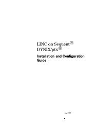
The external lock manager is primarily used for database locking. Database locking<br />
(Figure 1–1) supports a synchronized lock manager for use in multiple host systems.<br />
This is the function that the OS 2200 uses to enable a single application to execute<br />
simultaneously on multiple Dorado Series servers while accessing a common<br />
database. Separate locking interfaces <strong>and</strong> support are provided for use by Exec/TIP<br />
FCSS <strong>and</strong> the Universal Data <strong>System</strong> (UDS). It provides capabilities to lock <strong>and</strong><br />
unlock various database structures (such as pages). This capability is referred to in<br />
some documentation as RLP locking.<br />
The external lock manager can also be used by the MHFS feature to manage locks<br />
associated with the coordination <strong>and</strong> control of shared files.<br />
1–2 6885 3522–003
Figure 1–1. <strong>System</strong> Level Database Locking Provided by the <strong>XPC</strong>-L<br />
• Operating system interhost messaging<br />
Introduction<br />
Operating system interhost messaging supports communications among hosts in a<br />
multiple host environment. The mechanism provides a low volume interface using<br />
small packets of message data for the transfer of information in processes such as<br />
host <strong>and</strong> file status communication.<br />
• Shared Unit Duplexing synchronization<br />
<strong>XPC</strong>-L<br />
Locks for Application Group n<br />
Host Host Host<br />
Application<br />
Group n<br />
Application<br />
Group n<br />
Data for<br />
Application<br />
Group n<br />
Shared Unit Duplexing synchronization provides a record of the I/Os in progress to<br />
duplexed shared devices. All hosts in the MHFS environment have access to the<br />
synchronization tables so that any surviving host can synchronize the data in<br />
duplexed shared files if another host in the MHFS environment should stop.<br />
<strong>XPC</strong>-L <strong>and</strong> Multi-Host File Sharing (MHFS)<br />
Application<br />
Group n<br />
The <strong>XPC</strong>-L enhances the MHFS feature <strong>and</strong> two software feature groupings that build on<br />
the MHFS feature.<br />
The MHFS feature is a separately orderable <strong>and</strong> separately installed software feature of<br />
OS 2200. MHFS provides the OS 2200 coordination <strong>and</strong> control required to allow<br />
multiple hosts to simultaneously access data residing in a set of shared mass storage<br />
devices (referred to as the shared device group). There is only one shared device group<br />
in an MHFS environment.<br />
6885 3522–003 1–3
Introduction<br />
The hosts in the MHFS environment communicate with each other to coordinate actions<br />
taken related to the shared devices, such as<br />
• Setting <strong>and</strong> clearing locks that protect shared files from simultaneous updates<br />
• Changes in the configuration of devices in the shared device group<br />
• Recovery information<br />
• Operational information, including messages or unsolicited keyins directed to other<br />
hosts<br />
• Host status<br />
The MHFS feature supports the following methods of communication among hosts in<br />
the MHFS environment:<br />
• The preferred MHFS interhost communication method is with the <strong>XPC</strong>-L. In this<br />
configuration, the <strong>XPC</strong>-L system manages the locks for all hosts <strong>and</strong> passes MHFS<br />
coordination <strong>and</strong> control information among hosts.<br />
• The alternate MHFS interhost communication method is with a network<br />
configuration. In a network MHFS configuration, an Ethernet LAN links all the hosts<br />
in the MHFS environment together. In a network MHFS configuration, lock<br />
information, as well as MHFS coordination <strong>and</strong> control information, is passed<br />
through the network to all hosts in the MHFS environment.<br />
• Another alternative MHFS interhost communication method is with the <strong>XPC</strong>. In this<br />
configuration, the <strong>XPC</strong> manages the locks for all hosts <strong>and</strong> passes MHFS<br />
coordination <strong>and</strong> control information among hosts.<br />
Unisys has two software feature groupings that build on the MHFS feature to extend the<br />
capabilities of the operating system: Partitioned Applications (PA) <strong>and</strong> Extended<br />
Transaction Capacity (XTC).<br />
1–4 6885 3522–003
<strong>XPC</strong>-L <strong>and</strong> Partitioned Applications (PA)<br />
Introduction<br />
The PA feature grouping allows two hosts in an MHFS environment to provide backup<br />
for each other. Each host runs its own set of Transaction Processing (TIP) or Universal<br />
Data <strong>System</strong> (UDS) application groups. The files in support of those application groups<br />
reside in the shared device group, but these cannot be accessed by more than one host<br />
at a time.<br />
The two hosts maintain communications with each other (called “heartbeat“) through<br />
the MHFS interhost communication mechanism. If a host fails, the surviving host<br />
automatically recovers <strong>and</strong> begins processing the application groups for the failed host.<br />
Using the MHFS feature to make the production files of each host accessible by both<br />
hosts is key to this feature.<br />
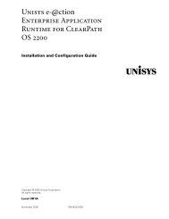
Figure 1–2 shows the configuration in a Partitioned Applications environment. For more<br />
information on the Partitioned Applications feature grouping, refer to the Partitioned<br />
Applications Conceptual Overview <strong>and</strong> the Partitioned Applications Planning, <strong>Installation</strong>,<br />
<strong>and</strong> Operations <strong>Guide</strong>.<br />
<strong>XPC</strong>-L<br />
Host A Host B<br />
Application Application<br />
Local<br />
Databases<br />
Local<br />
Disks<br />
Shared<br />
Databases<br />
Shared<br />
Disks<br />
Figure 1–2. <strong>Configuration</strong> for Partitioned Applications<br />
<strong>XPC</strong>-L <strong>and</strong> Extended Transaction Capacity (XTC)<br />
Local<br />
Databases<br />
Local<br />
Disks<br />
The XTC feature grouping enables several hosts in the MHFS environment to<br />
simultaneously execute transactions against the same TIP or UDS application group. The<br />
data files for the application group reside on the shared device group; this means that all<br />
hosts in the MHFS environment have access to them. The <strong>XPC</strong>-L system provides the<br />
locking mechanism that is required to allow multiple hosts to update shared databases.<br />
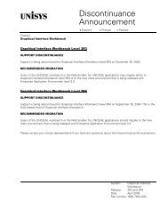
Figure 1–3 shows the configuration in an XTC environment with two hosts. For more<br />
information on the XTC feature grouping, refer to the Extended Transaction Capacity<br />
Planning, <strong>Migration</strong>, <strong>and</strong> Operations <strong>Guide</strong>.<br />
6885 3522–003 1–5
Introduction<br />
Figure 1–3. <strong>Configuration</strong> for XTC<br />
You can have either the Partitioned Applications feature grouping or the XTC feature<br />
grouping installed on your system, but not both.<br />
1.2.1. Hardware Components<br />
Multiple hosts connect to a redundant <strong>XPC</strong>-L system. The redundant <strong>XPC</strong>-L system<br />
consists of<br />
• A primary <strong>XPC</strong>-L Server platform<br />
• A secondary <strong>XPC</strong>-L Server platform<br />
• An active <strong>XPC</strong>-L Control Workstation<br />
<strong>XPC</strong>-L<br />
Record Lock<br />
Logic<br />
Host A Host B<br />
Local<br />
Databases<br />
Local<br />
Disks<br />
• One or more backup <strong>XPC</strong>-L Control Workstations<br />
• Connections between the various entities<br />
Application<br />
Shared<br />
Databases<br />
Shared<br />
Disks<br />
Local<br />
Databases<br />
Local<br />
Disks<br />
The primary <strong>and</strong> secondary platforms provide redundancy; they are used in a<br />
master/slave mode of operation. The role of master is initially assigned to the primary<br />
platform, but can change under software control while the system is in operation. The<br />
master <strong>XPC</strong>-L server is the server that actively provides the database locking <strong>and</strong><br />
interhost messaging functions. The slave <strong>XPC</strong>-L server provides backup if the master<br />
<strong>XPC</strong>-L server encounters an error condition.<br />
1–6 6885 3522–003
• Host platforms can be Dorado Series servers (or later).<br />
Introduction<br />
• Each <strong>XPC</strong>-L platform is an Intel cellular multiprocessing (CMP) platform. Redundancy<br />
is provided by using a second server <strong>and</strong> connecting it to the first. While the <strong>XPC</strong>-L<br />
servers are Dorado Series server platforms, their service processors do not perform<br />
any <strong>XPC</strong>-L functions. The service processor is used only for general CMP<br />
configuration <strong>and</strong> control functions. Refer to the ClearPath Plus Server Dorado 300<br />
Series Preinstallation <strong>and</strong> Planning <strong>Guide</strong> (Dorado 300 Series servers) or the<br />
ClearPath Plus Servers for OS 2200 Preinstallation Planning <strong>Guide</strong> (Dorado 200<br />
Series servers) for an overview of the Dorado Series server <strong>and</strong> the functions that<br />
the service processor provides.<br />
• The <strong>XPC</strong>-L Control Workstation platform is an Intel based computer. <strong>XPC</strong>-L Control is<br />
the primary operator interface to the <strong>XPC</strong>-L. Redundancy is provided by using more<br />
than one such workstation <strong>and</strong> networking both to the <strong>XPC</strong>-L servers with redundant<br />
LANs.<br />
1.2.2. Connections between Components<br />
Each host is connected to the primary <strong>and</strong> secondary <strong>XPC</strong>-L servers by a Virtual Interface<br />
(VI) channel (Figure 1–4). A VI channel consists of a pair of PCI cards connected by a fiber<br />
optic cable. One PCI card resides in an <strong>XPC</strong>-L server <strong>and</strong> the other in a host IOP. The<br />
host IOP with a VI channel PCI card installed is called an XIOP.<br />
The primary <strong>and</strong> secondary <strong>XPC</strong>-L servers connect to each other using VI channels<br />
(Figure 1–4). The active <strong>and</strong> backup <strong>XPC</strong>-L Control Workstations connect to each other<br />
through a private Ethernet network. The primary <strong>and</strong> secondary <strong>XPC</strong>-L servers also<br />
connect to this private Ethernet network for communication with the <strong>XPC</strong>-L Control<br />
Workstations.<br />
6885 3522–003 1–7
Introduction<br />
Request/status<br />
packet routing paths<br />
for 'reversed'<br />
configuration<br />
(slave on left,<br />
master on right)<br />
VI<br />
= VI Interface Channel<br />
Host A<br />
(2200)<br />
PCIOP PCIOP PCIOP PCIOP<br />
VI VI VI VI<br />
<strong>XPC</strong><br />
Master<br />
CMP<br />
Primary <strong>XPC</strong>-L<br />
Platform<br />
-<br />
(Intel Node)<br />
Primary/Secondary<br />
Crossover Paths<br />
Primary/Secondary<br />
Synchronization Paths<br />
Host D<br />
Secondary <strong>XPC</strong>-L<br />
Platform<br />
(Intel Node)<br />
Figure 1–4. <strong>XPC</strong>-L <strong>System</strong> Interconnections<br />
Request/status<br />
packet routing paths<br />
for configuration<br />
shown — routed by<br />
software<br />
Each host has paths to both the primary <strong>and</strong> secondary <strong>XPC</strong>-L <strong>and</strong> all paths can be used<br />
to send comm<strong>and</strong>s to <strong>XPC</strong>-L system. The server functioning as the master executes all<br />
<strong>XPC</strong>-L comm<strong>and</strong>s. Therefore, comm<strong>and</strong>s received by the slave must be sent to the<br />
master for execution. The crossover paths move comm<strong>and</strong> requests from the slave to<br />
the master <strong>and</strong>, at the completion of comm<strong>and</strong> execution, return status to the requester<br />
through the path connected to the slave.<br />
While the master server processes the comm<strong>and</strong>s, the slave <strong>XPC</strong>-L server monitors the<br />
operations of the master server. The slave server monitors the synchronization paths for<br />
audit requests, performs the data updates as directed by the master, <strong>and</strong> sends<br />
completion status when the data updates have been completed.<br />
In addition to providing the paths to be used to maintain data structure coherency, the<br />
synchronization paths are also used for general master/slave control functions—including<br />
memory size arbitration when the <strong>XPC</strong>-L system is started.<br />
1–8 6885 3522–003<br />
(2200)<br />
PCIOP PCIOP PCIOP PCIOP<br />
VI VI VI VI<br />
VI VI VI VI VI VI VI VI<br />
Active<br />
<strong>XPC</strong>-L Control<br />
Workstation<br />
VI<br />
VI<br />
VI<br />
VI<br />
VI VI<br />
VI VI<br />
VI VI<br />
VI<br />
VI<br />
VI<br />
VI<br />
VI<br />
VI<br />
Backup<br />
<strong>XPC</strong>-L<br />
Control<br />
Workstation<br />
Primary/Secondary<br />
Direct Connect paths<br />
-<br />
Private LAN<br />
<strong>XPC</strong>-L<br />
<strong>System</strong>
1.2.3. Software Components<br />
Introduction<br />
The hosts, <strong>XPC</strong>-L servers, <strong>and</strong> <strong>XPC</strong>-L Control Workstations run the following required or<br />
optional software:<br />
• OS 2200 host platforms run OS 2200/Exec software with the <strong>XPC</strong>EXEC feature. The<br />
<strong>XPC</strong>EXEC feature is a separately installed package for the Exec which must be<br />
ordered along with the <strong>XPC</strong>-L hardware. The following software components can<br />
use the <strong>XPC</strong>-L:<br />
− Multi-Host File Sharing (MHFS)<br />
− Partitioned Applications (PA)<br />
− Extended Transaction Capacity (XTC)<br />
• <strong>XPC</strong>-L Server platforms run Windows 2003, Enterprise Edition, <strong>and</strong> the <strong>XPC</strong>-L<br />
locking manager software.<br />
• <strong>XPC</strong>-L Control Workstation platforms run Windows XP Professional <strong>and</strong> the <strong>XPC</strong>-L<br />
Control software.<br />
The <strong>XPC</strong>-L Server software <strong>and</strong> the <strong>XPC</strong>-L Control software (including both versions of<br />
Microsoft Windows) are part of the <strong>XPC</strong>-L firmware release. Refer to the <strong>XPC</strong>-L <strong>System</strong><br />
Firmware 2.2 Customer Reference Manual for more information.<br />
6885 3522–003 1–9
Introduction<br />
1.3. Notation Conventions<br />
This manual uses the following typographical conventions for comm<strong>and</strong> formats,<br />
examples, <strong>and</strong> procedural discussions:<br />
Code<br />
User<br />
Comm<strong>and</strong>s <strong>and</strong> other characters that you must type in to activate<br />
the comm<strong>and</strong> are shown in this monospaced font, with variable<br />
information also being italicized. Information displayed by the<br />
system is also shown in this monospaced font, with variable<br />
information being italicized.<br />
Comm<strong>and</strong>s <strong>and</strong> other characters that you type in are shown in<br />
this monospaced font, with variable information also being<br />
italicized.<br />
interface References to specific menu items, icons, options, <strong>and</strong> most<br />
other user interface elements are shown in bold text (italicization<br />
is only to match the rest of the paragraph containing the term).<br />
Ctrl+Break A plus sign separates the labels of two or more keys to be<br />
pressed at the same time.<br />
[ ]<br />
{ }<br />
|<br />
Brackets indicate optional parameters or fields.<br />
Braces indicate two or more required parameters or fields from<br />
which you must choose one.<br />
A vertical line indicates a choice between two or more<br />
parameters, for example:<br />
parameter | parameter<br />
Note: Braces, brackets, <strong>and</strong> vertical lines are not part of the comm<strong>and</strong> syntax; do not<br />
type them in. Unless otherwise indicated, use blank spaces (one or more) to separate<br />
fields when you enter input.<br />
1–10 6885 3522–003
Section 2<br />
<strong>Installation</strong><br />
Software installation procedures vary, depending on the type of <strong>XPC</strong>-L system you<br />
ordered (see “2.1 Hardware <strong>Installation</strong>“). The installation information in this section<br />
consists primarily of references to existing documents <strong>and</strong> provides only those<br />
procedures that are unique to the <strong>XPC</strong>-L system.<br />
If you are unfamiliar with using an Intel node of a Dorado Series server, refer to any of<br />
the following documents for additional information:<br />
• ClearPath Plus Server Dorado 300 Series Install & Config Gd, Vol 5 Set Up OS 2200<br />
& Intel Part for Dorado 300 Series servers<br />
• ClearPath Plus Server Dorado Series Install & Config <strong>Guide</strong>, Vol 5: Set Up OS 2200 &<br />
Intel Part for Dorado 100 Series servers <strong>and</strong> Dorado 200 Series servers<br />
2.1. Hardware <strong>Installation</strong><br />
Figure 2–1 shows the major hardware components comprising an <strong>XPC</strong>-L system.<br />
The <strong>XPC</strong>-L system uses one or more Unisys Dorado Series servers running the Windows<br />
2003, Enterprise Edition operating system. The following are the available options when<br />
ordering an <strong>XPC</strong>-L system:<br />
• An <strong>XPC</strong>-L system that includes a Dorado Series server.<br />
Note: If you ordered an <strong>XPC</strong>-L system which included a Dorado Series server, all<br />
required platform hardware would have already been installed.<br />
• An <strong>XPC</strong>-L system that does not include a cabinet for the Dorado Series server <strong>and</strong><br />
where you use an existing Dorado Series server to house a single <strong>XPC</strong>-L server.<br />
6885 3522–003 2–1
<strong>Installation</strong><br />
If you ordered the above <strong>XPC</strong>-L system, refer to the following documents for the<br />
hardware platform installation procedure:<br />
• ClearPath Plus Server Dorado 300 Series Install & Config Gd, Vol 5 Set Up OS 2200<br />
& Intel Part for Dorado 300 Series servers<br />
• ClearPath Plus Server Dorado Series Install & Config <strong>Guide</strong>, Vol 5: Set Up OS 2200 &<br />
Intel Part for Dorado 100 Series servers <strong>and</strong> Dorado 200 Series servers<br />
2–2 6885 3522–003
E<br />
T<br />
H<br />
1<br />
E<br />
T<br />
H<br />
2<br />
Host A<br />
Primary<br />
<strong>XPC</strong>-L<br />
P-C01<br />
P-C02<br />
P-C03<br />
P-C04<br />
P-S01<br />
P-S02<br />
Active<br />
<strong>XPC</strong>-L<br />
Control<br />
Backup<br />
<strong>XPC</strong>-L<br />
Control<br />
Figure 2–1. Major Hardware Components<br />
Host B<br />
Secondary<br />
<strong>XPC</strong>-L<br />
<strong>Installation</strong><br />
PCIOP1-3 PCIOP1-4 PCIOP1-2 PCIOP1-1<br />
PCIOP2-2 PCIOP2-1 PCIOP2-3 PCIOP2-4<br />
P-DC04 P-DC03 P-DC02 P-DC01<br />
P-DC05 P-DC06 P-DC07 P-DC08<br />
PCIOP3-1 PCIOP3-2<br />
Host C<br />
PCIOP3-4<br />
PCIOP3-3<br />
HUB1<br />
P-S03<br />
P-S04<br />
P-C05<br />
P-C06<br />
P-C07<br />
P-C08<br />
LAN1 LAN2<br />
6885 3522–003 2–3<br />
S-C01<br />
S-C02<br />
S-C03<br />
S-C04<br />
S-S01<br />
S-S02<br />
S-S03<br />
S-S04<br />
S-C05<br />
S-C06<br />
S-C07<br />
S-C08<br />
HUB2<br />
LAN1 LAN2<br />
S-DC01 S-DC02 S-DC03 S-DC04<br />
S-DC08 S-DC07 S-DC06 S-DC05<br />
PCIOP4-4 PCIOP4-3<br />
Host D<br />
PCIOP4-1<br />
PCIOP4-2<br />
E<br />
T<br />
H<br />
1<br />
E<br />
T<br />
H<br />
2
<strong>Installation</strong><br />
2.1.1. Installing <strong>XPC</strong>-L Control Workstation Hardware<br />
The <strong>XPC</strong>-L Control Workstation hardware is a workstation supplied by Unisys with the<br />
appropriate hardware for supporting the operation of the <strong>XPC</strong>-L system. Unless<br />
otherwise directed by Unisys, do not change or modify any hardware on the <strong>XPC</strong>-L<br />
Control Workstation. Also, do not upgrade your <strong>XPC</strong>-L Control Workstation unless it is<br />
required to do so in the <strong>XPC</strong>-L Firmware 2.2 Customer Reference Manual or in the<br />
Technical Information Bulletin for an <strong>XPC</strong>-L system. Procedures for any required platform<br />
hardware updates are described in the documentation accompanying the <strong>XPC</strong>-L system<br />
firmware release.<br />
Documentation for installing the <strong>XPC</strong>-L Control Workstation is provided in the packaging<br />
from Dell. Connect the keyboard <strong>and</strong> monitor to the PC as documented.<br />
2.1.2. Installing <strong>XPC</strong>-L Server Hardware<br />
The <strong>XPC</strong>-L system hardware can be delivered by Unisys in two types. The system could<br />
include cabinetry with the Intel node installed in a Dorado Series server. Else, it could be<br />
shipped to your site as a st<strong>and</strong>-alone component, without the cabinet (except for<br />
Dorado 300 Series servers, which always include cabinetry). Initial installation depends<br />
on the type ordered <strong>and</strong> accordingly begins with one of the following two documentation<br />
sets:<br />
If the ordered <strong>XPC</strong>-L server style is<br />
• Installed as the Intel node of a Dorado 300 Series server, refer to the ClearPath Plus<br />
Server Dorado 300 Series Install & Config Gd Volumes 1 (Installing <strong>and</strong> Connecting<br />
Hardware), 2 (Setting Up Service Processors), 4 (Testing Hardware), 5 (Setting Up<br />
OS 2200 <strong>and</strong> Intel Partitions), <strong>and</strong> 6 (Completing <strong>Installation</strong> Tasks) for hardware<br />
installation procedures. Your system will arrive with the Intel partition connected to<br />
port 5 of the Monitor concentrator.<br />
2–4 6885 3522–003
Table 2–1. Intel Cabling Connections<br />
From To<br />
<strong>Installation</strong><br />
Name Port/Jack Name Port/Jack<br />
Intel Partition 1 Monitor<br />
Intel Partition 1 Keyboard<br />
Intel Partition 1 Mouse<br />
KVM9001301-CNV CAT5 Monitor<br />
Concentrator<br />
Monitor<br />
Concentrator<br />
Monitor<br />
Keyboard<br />
Mouse<br />
Back of the LCD tray<br />
on the left side (from<br />
the rear of the<br />
cabinet)<br />
Note: The Port/Jack column shows either port numbers or the labels of the jacks as they<br />
appear on the equipment. The following list provides additional information about the jacks:<br />
• CAT5 — Ethernet cable jack<br />
• Keyboard — PS/2 keyboard connector<br />
• Monitor — video connector<br />
• Mouse — PS/2 connector<br />
• Installed as the Intel node of a Dorado 200 Series host, refer to the ClearPath Plus<br />
Server Dorado Series Install & Config <strong>Guide</strong>, Vol 5: Set Up OS 2200 & Intel Part for<br />
hardware installation procedures.<br />
• Delivered as a st<strong>and</strong>-alone component, refer to the document Enterprise Servers<br />
Hardware <strong>Installation</strong> <strong>Guide</strong> hardware installation procedures. (This does not apply to<br />
Dorado 300 Series servers; they are not delivered as st<strong>and</strong>-alone components.)<br />
Follow the procedures in the appropriate hardware installation guide for insertion of new<br />
PCI connected devices to install the VI cards in the <strong>XPC</strong>-L server.<br />
2.1.3. Installing Host Hardware<br />
For the installation of your Dorado Series host, refer to the following documents:<br />
• ClearPath Plus Server Dorado 300 Series Install & Config Gd, Vol 5 Set Up OS 2200<br />
& Intel Part for Dorado 300 Series servers<br />
• ClearPath Plus Server Dorado Series Install & Config <strong>Guide</strong>, Vol 5: Set Up OS 2200 &<br />
Intel Part for Dorado 100 Series servers <strong>and</strong> Dorado 200 Series servers<br />
The only hardware components in a host unique to an <strong>XPC</strong>-L system are the VI cards <strong>and</strong><br />
the PCIOP (the XIOP).<br />
6885 3522–003 2–5<br />
5
<strong>Installation</strong><br />
For information on adding or replacing PCIOPs, refer to the following documents:<br />
• For connecting PCIOP cables<br />
− ClearPath Plus Server Dorado 300 Series Install & Config Gd, Vol 1 Installing &<br />
Connecting H/W for Dorado 300 Series servers<br />
− ClearPath Plus Server Dorado Series Install & Config <strong>Guide</strong> for CSR, Vol 3<br />
Installing & Connecting H/W for Dorado 100 Series servers <strong>and</strong> Dorado 200<br />
Series servers<br />
Note: Volume 3: Installing <strong>and</strong> Connecting Hardware is available only to Unisys<br />
representatives.<br />
• For PCIOP PCA/VI card installation<br />
− Dorado Series Fault Isolation <strong>and</strong> Servicing <strong>Guide</strong> (Dorado 100 Series servers<br />
<strong>and</strong> Dorado 200 Series servers)<br />
− Dorado 300 Series <strong>Installation</strong> <strong>and</strong> <strong>Configuration</strong> <strong>Guide</strong> for Customer Service<br />
Representatives Volume 1: Installing <strong>and</strong> Connecting Hardware (Dorado 300<br />
Series servers)<br />
2.1.4. Installing VI Cables<br />
A number of VI cables are supplied with your <strong>XPC</strong>-L system. Refer to Figure 2–1 <strong>and</strong> the<br />
appropriate part of the worksheet (see Table B–1 through Table B–7) supplied with your<br />
<strong>XPC</strong>-L system. Compare the locations of the VI cards in the PCI slots of your server to<br />
determine the overall VI card interconnections that are required. Refer to Table 2–2<br />
(Dorado 300 Series servers) or Table 2–3 (Dorado 200 Series servers) to cable your<br />
system; the factory might have already connected some of the cables.<br />
Table 2–2. VI Cabling for Dorado 300 Series Servers<br />
From... To...<br />
Name Location Name Location<br />
Primary <strong>XPC</strong>-L Server,<br />
DC01 Host A Path 1<br />
Primary <strong>XPC</strong>-L Server,<br />
C01 Host A Path 1<br />
Primary <strong>XPC</strong>-L Server,<br />
S01 Path 1<br />
Primary <strong>XPC</strong>-L Server,<br />
DC03 Host B Path 1<br />
Primary <strong>XPC</strong>-L Server,<br />
C03 Host B Path 1<br />
Primary <strong>XPC</strong>-L Server,<br />
DC02 Host A Path 2<br />
Cell 0, Bus 3 Host A, PCIOP1-1 Customer Unique<br />
Cell 0, Bus 4 Secondary <strong>XPC</strong>-L Server,<br />
C01 Host A Path 1<br />
Cell 0, Bus 5 Secondary <strong>XPC</strong>-L Server,<br />
S01 Path 1<br />
Cell 0, Bus 4<br />
Cell 0, Bus 5<br />
Cell 0, Bus 6 Host B, PCIOP2-1 Customer Unique<br />
Cell 0, Bus 7 Secondary <strong>XPC</strong>-L Server,<br />
C03 Host B Path 1<br />
Cell 0, Bus 7<br />
Cell 1, Bus 3 Host A, PCIOP1-2 Customer Unique<br />
2–6 6885 3522–003
Table 2–2. VI Cabling for Dorado 300 Series Servers<br />
From... To...<br />
<strong>Installation</strong><br />
Name Location Name Location<br />
Primary <strong>XPC</strong>-L Server,<br />
C02 Host A Path 2<br />
Primary <strong>XPC</strong>-L Server,<br />
S02 Path 2<br />
Primary <strong>XPC</strong>-L Server,<br />
DC04 Host B Path 2<br />
Primary <strong>XPC</strong>-L Server,<br />
C04 Host B Path 2<br />
Primary <strong>XPC</strong>-L Server,<br />
DC05 Host C Path 1<br />
Primary <strong>XPC</strong>-L Server,<br />
C05 Host C Path 1<br />
Primary <strong>XPC</strong>-L Server,<br />
S03 Path 3<br />
Primary <strong>XPC</strong>-L Server,<br />
DC07 Host D Path 1<br />
Primary <strong>XPC</strong>-L Server,<br />
C07 Host D Path 1<br />
Primary <strong>XPC</strong>-L Server,<br />
DC06 Host C Path 2<br />
Primary <strong>XPC</strong>-L Server,<br />
C06 Host C Path 2<br />
Primary <strong>XPC</strong>-L Server,<br />
S04 Path 4<br />
Primary <strong>XPC</strong>-L Server,<br />
DC08 Host D Path 2<br />
Primary <strong>XPC</strong>-L Server,<br />
C08 Host D Path 2<br />
Secondary <strong>XPC</strong>-L Server,<br />
DC01 Host A Path 3<br />
Secondary <strong>XPC</strong>-L Server,<br />
DC03 Host B Path 3<br />
Secondary <strong>XPC</strong>-L Server,<br />
DC02 Host A Path 4<br />
Secondary <strong>XPC</strong>-L Server,<br />
DC04 Host B Path 4<br />
Cell 1, Bus 4 Secondary <strong>XPC</strong>-L Server,<br />
C02 Host A Path 2<br />
Cell 1, Bus 5 Secondary <strong>XPC</strong>-L Server,<br />
S02 Path 2<br />
Cell 1, Bus 4<br />
Cell 1, Bus 5<br />
Cell 1, Bus 6 Host B, PCIOP2-2 Customer Unique<br />
Cell 1, Bus 7 Secondary <strong>XPC</strong>-L Server,<br />
C04 Host B Path 2<br />
Cell 1, Bus 7<br />
Cell 2, Bus 3 Host C, PCIOP3-1 Customer Unique<br />
Cell 2, Bus 4 Secondary <strong>XPC</strong>-L Server,<br />
C05 Host C Path 1<br />
Cell 2, Bus 5 Secondary <strong>XPC</strong>-L Server,<br />
S03 Path 3<br />
Cell 2, Bus 4<br />
Cell 2, Bus 5<br />
Cell 2, Bus 6 Host D, PCIOP4-1 Customer Unique<br />
Cell 2, Bus 7 Secondary <strong>XPC</strong>-L Server,<br />
C07 Host D Path 1<br />
Cell 2, Bus 7<br />
Cell 3, Bus 3 Host C, PCIOP3-2 Customer Unique<br />
Cell 3, Bus 4 Secondary <strong>XPC</strong>-L Server,<br />
C06 Host C Path 2<br />
Cell 3, Bus 5 Secondary <strong>XPC</strong>-L Server,<br />
S04 Path 4<br />
Cell 3, Bus 4<br />
Cell 3, Bus 5<br />
Cell 3, Bus 6 Host D, PCIOP4-2 Customer Unique<br />
Cell 3, Bus 7 Secondary <strong>XPC</strong>-L Server,<br />
C08 Host D Path 2<br />
Cell 3, Bus 7<br />
Cell 0, Bus 3 Host A, PCIOP1-3 Customer Unique<br />
Cell 0, Bus 6 Host B, PCIOP2-3 Customer Unique<br />
Cell 1, Bus 3 Host A, PCIOP1-4 Customer Unique<br />
Cell 1, Bus 6 Host B, PCIOP2-4 Customer Unique<br />
6885 3522–003 2–7
<strong>Installation</strong><br />
Table 2–2. VI Cabling for Dorado 300 Series Servers<br />
From... To...<br />
Name Location Name Location<br />
Secondary <strong>XPC</strong>-L Server,<br />
DC05 Host C Path 3<br />
Secondary <strong>XPC</strong>-L Server,<br />
DC07 Host D Path 3<br />
Secondary <strong>XPC</strong>-L Server,<br />
DC06 Host C Path 4<br />
Secondary <strong>XPC</strong>-L Server,<br />
DC08 Host D Path 4<br />
Cell 2, Bus 3 Host C, PCIOP3-3 Customer Unique<br />
Cell 2, Bus 6 Host D, PCIOP4-3 Customer Unique<br />
Cell 3, Bus 3 Host C, PCIOP3-4 Customer Unique<br />
Cell 3, Bus 6 Host D, PCIOP4-4 Customer Unique<br />
Table 2–3. VI Cabling for Dorado 200 Series Servers<br />
From... To...<br />
Name Location Name Location<br />
Primary <strong>XPC</strong>-L Server,<br />
DC05 Host C Path 1<br />
Primary <strong>XPC</strong>-L Server,<br />
DC01 Host A Path 1<br />
Primary <strong>XPC</strong>-L Server,<br />
DC07 Host D Path 1<br />
Primary <strong>XPC</strong>-L Server,<br />
DC03 Host B Path 1<br />
Primary <strong>XPC</strong>-L Server,<br />
DC06 Host C Path 2<br />
Primary <strong>XPC</strong>-L Server,<br />
DC02 Host A Path 2<br />
Primary <strong>XPC</strong>-L Server,<br />
DC08 Host D Path 2<br />
Primary <strong>XPC</strong>-L Server,<br />
DC04 Host B Path 2<br />
Primary <strong>XPC</strong>-L Server,<br />
C05 Host C Path 3<br />
Primary <strong>XPC</strong>-L Server,<br />
C01 Host A Path 3<br />
Primary <strong>XPC</strong>-L Server,<br />
C07 Host D Path 3<br />
Pod 0<br />
DIB-0-1-0<br />
Pod 0<br />
DIB-0-1-1<br />
Pod 0<br />
DIB-0-1-2<br />
Pod 0<br />
DIB-0-1-3<br />
Pod 0<br />
DIB-1-1-0<br />
Pod 0<br />
DIB-1-1-1<br />
Pod 0<br />
DIB-1-1-2<br />
Pod 0<br />
DIB-1-1-3<br />
Pod 2<br />
DIB-0-1-0<br />
Pod 2<br />
DIB-0-1-1<br />
Pod 2<br />
DIB-0-1-2<br />
Host C, PCIOP3-1 Customer<br />
Unique<br />
Host A, PCIOP1-1 Customer<br />
Unique<br />
Host D, PCIOP4-1 Customer<br />
Unique<br />
Host B, PCIOP2-1 Customer<br />
Unique<br />
Host C, PCIOP3-2 Customer<br />
Unique<br />
Host A, PCIOP1-2 Customer<br />
Unique<br />
Host D, PCIOP4-2 Customer<br />
Unique<br />
Host B, PCIOP2-2 Customer<br />
Unique<br />
Secondary <strong>XPC</strong>-L Server,<br />
C05 Host C Path 3<br />
Secondary <strong>XPC</strong>-L Server,<br />
C01 Host A Path 3<br />
Secondary <strong>XPC</strong>-L Server,<br />
C07 Host D Path 3<br />
Pod 2<br />
DIB-0-1-0<br />
Pod 2<br />
DIB-0-1-1<br />
Pod 2<br />
DIB-0-1-2<br />
2–8 6885 3522–003
Table 2–3. VI Cabling for Dorado 200 Series Servers<br />
From... To...<br />
<strong>Installation</strong><br />
Name Location Name Location<br />
Primary <strong>XPC</strong>-L Server,<br />
C03 Host B Path 3<br />
Primary <strong>XPC</strong>-L Server,<br />
S01 Path 1<br />
Primary <strong>XPC</strong>-L Server,<br />
S03 Path 3<br />
Primary <strong>XPC</strong>-L Server,<br />
C06 Host C Path 4<br />
Primary <strong>XPC</strong>-L Server,<br />
C02 Host A Path 4<br />
Primary <strong>XPC</strong>-L Server,<br />
C08 Host D Path 4<br />
Primary <strong>XPC</strong>-L Server,<br />
C04 Host B Path 4<br />
Primary <strong>XPC</strong>-L Server,<br />
S02 Path 2<br />
Primary <strong>XPC</strong>-L Server,<br />
S04 Path 4<br />
Secondary <strong>XPC</strong>-L Server,<br />
DC05 Host C Path 3<br />
Secondary <strong>XPC</strong>-L Server,<br />
DC01 Host A Path 3<br />
Secondary <strong>XPC</strong>-L Server,<br />
DC07 Host D Path 3<br />
Secondary <strong>XPC</strong>-L Server,<br />
DC03 Host B Path 3<br />
Secondary <strong>XPC</strong>-L Server,<br />
DC06 Host C Path 4<br />
Secondary <strong>XPC</strong>-L Server,<br />
DC02 Host A Path 4<br />
Secondary <strong>XPC</strong>-L Server,<br />
DC08 Host D Path 4<br />
Secondary <strong>XPC</strong>-L Server,<br />
DC04 Host B Path 4<br />
Pod 2<br />
DIB-0-1-3<br />
Pod 2<br />
DIB-0-2-1<br />
Pod 2<br />
DIB-0-2-3<br />
Pod 2<br />
DIB-1-1-0<br />
Pod 2<br />
DIB-1-1-1<br />
Pod 2<br />
DIB-1-1-2<br />
Pod 2<br />
DIB-1-1-3<br />
Pod 2<br />
DIB-1-2-1<br />
Pod 2<br />
DIB-1-2-3<br />
Pod 0<br />
DIB-0-1-0<br />
Pod 0<br />
DIB-0-1-1<br />
Pod 0<br />
DIB-0-1-2<br />
Pod 0<br />
DIB-0-1-3<br />
Pod 0<br />
DIB-1-1-0<br />
Pod 0<br />
DIB-1-1-1<br />
Pod 0<br />
DIB-1-1-2<br />
Pod 0<br />
DIB-1-1-3<br />
Secondary <strong>XPC</strong>-L Server,<br />
C03 Host B Path 3<br />
Secondary <strong>XPC</strong>-L Server,<br />
S01 Path 1<br />
Secondary <strong>XPC</strong>-L Server,<br />
S03 Path 3<br />
Secondary <strong>XPC</strong>-L Server,<br />
C06 Host C Path 4<br />
Secondary <strong>XPC</strong>-L Server,<br />
C02 Host A Path 4<br />
Secondary <strong>XPC</strong>-L Server,<br />
C08 Host D Path 4<br />
Secondary <strong>XPC</strong>-L Server,<br />
C04 Host B Path 4<br />
Secondary <strong>XPC</strong>-L Server,<br />
S02 Path 2<br />
Secondary <strong>XPC</strong>-L Server,<br />
S04 Path 4<br />
Pod 2<br />
DIB-0-1-3<br />
Pod 2<br />
DIB-0-2-1<br />
Pod 2<br />
DIB-0-2-3<br />
Pod 2<br />
DIB-1-1-0<br />
Pod 2<br />
DIB-1-1-1<br />
Pod 2<br />
DIB-1-1-2<br />
Pod 2<br />
DIB-1-1-3<br />
Pod 2<br />
DIB-1-2-1<br />
Pod 2<br />
DIB-1-2-3<br />
Host C, PCIOP3-3 Customer<br />
Unique<br />
Host A, PCIOP1-3 Customer<br />
Unique<br />
Host D, PCIOP4-3 Customer<br />
Unique<br />
Host B, PCIOP2-3 Customer<br />
Unique<br />
Host C, PCIOP3-4 Customer<br />
Unique<br />
Host A, PCIOP1-4 Customer<br />
Unique<br />
Host D, PCIOP4-4 Customer<br />
Unique<br />
Host B, PCIOP2-4 Customer<br />
Unique<br />
6885 3522–003 2–9
<strong>Installation</strong><br />
Figure 2–2 shows how to connect an individual VI cable to a VI card. The connectors are<br />
keyed to prevent misalignment or inversion. When inserting the cable, an audible click<br />
should be heard from the connector when it snaps into place.<br />
Figure 2–2. Fiber-Optic Cable Connectors<br />
After connecting a cable to a VI card, use the appropriate label supplied with your <strong>XPC</strong>-L<br />
system to indicate what this end of the cable connects to (for example, Host A, Path 1).<br />
Apply the label to the cable such that it is visible without disconnecting the cable.<br />
2.1.5. Installing Ethernet Cables <strong>and</strong> Hubs<br />
A number of Ethernet cables are supplied along with your <strong>XPC</strong>-L system. One or more<br />
Ethernet hubs might be also be included. Refer to Figure 2–1 <strong>and</strong> the appropriate part of<br />
the worksheet (see Table B–1 through Table B–7) supplied with your <strong>XPC</strong>-L system to<br />
determine the overall Ethernet card <strong>and</strong> hub interconnections that are required. Refer to<br />
Table 2–4 (Dorado 300 Series servers) or Table 2–5 (Dorado 200 Series servers) to cable<br />
your system; the factory might have already connected some of the cables.<br />
The Ethernet equipment provided with your <strong>XPC</strong>-L system is st<strong>and</strong>ard Ethernet<br />
hardware (refer to the appropriate Dorado Series manuals if you are unfamiliar with<br />
Ethernet equipment). Set up the connections between the Ethernet cards <strong>and</strong> hubs as<br />
indicated. After connecting a cable to an Ethernet card or hub, use the appropriate label<br />
supplied with your <strong>XPC</strong>-L system to indicate what this end of the cable connects to (for<br />
example, <strong>XPC</strong>-L Control Workstation 1, LAN 1). Apply the label to the cable such that it is<br />
visible without disconnecting the cable.<br />
In a redundant configuration, it is important to connect things properly. The Ethernet 1<br />
connections from each <strong>XPC</strong>-L server must connect to HUB1. Similarly, the Ethernet 2<br />
connections from each <strong>XPC</strong>-L server must connect to HUB2. If you are using Dorado 300<br />
Series servers, the Ethernet 1 connection is on cell 0 (LAN 0) <strong>and</strong> the Ethernet2<br />
connection is on cell 1 (LAN 4). The LAN1 connections from each <strong>XPC</strong>-L Control<br />
Workstation must connect to HUB1. The LAN2 connections from each <strong>XPC</strong>-L Control<br />
Workstation must connect to HUB2.<br />
The Ethernet hubs supplied with your <strong>XPC</strong>-L system must not be confused with or<br />
connected to any other Dorado Series server networking equipment (for example,<br />
Dorado Series server maintenance processor LAN). The maintenance processor LAN<br />
must be configured as a separate Ethernet network.<br />
2–10 6885 3522–003
<strong>Installation</strong><br />
The Ethernet card designated as part of the maintenance system can be used with the<br />
Dorado Series server maintenance processor LAN for things such as support for Call<br />
Home. The <strong>XPC</strong>-L Ethernet cards are separate <strong>and</strong> distinct from the Ethernet card used<br />
for maintenance.<br />
The Ethernet managed switch (NG700-SWX) used for the <strong>XPC</strong>-L Control Workstation<br />
interconnect is the same as that used in the <strong>XPC</strong>-L (Dorado 300 Series servers) for<br />
hardware control. However, when used for <strong>XPC</strong>-L Control Workstation interconnect, the<br />
switch is used as a simple switch rather than as a managed switch. All management<br />
programming is removed from the switch by forcing a factory reset: momentarily press<br />
the Factory Reset button located on the back of the unit, then cycle the AC power<br />
switch to OFF <strong>and</strong> then to ON again.<br />
Table 2–4. Ethernet Cabling for Dorado 300 Series Servers<br />
From... To...<br />
Name Location Name Location<br />
Hub 1 Port 1 Primary <strong>XPC</strong>-L Server<br />
(Ethernet 1)<br />
Hub 1 Port 2 Secondary <strong>XPC</strong>-L Server<br />
(Ethernet 1)<br />
Hub 1 Port 3 Active <strong>XPC</strong>-L Control PC<br />
(LAN 1)<br />
Hub 1 Port 4 Backup <strong>XPC</strong>-L Control PC<br />
(LAN 1)<br />
Hub 2 Port 1 Primary <strong>XPC</strong>-L Server<br />
(Ethernet 2)<br />
Hub 2 Port 2 Secondary <strong>XPC</strong>-L Server<br />
(Ethernet 2)<br />
Hub 2 Port 3 Active <strong>XPC</strong>-L Control PC<br />
(LAN 2)<br />
Hub 2 Port 4 Backup <strong>XPC</strong>-L Control PC<br />
(LAN 2)<br />
Primary Server<br />
Control LAN 0<br />
Secondary<br />
Server Control<br />
LAN 0<br />
Port 15 Maintenance LAN 0<br />
Primary Server<br />
Port 15 Maintenance LAN 0<br />
Secondary Server<br />
Cell 0, Left Server LAN Port<br />
Cell 0, Left Server LAN Port<br />
On-board Ethernet<br />
On-board Ethernet<br />
Cell 1, Left Server LAN Port<br />
Cell 1, Left Server LAN Port<br />
Add-In Card Ethernet<br />
Add-In Card Ethernet<br />
Cell 0, right h<strong>and</strong> LAN port<br />
Cell 0, right h<strong>and</strong> LAN port<br />
6885 3522–003 2–11
<strong>Installation</strong><br />
Table 2–5. Ethernet Cabling for Dorado 200 Series Servers<br />
From... To...<br />
Name Location Name Location<br />
Hub 1 Port 1 Primary <strong>XPC</strong>-L Server<br />
(Ethernet 1)<br />
Hub 1 Port 2 Secondary <strong>XPC</strong>-L Server<br />
(Ethernet 1)<br />
Hub 1 Port 3 Active <strong>XPC</strong>-L Control PC<br />
(LAN 1)<br />
Hub 1 Port 4 Backup <strong>XPC</strong>-L Control<br />
PC<br />
(LAN 1)<br />
Hub 2 Port 1 Primary <strong>XPC</strong>-L Server<br />
(Ethernet 2)<br />
Hub 2 Port 2 Secondary <strong>XPC</strong>-L Server<br />
(Ethernet 2)<br />
Hub 2 Port 3 Active <strong>XPC</strong>-L Control PC<br />
(LAN 2)<br />
Hub 2 Port 4 Backup <strong>XPC</strong>-L Control<br />
PC<br />
(LAN 2)<br />
Primary<br />
Service<br />
Processor<br />
Maintenance<br />
LAN<br />
Secondary<br />
Service<br />
Processor<br />
Maintenance<br />
LAN<br />
Any open<br />
port<br />
Any open<br />
port<br />
Primary <strong>XPC</strong>-L Server<br />
(Maintenance Ethernet)<br />
Secondary <strong>XPC</strong>-L Server<br />
(Maintenance Ethernet)<br />
POD 0, DIB 0,<br />
SubDIB 2, Slot 3<br />
POD 0, DIB 0,<br />
SubDIB 2, Slot 3<br />
On-board Ethernet<br />
On-board Ethernet<br />
POD 0, DIB 1,<br />
SubDIB 2, Slot 3<br />
POD 0, DIB 1,<br />
SubDIB 2, Slot 3<br />
Add-In Card Ethernet<br />
Add-In Card Ethernet<br />
POD 0, DIB 1,<br />
SubDIB 2, Slot 1<br />
POD 0, DIB 1,<br />
SubDIB 2, Slot 1<br />
2–12 6885 3522–003
2.2. Software <strong>Installation</strong><br />
Software installation consists of two parts:<br />
• <strong>Installation</strong> of platform software<br />
• <strong>Installation</strong> of <strong>XPC</strong>-L software<br />
2.2.1. Installing Platform Software<br />
<strong>Installation</strong><br />
Before beginning the <strong>XPC</strong>-L software installation, you need to have installed the hosts,<br />
servers, <strong>and</strong> workstations that would comprise your <strong>XPC</strong>-L system. Doing these includes<br />
connecting them together <strong>and</strong> booting them.<br />
<strong>Installation</strong> of the hardware <strong>and</strong> default software is covered in the documentation<br />
specific to the host, server, <strong>and</strong> workstation. All default Windows software must be<br />
available on the <strong>XPC</strong>-L Control Workstations <strong>and</strong> similarly all default Dorado Series server<br />
software on the <strong>XPC</strong>-L servers.<br />
2.2.1.1. Installing Platform Software on the <strong>XPC</strong>-L Control<br />
Workstations<br />
All default Windows software is required on the <strong>XPC</strong>-L Control Workstations.<br />
The <strong>XPC</strong>-L Control Workstation supplied with your <strong>XPC</strong>-L system has Windows XP<br />
Professional already loaded. This subsection describes how to complete the installation<br />
of the operating system <strong>and</strong> also how to configure the workstation for local use. Perform<br />
these procedures for the active <strong>XPC</strong>-L Control Workstation <strong>and</strong> for any backup <strong>XPC</strong>-L<br />
Control Workstation supplied with your <strong>XPC</strong>-L system.<br />
Installing Windows XP<br />
Perform the following steps to complete installation of the operating system <strong>and</strong> to enter<br />
the user names <strong>and</strong> passwords for this workstation.<br />
Note: A customer representative must accept software license agreements; a Unisys<br />
service representative cannot perform these functions.<br />
1. Turn on the workstation. The system boots <strong>and</strong> the Windows XP Setup Wizard<br />
appears.<br />
2. Click Next.<br />
The End User Software License Agreement window appears.<br />
3. Request the customer's representative to perform the following steps to accept the<br />
End User License Agreements (EULA):<br />
a. Read the license agreements, scrolling as necessary.<br />
b. Select the I accept the agreement check box for each EULA <strong>and</strong> then click<br />
Next.<br />
The Regional <strong>and</strong> Language Options dialog box appears.<br />
6885 3522–003 2–13
<strong>Installation</strong><br />
4. Click Next.<br />
The Personalize Your Software dialog box appears.<br />
5. Type in your name <strong>and</strong> the name of your company or organization <strong>and</strong> click Next.<br />
A dialog box appears in which you enter the product key for Windows XP operating<br />
system.<br />
6. Type in the product key <strong>and</strong> click Next.<br />
Note: For the OptiPlex 755 <strong>and</strong> 960 workstations, you may have to use an XP<br />
product key from one of the service processors or any PC that has an XP product<br />
key. Please refer to “Windows XP Activation“ of this section for an explanation of<br />
this procedure.<br />
7. Use the <strong>XPC</strong>-L <strong>System</strong> Information part of the worksheet provided with your system<br />
(see Table B–8 for an example of this table) to respond to the resulting What’s<br />
your computer name? message.<br />
• Type the Computer Name from the appropriate row of the <strong>XPC</strong>-L <strong>System</strong><br />
Information part of the worksheet provided with your system into the Name<br />
box.<br />
• Type a password of your choice into the Password box.<br />
• Set the Date, Time, <strong>and</strong> Time Zone boxes appropriately.<br />
• Click Next.<br />
The Network Settings dialog box appears.<br />
8. Select the Typical option <strong>and</strong> click Next.<br />
The Workgroup or Computer Domain dialog box appears.<br />
9. Select the No option (this selects Workgroup) <strong>and</strong> click Next.<br />
The system performs the final set up tasks, <strong>and</strong> displays Completing the Window XP<br />
Setup Wizard.<br />
10. Click FINISH.<br />
The system reboots.<br />
Setting up Network <strong>Configuration</strong>s<br />
Perform the following steps to configure <strong>and</strong> set up the network configurations. The<br />
workstation has two Ethernet ports installed.<br />
The onboard Ethernet port is LAN2 when looking at the Microsoft Network Connections<br />
window <strong>and</strong> must be configured with the Network IP address 1 shown in Table B–8. The<br />
port provided by the PCI Ethernet card is simply LAN when looking at the Microsoft<br />
Network Connections window <strong>and</strong> must be configured with the Network IP address 2<br />
shown in Table B–8.<br />
2–14 6885 3522–003
1. On the Start menu, point to settings <strong>and</strong> click Control Panel.<br />
2. Double-click the Network <strong>and</strong> Internet connections category.<br />
<strong>Installation</strong><br />
The Network <strong>and</strong> Internet connections window appears. There are two parts to this<br />
window; the top part has the caption Pick a task <strong>and</strong> the lower part has the<br />
caption or pick a Control Panel Icon with labeled icons below it.<br />
3. On the lower part of the window, click Network Connections. The Network<br />
Connections window appears.<br />
4. Right-click the appropriate Local Area Connection icon <strong>and</strong> click Properties.<br />
The Local Area Connection Properties window appears.<br />
5. Click Internet Protocol (TCP/IP) to highlight it.<br />
6. Click Properties.<br />
The Internet Protocol (TCP/IP) Properties dialog box appears.<br />
7. Click Use the following IP address <strong>and</strong> fill in the boxes as follows:<br />
a. Type the IP address for this workstation. Also write it into the appropriate row<br />
<strong>and</strong> column of the <strong>XPC</strong>-L <strong>System</strong> Information part of the worksheet provided<br />
with your system (see Table B–8 for an example of this table).<br />
b. Type the appropriate Subnet mask.<br />
c. Leave the boxes Default gateway, DNS server, <strong>and</strong> Alternate DNS<br />
server blank.<br />
d. Click OK to close the Internet Protocol (TCP/IP) Properties window.<br />
8. Click Close to close the Local Area Connection Properties window.<br />
9. Repeat steps 4 through 8 for the other network card (the other Local Area<br />
Connection icon).<br />
10. Close Control Panel.<br />
Windows XP Activation<br />
The Dell OptiPlex 755 <strong>and</strong> 960 workstations that are shipped as Control Workstations for<br />
the <strong>XPC</strong>-L have Windows XP SP2 installed. These workstations are setup at the Unisys<br />
factory for use as <strong>XPC</strong>-L Control Workstations. The most recently shipped OptiPlex 755<br />
<strong>and</strong> 960 workstations have a software option to downgrade from Windows Vista<br />
Business Bonus-Windows XP Professional.<br />
After you downgrade to Windows XP, you will no longer be able to activate the XP<br />
software over the Internet. When prompted to activate, call the activation support<br />
number <strong>and</strong> speak to the customer service representative who will help you activate the<br />
Windows XP software.<br />
Before you call the activation support number, ensure that you have the Windows XP CD<br />
<strong>and</strong> the XP product key from one of your existing workstations or service processors.<br />
You might be asked for the product key to activate the <strong>XPC</strong>-L workstation.<br />
6885 3522–003 2–15
<strong>Installation</strong><br />
2.2.1.2. Creating Partitions on the <strong>XPC</strong>-L Servers<br />
The <strong>XPC</strong>-L software runs in a hardware partition with a specific configuration. Perform<br />
the following steps on each server to create <strong>and</strong> configure an <strong>XPC</strong>-L partition.<br />
Note: If you ordered an <strong>XPC</strong>-L system that included a cabinet for the Dorado Series<br />
server, the hardware partition profiles would have already been installed.<br />
Dorado 300 Series Servers<br />
Using Server Sentinel, install PartitionX (where X is the partition number, 0 through 9).<br />
For instructions on creating <strong>and</strong> configuring partitions, refer to the Server Sentinel User's<br />
<strong>Guide</strong> <strong>and</strong> Task Help.<br />
Activate the partitions <strong>and</strong> enable each of the PCI buses needed for your system. Refer<br />
to the worksheet supplied with your system (Appendix B, “Example <strong>XPC</strong>-L Server PCI<br />
Locations Charts <strong>and</strong> Worksheets“ contains a sample of this worksheet).<br />
Note: Due to an existing Windows problem, PCI bus 1 must be up in all cells before<br />
booting the server.<br />
Dorado 200 Series Servers<br />
Perform the following steps <strong>and</strong> use the partition profiles provided on the <strong>XPC</strong>-L<br />
Firmware CD.<br />
1. Insert the <strong>XPC</strong>-L Firmware CD (which contains the <strong>XPC</strong>-L installation application) into<br />
the CD-ROM drive of the Service Processor of the Dorado Series server being used<br />
as the <strong>XPC</strong>-L server <strong>and</strong> cancel the installation program that starts automatically.<br />
2. Refer to the appropriate part of the worksheet (see Table B–1 through Table B–7)<br />
supplied with your <strong>XPC</strong>-L system; compare the locations of the VI cards in the PCI<br />
slots of your server to determine whether the <strong>XPC</strong>-L partition is in pod 0/ , 2 (lower<br />
profile) or in pod 1, 3 (upper profile).<br />
3. Copy the /PartitionProfiles directory from the CD to the C:\ drive on the Dorado<br />
Series server Service Processor <strong>and</strong> install the appropriate profile (<strong>XPC</strong>LLower.ptn or<br />
<strong>XPC</strong>LUpper.ptn) to the /PartitionProfiles directory. Repeat this for each Service<br />
Processor (master <strong>and</strong> slave).<br />
4. Use Server Sentinel to activate the partition <strong>XPC</strong>LLower for each of your <strong>XPC</strong>-L<br />
servers. Enable each of the DIBs <strong>and</strong> SubDIBs needed for you system. Refer to the<br />
appropriate part of the worksheet (see Table B–1 through Table B–7) supplied with<br />
your <strong>XPC</strong>-L system <strong>and</strong> compare the locations of the cards in the PCI slots of your<br />
server.<br />
2–16 6885 3522–003
Notes:<br />
This applies to Dorado 200 Series servers only.<br />
<strong>Installation</strong><br />
• You must use the appropriate partition profile provided on the release media. These<br />
profiles work for all installations. Contact Unisys if you think that the delivered files<br />
will not work with your installation.. Do not attempt to create or use partition profiles<br />
other than those delivered.<br />
• The partition profiles provided on the release media configure all possible PCI buses<br />
<strong>and</strong> bridges. During initialization, the system displays an error message for each<br />
component not found. Verify that each component identified as not being found<br />
really does not exist at your installation.<br />
Refer to the appropriate Server Sentinel documentation for specific information about<br />
creating partitions on the <strong>XPC</strong>-L servers.<br />
2.2.1.3. Installing Platform Software on the <strong>XPC</strong>-L Servers<br />
All default Dorado Series server software is required on the <strong>XPC</strong>-L servers.<br />
The <strong>XPC</strong>-L system uses one or more Dorado Series servers running the Windows 2003,<br />
Enterprise Edition, operating system. You have the following general options when<br />
ordering an <strong>XPC</strong>-L system:<br />
• An <strong>XPC</strong>-L system that includes a Dorado Series server with cabinet.<br />
• An <strong>XPC</strong>-L system that does not include a cabinet for the Dorado Series server,<br />
where you will use an existing Dorado Series server to house one <strong>XPC</strong>-L server.<br />
<strong>XPC</strong>-L Server with Cabinet<br />
If you ordered an <strong>XPC</strong>-L system which included a Dorado Series server with cabinet,<br />
most of the software would have already been installed. Perform the following steps to<br />
install the rest of the server platform software.<br />
Note: The mouse is disabled; Use the tab key to move through the available fields <strong>and</strong><br />
buttons.<br />
1. Start the <strong>XPC</strong>-L Partition from Server Sentinel.<br />
The system boots <strong>and</strong> the Windows Setup Wizard appears.<br />
2. Press the tab key to go to Next <strong>and</strong> press Enter.<br />
6885 3522–003 2–17
<strong>Installation</strong><br />
3. When the End User Software License Agreement appears, request a representative<br />
of the customer to perform the following steps to accept the End User License<br />
Agreements (EULA):<br />
a. Read the license agreements, using the Page Up <strong>and</strong> Page Down keys to<br />
scroll as necessary.<br />
b. Click I accept the agreement for each EULA <strong>and</strong> then press the tab key to<br />
select Next <strong>and</strong> press Enter.<br />
The Regional <strong>and</strong> Language Options dialog box appears.<br />
Note: A customer representative must accept software license agreements; a<br />
Unisys service representative cannot perform these functions.<br />
4. Press Enter.<br />
The Personalize Your Software dialog box appears.<br />
5. Type your name <strong>and</strong> the name of your company or organization, then select Next<br />
using the tab key <strong>and</strong> press Enter.<br />
The Licensing Modes dialog box appears.<br />
6. Press Enter.<br />
7. Use the <strong>XPC</strong>-L <strong>System</strong> Information part of the worksheet provided with your system<br />
(see Table B–8 for an example of this table) to respond to the resulting computer<br />
name <strong>and</strong> password display.<br />
− Type the name written in the appropriate row under the Computer Name column<br />
of the worksheet into the Name box.<br />
− Type a password of your choice in the Password box.<br />
8. Set the Date, Time, <strong>and</strong> Time Zone fields appropriately.<br />
9. Select Next using the tab key <strong>and</strong> press Enter.<br />
The Network Settings dialog box appears.<br />
10. Select the Typical option, then select Next using the tab key <strong>and</strong> press Enter.<br />
The Workgroup or Computer Domain dialog box appears.<br />
11. Select the No option to select Workgroup.<br />
12. Select Next using the tab key <strong>and</strong> press Enter.<br />
13. Select FINISH using the tab key <strong>and</strong> press Enter.<br />
The system reboots.<br />
14. After the <strong>XPC</strong>-L server reboots, log on as administrator so you can configure the<br />
maintenance LAN IP address for Call Home.<br />
15. On the Start menu, point to settings <strong>and</strong> click Control Panel.<br />
2–18 6885 3522–003
16. Double-click the Network <strong>and</strong> Internet connections category.<br />
<strong>Installation</strong><br />
The Network <strong>and</strong> Internet connections window appears. This window consists of<br />
two parts; the top part has the caption Pick a task <strong>and</strong> the lower part has the<br />
caption or pick a Control Panel icon with labeled icons below it.<br />
17. On the lower part of the window, click Network Connections. The Network<br />
Connections window appears.<br />
18. Click Start, point to Settings <strong>and</strong> select Network Connections.<br />
19. Right-click the LAN connection labeled LAN2 <strong>and</strong> select Properties.<br />
20. Click Internet Protocol (TCP/IP) to highlight it.<br />
21. Click Properties.<br />
The Internet Protocol (TCP/IP) Properties dialog box appears.<br />
22. Type the IP address for the appropriate <strong>XPC</strong>-L server <strong>and</strong> <strong>XPC</strong>-L platform referring to<br />
Table B–8.<br />
23. Type the appropriate subnet mask.<br />
24. Leave the boxes Default gateway, DNS server, <strong>and</strong> Alternate DNS server<br />
blank.<br />
25. Click OK to close the Internet Protocol (TCP/IP) Properties window.<br />
26. Click Close to close the Local Area Connection Properties window.<br />
27. Close Control Panel.<br />
<strong>XPC</strong>-L Server without Cabinet<br />
If you ordered an <strong>XPC</strong>-L system which does not include a cabinet for the Dorado Series<br />
server, where you will use an existing Dorado Series server to house one <strong>XPC</strong>-L Server,<br />
refer to the appropriate documents in the following list for the hardware platform<br />
installation procedure. Note that you must refer to the information specific to Windows<br />
2003, Enterprise Edition, as well as the information appropriate for your Dorado Series<br />
server.<br />
• ClearPath Plus Server Dorado 300 Series Install & Config Gd, Vol 5 Set Up OS 2200<br />
& Intel Part for Dorado 300 Series servers or ClearPath Plus Server Dorado Series<br />
Install & Config <strong>Guide</strong>, Vol 5: Set Up OS 2200 & Intel Part for Dorado 100 Series<br />
servers <strong>and</strong> Dorado 200 Series servers<br />
• Windows 2003, Enterprise Edition (32-Bit Version) Information Notice<br />
6885 3522–003 2–19
<strong>Installation</strong><br />
While installing the platform software, ensure that all the subDIBs (Dorado 200 Series<br />
servers) or PCI buses (Dorado 300 Series servers) with VI cards are down in the partition<br />
during the installation procedures. You must also use the IP addresses <strong>and</strong> host names<br />
identified on the worksheets provided with the system (see Table B–8 <strong>and</strong> Table B–9 for<br />
examples of these worksheets). Following the completion of the platform software<br />
installation procedures in the preceding reference documents, perform the following<br />
steps:<br />
1. Refer to “Increasing the Size of the Windows Nonpaged Pool” later in this<br />
subsection for instructions on how to increase the size of the nonpaged pool in<br />
Windows.<br />
2. Shut down Windows.<br />
3. Bring up the subDIBs containing the VI cards.<br />
4. Start the partition.<br />
5. Refer to “Installing VI Card Driver Software” later in this subsection for instructions<br />
on how to install the software driver for the VI cards in the Intel partition of an<br />
existing Dorado Series server.<br />
6. After the <strong>XPC</strong>-L server reboots, log on as administrator in order to configure the<br />
Maintenance LAN IP address for Call Home.<br />
7. On the Start menu, point to settings <strong>and</strong> click Control Panel.<br />
8. Double-click the Network <strong>and</strong> Internet connections category.<br />
The Network <strong>and</strong> Internet connections window appears. There are two parts to this<br />
window; the top part has the caption Pick a task <strong>and</strong> the lower part has the<br />
caption or pick a Control Panel Icon with labeled icons below it.<br />
9. On the lower part of the window, click Network Connections. The Network<br />
Connections window appears.<br />
10. From the Start menu, choose Settings, <strong>and</strong> then select Network Connections.<br />
11. Right-click the LAN connection labeled LAN2 <strong>and</strong> select Properties.<br />
12. Click Internet Protocol (TCP/IP) to highlight it.<br />
13. Click Properties.<br />
The Internet Protocol (TCP/IP) Properties dialog box appears.<br />
14. Type the IP address for the appropriate <strong>XPC</strong>-L server <strong>and</strong> <strong>XPC</strong>-L platform from<br />
Table B–8.<br />
15. Type the appropriate Subnet mask.<br />
16. Leave the boxes Default gateway, DNS server, <strong>and</strong> Alternate DNS server<br />
blank.<br />
17. Click OK to close the Internet Protocol (TCP/IP) Properties window.<br />
18. Click Close to close the Local Area Connection Properties window.<br />
19. Close Control Panel.<br />
2–20 6885 3522–003
Increasing the Size of the Windows Nonpaged Pool<br />
<strong>Installation</strong><br />
If you ordered an <strong>XPC</strong>-L system that included a cabinet, all of the required platform<br />
software is already installed, including the modification to increase the size of the<br />
nonpaged pool in Windows.<br />
If you ordered an <strong>XPC</strong>-L system that did not include a cabinet for the Dorado Series<br />
server, where you will use an existing Dorado Series server to house one <strong>XPC</strong>-L server,<br />
perform the following steps:<br />
1. Ensure that Windows has booted on the <strong>XPC</strong>-L server.<br />
2. Log on as an administrator.<br />
3. Insert the <strong>XPC</strong>-L Firmware CD into the CD-ROM drive of the Intel partition of the<br />
Dorado Series server.<br />
You might receive the installation setup dialog box for <strong>XPC</strong>-L Control after inserting<br />
the CD. Do not install <strong>XPC</strong>-L Control onto the server.<br />
4. Navigate to CD-ROM_drive_letter:/Server Registry Changes/ <strong>and</strong> double-click<br />
<strong>System</strong> Pages.reg.<br />
A message appears in the Registry Editor asking you to confirm if you wanted to add<br />
the information to the registry.<br />
5. Click Yes.<br />
A message appears in the Registry Editor stating that the information has been<br />
successfully entered into the registry.<br />
6. Click OK.<br />
7. Remove the <strong>XPC</strong>-L Firmware CD from the CD-ROM drive of the Intel partition of the<br />
Dorado Series server <strong>and</strong> reboot the server to make these changes effective.<br />
6885 3522–003 2–21
<strong>Installation</strong><br />
Installing VI Card Driver Software<br />
If you ordered an <strong>XPC</strong>-L system that included a cabinet, all of the required platform<br />
software is already installed, including VI card driver software.<br />
If you ordered an <strong>XPC</strong>-L system that did not include a cabinet, where you will use an<br />
existing Dorado Series server to house one <strong>XPC</strong>-L server, perform the following steps:<br />
1. With all necessary hardware components installed <strong>and</strong> enabled, power on <strong>and</strong> boot<br />
the Intel partition of the Dorado Series server.<br />
2. Log on as an administrator.<br />
The hardware message displays the message Can Windows connect to Windows<br />
update search for software?<br />
3. Click No, not at this time. Then click Next.<br />
A Found new hardware window appears.<br />
4. Leave Install Automatically selected, but do not click Next.<br />
5. Insert the <strong>XPC</strong>-L Firmware CD into the CD-ROM drive of the Intel partition of the<br />
Dorado Series server.<br />
You might see the installation setup dialog box for <strong>XPC</strong>-L Control after inserting the<br />
CD. If you do, click Cancel; do not install <strong>XPC</strong>-L Control onto the server.<br />
A message in the Hardware <strong>Installation</strong> window states that this adapter did not pass<br />
Windows Logo testing.<br />
6. Click Continue Anyway.<br />
The VI card software driver is installed.<br />
7. Click Finish.<br />
A Found new hardware window appears.<br />
8. Ensure that Install Automatically is selected <strong>and</strong> click Next.<br />
9. Repeat steps 6 through 8 for each VI card until the software driver is installed for all<br />
cards.<br />
10. Remove the <strong>XPC</strong>-L Firmware CD from the CD-ROM drive of the Intel partition of the<br />
Dorado Series server.<br />
2–22 6885 3522–003
<strong>Installation</strong><br />
Perform the following steps to change the network settings for each of the VI cards:<br />
1. On the Start menu, point to Settings <strong>and</strong> click Control Panel.<br />
2. Double-click Network Connections.<br />
A Network Connections window appears.<br />
3. Right-click one of the VI cards <strong>and</strong> select Properties.<br />
A Local Area Connection Properties window appears.<br />
4. Clear each of the check boxes listed under This connection uses the<br />
following items.<br />
5. Select the Show icon in notification area when connected check box.<br />
6. Clear Notify me when this connection has limited or no connectivity<br />
check box.<br />
7. Click OK.<br />
8. Repeat steps 3 through 7 for each VI card.<br />
9. Close the Network Connections window.<br />
10. Reboot the server.<br />
Caution<br />
1. You must change the network settings for each VI card. Failure to do so<br />
could result in unpredictable behavior.<br />
2. Do not perform these network setting changes for non-VI cards such as<br />
the Ethernet cards in the system.<br />
6885 3522–003 2–23
<strong>Installation</strong><br />
2.2.1.4. Installing Platform Software on the OS 2200 Hosts<br />
All default OS 2200 software is required to be installed on the OS 2200 hosts. Refer to<br />
OS 2200 software installation documentation for installation procedures. After loading<br />
default OS 2200 software, you have to load PCIOP microcode that contains drivers for<br />
the VI cards.<br />
There are two ways of installing microcode files on <strong>XPC</strong>-L XIIPs; both use the MCLOAD<br />
utility. One method is to load the microcode files directly from the released tape; the<br />
other method is to load the files from a cataloged file on to the system.<br />
New platform microcode for XIIPs is released on a tape containing two files. The first file<br />
contains information about the definition files <strong>and</strong> their origin in program file format. The<br />
second file contains the microcode that will be transferred to the XIIP by the MCLOAD<br />
utility in a data file in COPYG format.<br />
The first mechanism for loading the platform software on the host is to use MCLOAD in the<br />
IOPUTIL runstream to load from tape. The MCLOAD utility uses PCFP to position the tape to<br />
the specified file <strong>and</strong> loads the microcode from that file to a scratch file before<br />
transferring it to the XIIP. This process requires loading a tape for each XIIP that is<br />
reloaded.<br />
The second mechanism uses a dem<strong>and</strong> runstream to copy the second file of the<br />
platform microcode release tape onto a cataloged file <strong>and</strong> then reference it with runs of<br />
the IOPUTIL utility. The procedure for doing this is to enter the following comm<strong>and</strong>s from<br />
a dem<strong>and</strong> run or to construct a runstream to be started from the operator console that<br />
includes these comm<strong>and</strong>s:<br />
@ASG,TJ PLATFORM.,T,[reel] . Assign the unlabeled Platform Release tape.<br />
@MOVE PLATFORM.,1 . Skip to second file on the Platform Release tape<br />
@ASG,C MCODE-XIIP,F///1000 . Catalog a large enough file for microcode to load<br />
@COPY,G PLATFORM.,MCODE-XIIP. . Copy the platform microcode to mass storage<br />
@CHG,R MCODE-XIIP. . For safety make the file Read-Only<br />
@FREE PLATFORM.<br />
The IOPUTIL can now be used to load microcode to all XIIPs in the configuration without<br />
the need to mount tapes. Note that the microcode file on mass storage is not cataloged<br />
as public <strong>and</strong> is made “read-only“ for safety. As usual for site management files, the<br />
normal site security methods must be used to ensure that the IOPUTIL runstream runs<br />
with access privileges that allow it to read the MCODE-XIIP file.<br />
2–24 6885 3522–003
2.2.2. Preparing to Install <strong>XPC</strong>-L Software<br />
<strong>Installation</strong><br />
Extended Processing Complex-Locking (<strong>XPC</strong>-L) software installation consists of the<br />
following three parts:<br />
• <strong>Installation</strong> <strong>and</strong> configuration of the <strong>XPC</strong>-L Control software on the <strong>XPC</strong>-L Control<br />
Workstations<br />
• <strong>Installation</strong> <strong>and</strong> configuration of the <strong>XPC</strong>-L lock manager software on the <strong>XPC</strong>-L<br />
servers<br />
• <strong>Installation</strong> <strong>and</strong> configuration of OS 2200 Exec features on or Dorado Series servers<br />
<strong>XPC</strong>-L lock manager software installation is initiated from the <strong>XPC</strong>-L Control software.<br />
Exec features are installed using the st<strong>and</strong>ard SOLAR installation process to create an<br />
Exec boot tape. The Site <strong>Configuration</strong> Management <strong>System</strong> (SCMS) used to create the<br />
system definition for the OS2200 system is also used to include the <strong>XPC</strong>-L in the host<br />
configuration.<br />
It does not matter whether you install the <strong>XPC</strong>-L Control software or configure the<br />
OS 2200 Exec to use <strong>XPC</strong>-L first. However, you must start the <strong>XPC</strong>-L Control software<br />
before the Exec can access the <strong>XPC</strong>-L.<br />
The following is an overview of <strong>XPC</strong>-L software installation:<br />
1. Prepare to install software.<br />
• Modify the default hosts file on each <strong>XPC</strong>-L Control Workstation <strong>and</strong> <strong>XPC</strong>-L<br />
server.<br />
• Create a configuration file (ASCII) <strong>and</strong> store it on each <strong>XPC</strong>-L Control<br />
Workstation.<br />
• Create user accounts <strong>and</strong> update security settings on the <strong>XPC</strong>-L Control<br />
Workstations <strong>and</strong> on the <strong>XPC</strong>-L servers.<br />
• Create shared folders on the <strong>XPC</strong>-L servers.<br />
2. Install software required by the <strong>XPC</strong>-L product on the <strong>XPC</strong>-L Control Workstations.<br />
3. Install software required by the <strong>XPC</strong>-L product on the <strong>XPC</strong>-L servers.<br />
4. Install software required by the <strong>XPC</strong>-L product on the hosts.<br />
6885 3522–003 2–25
<strong>Installation</strong><br />
2.2.2.1. Modifying the Hosts File<br />
Perform the following steps to modify the default hosts file on each <strong>XPC</strong>-L server <strong>and</strong><br />
each <strong>XPC</strong>-L Control Workstation.<br />
Note: If you ordered an <strong>XPC</strong>-L system that included a cabinet for the Dorado Series<br />
server, the hosts file would have already been modified. The hosts file is also modified<br />
appropriately on each <strong>XPC</strong>-L Control Workstation.<br />
1. Copy the default hosts file appropriate for your server type from the root of the<br />
installation CD-ROM to a diskette. For example,<br />
− For Dorado 300 systems, copy z:\Dorado 300\hosts to a:\hosts.<br />
− For Dorado 200 systems, copy z:\hosts to a:\hosts.<br />
2. Log on to the active <strong>XPC</strong>-L Control Workstation as an administrator <strong>and</strong> use<br />
Windows Notepad to open the following file:<br />
C:\Windows\system32\drivers\etc\hosts<br />
The default file contains comments explaining the format of the entries it contains.<br />
3. Log on to the backup <strong>XPC</strong>-L Control Workstation (if the backup <strong>XPC</strong>-L Control<br />
Workstation exists in your configuration) as an administrator <strong>and</strong> copy the hosts file<br />
from the diskette to the following location, replacing the existing file:<br />
C:\Windows\system32\drivers\etc\hosts<br />
4. Log on to the primary <strong>XPC</strong>-L server as an administrator <strong>and</strong> copy the hosts file from<br />
the diskette to the following location, replacing the existing file:<br />
C:\Windows\system32\drivers\etc\hosts<br />
5. Modify the hosts file for the <strong>XPC</strong>-L Server Maintenance LAN for your appropriate<br />
Platform. Also add this IP address to the hosts file of the Service Processor.<br />
6. Log on to the secondary <strong>XPC</strong>-L server (if the secondary <strong>XPC</strong>-L server exists in your<br />
configuration) as an administrator <strong>and</strong> copy the hosts file from the diskette to the<br />
following location, replacing the existing file:<br />
C:\Windows\system32\drivers\etc\hosts<br />
7. Modify the hosts file for the <strong>XPC</strong>-L server maintenance LAN for your appropriate<br />
platform. Also add this IP address to the hosts file of the Service Processor.<br />
2–26 6885 3522–003
<strong>Installation</strong><br />
----------------------------------------------------------------------------<br />
# Copyright (c) 1993-1999 Microsoft Corp.<br />
#<br />
# This is a sample HOSTS file used by Microsoft TCP/IP for Windows.<br />
#<br />
# This file contains the mappings of IP addresses to host names. Each<br />
# entry should be kept on an individual line. The IP address should<br />
# be placed in the first column followed by the corresponding host name.<br />
# The IP address <strong>and</strong> the host name should be separated by at least one<br />
# space.<br />
#<br />
# Additionally, comments (such as these) may be inserted on individual<br />
# lines or following the machine name denoted by a '#' symbol.<br />
#<br />
# For example:<br />
#<br />
# 102.54.94.97 rhino.acme.com # source server<br />
# 38.25.63.10 x.acme.com # x client host<br />
#<br />
127.0.0.1 localhost<br />
192.168.225.1 P-<strong>XPC</strong>-L # primary xpc-l server (Eth 1)<br />
192.168.225.2 S-<strong>XPC</strong>-L # secondary xpc-l server (Eth 1)<br />
192.168.225.3 Active-<strong>XPC</strong>-Ctl # active xpc-l control pc (Eth 1)<br />
192.168.225.4 Backup-<strong>XPC</strong>-Ctl # backup xpc-l control pc (Eth 1)<br />
#<br />
192.168.226.1 P-<strong>XPC</strong>-L # primary xpc-l server (Eth 2)<br />
192.168.226.2 S-<strong>XPC</strong>-L # secondary xpc-l server (Eth 2)<br />
192.168.226.3 Active-<strong>XPC</strong>-Ctl # active xpc-l control pc (Eth 2)<br />
192.168.226.4 Backup-<strong>XPC</strong>-Ctl # backup xpc-l control pc (Eth 2)<br />
# Call Home for the <strong>XPC</strong>-L Servers requires a seperate lan connection to the<br />
Service<br />
# Processors Maintenance lan. You need to modify this host file for the<br />
ES7000 platform<br />
# that you are using. You also need to add the IP addresses to the Service<br />
Processor<br />
# HOSTS file.<br />
#172.26.3.20 P-<strong>XPC</strong>-L # primary xpc-l server maintenance lan<br />
(ES7000/one)<br />
#172.26.3.21 S-<strong>XPC</strong>-L # secondary xpc-l server maintenance lan<br />
(ES7000/one)<br />
#192.168.222.4 P-<strong>XPC</strong>-L # primary xpc-l server maintenance lan<br />
(ES7000/550)<br />
#192.168.222.5 S-<strong>XPC</strong>-L # secondary xpc-l server maintenance lan<br />
(ES7000/550)<br />
Example 2–1. Example Hosts File<br />
6885 3522–003 2–27
<strong>Installation</strong><br />
2.2.2.2. Creating a <strong>Configuration</strong> File<br />
If you ordered an <strong>XPC</strong>-L system that included a cabinet, a configuration file matching the<br />
ordered system is included. This file is the ConfigFile.txt on C: of the <strong>XPC</strong>-L Control<br />
Workstations. If you want to modify the file, refer to “3.4 <strong>Configuration</strong> File.“<br />
If you ordered an <strong>XPC</strong>-L system that did not include a cabinet, because you plan to use<br />
an existing Dorado Series server to house one <strong>XPC</strong>-L server, use the appropriate part of<br />
the worksheet (see Table B–1 through Table B–7) supplied with your <strong>XPC</strong>-L system as<br />
input for creating a configuration file. Appendix B, “Example <strong>XPC</strong>-L Server PCI Locations<br />
Charts <strong>and</strong> Worksheets“ contains a sample of this chart. Two default ConfigFile.txt<br />
files are included with the <strong>XPC</strong>-L Firmware CD. The ConfigFile.txt file for the Dorado<br />
200 Platform is available at the root directory <strong>and</strong> the ConfigFile.txt file for the Dorado<br />
300 Platform in the Dorado 300 folder.<br />
Use an ASCII text editor <strong>and</strong> information available in the worksheet to create an <strong>XPC</strong>-L<br />
<strong>Configuration</strong> file (required for the installation steps in “Identifying the Location of the<br />
configuration file“) that describes the connections between the <strong>XPC</strong>-L servers <strong>and</strong> the<br />
hosts. Store the <strong>XPC</strong>-L configuration on the <strong>XPC</strong>-L Control Workstation that will initially<br />
be the active <strong>XPC</strong>-L Control Workstation (“Identifying the Location of the <strong>Configuration</strong><br />
File“ solicits the location of the file). Also, maintain a copy of the configuration file on any<br />
backup <strong>XPC</strong>-L Control Workstation. Subsection “3.4.1 <strong>Configuration</strong> File Syntax“ defines<br />
the configuration file parameters in detail.<br />
2.2.2.3. Creating User Names <strong>and</strong> Updating Local Security Policies<br />
Note: If you ordered an <strong>XPC</strong>-L system that included a cabinet for the Dorado Series<br />
server, the user names would have already been created <strong>and</strong> the local security policies<br />
would have already been updated.<br />
Create two local user names (Windows users) on each <strong>XPC</strong>-L server <strong>and</strong> on each <strong>XPC</strong>-L<br />
Control Workstation:<br />
• The user name under which <strong>XPC</strong>-L Control runs. This username will be a member of<br />
the Administrators group <strong>and</strong> must be identical on the <strong>XPC</strong>-L servers <strong>and</strong> on all<br />
<strong>XPC</strong>-L Control Workstations.<br />
• The user name for the <strong>XPC</strong>-L Server service. This username will be a member of the<br />
Administrators group <strong>and</strong> must be identical on the <strong>XPC</strong>-L servers <strong>and</strong> on all <strong>XPC</strong>-L<br />
Control Workstations.<br />
2–28 6885 3522–003
Define user rights for each <strong>XPC</strong>-L Server service running on each <strong>XPC</strong>-L server.<br />
<strong>Installation</strong><br />
• <strong>XPC</strong>-L Control: User Rights Assignment—who can access the <strong>XPC</strong>-L Control<br />
Workstation over the LAN (Access this computer from the network: Either<br />
select Everyone or add the user name under which the <strong>XPC</strong>-L Server service runs).<br />
• <strong>XPC</strong>-L Server: User Rights Assignment—what privileges the <strong>XPC</strong>-L Control<br />
Workstation will have when accessing the <strong>XPC</strong>-L server (Access this computer<br />
from the network) <strong>and</strong> what privileges the <strong>XPC</strong>-L server service will have on the<br />
<strong>XPC</strong>-L server (Log on as a service <strong>and</strong> Lock pages in memory).<br />
• <strong>XPC</strong>-L Control: Security Options—increases the <strong>XPC</strong>-L server's access privilege from<br />
the default of “Guest“ when it logs onto the <strong>XPC</strong>-L workstation.<br />
<strong>XPC</strong>-L Control Workstations<br />
The following steps are already performed for each <strong>XPC</strong>-L Control Workstation; the<br />
following information is given to show how the user names <strong>and</strong> user rights on the <strong>XPC</strong>-L<br />
Control Workstations correlate to those on the <strong>XPC</strong>-L servers.<br />
Use the User Name/Password Information part of the worksheet (see Table B–9) while<br />
performing the following steps:<br />
1. Add the defined user name under which <strong>XPC</strong>-L Control will run to the Windows<br />
Administrators group (refer to “A.1 Creating a New User Name“).<br />
2. Add the defined user name under which the <strong>XPC</strong>-L Server service will run to the<br />
Windows Administrators group (refer to “A.1 Creating a New User Name“).<br />
3. Set the user rights assignment Access this computer from the network to<br />
include Everyone or the user name under which <strong>XPC</strong>-L Server service runs (refer to<br />
“A.2 Setting User Rights Assignments“).<br />
Note: You may not want to set Access this computer from the network to<br />
Everyone for security reasons—specifying individual user names that are allowed<br />
to access the <strong>XPC</strong>-L Control Workstation provides greater security.<br />
4. Change the security option Network Access: sharing <strong>and</strong> security model<br />
for local accounts from Guest only—local users authenticate as Guest<br />
to Classic—local users authenticate as themselves (refer to “A.3 Setting<br />
Security Options“).<br />
5. Reboot the workstation to make the user rights changes effective.<br />
6885 3522–003 2–29
<strong>Installation</strong><br />
<strong>XPC</strong>-L Servers<br />
Log on to each <strong>XPC</strong>-L server as an administrator <strong>and</strong> perform the following steps:<br />
1. Create a user name for the <strong>XPC</strong>-L Server service (refer to “A.1 Creating a New User<br />
Name“). Add this user name to the Windows Administrators group. This name<br />
is used by Windows as a local log on, so it must be set up on the servers without a<br />
domain specification. After it is entered, the user name should appear preceded by<br />
servername\ <strong>and</strong> not domainname\ when displayed in the Administrators group.<br />
2. Set the <strong>XPC</strong>-L Server service user name (or a group of which it is a member) to have<br />
the user rights assignments of Log on as service <strong>and</strong> Lock pages in memory<br />
(refer to “A.2 Setting User Rights Assignments“).<br />
3. Create a user name under which <strong>XPC</strong>-L Control will run (refer to “A.1 Creating a<br />
New User Name“). Add this user name to the Windows Administrators group<br />
on this server.<br />
4. Set the user rights assignment Access this computer from the network to<br />
Everyone or to the user name under which <strong>XPC</strong>-L Control runs (refer to “A.2<br />
Setting User Rights Assignments“).<br />
Note: You may not want to set Access this computer from the network to<br />
Everyone for security reasons specifying individual user names that are allowed to<br />
access the <strong>XPC</strong>-L Control Workstation provides greater security.<br />
5. Reboot the server to make the user rights changes effective.<br />
2–30 6885 3522–003
2.2.2.4. Creating Shared Folders<br />
<strong>Installation</strong><br />
Note: In an <strong>XPC</strong>-L system that includes a cabinet for the Dorado Series server, the<br />
shared folders would have already been created.<br />
A shared folder <strong>XPC</strong>-L SHARE is used on each <strong>XPC</strong>-L server for various <strong>XPC</strong>-L files,<br />
including the following:<br />
• Executable files<br />
• DLLs<br />
• Log files<br />
• Dump files<br />
Log onto each <strong>XPC</strong>-L server as an administrator <strong>and</strong> create the shared folder in the C:<br />
root directory as follows:<br />
1. Launch Windows Explorer.<br />
2. Select New on the File menu to create a folder. Name the folder <strong>XPC</strong>-L SHARE.<br />
3. Right-click the <strong>XPC</strong>-L SHARE folder <strong>and</strong> click Properties.<br />
The <strong>XPC</strong>-L SHARE Properties dialog box appears<br />
4. Click Sharing tab.<br />
5. Select the Share this folder check box <strong>and</strong> type <strong>XPC</strong>-L SHARE in the Share<br />
name box.<br />
6. Click Permissions.<br />
7. Select the Full Control, Change, <strong>and</strong> Read check boxes. Click Apply, <strong>and</strong> then<br />
click OK.<br />
8. Click Apply, <strong>and</strong> then click OK to complete the creation of the shared folder.<br />
Notes:<br />
• The <strong>XPC</strong>-L SHARE folder will already exist if the server has been previously<br />
prepared for use as an <strong>XPC</strong>-L server.<br />
• If you map the <strong>XPC</strong>-L Share folder on either <strong>XPC</strong>-L server or <strong>XPC</strong>-L Control<br />
Workstation, it must be mapped with the same user name as the one used for<br />
running <strong>XPC</strong>-L Control.<br />
6885 3522–003 2–31
<strong>Installation</strong><br />
2.2.3. Installing <strong>XPC</strong>-L Control Workstation Software<br />
To install the <strong>XPC</strong>-L Control software, you must be logged on to the <strong>XPC</strong>-L Control<br />
Workstation as an administrator. The <strong>XPC</strong>-L Control software runs as a Windows<br />
application. Use the <strong>XPC</strong>-L Control Workstation software to install <strong>XPC</strong>-L server software<br />
on the <strong>XPC</strong>-L platforms.<br />
When you install the software on each <strong>XPC</strong>-L Control Workstation, ensure that no other<br />
<strong>XPC</strong>-L Control Workstation has the <strong>XPC</strong>-L control application software running on it. This<br />
is because having more than one active <strong>XPC</strong>-L Control Workstation at a time causes<br />
problems.<br />
2.2.3.1. Installing the <strong>XPC</strong>-L Control Software<br />
Note: The <strong>XPC</strong>-L Control software has already been installed on each <strong>XPC</strong>-L Control<br />
Workstation. The following information is provided for use in the case where you need to<br />
reinstall the software.<br />
The <strong>XPC</strong>-L Firmware CD contains the installation application, the <strong>XPC</strong>-L Control software,<br />
the <strong>XPC</strong>-L service executable file, <strong>and</strong> associated libraries. The installation program is an<br />
InstallShield script. It gives you options to create a shortcut icon on the desktop <strong>and</strong> to<br />
set automatic start of <strong>XPC</strong>-L Control when you boot the active <strong>XPC</strong>-L Control<br />
Workstation. At the end of the installation process, the installation program gives you the<br />
option of starting the <strong>XPC</strong>-L Control software.<br />
1. Load the CD into the CD drive of the <strong>XPC</strong>-L Control Workstation.<br />
The installation application should begin the installation process. If the installation<br />
application does not load immediately on Windows Explorer, double-click setup.exe<br />
in the root directory of the CD.<br />
The Install Shield Wizard dialog box appears.<br />
2. Click Next.<br />
The installation program prompts you to set the location of the <strong>XPC</strong>-L Control<br />
program going to be installed.<br />
3. Click Next to install the software on the default destination folder.<br />
The default folder is C:\Program Files\Unisys\<strong>XPC</strong>-L Control\.<br />
4. Click YES in response to the dialog box about creating a desktop icon.<br />
5. Click NO in response to the dialog box about setting automatic restart of program.<br />
6. At the end of installation, select I would like to launch <strong>XPC</strong> L Control check<br />
box if you would like to launch <strong>XPC</strong>-L Control immediately.<br />
7. Click Finish.<br />
2–32 6885 3522–003
The State File<br />
<strong>Installation</strong><br />
The state file contains the software license code, <strong>XPC</strong>-L Control Workstation names, the<br />
server names of the default <strong>and</strong> current master platforms, <strong>and</strong> the state (“up“ or<br />
“down“) of interfaces. The state file is an ASCII text file <strong>XPC</strong>-L Control.ini. This file is<br />
located in C:\ when <strong>XPC</strong>-L Control is first run <strong>and</strong> is retrieved from there on subsequent<br />
runs.<br />
<strong>XPC</strong>-L Control displays a warning box on the <strong>XPC</strong>-L Control Workstation reminding you<br />
that only one <strong>XPC</strong>-L Control Workstation can be active on the <strong>XPC</strong>-L private LAN at a<br />
time. Stop the <strong>XPC</strong>-L Control software on any other <strong>XPC</strong>-L Control Workstations before<br />
clicking Yes on this warning box.<br />
2.2.3.2. Identifying the Location of the <strong>Configuration</strong> File<br />
The <strong>XPC</strong>-L configuration file is an ASCII text file that describes the VI card configuration<br />
of the primary <strong>and</strong> secondary <strong>XPC</strong>-L servers. You created this configuration file using<br />
steps in “2.2.2.2 Creating a <strong>Configuration</strong> File.“<br />
The master <strong>XPC</strong>-L server validates the configuration data during initialization. The<br />
configuration data provides information about the <strong>XPC</strong>-L platforms in the configuration<br />
(the first one identified in the file is the primary <strong>XPC</strong>-L server), <strong>and</strong> various parameters<br />
that identify the hardware that connects the components of the <strong>XPC</strong>-L system.<br />
Subsection “3.4.1 <strong>Configuration</strong> File Syntax“ defines the configuration file parameters in<br />
greater detail.<br />
Upon executing <strong>XPC</strong>-L Control on a given workstation, <strong>XPC</strong>-L Control displays a message<br />
box indicating that a configuration file must be opened. This happens when it detects<br />
that <strong>XPC</strong>-L configuration data is not available in the State File, indicating that a<br />
configuration file must be opened. Click OK.<br />
<strong>XPC</strong>-L Control then displays its log in window <strong>and</strong> the main window. The menu items<br />
Action <strong>and</strong> Tools become available after a configuration file is opened.<br />
Click Open Config File on the File menu to browse to <strong>and</strong> open the <strong>XPC</strong>-L<br />
configuration file.<br />
At this point, <strong>XPC</strong>-L Control attempts to connect to the primary <strong>and</strong> secondary <strong>XPC</strong>-L<br />
Servers to determine the current status of the servers.<br />
If one or both of the servers are not currently booted, there will be a considerable delay<br />
(a couple of minutes) as Windows searches the entire network for the servers.<br />
Eventually, the status is displayed in a Select Server pane as “Server not found“ (see<br />
Figure 2–3).<br />
6885 3522–003 2–33
<strong>Installation</strong><br />
Figure 2–3. <strong>XPC</strong>-L Control Window: Select Server Pane<br />
<strong>XPC</strong>-L Control retains the currently opened configuration data in the <strong>XPC</strong>-L Control State<br />
file until you choose to load a new configuration file. The server names from that<br />
configuration data are displayed as the server names for the primary <strong>and</strong> secondary<br />
<strong>XPC</strong>-L servers at the top of the main window <strong>and</strong> are used by <strong>XPC</strong>-L Control to<br />
communicate with the servers. Subsection “3.4.1 <strong>Configuration</strong> File Syntax“ describes<br />
the configuration file in detail.<br />
If you will be installing <strong>XPC</strong>-L Control software on another <strong>XPC</strong>-L Control Workstation,<br />
exit from this copy of the software; only one copy must be running at a time within the<br />
<strong>XPC</strong>-L private LAN during installation.<br />
2–34 6885 3522–003
2.2.4. Installing <strong>XPC</strong>-L Server Software<br />
<strong>Installation</strong><br />
Note: If you ordered an <strong>XPC</strong>-L system which included a cabinet for the Dorado Series<br />
server, the <strong>XPC</strong>-L server software would have already been installed.<br />
Use the <strong>XPC</strong>-L Control software to install <strong>XPC</strong>-L Server software on the <strong>XPC</strong>-L servers.<br />
Note: A prerequisite for installation of the <strong>XPC</strong>-L Server software is that a directory<br />
must exist on the <strong>XPC</strong>-L platform whose shared name is <strong>XPC</strong>-L Share (see “2.2.1<br />
Installing Platform Software“).<br />
1. Run <strong>XPC</strong>-L Control on the <strong>XPC</strong>-L Control Workstation <strong>and</strong> click Install <strong>XPC</strong>-L<br />
Software on the Tools menu.<br />
Note: Upon initial execution of the <strong>XPC</strong>-L Control software, the Action <strong>and</strong> Tools<br />
menu selections are inactive until a configuration file is opened. Click Open Config<br />
File on the File menu <strong>and</strong> point it to the configuration file created in “Creating a<br />
<strong>Configuration</strong> File.“<br />
2. Make sure the <strong>XPC</strong>-L servers are booted.<br />
If either entry under Servers in the main window displays “Server not found“ as its<br />
status, then either the server is not booted or the name of the server in the<br />
configuration file is incorrect. You can continue to the next step, once the Select<br />
Server display has been updated with “Service not found“ (the software has not<br />
been installed yet) or “Stopped“ (the software is being reinstalled, thus the service<br />
is stopped).<br />
6885 3522–003 2–35
<strong>Installation</strong><br />
3. Install the <strong>XPC</strong>-L executable <strong>and</strong> DLLs on the <strong>XPC</strong>-L servers:<br />
Select each server in turn by clicking the server name in the Select Server pane.<br />
Click Tools, <strong>and</strong> then click Install <strong>XPC</strong>-L Software to install the <strong>XPC</strong>-L Server<br />
service on the selected server.<br />
a. The License Code dialog box appears, soliciting the license code for the<br />
specific combination of configured <strong>XPC</strong>-L servers. The license code is available<br />
on a worksheet provided by Unisys; Appendix B, “Example <strong>XPC</strong>-L Server PCI<br />
Locations Charts <strong>and</strong> Worksheets“ shows example worksheets.<br />
The dialog box validates the format of the license code. The license code is<br />
further verified during the <strong>XPC</strong>-L initialization process following a start <strong>XPC</strong>-L<br />
comm<strong>and</strong>. If the verification check fails, the <strong>XPC</strong>-L will not initialize correctly <strong>and</strong><br />
you will have to reinstall the software.<br />
b. If <strong>XPC</strong>-L Control finds that the service is already installed on the selected server,<br />
it skips the solicitation of a user name <strong>and</strong> password.<br />
If the <strong>XPC</strong>-L service was not previously installed, the User name window<br />
appears. Enter the user name <strong>and</strong> password that was set up for the <strong>XPC</strong>-L<br />
service on the selected server <strong>and</strong> on the <strong>XPC</strong>-L Control Workstation (see<br />
“2.2.2 Preparing to Install <strong>XPC</strong>-L Software“). Click OK.<br />
<strong>XPC</strong>-L Control then copies the <strong>XPC</strong>-L executable <strong>and</strong> DLLs to the <strong>XPC</strong>-L Share<br />
folder on that server <strong>and</strong> automatically creates the <strong>XPC</strong>-L service on that server.<br />
You can observe the results in the Log window.<br />
Once this step has been successfully completed, the state of the service in the<br />
Select Server pane is updated with Stopped.<br />
Repeat step 3 for the secondary server after selecting it by clicking its name in the<br />
Select Server pane (Figure 2–3).<br />
2–36 6885 3522–003
<strong>Installation</strong><br />
4. You have now completed installing the <strong>XPC</strong>-L Server software on the active <strong>XPC</strong>-L<br />
Control Workstation. Unisys recommends that you copy the most current<br />
configuration <strong>and</strong> <strong>XPC</strong>-L Control.ini files to backup media so that they can be<br />
loaded before starting <strong>XPC</strong>-L Control on a newly installed <strong>XPC</strong>-L Control Workstation<br />
<strong>and</strong> on any backup <strong>XPC</strong>-L Control Workstations you have.<br />
Perform the following steps to create a backup of these files:<br />
a. Insert writeable media into the DVD drive on the currently active <strong>XPC</strong>-L Control<br />
Workstation.<br />
b. Close any window that pops up upon inserting the blank media into the drive.<br />
c. Open an instance of Windows Explorer.<br />
d. The <strong>XPC</strong>-L Control.ini file (also referred to as the state file) is located in<br />
C:\<strong>XPC</strong>-L Control.ini.<br />
e. Copy C:\<strong>XPC</strong>-L Control.ini to the backup media.<br />
f. Copy the <strong>XPC</strong>-L configuration file (the default file name is ConfigFile.txt) from<br />
its location to the backup media.<br />
g. With the DVD drive highlighted, click Write these Files to CD on the File<br />
menu in the upper left corner of Windows Explorer.<br />
h. Remove the media, label it “<strong>XPC</strong>-L Control.ini (‘State file’) & <strong>Configuration</strong> file<br />
backup,“ <strong>and</strong> put the date on it.<br />
i. Insert the media back into the DVD <strong>and</strong> verify the files are present.<br />
j. Remove the media <strong>and</strong> store it for safe keeping.<br />
k. Close Windows Explorer.<br />
5. Now you need to install the <strong>XPC</strong>-L server software from all of your backup <strong>XPC</strong>-L<br />
Control Workstations so the <strong>XPC</strong>-L Control.ini file on the backup workstation has<br />
all the required information (such as the License code) in it. You also want to make<br />
sure you have the current configuration file that was saved in step 4 copied to all of<br />
the backup <strong>XPC</strong>-L Control Workstations.<br />
a. On the active <strong>XPC</strong>-L Control Workstation click Exit on the File menu to close<br />
out the active <strong>XPC</strong>-L Control Workstation.<br />
b. Start <strong>XPC</strong>-L Control on the backup <strong>XPC</strong>-L Control Workstation.<br />
An <strong>XPC</strong>-L Control alert message says that the <strong>XPC</strong>-L servers were being<br />
controlled by the other workstation <strong>and</strong> that you need to load a configuration file.<br />
c. Click OK.<br />
d. In <strong>XPC</strong>-L Control, click Open Config File on the File menu, browse to the<br />
config.txt file for this system, <strong>and</strong> click Open.<br />
e. Repeat Step 3 for any other backup <strong>XPC</strong>-L Control Workstations.<br />
6885 3522–003 2–37
<strong>Installation</strong><br />
2.2.5. Installing <strong>XPC</strong>-L Host Software<br />
This section describes<br />
• Installing required Exec features<br />
• Modifying Operations Sentinel message text for the site<br />
2.2.5.1. Installing Exec Features<br />
The <strong>XPC</strong>EXEC separately installed Exec feature is required <strong>and</strong> is ordered separately.<br />
Use st<strong>and</strong>ard SOLAR installation procedures to install <strong>XPC</strong>EXEC. Then perform a system<br />
generation (this creates a NEWMASTER tape, a boot tape, <strong>and</strong> an updated source<br />
symbolics file).<br />
You will also have ordered one additional Exec feature or feature grouping:<br />
• Multi-Host File Sharing (MHFS)<br />
• Partitioned Applications (PA)<br />
• Extended Transaction Capacity (XTC)<br />
That feature or feature grouping is installed at the same time as the <strong>XPC</strong>EXEC feature.<br />
Refer to the following documents for more information:<br />
• 2200 XP <strong>System</strong>s PMOG<br />
• Exec Software <strong>Installation</strong> <strong>and</strong> <strong>Configuration</strong> <strong>Guide</strong>, 12.0<br />
• Extended Transaction Capacity Planning, <strong>Migration</strong> <strong>and</strong> Operations <strong>Guide</strong><br />
• Partitioned Applications Planning, <strong>Installation</strong>, <strong>and</strong> Operations <strong>Guide</strong><br />
• OS 2200 Software Products <strong>Installation</strong> <strong>Guide</strong><br />
• Multi-Host File Sharing (MHFS) Planning, <strong>Installation</strong>, <strong>and</strong> Operations <strong>Guide</strong><br />
Subsection “3.3.1 Using SCMS for Dorado Series Host <strong>Configuration</strong>“ describes how to<br />
use SCMS to configure hosts to use the <strong>XPC</strong>-L.<br />
2.2.5.2. Operations Sentinel Message Text<br />
Operations Sentinel is an optional separately packaged feature. If you have Operations<br />
Sentinel on your hosts, this section describes how to modify <strong>and</strong> how to print the<br />
Operations Sentinel message text.<br />
2–38 6885 3522–003
<strong>Installation</strong><br />
Several read <strong>and</strong> reply messages related to the <strong>XPC</strong>-L inform the operator that a<br />
potentially serious situation exists. Some of these messages are displayed during a<br />
recovery boot <strong>and</strong> deal with a mismatch between the expected configuration <strong>and</strong> the<br />
actual configuration. The mismatch can be due to hardware reasons such as loss of the<br />
last available path to the <strong>XPC</strong>-L, inadvertently taking down the last path to the <strong>XPC</strong>-L, or<br />
operational errors such as using the wrong partition profile (or operations database, ODB,<br />
depending on your platform). During normal operation of the system, these messages<br />
report serious situations with an <strong>XPC</strong>-L server or <strong>XPC</strong>-L Control Workstation.<br />
To assist the operator, Operations Sentinel includes a sample Autoaction Message<br />
<strong>System</strong> (AMS) database for the <strong>XPC</strong>-L messages in this category. When AMS<br />
recognizes one of these messages, the resulting actions append a highlighted message<br />
to the read <strong>and</strong> reply message that is displayed on the host console. The appended<br />
message advises the operator to go to the Operations Sentinel console for more detailed<br />
information. The automated actions also generate an Operations Sentinel alert.<br />
The operator can display the detailed information in the Operations Sentinel Console<br />
Alert Details pane.<br />
Operations Sentinel Message Text Format<br />
All of the Operations Sentinel messages related to the <strong>XPC</strong>-L have the same format.<br />
Each message consists of six parts:<br />
• FILE<br />
The number (name) of the text file that contains this message. This field also<br />
contains other control information. Each message in the AMS database related to<br />
the <strong>XPC</strong>-L has a unique Operations Sentinel text file associated with it. This is the file<br />
name to use if you modify the contents of the Operations Sentinel text file.<br />
• MESSAGE<br />
This is the Exec console message that generated the Operations Sentinel alert. The<br />
message is preceded by a line in parentheses that contains the label of the message<br />
as it is found within the Exec source code.<br />
• CONTACT<br />
This contains the name of the person that the operator should contact if this<br />
message is displayed. This field is initially set to <strong>System</strong>s Analyst or Customer<br />
Service Engineer. You can change this field to contain information that is more<br />
meaningful for your site.<br />
• DESCRIPTION<br />
This explains the source <strong>and</strong> effect of the <strong>XPC</strong>-L exception condition. This field is<br />
intended to serve as an easily underst<strong>and</strong>able explanation of the background of the<br />
<strong>XPC</strong>-L exception, as well as an overview of the effect.<br />
6885 3522–003 2–39
<strong>Installation</strong><br />
• ACTION<br />
This provides specific actions the operator can take to resolve the <strong>XPC</strong>-L exception.<br />
In general, the host console message that generated this alert must not be<br />
answered directly by an operator without first contacting the individual indicated in<br />
the CONTACT field.<br />
More than one action might be provided for consideration. The correct action<br />
depends on your site's activities, requirements, or on other matters. You can modify<br />
the actions listed, add more actions, or entirely replace the actions with your own<br />
actions.<br />
• GLOSSARY<br />
This defines any technical terms that may be displayed in the host console message<br />
that generated this alert.<br />
Modifying Operations Sentinel Message Text<br />
As part of the XP system planning process, review the text of the Operations Sentinel<br />
messages related to the <strong>XPC</strong>-L <strong>and</strong> consider filling in the CONTACT field. It may be<br />
necessary to add to or modify the ACTION field if there are unique procedures for your<br />
site.<br />
The message files are ASCII text files that can be found in the XP C directory under the<br />
help text directory for Operations Sentinel. By default, the help text directory is defined<br />
as sp_data_directory/help/locale, where sp_data_directory is the Operations<br />
Sentinel data directory <strong>and</strong> locale is determined from the LANG environment variable;<br />
locale is C by default. For example, /var/opt/spo/help/C/<strong>XPC</strong> is the location of the<br />
message files when the default location for the Operations Sentinel data directory is<br />
selected during Operations Sentinel installation.<br />
Printing Operations Sentinel Message Text<br />
The ACTION field can be lengthy. You might want to consider having a printed copy of all<br />
of the text files related to the <strong>XPC</strong>-L available for use by the operator. Using a printed<br />
copy might be easier than scrolling through several screens of details. To print a copy of<br />
one or more of the message files, use lp [-d dest] file (dest is the print queue <strong>and</strong><br />
file is the <strong>XPC</strong>-L message file). Consult the UNIX man pages or your local UNIX<br />
specialist if you have trouble printing.<br />
You can also print the Alert Details window from Operations Sentinel Console.<br />
2–40 6885 3522–003
Section 3<br />
<strong>Configuration</strong><br />
The <strong>XPC</strong>-L product can be operated in one of two modes, either redundant mode (which<br />
requires two <strong>XPC</strong>-L servers) or non-redundant mode (which uses a single <strong>XPC</strong>-L server).<br />
In redundant mode, one server is designated at run time to assume the role of master<br />
<strong>and</strong> the other server is designated as the “slave.“ In the non-redundant mode, the single<br />
server assumes the role of the master <strong>XPC</strong>-L. The assignment of these roles is provided<br />
by <strong>XPC</strong>-L Control when the <strong>XPC</strong>-L servers request a copy of the configuration file from<br />
<strong>XPC</strong>-L Control.<br />
This section describes how to configure:<br />
• <strong>XPC</strong>-L Control Workstation hardware (see “3.1 Configuring <strong>XPC</strong>-L Control“)<br />
• <strong>XPC</strong>-L Server hardware (see “3.2 Configuring <strong>XPC</strong>-L Servers“)<br />
• Hosts to recognize the <strong>XPC</strong>-L hardware (see “3.3 Configuring Hosts“)<br />
A configuration file describes the connections <strong>and</strong> relationships among the <strong>XPC</strong>-L<br />
Control Workstations, <strong>XPC</strong>-L servers, <strong>and</strong> hosts. Figure 1–4 shows an overview of the<br />
<strong>XPC</strong>-L system components <strong>and</strong> connections. Subsection “3.4 <strong>Configuration</strong> File“<br />
describes the configuration file.<br />
3.1. Configuring <strong>XPC</strong>-L Control<br />
The <strong>XPC</strong>-L Control Workstation configures <strong>and</strong> controls the <strong>XPC</strong>-L servers. It is an Intel<br />
based workstation running Windows XP Professional. The <strong>XPC</strong>-L Control Workstation is<br />
connected to the <strong>XPC</strong>-L servers through a private Ethernet network. Unisys provides the<br />
<strong>XPC</strong>-L Control Workstation, including it with the <strong>XPC</strong>-L hardware. The Unisys<br />
manufacturing facility does not preconfigure the <strong>XPC</strong>-L Control Workstation for the site<br />
(Ethernet addresses <strong>and</strong> so on). Preconfiguration is performed during initial setup.<br />
6885 3522–003 3–1
<strong>Configuration</strong><br />
3.2. Configuring <strong>XPC</strong>-L Servers<br />
Use the <strong>XPC</strong>-L Control Workstation to configure <strong>and</strong> control the <strong>XPC</strong>-L servers, <strong>and</strong> not<br />
the Service Processor console connected to the <strong>XPC</strong>-L servers. The Service Processor<br />
console is the interface for Dorado Series server hardware functions in the <strong>XPC</strong>-L<br />
servers.<br />
While configuration of <strong>XPC</strong>-L servers involves selecting the server that is to function as<br />
the “master,“ such initial configuration of the <strong>XPC</strong>-L servers is not necessary.<br />
The first <strong>XPC</strong>-L server specified in the <strong>XPC</strong>-L Control State file is assumed to be the<br />
primary server <strong>and</strong> is automatically started as the “master,“ followed by the secondary<br />
platform starting as the “slave.“<br />
3.3. Configuring Hosts<br />
Use SCMS to configure the hosts for use with the <strong>XPC</strong>-L product.<br />
In SCMS, define each connection to a VI card as an XIIP. Remember the following rules<br />
regarding VI card configuration:<br />
• The PDB has information about connection between the VI channel <strong>and</strong> the <strong>XPC</strong>-L<br />
server.<br />
• The VI channel must be registered in the PDB.<br />
• The VI channel module has only one upward configurable interface to an SCIOP.<br />
• The VI channel is configured as a st<strong>and</strong>ard channel I/O processor (SCIOP) channel of<br />
a PCIOP-K (in Dorado 100 Series servers or Dorado 200 Series servers) or PCIOP-D<br />
(in Dorado 300 Series servers), or PCIOP-E (in Dorado 700 Series servers) module.<br />
• The equipment mnemonic of the VI channel is VICHN.<br />
• The equipment class of the VI channel is 3 (channel module).<br />
• Each VI channel module has a downward interface to an <strong>XPC</strong> L server.<br />
Note: SCMS II is available to create partition profiles for Dorado Series servers. Check<br />
with your Unisys representative for more information.<br />
The following table compares the names <strong>and</strong> mnemonics used by SCMS <strong>and</strong> by<br />
SCMS II. Note that mnemonics are defined by the Exec <strong>and</strong> are the same for SCMS <strong>and</strong><br />
SCMS II.<br />
SCMS Name SCMS Mnemonic SCMS II Name SCMS II Mnemonic<br />
IOPMYR SCIOP XIOP SCIOP<br />
CH-VI VICHN VICHN VICHN<br />
IOPM-XIIP XIIP DATA-MOVER XIIP<br />
3–2 6885 3522–003
<strong>Configuration</strong> Restrictions<br />
Restrictions are as follows:<br />
<strong>Configuration</strong><br />
• DataMovers <strong>and</strong> VI channel modules can be simultaneously configured, but cannot<br />
be simultaneously included in the partition profile. (DataMovers are components<br />
used with <strong>XPC</strong> systems.)<br />
• Each PCIOP can have only one VI channel module.<br />
• The maximum number of direct connect host VI channels is 64.<br />
• The maximum number of direct connect host VI channels on an <strong>XPC</strong>-L server is 16.<br />
3.3.1. Using SCMS for Dorado Series Host <strong>Configuration</strong><br />
Adding New IOP Channels for an <strong>XPC</strong>-L to an Existing OS 2200 <strong>System</strong><br />
Partition Profile (or Operations Database)<br />
1. Start with a copied <strong>and</strong> unlocked system.<br />
2. In SCMS, go to Inventory/Modify/Comprehensive page, find the power domain<br />
(PWRD) in which you will be adding or changing the IOPs <strong>and</strong> press Enter.<br />
3. Select Features <strong>and</strong> remove any existing IOPM-XIIP (<strong>XPC</strong> I/O Interface Processor).<br />
4. If necessary, remove any IOP that is not needed or is being changed to the new IOP<br />
style for the <strong>XPC</strong>-L.<br />
5. Add one or more IOPMYRs (St<strong>and</strong>ard Channel I/O); place the new IOP in the<br />
appropriate slot of the PWRD.<br />
6. Accept the default hardware revision level. Unless your Unisys service<br />
representative differs, you can leave serial number, location, <strong>and</strong> position<br />
blank.<br />
7. Accept the default of 1 CH-VI feature.<br />
Adding <strong>XPC</strong>-L to an OS 2200 <strong>System</strong> That Does Not Currently Have an<br />
<strong>XPC</strong><br />
1. Go to Inventory/Include/Comprehensive page. Select <strong>XPC</strong> (Extended<br />
Processing Complex) at the bottom of the list.<br />
2. Enter 1 when prompted to enter the number of <strong>XPC</strong>s.<br />
3. Change the name given for the <strong>XPC</strong> if you want to use something different, but use<br />
the same name across all hosts.<br />
6885 3522–003 3–3
<strong>Configuration</strong><br />
Connecting the New IOPs <strong>and</strong> <strong>XPC</strong>-L<br />
1. Go to <strong>System</strong>/Connect/<strong>XPC</strong>.<br />
2. Place your first new IOP in the PWRD box by pressing F2 to select the CH-VI IOP<br />
channel (there must be no XIIP channels).<br />
3. If there will be more than one CH-VI IOP, tab to the next position in the PWRD box<br />
<strong>and</strong> enter the next IOP channel name.<br />
4. Press F12 when done.<br />
5. Update the description in <strong>System</strong>/Manage/Modify.<br />
When satisfied with the additions or changes to Inventory <strong>and</strong> <strong>System</strong>/Connect,<br />
continue by selecting <strong>System</strong>/Prepare/Verify <strong>and</strong> check for errors. Continue <strong>and</strong><br />
complete the usual procedure followed to create a new partition profile (or Operations<br />
Database, depending on your platform) tape or diskette.<br />
Example references:<br />
• XIP4 - St<strong>and</strong>ard Channel I/O (SCIOP)<br />
• X4CM00 - NON-BRIDGE Channel Module (CM-NONBRIDGE-S)<br />
• X4CH00 - Virtual Interface Channel (CH-VI)<br />
3.3.2. Site <strong>Configuration</strong> Management <strong>System</strong> II<br />
For ClearPath Plus servers, you use the SCMS II software tool in a Windows<br />
environment to define configurations. However, you must define each OS 2200 partition<br />
separately. Hence, it is not necessary to update the entire system configuration at once.<br />
There are also features to help you migrate from previous OS 2200 servers to ClearPath<br />
Plus servers. For information about installing <strong>and</strong> using SCMS II, refer to the ClearPath<br />
Plus Server Dorado 200, 300, 700 or 4000 Series Hardware Platform Definition<br />
Reference Manual.<br />
For more information on SCMS II refer to the Overview presentation available with the<br />
SCMS II Release CD/DVD. To start the presentation, execute SCMS_II_Overview.exe,<br />
available in the root directory of the CD/DVD.<br />
Note: If you use Microsoft Windows XP Service Pack 2, you might have a problem<br />
viewing the presentation. On selecting a topic from the Overview menu, a blank screen<br />
appears on Internet Explorer with a security warning at the top. This is because Internet<br />
Explorer considers ActiveX controls to be a potential security risk. The SCMS II Overview<br />
presentation is controlled by an ActiveX control. You can proceed with the SCMS II<br />
Overview by clicking Yes on the security warning message.<br />
3–4 6885 3522–003
3.4. <strong>Configuration</strong> File<br />
<strong>Configuration</strong><br />
A configuration file (see “3.4.1 <strong>Configuration</strong> File Syntax“) defines the <strong>XPC</strong>-L<br />
configuration for the <strong>XPC</strong>-L servers, specifies the names of the <strong>XPC</strong>-L servers, which<br />
<strong>XPC</strong>-L server is the primary server, the connections between the servers, <strong>and</strong> so on. A<br />
sample configuration file is provided on the <strong>XPC</strong>-L firmware release media for both the<br />
Dorado 200 Series <strong>XPC</strong>-L servers <strong>and</strong> the Dorado 300 Series <strong>XPC</strong>-L servers. Refer to the<br />
<strong>XPC</strong>-L Server PCI Locations chart supplied with your <strong>XPC</strong>-L system as input for creating<br />
a configuration file. (Appendix B, “Example <strong>XPC</strong>-L Server PCI Locations Charts <strong>and</strong><br />
Worksheets“ contains a sample of the chart.)<br />
Two default Config.txt files are included with the <strong>XPC</strong>-L Firmware CD. The Config.txt file<br />
for the Dorado 200 Platform is available at the root directory <strong>and</strong> the Config.txt file for<br />
the Dorado 300 Platform in the Dorado 300 folder.<br />
The configuration file contains the basic information necessary to describe the various<br />
connections between the <strong>XPC</strong>-L servers <strong>and</strong> connections between each <strong>XPC</strong>-L server<br />
<strong>and</strong> the hosts, <strong>and</strong> to verify that the two platforms have compatible connections.<br />
Remaining information is retrieved from the Windows system registry of the primary<br />
<strong>XPC</strong>-L server.<br />
For a redundant <strong>XPC</strong>-L configuration, there are two separate sections in a common file,<br />
each labeled with the Windows computer name of one of the <strong>XPC</strong>-L server platforms.<br />
The configuration file may contain information for components not yet installed. The<br />
<strong>XPC</strong>-L server verifies nonexistent components as being correct but marks them offline.<br />
This allows for the future addition of connections between the <strong>XPC</strong>-L servers or hosts<br />
without requiring a complete shutdown of the <strong>XPC</strong>-L server. For example:<br />
• Adding a preconfigured VI card on an <strong>XPC</strong>-L server<br />
• Adding a preconfigured VI card on a 2200 host such that the new VI card connects to<br />
an existing VI card on an <strong>XPC</strong>-L server<br />
Generally, you can make the following changes between an <strong>XPC</strong>-L server <strong>and</strong> host<br />
components in the supported <strong>XPC</strong>-L system, without having to restart the system<br />
completely:<br />
• Replace a VI card on an <strong>XPC</strong>-L server<br />
• Replace a VI card on an OS 2200 host<br />
• Swap an entire PCIOP on an OS2200 host<br />
• Replace an entire <strong>XPC</strong>-L server (while in the down state) or various major<br />
components such as a processor or IO module. The new <strong>XPC</strong>-L server must have<br />
the same connections as its predecessor, including the changes listed in all the<br />
preceding bullets. A new license code is required to account for the new <strong>XPC</strong>-L<br />
server.<br />
6885 3522–003 3–5
<strong>Configuration</strong><br />
The configuration file syntax contains a string of data for each VI card; the format is<br />
keyword based. Each string has an end sentinel (a semicolon) to allow the string of data<br />
associated with one VI card to be placed on multiple text lines. See “3.4.2 Sample<br />
<strong>Configuration</strong>“ for a sample configuration file.<br />
Three functional categories of VI cards are installed in an <strong>XPC</strong>-L system:<br />
• Direct-Connect (Host) path — direct path from this VI card to a host based VI card.<br />
• Synchronization (Sync) path — direct path from this VI card to the peer <strong>XPC</strong>-L,<br />
independent of which is the master <strong>and</strong> which is the slave.<br />
• Crossover (Cross-Over) path — the second leg of an indirect path from a host to one<br />
of the <strong>XPC</strong>-L platforms; the second leg passes through the other <strong>XPC</strong>-L server.<br />
Note: The term “host“ always refers to one of the OS2200 platforms being served by<br />
the <strong>XPC</strong>-L product. Each <strong>XPC</strong>-L server has a Windows computer name, such as <strong>XPC</strong>1,<br />
which is used as a “node name“ in the VI configuration. You can access this information<br />
in this way: On the Start menu, point to Control Panel, select <strong>System</strong>, select the<br />
Network Identification tab, <strong>and</strong> then click the Full computer name field.<br />
In a non-redundant configuration, there are only host connected VI cards. In a redundant<br />
configuration, every host connected VI card may be associated with a crossover VI card.<br />
In the case in which only a single <strong>XPC</strong>-L Server is initially implemented but a second<br />
<strong>XPC</strong>-L Server is planned for, build a redundant configuration containing paths to the<br />
nonexistent <strong>XPC</strong>-L server. At startup time, the master <strong>XPC</strong>-L server detects that the<br />
slave does not yet exist <strong>and</strong> ignores the paths to the nonexistent <strong>XPC</strong>-L server. No errors<br />
are generated <strong>and</strong> no operator input is solicited.<br />
3.4.1. <strong>Configuration</strong> File Syntax<br />
The configuration file is an ASCII text file; you create it with a text editor such as<br />
Notepad. A sample configuration file is included with the <strong>XPC</strong>-L firmware; see “3.4.2<br />
Sample <strong>Configuration</strong>“ for a description of a configuration file very similar to the sample<br />
configuration file included with the <strong>XPC</strong>-L firmware.<br />
The configuration file must begin with three specific entries:<br />
• a Version entry containing an integer value that identifies the version of the file<br />
syntax<br />
• a RevisionNumber entry containing an integer value that identifies the revision<br />
number of the file<br />
• a <strong>Configuration</strong>Name entry that is an arbitrary string to identify the instance of a<br />
configuration<br />
The next entry is a <strong>System</strong>Name field that identifies an <strong>XPC</strong>-L server.<br />
The first <strong>XPC</strong>-L server defined in the configuration file is referred to as the “primary<br />
<strong>XPC</strong>-L Server.“ There may be up to 24 VI card entries following the <strong>System</strong>Name.<br />
3–6 6885 3522–003
<strong>Configuration</strong><br />
If there is a second <strong>XPC</strong>-L server, its <strong>System</strong>Name comes next, followed by up to another<br />
24 VI card entries. The second <strong>XPC</strong>-L server in a file is referred to as the “secondary<br />
<strong>XPC</strong>-L Server.“ Note that the “primary“ <strong>and</strong> “secondary“ terms are static <strong>and</strong> do not<br />
convey the dynamic operational properties of master/slave for these systems.<br />
File entry syntax format:<br />
Version = n;<br />
RevisionNumber = n<br />
<strong>Configuration</strong>Name = ccccc;<br />
<strong>System</strong>Name = sssss;<br />
Type = ttttt, UserName = uuuuu, AssociatedUserName = aaaaa,<br />
PCIBridgeNumber = p, BusNumber = n, DeviceNumber = m,<br />
NetworkAddress = xx:xx:xx:xx:xx:xx, XIIPNumber = yy,<br />
PeerNodeName = ddddd, PeerUserName = eeeee,<br />
Description = iiiii;<br />
$<br />
where:<br />
Version<br />
This is an integer value defined by Unisys that identifies the current version of the<br />
syntax for the configuration entries. This value must equal 1.<br />
RevisionNumber<br />
This is a number that indicates the current revision of the configuration file. Initially,<br />
this value must be set to 1. If the configuration file is updated because of a VI card<br />
change, the value in this field is automatically incremented by one.<br />
<strong>Configuration</strong>Name<br />
This is an arbitrary string (excluding “,“,“;“ <strong>and</strong> “$“) to identify this instance of a<br />
configuration file. Its maximum length is 255 characters.<br />
<strong>System</strong>Name<br />
This is the Windows computer name (or node name) of the <strong>XPC</strong>-L server, retrieved<br />
from the registry. This field can take up to 255 characters, <strong>and</strong> must not include a<br />
colon.<br />
Note: You can access this information as follows: On the Start menu, point to<br />
Control Panel, select <strong>System</strong>, select the Network Identification tab, <strong>and</strong><br />
then click the Full computer name field.<br />
Type<br />
This indicates function of the path defined by this entry (<strong>and</strong> its peer). Values are<br />
Host, Sync, Cross-Over.<br />
6885 3522–003 3–7
<strong>Configuration</strong><br />
UserName<br />
This is the user supplied name of the VI card that was specified when the VI card<br />
was installed. This field can take a maximum of 16 characters. (P-DC01 in<br />
Figure 3–1is an example of UserName.)<br />
AssociatedUserName<br />
This is the other leg of an indirect path to one of the <strong>XPC</strong>-L platforms.<br />
If the file entry is type = Host, then AssociatedUserName is the local endpoint of a<br />
crossover path.<br />
If the file entry is type = Cross-Over, then this is the local endpoint of a host<br />
connected path (see Figure 3–2). If there is no associated path, this field may still be<br />
included in the entry, but set it to the NULL string. For Sync paths, this field must<br />
not be included in the entry, as the association concept does not apply to them. The<br />
maximum length is 16 characters.<br />
PCIBridgeNumber<br />
This is the PCI bridge position that holds this VI card. The valid range of values is 0<br />
through 7.<br />
BusNumber<br />
This is the PCI bus position on the bridge that holds this VI card.<br />
Dorado 200 Series servers: The valid range of values is 1 through 3.<br />
Dorado 300 Series servers: The valid range of values is 3 through 7.<br />
DeviceNumber<br />
This is the position of this VI card on the PCI bus.<br />
Dorado 200 Series servers: The valid range of values is 1 through 4.<br />
Dorado 300 Series servers: The valid value is 1.<br />
NetworkAddress<br />
This is the unique media access control (MAC) address of this VI card, assigned by<br />
the manufacturer. An address has six segments separated by colons; each segment<br />
is an integer in the range of 0/ –FF.<br />
3–8 6885 3522–003
XIIPNumber<br />
<strong>Configuration</strong><br />
Each host type entry must include this field <strong>and</strong> define a unique (within the file)<br />
integer value. Each VI card directly connected to a host is seen by the host software<br />
as an XIIP. All other VI card entries must not include a XIIPNumber field. The values<br />
used for paths in the primary platform are 0/ through 15. The values used for paths in<br />
the secondary platform are 24 through 39. Values 16 through 23 <strong>and</strong> 40 through 47<br />
are reserved for internal use only.<br />
PeerNodeName<br />
This is the Windows computer name of the other platform containing the VI card<br />
paired with this VI card. This field <strong>and</strong> can take up to 16 characters <strong>and</strong> must not<br />
include a colon.<br />
PeerUserName<br />
This is the UserName of the other platform VI card connected to this VI card. (This is<br />
important only for crossover paths <strong>and</strong> sync paths, where this name must match the<br />
name used for its peer on the other <strong>XPC</strong>-L platform.) For host paths, any name may<br />
be used. This field <strong>and</strong> can take up to 16 characters <strong>and</strong> must not include a colon.<br />
Description<br />
$<br />
This is an optional, free format comment field to describe this VI card entry. It must<br />
be enclosed within quotes. Maximum length is 255 characters.<br />
Notes:<br />
This symbol indicates the end of the configuration file.<br />
• All the VI card names (UserName, AssociatedUserName, <strong>and</strong> PeerUserName) must be<br />
unique across the entire system.<br />
• Each VI card entry contains a variable number of fields, from a minimum of eight<br />
fields to a maximum of 11. The XIIPNumber field <strong>and</strong> the AssociatedUserName field<br />
are not always required. The Description field is never required.<br />
• The Version, RevisionNumber, <strong>Configuration</strong>Name, <strong>and</strong> <strong>System</strong>Name entries must have<br />
one field each.<br />
• All values are case insensitive.<br />
• UserName values are alphanumeric, from 1 to 16 characters long, <strong>and</strong> may include the<br />
hyphen <strong>and</strong> underscore characters.<br />
• An entry can contain unlimited white space <strong>and</strong> use multiple lines.<br />
• Each entry must end with a semicolon.<br />
• Each field within an entry ends with a comma, except the last.<br />
6885 3522–003 3–9
<strong>Configuration</strong><br />
3.4.2. Sample <strong>Configuration</strong><br />
Sample configuration files for the configuration shown in Figure 3–1 (which are valid for<br />
Dorado 300 Series servers <strong>and</strong> Dorado 200 Series servers) follow the figure.<br />
3–10 6885 3522–003
Host A<br />
Primary<br />
<strong>XPC</strong>-L<br />
P-C01<br />
P-C03<br />
P-C04<br />
Active<br />
<strong>XPC</strong>-L<br />
Control<br />
Backup<br />
<strong>XPC</strong>-L<br />
Control<br />
Figure 3–1. Sample <strong>Configuration</strong><br />
Host B<br />
Secondary<br />
<strong>XPC</strong>-L<br />
<strong>Configuration</strong><br />
PCIOP1-3 PCIOP1-4 PCIOP1-2 PCIOP1-1<br />
PCIOP2-2 PCIOP2-1 PCIOP2-3 PCIOP2-4<br />
P-DC04 P-DC03 P-DC02 P-DC01<br />
P-DC05 P-DC06 P-DC07 P-DC08<br />
PCIOP3-1 PCIOP3-2<br />
Host C<br />
PCIOP3-4<br />
PCIOP3-3<br />
P-C02<br />
P-S01<br />
P-S02<br />
P-S03<br />
P-S04<br />
P-C05<br />
P-C06<br />
P-C07<br />
P-C08<br />
6885 3522–003 3–11<br />
S-C01<br />
S-C02<br />
S-C03<br />
S-C04<br />
S-S01<br />
S-S02<br />
S-S03<br />
S-S04<br />
S-C05<br />
S-C06<br />
S-C07<br />
S-C08<br />
S-DC01 S-DC02 S-DC03 S-DC04<br />
S-DC08 S-DC07 S-DC06 S-DC05<br />
PCIOP4-4 PCIOP4-3<br />
Host D<br />
PCIOP4-1<br />
PCIOP4-2
<strong>Configuration</strong><br />
Dorado 200 Series Server Sample <strong>Configuration</strong> File<br />
Version = 1;<br />
RevisionNumber = 1;<br />
<strong>Configuration</strong>Name = 4-Host;<br />
<strong>System</strong>Name = P-<strong>XPC</strong>-L;<br />
Description = "Pod 0, DIB 0, SubDIB 1, Slot 1 - Connects to Host A,<br />
PCIOP1-1",<br />
Type = Host, UserName = P-DC01, AssociatedUserName = P-C01,<br />
PciBridgeNumber = 0, BusNumber = 1, DeviceNumber = 2,<br />
NetworkAddress = 00:00:00:00:00:00, XIIPNumber = 0,<br />
PeerNodeName = HostA, PeerUserName = PCIOP1-1;<br />
Description = "Pod 0, DIB 1, SubDIB 1, Slot 1 - Connects to Host A,<br />
PCIOP1-2",<br />
Type = Host, UserName = P-DC02, AssociatedUserName = P-C02,<br />
PciBridgeNumber = 1, BusNumber = 1, DeviceNumber = 2,<br />
NetworkAddress = 00:00:00:00:00:00, XIIPNumber = 1,<br />
PeerNodeName = HostA, PeerUserName = PCIOP1-2;<br />
Description = "Pod 0, DIB 0, SubDIB 1, Slot 3 - Connects to Host B,<br />
PCIOP2-1",<br />
Type = Host, UserName = P-DC03, AssociatedUserName = P-C03,<br />
PciBridgeNumber = 0, BusNumber = 1, DeviceNumber = 4,<br />
NetworkAddress = 00:00:00:00:00:00, XIIPNumber = 2,<br />
PeerNodeName = HostB, PeerUserName = PCIOP2-1;<br />
Description = "Pod 0, DIB 1, SubDIB 1, Slot 3 - Connects to Host B,<br />
PCIOP2-2",<br />
Type = Host, UserName = P-DC04, AssociatedUserName = P-C04,<br />
PciBridgeNumber = 1, BusNumber = 1, DeviceNumber = 4,<br />
NetworkAddress = 00:00:00:00:00:00, XIIPNumber = 3,<br />
PeerNodeName = HostB, PeerUserName = PCIOP2-2;<br />
Description = "Pod 0, DIB 0, SubDIB 1, Slot 0 - Connects to Host C,<br />
PCIOP3-1",<br />
Type = Host, UserName = P-DC05, AssociatedUserName = P-C05,<br />
PciBridgeNumber = 0, BusNumber = 1, DeviceNumber = 1,<br />
NetworkAddress = 00:00:00:00:00:00, XIIPNumber = 4,<br />
PeerNodeName = HostC, PeerUserName = PCIOP3-1;<br />
3–12 6885 3522–003
Dorado 200 Series Server Sample <strong>Configuration</strong> File<br />
<strong>Configuration</strong><br />
Description = "Pod 0, DIB 1, SubDIB 1, Slot 0 - Connects to Host C,<br />
PCIOP3-2",<br />
Type = Host, UserName = P-DC06, AssociatedUserName = P-C06,<br />
PciBridgeNumber = 1, BusNumber = 1, DeviceNumber = 1,<br />
NetworkAddress = 00:00:00:00:00:00, XIIPNumber = 5,<br />
PeerNodeName = HostC, PeerUserName = PCIOP3-2;<br />
Description = "Pod 0, DIB 0, SubDIB 1, Slot 2 - Connects to Host D,<br />
PCIOP4-1",<br />
Type = Host, UserName = P-DC07, AssociatedUserName = P-C07,<br />
PciBridgeNumber = 0, BusNumber = 1, DeviceNumber = 3,<br />
NetworkAddress = 00:00:00:00:00:00, XIIPNumber = 6,<br />
PeerNodeName = HostD, PeerUserName = PCIOP4-1;<br />
Description = "Pod 0, DIB 1, SubDIB 1, Slot 2 - Connects to Host D,<br />
PCIOP4-2",<br />
Type = Host, UserName = P-DC08, AssociatedUserName = P-C08,<br />
PciBridgeNumber = 1, BusNumber = 1, DeviceNumber = 3,<br />
NetworkAddress = 00:00:00:00:00:00, XIIPNumber = 7,<br />
PeerNodeName = HostD, PeerUserName = PCIOP4-2;<br />
Description = "Pod 2, DIB 0, SubDIB 1, Slot 1 - Connects to S-C01",<br />
Type = Cross-Over, UserName = P-C01, AssociatedUserName = P-DC01,<br />
PciBridgeNumber = 4, BusNumber = 1, DeviceNumber = 2,<br />
NetworkAddress = 00:00:00:00:00:00,<br />
PeerNodeName = S-<strong>XPC</strong>-L, PeerUserName = S-C01;<br />
Description = "Pod 2, DIB 1, SubDIB 1, Slot 1 - Connects to S-C02",<br />
Type = Cross-Over, UserName = P-C02, AssociatedUserName = P-DC02,<br />
PciBridgeNumber = 5, BusNumber = 1, DeviceNumber = 2,<br />
NetworkAddress = 00:00:00:00:00:00,<br />
PeerNodeName = S-<strong>XPC</strong>-L, PeerUserName = S-C02;<br />
Description = "Pod 2, DIB 0, SubDIB 1, Slot 3 - Connects to S-C03",<br />
Type = Cross-Over, UserName = P-C03, AssociatedUserName = P-DC03,<br />
PciBridgeNumber = 4, BusNumber = 1, DeviceNumber = 4,<br />
NetworkAddress = 00:00:00:00:00:00,<br />
PeerNodeName = S-<strong>XPC</strong>-L, PeerUserName = S-C03;<br />
Description = "Pod 2, DIB 1, SubDIB 1, Slot 3 - Connects to S-C04",<br />
Type = Cross-Over, UserName = P-C04, AssociatedUserName = P-DC04,<br />
PciBridgeNumber = 5, BusNumber = 1, DeviceNumber = 4,<br />
NetworkAddress = 00:00:00:00:00:00,<br />
PeerNodeName = S-<strong>XPC</strong>-L, PeerUserName = S-C04;<br />
6885 3522–003 3–13
<strong>Configuration</strong><br />
Dorado 200 Series Server Sample <strong>Configuration</strong> File<br />
Description = "Pod 2, DIB 0, SubDIB 1, Slot 0 - Connects to S-C05",<br />
Type = Cross-Over, UserName = P-C05, AssociatedUserName = P-DC05,<br />
PciBridgeNumber = 4, BusNumber = 1, DeviceNumber = 1,<br />
NetworkAddress = 00:00:00:00:00:00,<br />
PeerNodeName = S-<strong>XPC</strong>-L, PeerUserName = S-C05;<br />
Description = "Pod 2, DIB 1, SubDIB 1, Slot 0 - Connects to S-C06",<br />
Type = Cross-Over, UserName = P-C06, AssociatedUserName = P-DC06,<br />
PciBridgeNumber = 5, BusNumber = 1, DeviceNumber = 1,<br />
NetworkAddress = 00:00:00:00:00:00,<br />
PeerNodeName = S-<strong>XPC</strong>-L, PeerUserName = S-C06;<br />
Description = "Pod 2, DIB 0, SubDIB 1, Slot 2 - Connects to S-C07",<br />
Type = Cross-Over, UserName = P-C07, AssociatedUserName = P-DC07,<br />
PciBridgeNumber = 4, BusNumber = 1, DeviceNumber = 3,<br />
NetworkAddress = 00:00:00:00:00:00,<br />
PeerNodeName = S-<strong>XPC</strong>-L, PeerUserName = S-C07;<br />
Description = "Pod 2, DIB 1, SubDIB 1, Slot 2 - Connects to S-C08",<br />
Type = Cross-Over, UserName = P-C08, AssociatedUserName = P-DC08,<br />
PciBridgeNumber = 5, BusNumber = 1, DeviceNumber = 3,<br />
NetworkAddress = 00:00:00:00:00:00,<br />
PeerNodeName = S-<strong>XPC</strong>-L, PeerUserName = S-C08;<br />
Description = "Pod 2, DIB 0, SubDIB 2, Slot 1 - Connects to S-S01",<br />
Type = Sync, UserName = P-S01,<br />
PciBridgeNumber = 4, BusNumber = 2, DeviceNumber = 2,<br />
NetworkAddress = 00:00:00:00:00:00,<br />
PeerNodeName = S-<strong>XPC</strong>-L, PeerUserName = S-S01;<br />
Description = "Pod 2, DIB 1, SubDIB 2, Slot 1 - Connects to S-S02",<br />
Type = Sync, UserName = P-S02,<br />
PciBridgeNumber = 5, BusNumber = 2, DeviceNumber = 2,<br />
NetworkAddress = 00:00:00:00:00:00,<br />
PeerNodeName = S-<strong>XPC</strong>-L, PeerUserName = S-S02;<br />
Description = "Pod 2, DIB 0, SubDIB 2, Slot 3 - Connects to S-S03",<br />
Type = Sync, UserName = P-S03,<br />
PciBridgeNumber = 4, BusNumber = 2, DeviceNumber = 4,<br />
NetworkAddress = 00:00:00:00:00:00,<br />
PeerNodeName = S-<strong>XPC</strong>-L, PeerUserName = S-S03;<br />
Description = "Pod 2, DIB 1, SubDIB 2, Slot 3 - Connects to S-S04",<br />
Type = Sync, UserName = P-S04,<br />
PciBridgeNumber = 5, BusNumber = 2, DeviceNumber = 4,<br />
NetworkAddress = 00:00:00:00:00:00,<br />
PeerNodeName = S-<strong>XPC</strong>-L, PeerUserName = S-S04;<br />
3–14 6885 3522–003
Dorado 200 Series Server Sample <strong>Configuration</strong> File<br />
<strong>System</strong>Name = S-<strong>XPC</strong>-L;<br />
<strong>Configuration</strong><br />
Description = "Pod 0, DIB 0, SubDIB 1, Slot 1 - Connects to Host A,<br />
PCIOP1-3",<br />
Type = Host, UserName = S-DC01, AssociatedUserName = S-C01,<br />
PciBridgeNumber = 0, BusNumber = 1, DeviceNumber = 2,<br />
NetworkAddress = 00:00:00:00:00:00, XIIPNumber = 24,<br />
PeerNodeName = HostA, PeerUserName = PCIOP1-3;<br />
Description = "Pod 0, DIB 1, SubDIB 1, Slot 1 - Connects to Host A,<br />
PCIOP1-4",<br />
Type = Host, UserName = S-DC02, AssociatedUserName = S-C02,<br />
PciBridgeNumber = 1, BusNumber = 1, DeviceNumber = 2,<br />
NetworkAddress = 00:00:00:00:00:00, XIIPNumber = 25,<br />
PeerNodeName = HostA, PeerUserName = PCIOP1-4;<br />
Description = "Pod 0, DIB 0, SubDIB 1, Slot 3 - Connects to Host B,<br />
PCIOP2-3",<br />
Type = Host, UserName = S-DC03, AssociatedUserName = S-C03,<br />
PciBridgeNumber = 0, BusNumber = 1, DeviceNumber = 4,<br />
NetworkAddress = 00:00:00:00:00:00, XIIPNumber = 26,<br />
PeerNodeName = HostB, PeerUserName = PCIOP2-3;<br />
Description = "Pod 0, DIB 1, SubDIB 1, Slot 3 - Connects to Host B,<br />
PCIOP2-4",<br />
Type = Host, UserName = S-DC04, AssociatedUserName = S-C04,<br />
PciBridgeNumber = 1, BusNumber = 1, DeviceNumber = 4,<br />
NetworkAddress = 00:00:00:00:00:00, XIIPNumber = 27,<br />
PeerNodeName = HostB, PeerUserName = PCIOP2-4;<br />
Description = "Pod 0, DIB 0, SubDIB 1, Slot 0 - Connects to Host C,<br />
PCIOP3-3",<br />
Type = Host, UserName = S-DC05, AssociatedUserName = S-C05,<br />
PciBridgeNumber = 0, BusNumber = 1, DeviceNumber = 1,<br />
NetworkAddress = 00:00:00:00:00:00, XIIPNumber = 28,<br />
PeerNodeName = HostC, PeerUserName = PCIOP3-3;<br />
Description = "Pod 0, DIB 1, SubDIB 1, Slot 0 - Connects to Host C,<br />
PCIOP3-4",<br />
Type = Host, UserName = S-DC06, AssociatedUserName = S-C06,<br />
PciBridgeNumber = 1, BusNumber = 1, DeviceNumber = 1,<br />
NetworkAddress = 00:00:00:00:00:00, XIIPNumber = 29,<br />
PeerNodeName = HostC, PeerUserName = PCIOP3-4;<br />
6885 3522–003 3–15
<strong>Configuration</strong><br />
Dorado 200 Series Server Sample <strong>Configuration</strong> File<br />
Description = "Pod 0, DIB 0, SubDIB 1, Slot 2 - Connects to Host D,<br />
PCIOP4-3",<br />
Type = Host, UserName = S-DC07, AssociatedUserName = S-C07,<br />
PciBridgeNumber = 0, BusNumber = 1, DeviceNumber = 3,<br />
NetworkAddress = 00:00:00:00:00:00, XIIPNumber = 30,<br />
PeerNodeName = HostD, PeerUserName = PCIOP4-3;<br />
Description = "Pod 0, DIB 1, SubDIB 1, Slot 2 - Connects to Host D,<br />
PCIOP4-4",<br />
Type = Host, UserName = S-DC08, AssociatedUserName = S-C08,<br />
PciBridgeNumber = 1, BusNumber = 1, DeviceNumber = 3,<br />
NetworkAddress = 00:00:00:00:00:00, XIIPNumber = 31,<br />
PeerNodeName = HostD, PeerUserName = PCIOP4-4;<br />
Description = "Pod 2, DIB 0, SubDIB 1, Slot 1 - Connects to P-C01",<br />
Type = Cross-Over, UserName = S-C01, AssociatedUserName = S-DC01,<br />
PciBridgeNumber = 4, BusNumber = 1, DeviceNumber = 2,<br />
NetworkAddress = 00:00:00:00:00:00,<br />
PeerNodeName = P-<strong>XPC</strong>-L, PeerUserName = P-C01;<br />
Description = "Pod 2, DIB 1, SubDIB 1, Slot 1 - Connects to P-C02",<br />
Type = Cross-Over, UserName = S-C02, AssociatedUserName = S-DC02,<br />
PciBridgeNumber = 5, BusNumber = 1, DeviceNumber = 2,<br />
NetworkAddress = 00:00:00:00:00:00,<br />
PeerNodeName = P-<strong>XPC</strong>-L, PeerUserName = P-C02;<br />
Description = "Pod 2, DIB 0, SubDIB 1, Slot 3 - Connects to P-C03",<br />
Type = Cross-Over, UserName = S-C03, AssociatedUserName = S-DC03,<br />
PciBridgeNumber = 4, BusNumber = 1, DeviceNumber = 4,<br />
NetworkAddress = 00:00:00:00:00:00,<br />
PeerNodeName = P-<strong>XPC</strong>-L, PeerUserName = P-C03;<br />
Description = "Pod 2, DIB 1, SubDIB 1, Slot 3 - Connects to P-C04",<br />
Type = Cross-Over, UserName = S-C04, AssociatedUserName = S-DC04,<br />
PciBridgeNumber = 5, BusNumber = 1, DeviceNumber = 4,<br />
NetworkAddress = 00:00:00:00:00:00,<br />
PeerNodeName = P-<strong>XPC</strong>-L, PeerUserName = P-C04;<br />
Description = "Pod 2, DIB 0, SubDIB 1, Slot 0 - Connects to P-C05",<br />
Type = Cross-Over, UserName = S-C05, AssociatedUserName = S-DC05,<br />
PciBridgeNumber = 4, BusNumber = 1, DeviceNumber = 1,<br />
NetworkAddress = 00:00:00:00:00:00,<br />
PeerNodeName = P-<strong>XPC</strong>-L, PeerUserName = P-C05;<br />
3–16 6885 3522–003
Dorado 200 Series Server Sample <strong>Configuration</strong> File<br />
<strong>Configuration</strong><br />
Description = "Pod 2, DIB 1, SubDIB 1, Slot 0 - Connects to P-C06",<br />
Type = Cross-Over, UserName = S-C06, AssociatedUserName = S-DC06,<br />
PciBridgeNumber = 5, BusNumber = 1, DeviceNumber = 1,<br />
NetworkAddress = 00:00:00:00:00:00,<br />
PeerNodeName = P-<strong>XPC</strong>-L, PeerUserName = P-C06;<br />
Description = "Pod 2, DIB 0, SubDIB 1, Slot 2 - Connects to P-C07",<br />
Type = Cross-Over, UserName = S-C07, AssociatedUserName = S-DC07,<br />
PciBridgeNumber = 4, BusNumber = 1, DeviceNumber = 3,<br />
NetworkAddress = 00:00:00:00:00:00,<br />
PeerNodeName = P-<strong>XPC</strong>-L, PeerUserName = P-C07;<br />
Description = "Pod 2, DIB 1, SubDIB 1, Slot 2 - Connects to P-C08",<br />
Type = Cross-Over, UserName = S-C08, AssociatedUserName = S-DC08,<br />
PciBridgeNumber = 5, BusNumber = 1, DeviceNumber = 3,<br />
NetworkAddress = 00:00:00:00:00:00,<br />
PeerNodeName = P-<strong>XPC</strong>-L, PeerUserName = P-C08;<br />
Description = "Pod 2, DIB 0, SubDIB 2, Slot 1 - Connects to P-S01",<br />
Type = Sync, UserName = S-S01,<br />
PciBridgeNumber = 4, BusNumber = 2, DeviceNumber = 2,<br />
NetworkAddress = 00:00:00:00:00:00,<br />
PeerNodeName = P-<strong>XPC</strong>-L, PeerUserName = P-S01;<br />
Description = "Pod 2, DIB 1, SubDIB 2, Slot 1 - Connects to P-S02",<br />
Type = Sync, UserName = S-S02,<br />
PciBridgeNumber = 5, BusNumber = 2, DeviceNumber = 2,<br />
NetworkAddress = 00:00:00:00:00:00,<br />
PeerNodeName = P-<strong>XPC</strong>-L, PeerUserName = P-S02;<br />
Description = "Pod 2, DIB 0, SubDIB 2, Slot 3 - Connects to P-S03",<br />
Type = Sync, UserName = S-S03,<br />
PciBridgeNumber = 4, BusNumber = 2, DeviceNumber = 4,<br />
NetworkAddress = 00:00:00:00:00:00,<br />
PeerNodeName = P-<strong>XPC</strong>-L, PeerUserName = P-S03;<br />
Description = "Pod 2, DIB 1, SubDIB 2, Slot 3 - Connects to P-S04",<br />
Type = Sync, UserName = S-S04,<br />
PciBridgeNumber = 5, BusNumber = 2, DeviceNumber = 4,<br />
NetworkAddress = 00:00:00:00:00:00,<br />
PeerNodeName = P-<strong>XPC</strong>-L, PeerUserName = P-S04;<br />
$<br />
6885 3522–003 3–17
<strong>Configuration</strong><br />
Notes:<br />
• The $ sign is an end sentinel that terminates the file search for more entries. The<br />
end-of-file indicator inserted by the text processor used to build the file also<br />
terminates the search.<br />
• The UserNames used in this example are designed to suggest the function of the<br />
card, such as DC for direct connect to a host <strong>and</strong> CO for crossover. Otherwise, there<br />
are no constraints other than length on the UserNames <strong>and</strong> AssociatedUserNames.<br />
Figure 3–2 represents the <strong>XPC</strong>-L Control function as a single workstation, whereas<br />
there can be an active <strong>and</strong> a backup <strong>XPC</strong>-L Control Workstation.<br />
The configuration file is read very early in the master <strong>and</strong> slave main initialization routine,<br />
<strong>and</strong> an internal configuration table is built. Each VI card in the <strong>XPC</strong>-L platforms is<br />
represented by a separate entry in the file.<br />
Crossover path entries are tied to host connected entries by a two-way linkage using the<br />
AssociatedUserName field. As illustrated in Figure 3–2 <strong>and</strong> its configuration file, not all<br />
host type VI cards are required to have an associated crossover path (DC3) <strong>and</strong> not all<br />
crossover type VI cards are required to have an associated host path (C06). Note this<br />
degrades throughput <strong>and</strong> could compromise redundancy.<br />
Dorado 300 Series Server Sample <strong>Configuration</strong> File<br />
Version = 1;<br />
RevisionNumber = 1;<br />
<strong>Configuration</strong>Name = 4-Host;<br />
<strong>System</strong>Name = P-<strong>XPC</strong>-L;<br />
Description = "Cell 0, Bus 3 - Connects to Host A, PCIOP1-1",<br />
Type = Host, UserName = P-DC01, AssociatedUserName = P-C01,<br />
PciBridgeNumber = 0, BusNumber = 3, DeviceNumber = 1,<br />
NetworkAddress = 00:00:00:00:00:00, XIIPNumber = 0,<br />
PeerNodeName = HostA, PeerUserName = PCIOP1-1;<br />
Description = "Cell 1, Bus 3 - Connects to Host A, PCIOP1-2",<br />
Type = Host, UserName = P-DC02, AssociatedUserName = P-C02,<br />
PciBridgeNumber = 1, BusNumber = 3, DeviceNumber = 1,<br />
NetworkAddress = 00:00:00:00:00:00, XIIPNumber = 1,<br />
PeerNodeName = HostA, PeerUserName = PCIOP1-2;<br />
Description = "Cell 0, Bus 6 - Connects to Host B, PCIOP2-1",<br />
Type = Host, UserName = P-DC03, AssociatedUserName = P-C03,<br />
PciBridgeNumber = 0, BusNumber = 6, DeviceNumber = 1,<br />
NetworkAddress = 00:00:00:00:00:00, XIIPNumber = 2,<br />
PeerNodeName = HostB, PeerUserName = PCIOP2-1;<br />
3–18 6885 3522–003
Dorado 300 Series Server Sample <strong>Configuration</strong> File<br />
<strong>Configuration</strong><br />
Description = "Cell 1, Bus 6 - Connects to Host B, PCIOP2-2",<br />
Type = Host, UserName = P-DC04, AssociatedUserName = P-C04,<br />
PciBridgeNumber = 1, BusNumber = 6, DeviceNumber = 1,<br />
NetworkAddress = 00:00:00:00:00:00, XIIPNumber = 3,<br />
PeerNodeName = HostB, PeerUserName = PCIOP2-2;<br />
Description = "Cell 2, Bus 3 - Connects to Host C, PCIOP3-1",<br />
Type = Host, UserName = P-DC05, AssociatedUserName = P-C05,<br />
PciBridgeNumber = 2, BusNumber = 3, DeviceNumber = 1,<br />
NetworkAddress = 00:00:00:00:00:00, XIIPNumber = 4,<br />
PeerNodeName = HostC, PeerUserName = PCIOP3-1;<br />
Description = "Cell 3, Bus 3 - Connects to Host C, PCIOP3-2",<br />
Type = Host, UserName = P-DC06, AssociatedUserName = P-C06,<br />
PciBridgeNumber = 3, BusNumber = 3, DeviceNumber = 1,<br />
NetworkAddress = 00:00:00:00:00:00, XIIPNumber = 5,<br />
PeerNodeName = HostC, PeerUserName = PCIOP3-2;<br />
Description = "Cell 2, Bus 6 - Connects to Host D, PCIOP4-1",<br />
Type = Host, UserName = P-DC07, AssociatedUserName = P-C07,<br />
PciBridgeNumber = 2, BusNumber = 6, DeviceNumber = 1,<br />
NetworkAddress = 00:00:00:00:00:00, XIIPNumber = 6,<br />
PeerNodeName = HostD, PeerUserName = PCIOP4-1;<br />
Description = "Cell 3, Bus 6 - Connects to Host D, PCIOP4-2",<br />
Type = Host, UserName = P-DC08, AssociatedUserName = P-C08,<br />
PciBridgeNumber = 3, BusNumber = 6, DeviceNumber = 1,<br />
NetworkAddress = 00:00:00:00:00:00, XIIPNumber = 7,<br />
PeerNodeName = HostD, PeerUserName = PCIOP4-2;<br />
Description = "Cell 0, Bus 4 - Connects to S-C01",<br />
Type = Cross-Over, UserName = P-C01, AssociatedUserName = P-DC01,<br />
PciBridgeNumber = 0, BusNumber = 4, DeviceNumber = 1,<br />
NetworkAddress = 00:00:00:00:00:00,<br />
PeerNodeName = S-<strong>XPC</strong>-L, PeerUserName = S-C01;<br />
Description = "Cell 1, Bus 4 - Connects to S-C02",<br />
Type = Cross-Over, UserName = P-C02, AssociatedUserName = P-DC02,<br />
PciBridgeNumber = 1, BusNumber = 4, DeviceNumber = 1,<br />
NetworkAddress = 00:00:00:00:00:00,<br />
PeerNodeName = S-<strong>XPC</strong>-L, PeerUserName = S-C02;<br />
Description = "Cell 0, Bus 7 - Connects to S-C03",<br />
Type = Cross-Over, UserName = P-C03, AssociatedUserName = P-DC03,<br />
PciBridgeNumber = 0, BusNumber = 7, DeviceNumber = 1,<br />
NetworkAddress = 00:00:00:00:00:00,<br />
PeerNodeName = S-<strong>XPC</strong>-L, PeerUserName = S-C03;<br />
6885 3522–003 3–19
<strong>Configuration</strong><br />
Dorado 300 Series Server Sample <strong>Configuration</strong> File<br />
Description = "Cell 1, Bus 7 - Connects to S-C04",<br />
Type = Cross-Over, UserName = P-C04, AssociatedUserName = P-DC04,<br />
PciBridgeNumber = 1, BusNumber = 7, DeviceNumber = 1,<br />
NetworkAddress = 00:00:00:00:00:00,<br />
PeerNodeName = S-<strong>XPC</strong>-L, PeerUserName = S-C04;<br />
Description = "Cell 2, Bus 4 - Connects to S-C05",<br />
Type = Cross-Over, UserName = P-C05, AssociatedUserName = P-DC05,<br />
PciBridgeNumber = 2, BusNumber = 4, DeviceNumber = 1,<br />
NetworkAddress = 00:00:00:00:00:00,<br />
PeerNodeName = S-<strong>XPC</strong>-L, PeerUserName = S-C05;<br />
Description = "Cell 3, Bus 4 - Connects to S-C06",<br />
Type = Cross-Over, UserName = P-C06, AssociatedUserName = P-DC06,<br />
PciBridgeNumber = 3, BusNumber = 4, DeviceNumber = 1,<br />
NetworkAddress = 00:00:00:00:00:00,<br />
PeerNodeName = S-<strong>XPC</strong>-L, PeerUserName = S-C06;<br />
Description = "Cell 2, Bus 7 - Connects to S-C07",<br />
Type = Cross-Over, UserName = P-C07, AssociatedUserName = P-DC07,<br />
PciBridgeNumber = 2, BusNumber = 7, DeviceNumber = 1,<br />
NetworkAddress = 00:00:00:00:00:00,<br />
PeerNodeName = S-<strong>XPC</strong>-L, PeerUserName = S-C07;<br />
Description = "Cell 3, Bus 7 - Connects to S-C08",<br />
Type = Cross-Over, UserName = P-C08, AssociatedUserName = P-DC08,<br />
PciBridgeNumber = 3, BusNumber = 7, DeviceNumber = 1,<br />
NetworkAddress = 00:00:00:00:00:00,<br />
PeerNodeName = S-<strong>XPC</strong>-L, PeerUserName = S-C08;<br />
Description = "Cell 0, Bus 5 - Connects to S-S01",<br />
Type = Sync, UserName = P-S01,<br />
PciBridgeNumber = 0, BusNumber = 5, DeviceNumber = 1,<br />
NetworkAddress = 00:00:00:00:00:00,<br />
PeerNodeName = S-<strong>XPC</strong>-L, PeerUserName = S-S01;<br />
Description = "Cell 1, Bus 5 - Connects to S-S02",<br />
Type = Sync, UserName = P-S02,<br />
PciBridgeNumber = 1, BusNumber = 5, DeviceNumber = 1,<br />
NetworkAddress = 00:00:00:00:00:00,<br />
PeerNodeName = S-<strong>XPC</strong>-L, PeerUserName = S-S02;<br />
Description = "Cell 2, Bus 5 - Connects to S-S03",<br />
Type = Sync, UserName = P-S03,<br />
PciBridgeNumber = 2, BusNumber = 5, DeviceNumber = 1,<br />
NetworkAddress = 00:00:00:00:00:00,<br />
PeerNodeName = S-<strong>XPC</strong>-L, PeerUserName = S-S03;<br />
3–20 6885 3522–003
Dorado 300 Series Server Sample <strong>Configuration</strong> File<br />
Description = "Cell 3, Bus 5 - Connects to S-S04",<br />
Type = Sync, UserName = P-S04,<br />
PciBridgeNumber = 3, BusNumber = 5, DeviceNumber = 1,<br />
NetworkAddress = 00:00:00:00:00:00,<br />
PeerNodeName = S-<strong>XPC</strong>-L, PeerUserName = S-S04;<br />
<strong>System</strong>Name = S-<strong>XPC</strong>-L;<br />
<strong>Configuration</strong><br />
Description = "Cell 0, Bus 3 - Connects to Host A, PCIOP1-3",<br />
Type = Host, UserName = S-DC01, AssociatedUserName = S-C01,<br />
PciBridgeNumber = 0, BusNumber = 3, DeviceNumber = 1,<br />
NetworkAddress = 00:00:00:00:00:00, XIIPNumber = 24,<br />
PeerNodeName = HostA, PeerUserName = PCIOP1-3;<br />
Description = "Cell 1, Bus 3 - Connects to Host A, PCIOP1-4",<br />
Type = Host, UserName = S-DC02, AssociatedUserName = S-C02,<br />
PciBridgeNumber = 1, BusNumber = 3, DeviceNumber = 1,<br />
NetworkAddress = 00:00:00:00:00:00, XIIPNumber = 25,<br />
PeerNodeName = HostA, PeerUserName = PCIOP1-4;<br />
Description = "Cell 0, Bus 6 - Connects to Host B, PCIOP2-3",<br />
Type = Host, UserName = S-DC03, AssociatedUserName = S-C03,<br />
PciBridgeNumber = 0, BusNumber = 6, DeviceNumber = 1,<br />
NetworkAddress = 00:00:00:00:00:00, XIIPNumber = 26,<br />
PeerNodeName = HostB, PeerUserName = PCIOP2-3;<br />
Description = "Cell 1, Bus 6 - Connects to Host B, PCIOP2-4",<br />
Type = Host, UserName = S-DC04, AssociatedUserName = S-C04,<br />
PciBridgeNumber = 1, BusNumber = 6, DeviceNumber = 1,<br />
NetworkAddress = 00:00:00:00:00:00, XIIPNumber = 27,<br />
PeerNodeName = HostB, PeerUserName = PCIOP2-4;<br />
Description = "Cell 2, Bus 3 - Connects to Host C, PCIOP3-3",<br />
Type = Host, UserName = S-DC05, AssociatedUserName = S-C05,<br />
PciBridgeNumber = 2, BusNumber = 3, DeviceNumber = 1,<br />
NetworkAddress = 00:00:00:00:00:00, XIIPNumber = 28,<br />
PeerNodeName = HostC, PeerUserName = PCIOP3-3;<br />
Description = "Cell 3, Bus 3 - Connects to Host C, PCIOP3-4",<br />
Type = Host, UserName = S-DC06, AssociatedUserName = S-C06,<br />
PciBridgeNumber = 3, BusNumber = 3, DeviceNumber = 1,<br />
NetworkAddress = 00:00:00:00:00:00, XIIPNumber = 29,<br />
PeerNodeName = HostC, PeerUserName = PCIOP3-4;<br />
6885 3522–003 3–21
<strong>Configuration</strong><br />
Dorado 300 Series Server Sample <strong>Configuration</strong> File<br />
Description = "Cell 2, Bus 6 - Connects to Host D, PCIOP4-3",<br />
Type = Host, UserName = S-DC07, AssociatedUserName = S-C07,<br />
PciBridgeNumber = 2, BusNumber = 6, DeviceNumber = 1,<br />
NetworkAddress = 00:00:00:00:00:00, XIIPNumber = 30,<br />
PeerNodeName = HostD, PeerUserName = PCIOP4-3;<br />
Description = "Cell 3, Bus 6 - Connects to Host D, PCIOP4-4",<br />
Type = Host, UserName = S-DC08, AssociatedUserName = S-C08,<br />
PciBridgeNumber = 3, BusNumber = 6, DeviceNumber = 1,<br />
NetworkAddress = 00:00:00:00:00:00, XIIPNumber = 31,<br />
PeerNodeName = HostD, PeerUserName = PCIOP4-4;<br />
Description = "Cell 0, Bus 4 - Connects to P-C01",<br />
Type = Cross-Over, UserName = S-C01, AssociatedUserName = S-DC01,<br />
PciBridgeNumber = 0, BusNumber = 4, DeviceNumber = 1,<br />
NetworkAddress = 00:00:00:00:00:00,<br />
PeerNodeName = P-<strong>XPC</strong>-L, PeerUserName = P-C01;<br />
Description = "Cell 1, Bus 4 - Connects to P-C02",<br />
Type = Cross-Over, UserName = S-C02, AssociatedUserName = S-DC02,<br />
PciBridgeNumber = 1, BusNumber = 4, DeviceNumber = 1,<br />
NetworkAddress = 00:00:00:00:00:00,<br />
PeerNodeName = P-<strong>XPC</strong>-L, PeerUserName = P-C02;<br />
Description = "Cell 0, Bus 7 - Connects to P-C03",<br />
Type = Cross-Over, UserName = S-C03, AssociatedUserName = S-DC03,<br />
PciBridgeNumber = 0, BusNumber = 7, DeviceNumber = 1,<br />
NetworkAddress = 00:00:00:00:00:00,<br />
PeerNodeName = P-<strong>XPC</strong>-L, PeerUserName = P-C03;<br />
Description = "Cell 1, Bus 7 - Connects to P-C04",<br />
Type = Cross-Over, UserName = S-C04, AssociatedUserName = S-DC04,<br />
PciBridgeNumber = 1, BusNumber = 7, DeviceNumber = 1,<br />
NetworkAddress = 00:00:00:00:00:00,<br />
PeerNodeName = P-<strong>XPC</strong>-L, PeerUserName = P-C04;<br />
Description = "Cell 2, Bus 4 - Connects to P-C05",<br />
Type = Cross-Over, UserName = S-C05, AssociatedUserName = S-DC05,<br />
PciBridgeNumber = 2, BusNumber = 4, DeviceNumber = 1,<br />
NetworkAddress = 00:00:00:00:00:00,<br />
PeerNodeName = P-<strong>XPC</strong>-L, PeerUserName = P-C05;<br />
Description = "Cell 3, Bus 4 - Connects to P-C06",<br />
Type = Cross-Over, UserName = S-C06, AssociatedUserName = S-DC06,<br />
PciBridgeNumber = 3, BusNumber = 4, DeviceNumber = 1,<br />
NetworkAddress = 00:00:00:00:00:00,<br />
PeerNodeName = P-<strong>XPC</strong>-L, PeerUserName = P-C06;<br />
3–22 6885 3522–003
Dorado 300 Series Server Sample <strong>Configuration</strong> File<br />
<strong>Configuration</strong><br />
Description = "Cell 2, Bus 7 - Connects to P-C07",<br />
Type = Cross-Over, UserName = S-C07, AssociatedUserName = S-DC07,<br />
PciBridgeNumber = 2, BusNumber = 7, DeviceNumber = 1,<br />
NetworkAddress = 00:00:00:00:00:00,<br />
PeerNodeName = P-<strong>XPC</strong>-L, PeerUserName = P-C07;<br />
Description = "Cell 3, Bus 7 - Connects to P-C08",<br />
Type = Cross-Over, UserName = S-C08, AssociatedUserName = S-DC08,<br />
PciBridgeNumber = 3, BusNumber = 7, DeviceNumber = 1,<br />
NetworkAddress = 00:00:00:00:00:00,<br />
PeerNodeName = P-<strong>XPC</strong>-L, PeerUserName = P-C08;<br />
Description = "Cell 0, Bus 5 - Connects to P-S01",<br />
Type = Sync, UserName = S-S01,<br />
PciBridgeNumber = 0, BusNumber = 5, DeviceNumber = 1,<br />
NetworkAddress = 00:00:00:00:00:00,<br />
PeerNodeName = P-<strong>XPC</strong>-L, PeerUserName = P-S01;<br />
Description = "Cell 1, Bus 5 - Connects to P-S02",<br />
Type = Sync, UserName = S-S02,<br />
PciBridgeNumber = 1, BusNumber = 5, DeviceNumber = 1,<br />
NetworkAddress = 00:00:00:00:00:00,<br />
PeerNodeName = P-<strong>XPC</strong>-L, PeerUserName = P-S02;<br />
Description = "Cell 2, Bus 5 - Connects to P-S03",<br />
Type = Sync, UserName = S-S03,<br />
PciBridgeNumber = 2, BusNumber = 5, DeviceNumber = 1,<br />
NetworkAddress = 00:00:00:00:00:00,<br />
PeerNodeName = P-<strong>XPC</strong>-L, PeerUserName = P-S03;<br />
Description = "Cell 3, Bus 5 - Connects to P-S04",<br />
Type = Sync, UserName = S-S04,<br />
PciBridgeNumber = 3, BusNumber = 5, DeviceNumber = 1,<br />
NetworkAddress = 00:00:00:00:00:00,<br />
PerNodeName = P-<strong>XPC</strong>-L, PeerUserName = P-S04;<br />
$<br />
6885 3522–003 3–23
<strong>Configuration</strong><br />
Figure 3–2 shows a sample configuration where not all VI cards have associated peers or<br />
connections. Such a configuration works with degraded performance <strong>and</strong> compromised<br />
redundancy. A sample configuration file for a Dorado 200 Series server follows the<br />
figure.<br />
DC1<br />
Host 1<br />
Figure 3–2. Sample <strong>Configuration</strong>—Degraded<br />
Host 2<br />
DC2 DC3 DC4 DC5<br />
CO1<br />
CO2<br />
<strong>XPC</strong>-L 1 <strong>XPC</strong>-L 2<br />
<strong>XPC</strong>-L Control<br />
3–24 6885 3522–003<br />
CO4<br />
CO5<br />
CO3 CO6<br />
S1<br />
S2
Dorado 200 Series Server <strong>Configuration</strong> File (Degraded)<br />
Version = 1;<br />
RevisionNumber = 1;<br />
<strong>Configuration</strong>Name = Example-06-09-04;<br />
<strong>System</strong>Name = <strong>XPC</strong>1;<br />
Type = Host, UserName = DC1, AssociatedUserName = CO3,<br />
PCIBridgeNumber = 0, BusNumber = 1, DeviceNumber = 1,<br />
NetworkAddress = 00:90:FA:00:3A:15, XIIPNumber = 1,<br />
PeerNodeName = Host1, PeerUserName = H1-1,<br />
Description = "Special cable used for this path.";<br />
Type = Host, UserName = DC2, AssociatedUserName = CO2,<br />
PCIBridgeNumber = 0, BusNumber = 2, DeviceNumber = 1,<br />
NetworkAddress = 00:90:FA:00:3A:22, XIIPNumber = 2,<br />
PeerNodeName = Host1, PeerUserName = H1-2;<br />
Type = Host, UserName = DC3, AssociatedUserName = "",<br />
PCIBridgeNumber = 1, BusNumber = 1, DeviceNumber = 2,<br />
NetworkAddress = 00:90:FA:00:3C:2F, XIIPNumber = 3,<br />
PeerNodeName = Host2, PeerUserName = H2-1,<br />
Description = "Testing non-association case here";<br />
Type = Cross-Over, UserName = CO1, AssociatedUserName = "",<br />
PCIBridgeNumber = 2, BusNumber = 1, DeviceNumber = 3,<br />
NetworkAddress = 00:90:FA:00:5A:07,<br />
PeerNodeName = <strong>XPC</strong>2, PeerUserName = CO4;<br />
Type = Cross-Over, UserName = CO2, AssociatedUserName = DC2,<br />
PCIBridgeNumber = 3, BusNumber = 2, DeviceNumber = 3,<br />
NetworkAddress = 00:90:FA:00:39:3E,<br />
PeerNodeName = <strong>XPC</strong>2, PeerUserName = CO5;<br />
Type = Cross-Over, UserName = CO3, AssociatedUserName = DC1,<br />
PCIBridgeNumber = 3, BusNumber = 1, DeviceNumber = 1,<br />
NetworkAddress = 00:90:FA:00:72:01,<br />
PeerNodeName = <strong>XPC</strong>2, PeerUserName = CO6;<br />
Type = Sync, UserName = S1,<br />
PCIBridgeNumber = 4, BusNumber = 1, DeviceNumber = 3,<br />
NetworkAddress = 00:90:FA:00:5E:11,<br />
PeerNodeName = <strong>XPC</strong>2, PeerUserName = S2;<br />
<strong>Configuration</strong><br />
6885 3522–003 3–25
<strong>Configuration</strong><br />
<strong>System</strong>Name = <strong>XPC</strong>2;<br />
Type = Host, UserName = DC4, AssociatedUserName = CO4,<br />
PCIBridgeNumber = 1, BusNumber = 1, DeviceNumber = 3,<br />
NetworkAddress = 00:90:FA:00:22:44, XIIPNumber = 24,<br />
PeerNodeName = Host1, PeerUserName = H1-3;<br />
Type = Host, UserName = DC5, AssociatedUserName = CO5,<br />
PCIBridgeNumber = 3, BusNumber = 1, DeviceNumber = 2,<br />
NetworkAddress = 00:90:FA:00:CA:41, XIIPNumber = 25,<br />
PeerNodeName = Host2, PeerUserName = H2-2;<br />
Type = Cross-Over, UserName = CO4, AssociatedUserName = DC4,<br />
PCIBridgeNumber = 2, BusNumber = 2, DeviceNumber = 3,<br />
NetworkAddress = 00:90:FA:00:1A:07,<br />
PeerNodeName = <strong>XPC</strong>1, PeerUserName = CO1;<br />
Type = Cross-Over, UserName = CO5, AssociatedUserName = DC5,<br />
PCIBridgeNumber = 7, BusNumber = 2, DeviceNumber = 4,<br />
NetworkAddress = 00:90:FA:00:1A:07,<br />
PeerNodeName = <strong>XPC</strong>1, PeerUserName = CO2;<br />
Type = Cross-Over, UserName = CO6, AssociatedUserName = "",<br />
PCIBridgeNumber = 6, BusNumber = 2, DeviceNumber = 1,<br />
NetworkAddress = 00:90:FA:00:2D:67,<br />
PeerNodeName = <strong>XPC</strong>1, PeerUserName = CO3;<br />
Type = Sync, UserName = S2,<br />
PCIBridgeNumber = 7, BusNumber = 3, DeviceNumber = 3,<br />
NetworkAddress = 00:90:FA:00:19:0D,<br />
PeerNodeName = <strong>XPC</strong>1, PeerUserName = S1;<br />
$<br />
Type = Sync, UserName = S2,<br />
PCIBridgeNumber = 7, BusNumber = 3, DeviceNumber = 3,<br />
NetworkAddress = 00:90:FA:00:19:0D,<br />
PeerNodeName = <strong>XPC</strong>1, PeerUserName = S1;<br />
$<br />
3–26 6885 3522–003
3.4.3. Generating a <strong>Configuration</strong> File<br />
<strong>Configuration</strong><br />
This section describes the general procedure for creating a configuration file for use with<br />
the <strong>XPC</strong>-L at your site. The following information must be available before beginning with<br />
this step:<br />
• ClearPath Plus Server Dorado 300 Series Technical Overview (Dorado 300 Series<br />
servers) or ClearPath Plus Server Dorado Series Technical Overview (Dorado 200<br />
Series servers)<br />
• The names of all the PCIOPs <strong>and</strong> corresponding VI channels (XIIPs) for each host<br />
connected to the <strong>XPC</strong>-L<br />
• The MAC addresses <strong>and</strong> their corresponding PCI bus locations for each VI card in the<br />
<strong>XPC</strong>-L servers<br />
• An online version of either a previous configuration file or the sample configuration<br />
file (appropriate for your <strong>XPC</strong>-L Server hardware) provided with the <strong>XPC</strong>-L release<br />
media<br />
If you are creating a configuration file for the first time, carefully read the information in<br />
“3.4 <strong>Configuration</strong> File“ <strong>and</strong> “3.4.1 <strong>Configuration</strong> File Syntax.“ A diagram showing the<br />
hosts, <strong>XPC</strong>-L servers, <strong>and</strong> which VI cards are connected to each other could prove a<br />
useful reference. You also need to possess a working knowledge of how to use a<br />
Windows text editor (such as Notepad).<br />
A safe way initially, is to begin with a known good configuration file, modifying it with the<br />
changes appropriate for your specific <strong>XPC</strong>-L configuration. To create a configuration file<br />
from scratch, perform the following steps. Skip these if you are only making minor<br />
changes to an existing configuration file (for example, adding an additional host path).<br />
1. Copy the sample configuration file from the root of the installation CD-ROM into a<br />
new file. For example,<br />
copy z:\Dorado 300\ConfigFile.txt to c:\ConfigFile.txt<br />
Do not directly modify the starting configuration file- you might need to start over if<br />
you make an error.<br />
2. Open the new configuration file in a Windows text editor.<br />
If you do not plan to add additional hosts in the future, go to step 3. Otherwise, go to<br />
step 5.<br />
3. Remove the host <strong>and</strong> crossover path entries for any hosts that do not exist (refer to<br />
“3.4.1 <strong>Configuration</strong> File Syntax“ for how to identify which entries are for host <strong>and</strong><br />
crossover paths). Note that the number of hosts you have connected to the <strong>XPC</strong>-L<br />
may eliminate the need to make any changes.<br />
If you do not plan to add additional XIIPs to the hosts in the future, go to step 4.<br />
Otherwise, go to step 5.<br />
6885 3522–003 3–27
<strong>Configuration</strong><br />
3. Remove the host <strong>and</strong> crossover path entries for any paths (XIIPs) that do not exist<br />
for the hosts that are connected to the <strong>XPC</strong>-L. Note that the number of XIIPs each<br />
host has may eliminate the need to make any changes.<br />
If you do not plan to add additional synchronization paths in the future, go to step 5.<br />
Otherwise, go to step 6.<br />
4. Remove any synchronization path entries for any sync paths that do not exist<br />
between the master <strong>and</strong> slave <strong>XPC</strong>-L servers (refer to “3.4.1 <strong>Configuration</strong> File<br />
Syntax“ for information on how to identify which entries are for sync paths). Note<br />
that the number of sync paths used may eliminate the need to make any changes.<br />
5. Change the existing <strong>Configuration</strong>Name value to a value appropriate for your site<br />
(this is an optional, but recommended step).<br />
6. Change all occurrences of the primary <strong>XPC</strong>-L Server <strong>System</strong>Name value from the name<br />
it currently is to the <strong>System</strong>Name value for your primary <strong>XPC</strong>-L server (refer to “3.4.1<br />
<strong>Configuration</strong> File Syntax“ for information on how to identify the <strong>XPC</strong>-L server name<br />
). This name is not just any character string; it must match the Windows computer<br />
name for the primary <strong>XPC</strong>-L server.<br />
Note: You can access this information as follows: On the Start menu, point to<br />
Control Panel, select <strong>System</strong>, select the Network Identification tab, <strong>and</strong><br />
then click the Full computer name field.<br />
7. If you are not using a redundant <strong>XPC</strong>-L configuration (that is, an <strong>XPC</strong>-L with both a<br />
primary <strong>and</strong> secondary servers) <strong>and</strong> do not plan to do so in the future, perform step<br />
9; otherwise, skip step 9 <strong>and</strong> proceed directly to step 10.<br />
8. Remove (delete) all information in the configuration file associated with the<br />
secondary <strong>XPC</strong>-L server. Continue with step 11.<br />
9. Change all occurrences of the secondary <strong>XPC</strong>-L server <strong>System</strong>Name value from the<br />
name it currently has to the <strong>System</strong>Name value of your secondary <strong>XPC</strong>-L server (refer<br />
to “3.4.1 <strong>Configuration</strong> File Syntax“ for information on how to identify what the<br />
<strong>XPC</strong>-L server name). Note that this name is not just any character string; it must<br />
match the Windows computer name for the secondary <strong>XPC</strong>-L server.<br />
10. Update the Description value for each host, crossover, <strong>and</strong> sync path entry so it<br />
reflects the location <strong>and</strong> connection information for your site (this is an optional, but<br />
recommended step).<br />
11. Update the PciBridgeNumber, BusNumber, <strong>and</strong> DeviceNumber values for each host,<br />
crossover, <strong>and</strong> sync path entry so it reflects the VI card location for your site (see<br />
Table 3–1). Refer to the Dorado 300 Series Technical Overview (Dorado 300 Series)<br />
or Dorado Series Technical Overview (Dorado 200 Series servers) document for how<br />
to identify where the VI cards are located in your <strong>XPC</strong>-L Servers. Alternatively, if you<br />
have a basic working knowledge of the major components in a Dorado Series server,<br />
refer to the PCI bus information that follows at the end of this section. Note that the<br />
hardware PCI card locations you have in the <strong>XPC</strong>-L Servers can eliminate the need to<br />
make any changes.<br />
12. Update each NetworkAddress value from the value it currently is to the<br />
NetworkAddress value associated with the VI cards in your servers. Each VI card<br />
must be labeled with its unique MAC address.<br />
3–28 6885 3522–003
13. Save the updated configuration file to the place where it will be used during<br />
installation (refer to Section 2.2.2, “Preparing to Install <strong>XPC</strong>-L Software“).<br />
This completes the required steps necessary to generate your configuration file.<br />
Additional optional configuration file changes follow:<br />
<strong>Configuration</strong><br />
• UserName values can be changed. Note that this may require changes to<br />
AssociatedUserName for host <strong>and</strong> crossover path entries. It may also require<br />
changes for PeerUserName for sync path entries.<br />
• XIIPNumber values can be changed for host path entries.<br />
• PeerNodeName values can be changed for host path entries.<br />
• PeerUserName values can be changed. Note that this may require changes to<br />
UserName for host <strong>and</strong> crossover path entries.<br />
The following is a summary of Dorado Series server PCI card locations <strong>and</strong> how to<br />
translate them to PciBridgeNumber, BusNumber, <strong>and</strong> DeviceNumber values:<br />
Dorado Series 200 Servers<br />
The hardware location of each individual PCI card in a Dorado 200 Series server is<br />
determined by the Pod, DIB, SubDIB, <strong>and</strong> slot within the SubDIB in which the card is<br />
placed. A way to keep track of this information is to place it in the Description for each<br />
entry in the configuration file (for example, using PodNumber, DIBNumber, SubDIBNumber,<br />
<strong>and</strong> SlotNumber).<br />
The following restrictions must be considered:<br />
• PodNumber must be 0/ , 1, 2, or 3.<br />
• DIBNumber must be 0/ or 1.<br />
• SubDIBNumber must be 1, 2, or 3 (note that VI cards will always reside in either<br />
SubDIB 1 or 2).<br />
• SlotNumber must be 0/ , 1, 2, or 3.<br />
6885 3522–003 3–29
<strong>Configuration</strong><br />
To determine the PciBridgeNumber for an individual entry in the configuration file, use the<br />
PodNumber <strong>and</strong> DIBNumber, <strong>and</strong> then locate the corresponding PciBridgeNumber from<br />
Table 3–1:<br />
Table 3–1. Determining PciBridgeNumber<br />
PodNumber DIBNumber PciBridgeNumber<br />
0/ 0/ 0/<br />
0/ 1 1<br />
1 0/ 2<br />
1 1 3<br />
2 0/ 4<br />
2 1 5<br />
3 0/ 6<br />
3 1 7<br />
The BusNumber for an individual entry in the configuration file is the SubDIBNumber.<br />
The DeviceNumber for an individual entry in the configuration file is the SlotNumber plus<br />
1.<br />
Example<br />
A VI card located in Pod 2, DIB 1, SubDIB 1, <strong>and</strong> Slot 3 has a PciBridgeNumber value of 5,<br />
BusNumber value of 1, <strong>and</strong> DeviceNumber value of 4.<br />
Dorado Series 300 Servers<br />
The hardware location of each individual PCI card in a Dorado 300 Series server is<br />
determined by the cell <strong>and</strong> the PCI bus in which the card is placed. A way to keep track<br />
of this information is to place it in the Description for each entry in the configuration file<br />
(for example, using CellNumber <strong>and</strong> PCIbusNumber).<br />
The following restrictions must be considered:<br />
• CellNumber must be 0/ , 1, 2, or 3.<br />
• PCIbusNumber must be 3, 4, 5, 6, or 7.<br />
The PciBridgeNumber for an individual entry in the configuration file is the CellNumber.<br />
The BusNumber for an individual entry in the configuration file is the PCI bus number.<br />
The DeviceNumber for an individual entry in the configuration file is always 1.<br />
3–30 6885 3522–003
Example<br />
<strong>Configuration</strong><br />
A VI card located in Cell 1, PCI bus 4 has a PciBridgeNumber value of 1, BusNumber value<br />
of 4, <strong>and</strong> DeviceNumber value of 1.<br />
6885 3522–003 3–31
<strong>Configuration</strong><br />
3–32 6885 3522–003
Section 4<br />
<strong>Migration</strong><br />
This section describes migration issues involved while moving from an <strong>XPC</strong> environment<br />
to an <strong>XPC</strong>-L environment.<br />
4.1. Conceptual Differences<br />
From a hardware perspective, the <strong>XPC</strong>-L system replaces the <strong>XPC</strong> system. The OS 2200<br />
Exec supports usage of either an <strong>XPC</strong>-L or an <strong>XPC</strong> system, but not both at the same<br />
time.<br />
From a functional perspective, the <strong>XPC</strong>-L system replaces the record locking function of<br />
the <strong>XPC</strong> system with a faster, more robust, <strong>and</strong> higher volume lock manager. The need<br />
for a replacement for the system level file caching function of the <strong>XPC</strong> has been<br />
eliminated by a combination of today’s high speed <strong>and</strong> higher b<strong>and</strong>width I/O channels. In<br />
the case where I/O channels alone do not provide I/O performance equivalent to the<br />
<strong>XPC</strong>, the optional “Exec I/O comm<strong>and</strong> queuing“ feature provides additional operating<br />
system modification to enhance I/O performance.<br />
Within the operating system, the <strong>XPC</strong>-L system (as with the <strong>XPC</strong>) continues to be used<br />
to store some shared system level data (for example, Unit Duplexing synchronization<br />
tables for shared mass storage).<br />
6885 3522–003 4–1
<strong>Migration</strong><br />
The following is a list of specific differences between the <strong>XPC</strong> <strong>and</strong> <strong>XPC</strong>-L systems:<br />
• File caching is automatically disabled. The following <strong>XPC</strong> caching related<br />
configuration variables are ignored when using the <strong>XPC</strong>-L system:<br />
FILE_CACHING_DEFAULT FCACHEDFLT<br />
SHARED_FILE_CACHING_DEFAULT SHRDFCDFLT<br />
CACHE_LOCAL_FIXED_MFD MFDON<strong>XPC</strong>STD<br />
CACHE_SHARED_FIXED_MFD MFDON<strong>XPC</strong>SHR<br />
FILE_CACHE_SECURITY_FILES XCACHESECFIL<br />
<strong>XPC</strong>_PERIODIC_DESTAGE_LOCAL XPDLOCAL<br />
<strong>XPC</strong>_PERIODIC_DESTAGE_SHARED XPDSHARED<br />
<strong>XPC</strong>_DESTAGE_LOCAL_START XPDCLSTRT<br />
<strong>XPC</strong>_DESTAGE_SHARED_START XPDSHRDSTRT<br />
<strong>XPC</strong>_DESTAGE_LOCAL_INTERVAL XPDLCLINTV<br />
<strong>XPC</strong>_DESTAGE_SHARED_INTERVAL XPDSHRDINTV<br />
<strong>XPC</strong>_PERIODIC_DESTAGE_ON_BOOT PRDDSTBOOT<br />
<strong>XPC</strong>_DESTAGE_MAX_IO XPDMAXIO<br />
AUDIT_TRAIL_ATTRIBUTE_FOR_XR<br />
• The <strong>XPC</strong>-L system supports interhost messaging <strong>and</strong> database locking in a manner<br />
compatible with that of the <strong>XPC</strong> system.<br />
− Extended I/O processors (XIIP)/DataMovers are no longer supported. The logic<br />
provided by them is now provided by the PCIOP (a PCIOP-K, PCIOP-D, or a<br />
PCIOP-E) <strong>and</strong> associated virtual interface (VI) channel in the host.<br />
− Host Interface Adapters (HIA) are no longer supported. The logic provided by an<br />
HIA is provided by the network card implementing the Virtual Interface (VI)<br />
channel between the host <strong>and</strong> the <strong>XPC</strong>-L system.<br />
• The interface between the host <strong>and</strong> the <strong>XPC</strong>-L server is seen as an XIIP by SCMS<br />
<strong>and</strong> in the PDB. As already mentioned, the XIIP is composed of a PCIOP (named<br />
XIPnn) <strong>and</strong> a VI channel (named XnnCnn).<br />
4–2 6885 3522–003
<strong>Migration</strong><br />
• The Exec keyins for controlling an XIIP now control the interface between the host<br />
<strong>and</strong> the <strong>XPC</strong>-L, although the keyins still refer to the interface as an XIIP. As already<br />
mentioned, the XIIP is composed of a PCIOP (named XIPnn) <strong>and</strong> a VI channel<br />
(named XnnCnn).<br />
• A personal computer called <strong>XPC</strong>-L Control Workstation controls the interface<br />
between the host <strong>and</strong> the <strong>XPC</strong>-L system, as well as other <strong>XPC</strong>-L functions.<br />
Note: The <strong>XPC</strong>-L Control Workstation cannot DN a 2200 host IOP.<br />
• The <strong>XPC</strong> system has a special SCF console, whereas the <strong>XPC</strong>-L system has the<br />
<strong>XPC</strong>-L Control Workstation <strong>and</strong> the CMP Service Processor interfaces.<br />
• The <strong>XPC</strong>-L Control Workstation is used to configure <strong>and</strong> manage the <strong>XPC</strong>-L service.<br />
• The <strong>XPC</strong>-L system never contains the only valid copy of user data. As a result, the<br />
<strong>XPC</strong>-L does not provide a feature equivalent to the DataSave Disk feature of the<br />
<strong>XPC</strong>.<br />
6885 3522–003 4–3
<strong>Migration</strong><br />
4.2. Crossbooting<br />
The <strong>XPC</strong>-L system is designed to be functionally compatible with the predecessor<br />
external locking engines, the RLP <strong>and</strong> <strong>XPC</strong> systems. From a programming perspective, it<br />
is functionally equivalent to the predecessor systems. There is no need for programs,<br />
associated runstreams, <strong>and</strong> Exec Control Language statements to be modified in any<br />
way when the <strong>XPC</strong>-L is introduced.<br />
The <strong>XPC</strong> supported file caching, referred to as Virtual Storage Management (VSM) <strong>and</strong><br />
Multiple Independent Hosts (MIH), as well as Distributed <strong>System</strong>s Management (DSM)<br />
capabilities, where DSM encompasses file caching as also data locking <strong>and</strong> inter-system<br />
communications capabilities. The <strong>XPC</strong>-L provides fully compatible support of the DSM<br />
locking <strong>and</strong> intersystem communications capabilities offered in the <strong>XPC</strong>.<br />
The major result of migration to the <strong>XPC</strong>-L is the lack of file caching capabilities. Before<br />
the <strong>XPC</strong>-L system can be put into use, all aspects of the predecessor <strong>XPC</strong> file caching<br />
functionality must be removed from the existing system. This means that in systems<br />
with an <strong>XPC</strong>, all cached data must be destaged. A new PDB must be created with the<br />
new <strong>XPC</strong>-L system configured <strong>and</strong> the old <strong>XPC</strong> system removed from the configuration.<br />
This section documents the migration process from an <strong>XPC</strong> system, using the<br />
Distributed <strong>System</strong>s Manager (DSM) environment, to the <strong>XPC</strong>-L system. The complexity<br />
of the migration depends on how the <strong>XPC</strong> system is being used. When the <strong>XPC</strong> system<br />
is being used for both record locking <strong>and</strong> system level file caching, file caching must be<br />
stopped <strong>and</strong> all remnants of its use removed from the system. This is accomplished by<br />
removing data from the cache <strong>and</strong> by removing the <strong>XPC</strong> identifier from the MFD (Refer<br />
to “4.2.1 Discontinuing Use of <strong>XPC</strong> File Caching“). After these tasks are completed, the<br />
<strong>XPC</strong>-L can be added to the 2200 host environment (Refer to “4.2.2 Adding <strong>XPC</strong>-L to the<br />
OS 2200 Environment“).<br />
<strong>XPC</strong> environments using Virtual Storage Manager (VSM) or Multiple Independent Hosts<br />
(MIH) only provide system level file caching of local mass storage. As a result, migration<br />
to <strong>XPC</strong>-L in these environments is not meaningful since <strong>XPC</strong>-L does not provide file<br />
caching for any mass storage. If you are moving from a single host environment to a<br />
multi-host environment <strong>and</strong> have an <strong>XPC</strong> system in use in the single host environment,<br />
remove the <strong>XPC</strong> from the environment following the procedures in the 2200 XP <strong>System</strong>s<br />
PMOG. Then install <strong>and</strong> configure the <strong>XPC</strong>-L as a new device as described in Section 2,<br />
“<strong>Installation</strong>“ <strong>and</strong> Section 3, “<strong>Configuration</strong>.“<br />
4–4 6885 3522–003
4.2.1. Discontinuing Use of <strong>XPC</strong> File Caching<br />
<strong>Migration</strong><br />
The following migration steps remove all aspects of system level file caching for both<br />
local <strong>and</strong> shared files from the system. Discontinuing use of <strong>XPC</strong> file caching requires<br />
advance planning <strong>and</strong> involves two major steps.<br />
1. Remove data from the <strong>XPC</strong> system.<br />
If the system is migrated to the <strong>XPC</strong>-L environment without destaging <strong>XPC</strong> cached<br />
data <strong>and</strong> the file recovery or initialization process detects a disk that was globally<br />
cached, it displays messages to prevent the loss of cached data in the same manner<br />
as when the <strong>XPC</strong> is initialized.<br />
2. Remove the <strong>XPC</strong> identifier from the MFD.<br />
The MFD directory items contain an <strong>XPC</strong> identifier that is unique to each <strong>XPC</strong>. This<br />
identifier must be removed from the directory items for each cached file to avoid any<br />
fallback or future recovery problems.<br />
In the following sections, there are references to both, the <strong>XPC</strong> <strong>and</strong> the <strong>XPC</strong>-L. Your<br />
PDB will have only one <strong>XPC</strong> configured. Thus, the xpc_name in the example console<br />
messages is the same <strong>XPC</strong> name for the <strong>XPC</strong> <strong>and</strong> the <strong>XPC</strong>-L. The <strong>XPC</strong>-L must be in an<br />
initialized state before beginning with this procedure.<br />
4.2.1.1. Overview<br />
Caution<br />
Performing steps incorrectly or skipping steps could result in a loss of data.<br />
Files in the shared <strong>and</strong> local MFDs contain an <strong>XPC</strong> identifier <strong>and</strong> the caching specification<br />
for each file. The <strong>XPC</strong> identifier describes whether a file has ever been cached in the<br />
<strong>XPC</strong>. This value is either zero or an internal <strong>XPC</strong> serial number. A nonzero value indicates<br />
that data for this file potentially resides in the <strong>XPC</strong> system. The DN,XCACHE xpc_name<br />
keyin <strong>and</strong> the DN xpc_name keyin do not remove the <strong>XPC</strong> identifier from the MFD main<br />
item extension for files that are cached in the <strong>XPC</strong>. You must perform a file recovery <strong>and</strong><br />
long pack registration to remove this information.<br />
The caching specification for a cataloged file is set by several mechanisms. A cataloged<br />
file is initially set to use the system default. The file may be changed from SYS_DEFAULT<br />
to DO_CACHE, DO_NOT_CACHE, or XRP with the FURPUR CHG,F comm<strong>and</strong>, the FREIPS UPDIR<br />
comm<strong>and</strong>, or a user program using the FILECACHE$ call interface.<br />
Note: XRF is an <strong>XPC</strong> resident file; XRP is a FURPUR <strong>and</strong> FREIPS option that sets a<br />
file’s <strong>XPC</strong> caching specification to make it a permanent XRF.<br />
6885 3522–003 4–5
<strong>Migration</strong><br />
You can alternate between the two procedures described in “4.2.1.3 Removing Data<br />
from the <strong>XPC</strong>“ <strong>and</strong> “4.2.1.4 Removing the <strong>XPC</strong> Identifier from the MFD“ by breaking<br />
down the steps within. For example, you can h<strong>and</strong>le the local files from one host, then<br />
the local files for another host, <strong>and</strong> then the shared files. You can also change the<br />
caching specifications for files in steps <strong>and</strong> continue to use the <strong>XPC</strong> for caching data. For<br />
example, files rarely used can be changed to DO_NOT_CACHE <strong>and</strong> critical files can be<br />
changed before the migration to the <strong>XPC</strong>-L.<br />
Both procedures must be completed before performing the procedure described in<br />
“4.2.2 Adding <strong>XPC</strong>-L to the OS 2200 Environment.“<br />
4.2.1.2. Determining the Caching Information of a File<br />
You can determine which files have the <strong>XPC</strong> identifier in the MFD by using the following<br />
FAS select criteria comm<strong>and</strong>s. These files may potentially have data in the <strong>XPC</strong> system.<br />
For the local directory on a given host:<br />
@fas,lem<br />
list criteria= [xpc_cached=yes] ; end;<br />
For the shared directory:<br />
@fas,lem<br />
set directory_name:=shared;<br />
list criteria= [xpc_cached= yes] ; end;<br />
The FREIPS MAP comm<strong>and</strong> with no file specification can be used to provide a list of<br />
TIP/Exec files.<br />
You can determine which files have a file caching specification of DO_CACHE or XRP (for<br />
XRP, specify xpc_user_spec=xrp) by using the following FAS select criteria comm<strong>and</strong>s.<br />
You may want to change the caching specification for these files to SYS DEFAULT or<br />
DO_NOT_CACHE.<br />
For the local directory on a given host:<br />
@fas,lem<br />
list criteria= [xpc_user_spec=do_cache]; end;<br />
For the shared directory:<br />
@fas,lem<br />
set directory_name:=shared;<br />
list criteria= [xpc_user_spec=do_cache]; end;<br />
4–6 6885 3522–003
4.2.1.3. Removing Data from the <strong>XPC</strong><br />
The data can be removed from the <strong>XPC</strong> system by any of the following methods.<br />
Removing Data for All Files<br />
<strong>Migration</strong><br />
Use the DN,XCACHE keyin to remove data from the <strong>XPC</strong>. This method removes all data<br />
from the <strong>XPC</strong> <strong>and</strong> no additional steps are required to remove data. This keyin must<br />
always be performed before removing the <strong>XPC</strong> identifier from the MFD (see “4.2.1.4.<br />
Removing the <strong>XPC</strong> Identifier from the MFD“).<br />
Note: Use the following two methods, if you want to incrementally remove data from<br />
the <strong>XPC</strong> for specific files. However, the above method must be used before the<br />
completion of the “Removing the <strong>XPC</strong> identifier from the MFD” step.<br />
Removing Data for All Files Using the <strong>System</strong> Default Caching<br />
Specification<br />
For local <strong>and</strong> shared files with a caching specification of SYS_DEFAULT, data is removed<br />
from the <strong>XPC</strong> system by changing the Exec system default caching specification to<br />
FALSE (which means “do not cache“) for each directory. For local caching, the<br />
configuration parameter is FCACHDEFAULT, <strong>and</strong> for shared caching, the configuration<br />
parameter is SHRDFCDFLT. Both configuration parameters must be changed on all hosts.<br />
The change becomes effective the next time an I/O is performed to the file or when the<br />
file is initially assigned. This method has the advantage of making it unnecessary to<br />
change individual file caching specifications. The disadvantage is requiring either an I/O<br />
against each file or dropping of the assign count to zero <strong>and</strong> then reassigning the file.<br />
Removing Data for a Specific File<br />
Files that are <strong>XPC</strong> cached can have one of three caching specifications associated with<br />
the file: DO_CACHE, XRP, or SYS_DEFAULT. You can immediately remove data from the <strong>XPC</strong><br />
system for a file by changing its caching specification to DO_NOT_CACHE.<br />
This method has the advantage of h<strong>and</strong>ling all types of files (TIP, Exec, UDS, local <strong>and</strong><br />
shared, fixed <strong>and</strong> removable, <strong>and</strong> so on) without requiring a forced I/O to each file.<br />
However, the disadvantage is that you need to locate all <strong>XPC</strong> cached files cataloged in<br />
the system. This method is recommended for sites that do not cache files by default <strong>and</strong><br />
that have a known set of cataloged files.<br />
You may use the FURPUR CHG,F comm<strong>and</strong>, the FREIPS UPDIR comm<strong>and</strong>, or a user<br />
program using the FILECACHE$ call interface to perform this operation on each file.<br />
6885 3522–003 4–7
<strong>Migration</strong><br />
4.2.1.4. Removing the <strong>XPC</strong> Identifier from the MFD<br />
If <strong>XPC</strong> caching is not down, the <strong>XPC</strong> identifier in the MFD indicates that there might still<br />
be data in the <strong>XPC</strong> for the file. Removal of the <strong>XPC</strong> identifier as performed in this section<br />
will also result in the data being removed from the <strong>XPC</strong> system for the file.<br />
The <strong>XPC</strong> identifier can be removed from the MFD by the following methods, described<br />
in the following paragraphs:<br />
• Removing the <strong>XPC</strong> Identifier for a specific file<br />
• Removing the <strong>XPC</strong> Identifier from a file by performing a Recovery Boot<br />
• Removing the <strong>XPC</strong> Identifier from files by performing an I/O to the file<br />
You can use any of those methods for fixed files.<br />
For removable pack files, the system determines the type of pack registration needed<br />
(short or long) during recovery. The system always chooses the minimum needed to<br />
recover the files. Thus the method using a recovery boot is unlikely to clear the <strong>XPC</strong><br />
identifier in the removable pack directory. The <strong>XPC</strong> identifier for removable pack files<br />
should be cleared using the method for a specific file or by performing an I/O to the file.<br />
Removing the <strong>XPC</strong> Identifier for a Specific File<br />
For files with a caching specification of DO_CACHE, XRP, or SYS_DEFAULT, the <strong>XPC</strong> identifier<br />
in the MFD for the file can immediately be cleared by changing the file’s caching<br />
specification to DO_NOT_CACHE.<br />
This method has the advantage of h<strong>and</strong>ling all types of files (TIP, Exec, UDS,<br />
local/shared, fixed/removable, <strong>and</strong> so on) without requiring a forced I/O to each file. It<br />
has the disadvantage of requiring you to locate all <strong>XPC</strong> cached files cataloged in the<br />
system. This method is recommended for sites that do not cache files by default <strong>and</strong><br />
that have a known set of cataloged files.<br />
You can use the FURPUR CHG, F comm<strong>and</strong>, the FREIPS UPDIR comm<strong>and</strong>, or a user<br />
program using the FILECACHE$ call interface to perform this operation on each file.<br />
Removing the <strong>XPC</strong> Identifier from a File by Performing a Recovery Boot<br />
Issue a DN,XCACHE keyin. When caching is disabled, perform a recovery boot. For shared<br />
files, all hosts must be taken down. Then one host can perform the shared recovery.<br />
This will remove the <strong>XPC</strong> identifier in the MFD from files with a caching specification of<br />
DO_CACHE, XRP, or SYSTEM_DEFAULT.<br />
4–8 6885 3522–003
<strong>Migration</strong><br />
Removing the <strong>XPC</strong> Identifier from Files by Performing an I/O to the File<br />
If a file has a file caching specification of SYS_DEFAULT <strong>and</strong> the Exec system default is set<br />
to TRUE (which means “do not cache“), you can clear the <strong>XPC</strong> identifier for a file by<br />
changing the system default to FALSE (which means “do not cache“). The change<br />
becomes effective the next time an I/O is performed to the file, the next time the file’s<br />
directory is recovered, or the next time the file’s removable disk pack is registered with a<br />
long pack registration. This method has the advantage of making it unnecessary to<br />
change individual file caching specifications. It has the disadvantage of requiring an I/O<br />
against each file or rebooting the system (a shared directory recovery, not a<br />
reemployment).<br />
This method is recommended for sites that cache files by default.<br />
Change the Exec system default caching specification to FALSE (which means do not<br />
cache) for each directory. The configuration parameter for local caching is FCACHDEFAULT<br />
<strong>and</strong> for shared caching, SHRDFCDFLT. Both configuration parameters must be changed on<br />
all hosts.<br />
If <strong>XPC</strong> caching is enabled, assign each file that is using the caching specification of<br />
SYS_DEFAULT <strong>and</strong> then perform one I/O to the file. TIP/Exec files can be left assigned to<br />
TIP <strong>and</strong> you can issue the FREIPS PRINT comm<strong>and</strong> to perform one I/O to each of these<br />
files. The I/O process determines that the file must be taken out of file caching <strong>and</strong><br />
clears the <strong>XPC</strong> identifier from the MFD directory items for the file.<br />
If <strong>XPC</strong> caching is disabled, then assign <strong>and</strong> free each file that is using the caching<br />
specification of SYS_DEFAULT. The assign process determines that the file must be taken<br />
out of file caching <strong>and</strong> makes the update to the directory items for the file.<br />
Since it is normally not practical to "TPFREE" <strong>and</strong> "TPASG" TIP/Exec files when application<br />
programs are accessing database files, an alternative method is available. <strong>XPC</strong> caching<br />
can be temporarily enabled with an UP,XCACHE keyin, which causes the <strong>XPC</strong> identifiers to<br />
be cleared for all TIP/Exec files. <strong>XPC</strong> caching can then be returned to a disabled state<br />
with a DN,XCACHE keyin.<br />
4.2.2. Adding <strong>XPC</strong>-L to the OS 2200 Environment<br />
All steps in “4.2.1 Discontinuing Use of <strong>XPC</strong> File Caching“ must have been completed<br />
before this is done.<br />
OS 2200 does not support simultaneous configuration <strong>and</strong> use of <strong>XPC</strong> <strong>and</strong> <strong>XPC</strong>-L. From<br />
a hardware perspective, both an <strong>XPC</strong> system <strong>and</strong> an <strong>XPC</strong>-L system can be connected to<br />
an OS 2200 host. This allows for migration preparation <strong>and</strong> for moving to <strong>and</strong> from an<br />
<strong>XPC</strong>-L in a test environment.<br />
From an operating system perspective, only one type of <strong>XPC</strong> can be configured at a<br />
time. As part of the migration to <strong>XPC</strong>-L, a partition definition must be created that<br />
removes the <strong>XPC</strong> <strong>and</strong> adds the <strong>XPC</strong>-L.<br />
When you have completed all steps for discontinuing use of <strong>XPC</strong> file caching, installed<br />
<strong>and</strong> connected the <strong>XPC</strong>-L system, <strong>and</strong> created a partition definition that configures the<br />
<strong>XPC</strong>-L, then you are ready to starting using the <strong>XPC</strong>-L system.<br />
6885 3522–003 4–9
<strong>Migration</strong><br />
The procedure that you use to begin use of the <strong>XPC</strong>-L system depends on whether you<br />
are using the Unit Duplexing feature of the OS 2200 Exec to duplex any of your shared<br />
mass storage devices. If none of your shared mass storage devices are duplexed, then<br />
use “4.2.2.1 Migrating Without Duplexing.“ If you have duplexed shared mass storage<br />
devices <strong>and</strong> it is acceptable for the duplex associations to be terminated as part of the<br />
migration process, then use “4.2.2.1 Migrating Without Duplexing.“ In all other cases,<br />
use “4.2.2.2 Migrating to <strong>XPC</strong>-L with Shared Unit Duplexing.“<br />
4.2.2.1. Migrating Without Duplexing<br />
At this point, all steps required to prepare for the introduction of the <strong>XPC</strong>-L into the<br />
OS 2200 environment have been completed. None of the shared mass storage devices<br />
are duplexed, or if they are, it is acceptable for the duplex associations to be terminated<br />
as part of the migration process. Perform the following steps to begin use of the <strong>XPC</strong>-L<br />
system:<br />
1. Perform an orderly shutdown of all OS 2200 hosts.<br />
2. Reboot each system using the PDB that has the <strong>XPC</strong>-L defined. At MODIFY<br />
CONFIG, enter the keyin: UP,MHM xpc_name, where xpc_name is the <strong>XPC</strong>-L system.<br />
The following messages are displayed:<br />
The HOST ID for this HOST is host-id<br />
xpc_name UP MHM<br />
Here, host-id is the host-id from the PDB <strong>and</strong> xpc_name is the <strong>XPC</strong>-L system.<br />
It is not necessary to perform an MH,RC keyin during migration.<br />
4.2.2.2. Migrating to <strong>XPC</strong>-L with Shared Unit Duplexing<br />
When any shared mass storage device is duplexed using the Unit Duplexing (UDUPLEX)<br />
Exec feature, the Exec maintains I/O synchronization tables for those devices. The<br />
shared unit duplex synchronization tables reside in the <strong>XPC</strong> <strong>and</strong> provide a record of I/Os<br />
in progress to duplexed shared devices. The synchronization tables are used during a<br />
recovery from any host stop to synchronize I/O that was in progress at the time of the<br />
stop.<br />
The process of migrating from <strong>XPC</strong> to <strong>XPC</strong>-L requires that all hosts be stopped, the<br />
configuration be switched from using the <strong>XPC</strong> to using the <strong>XPC</strong>-L, <strong>and</strong> then all hosts be<br />
rebooted. If shared unit duplex synchronization tables existed in the <strong>XPC</strong> at the time all<br />
hosts were stopped, they cannot be accessed during the recovery boot with the <strong>XPC</strong>-L<br />
in the configuration.<br />
This results in the shared unit duplex associations being broken when the first host<br />
reenters MHFS. Shared unit duplex associations can be restored by performing UD<br />
keyins, but I/O performance may be degraded while the duplex images are restored.<br />
The following paragraphs describe a procedure that avoids breaking shared unit duplex<br />
associations during the migration process.<br />
4–10 6885 3522–003
<strong>Migration</strong><br />
Stop all hosts but one <strong>and</strong> bring MHFS down gracefully on the one remaining host.<br />
Bringing MHFS down gracefully means only one host is up in MHFS, all shared files have<br />
been freed, <strong>and</strong> all shared I/Os have been completed. When the first host recover boots<br />
with the <strong>XPC</strong>-L, shared unit duplex associations do not need to be broken because there<br />
are no active synchronization entries to recover. The following procedure provides the<br />
method to retain shared unit duplex associations.<br />
1. Bring down file caching on all hosts.<br />
2. Take all hosts down but one.<br />
3. Perform an MH,DN keyin on the remaining host after “Modify Config.“ You might<br />
need to prevent shared files from being assigned by placing audit trails in a deferred<br />
state <strong>and</strong>/or leaving the TIP messages outst<strong>and</strong>ing.<br />
If you have audit trail files on shared mass storage, reboot with jump key 1 set. At<br />
Modify Config, perform an AT ALL NR keyin to put all configured audit trails in a<br />
deferred state.<br />
To prevent TIP files being assigned on shared mass storage, reboot with jump key 7<br />
<strong>and</strong> leave the TIP messages outst<strong>and</strong>ing or answer No to TIP.<br />
This host automatically processes its own as well as the other hosts’ unit duplex<br />
synchronization tables. When the MH,DN keyin is performed, the MH,DN processing<br />
ensures that all shared files are freed <strong>and</strong> all shared activities are completed before<br />
the host MHFS status is put in a down state. This means that a point has been<br />
reached where there are no shared I/O’s outst<strong>and</strong>ing. A “graceful down“ indicator is<br />
written to the shared system device.<br />
The following message is displayed when file sharing has been taken down:<br />
mh,dn<br />
1 SHARED FILE(S) ASSIGNED BY EXEC / COMMON SECTION(S)<br />
0 - MH,DN - SHARED ENVIRONMENT TO BE UNAVAILABLE? - YN<br />
0 y<br />
HOST A SYSTEM-ID system_id DN SESSION nnn<br />
4. Migrate from the <strong>XPC</strong> to the <strong>XPC</strong>-L. This is initiated by stopping the host that did the<br />
MH,DN keyin in step 3, switching to the new PDB for all hosts in the MHFS<br />
environment, <strong>and</strong> rebooting each host.<br />
To avoid problems, ensure your shared device status conditions (for example, UP,<br />
DN, SU, <strong>and</strong> RV) are correct in your new PDB.<br />
6885 3522–003 4–11
<strong>Migration</strong><br />
5. At Modify Config, use the MH,UP keyin to bring up MHFS on the first host booting<br />
with the <strong>XPC</strong>-L. (This does not need to be the last surviving host from step 2.) During<br />
the shared recovery by the first host, the shared unit duplex synchronization tables<br />
are acquired <strong>and</strong> initialized. Because a graceful MHFS down was performed <strong>and</strong><br />
flagged in the shared DRS, shared unit duplex associations are not broken.<br />
Note: If an MH,IN keyin or an MH,RC keyin is performed, the shared unit duplex<br />
associations will be broken. This is because software is unable to determine whether<br />
the shared system device was switched <strong>and</strong> the validity of the graceful down flag<br />
indicator cannot be determined.<br />
The following new console message is displayed during mass storage recovery:<br />
The shared unit duplex synchronization table is initialized <strong>and</strong><br />
shared unit duplex associations are maintained.<br />
6. Bring up the remaining hosts.<br />
Note: The preceding procedure can also be performed before initializing the <strong>XPC</strong> or<br />
<strong>XPC</strong>-L to prevent termination of the duplex associations during the initialization process.<br />
4.3. Clearing the <strong>XPC</strong><br />
The migration to <strong>XPC</strong>-L includes the destaging of all data in the <strong>XPC</strong> system <strong>and</strong> the<br />
termination of all paths to the <strong>XPC</strong> system.<br />
1. Once all hosts are stopped, perform a Halt Partition (HP) at the <strong>XPC</strong> SCF.<br />
2. The next time the <strong>XPC</strong> is used, perform a Start Partition (SP) at the <strong>XPC</strong> SCF.<br />
This procedure causes the <strong>XPC</strong> to be initialized. If you fall back to the <strong>XPC</strong> from the<br />
<strong>XPC</strong>-L, the shared unit duplex synchronization tables that are in the <strong>XPC</strong>-L system are<br />
lost (unless the procedure in “Migrating to <strong>XPC</strong>-L with Shared Unit Duplexing“ under<br />
“4.2.2 Adding <strong>XPC</strong>-L to the OS 2200 Environment“ is followed). If the <strong>XPC</strong> was not<br />
initialized, the <strong>XPC</strong> shared unit duplex synchronization tables would be recovered <strong>and</strong><br />
data corruption would occur because the active synchronization entries in the <strong>XPC</strong>-L<br />
would not be recovered <strong>and</strong> the unit duplexed pairs will no longer be identical.<br />
4–12 6885 3522–003
4.4. New Console Messages<br />
<strong>Migration</strong><br />
Console messages referring to the <strong>XPC</strong> that apply to the <strong>XPC</strong>-L product have not been<br />
changed. References to <strong>XPC</strong> should be interpreted as applying to the <strong>XPC</strong>-L <strong>and</strong><br />
references to an XIIP should be interpreted as applying to the VI channel.<br />
The following paragraphs describe new messages for the <strong>XPC</strong>-L product.<br />
Loss of <strong>XPC</strong>-L Control<br />
When the <strong>XPC</strong>-L Control facility is lost, the host is notified <strong>and</strong> displays the following<br />
message:<br />
Critical interrupt received from xpc_name RA = maintenance required,<br />
Reason = <strong>XPC</strong> Control Unavailable. An internal fault has resulted in a loss<br />
of resiliency within xpc_name.<br />
0 - Answer GO to acknowledge the need for urgent maintenance.<br />
This message could appear for a variety of reasons. Verify that the workstation currently<br />
designated as the active <strong>XPC</strong>-L Control Workstation is still operational. Initiate the<br />
actions to switch to the backup <strong>XPC</strong>-L Control Workstation if the workstation is not<br />
operational.<br />
If the workstation currently designated as the active <strong>XPC</strong>-L Control Workstation is<br />
operational, verify that <strong>XPC</strong>-L Control is still running on the workstation. If <strong>XPC</strong>-L Control<br />
is not running, then initiate the actions to start up <strong>XPC</strong>-L Control on the workstation.<br />
If the workstation is operational <strong>and</strong> <strong>XPC</strong>-L Control is running, then verify again the state<br />
of each server by selecting the opposite server <strong>and</strong> then reselecting the original server.<br />
The state of each server should be either “Running as Master“ or “Running as Slave.“<br />
If the state of a server cannot be determined, there is probably a network problem<br />
between the workstation currently designated as the active <strong>XPC</strong>-L Control Workstation<br />
<strong>and</strong> the servers. Initiate the actions to switch to the backup <strong>XPC</strong>-L Control Workstation.<br />
If the state of each server cannot be determined by the backup <strong>XPC</strong>-L Control<br />
Workstation, the network problem is probably not isolated to an individual workstation or<br />
server. Initiate the actions to restore the network to an operational condition.<br />
Loss of <strong>XPC</strong>-L Redundancy<br />
When the slave <strong>XPC</strong>-L server is lost, the host is notified <strong>and</strong> displays the following<br />
message:<br />
Critical interrupt received from xpc_name RA = maintenance required,<br />
Reason = hardware redundancy lost. An internal fault has resulted in a loss<br />
of redundancy within xpc_name. Notify the Customer Engineer.<br />
0 - Answer GO to acknowledge the need for urgent maintenance.<br />
6885 3522–003 4–13
<strong>Migration</strong><br />
This message normally appears when either the slave has encountered a problem or<br />
there are no synchronization paths operational between the master <strong>and</strong> slave. Initiate the<br />
actions through <strong>XPC</strong>-L Control to start the slave.<br />
If this fails to establish redundancy, look in the <strong>XPC</strong>-L Control log window to see if there<br />
is a log entry indicating that there was a problem on a synchronization path. If there is an<br />
indication of a problem with a synchronization path, initiate the actions to up additional<br />
synchronization paths <strong>and</strong> retry the actions to start the slave.<br />
If this fails to establish redundancy, initiate the actions to restore the synchronization<br />
paths to an operational condition.<br />
If in the original attempt to start the slave, the state of the slave server is “Unknown“ or<br />
“Server not found,“ then there is a problem with the server. Initiate the actions to<br />
restore the server to an operational condition.<br />
Loss of <strong>XPC</strong>-L Synchronization Path<br />
When the <strong>XPC</strong>-L Servers lose a synchronization path, the host is notified <strong>and</strong> displays<br />
the following message:<br />
Critical interrupt received from xpc_name RA = maintenance required,<br />
Reason = Synchronization Path lost. An internal fault has resulted in a<br />
loss of resiliency within xpc_name. Notify the Customer Engineer.<br />
0 - Answer GO to acknowledge the need for urgent maintenance.<br />
This message normally appears when an <strong>XPC</strong>-L Server synchronization path has<br />
encountered a problem <strong>and</strong> the host receives this message for each synchronization<br />
path lost.<br />
The <strong>XPC</strong>-L system has a maximum of four synchronization paths. When it loses the last<br />
synchronization path, the host gets the Exec message indicating loss of <strong>XPC</strong>-L<br />
redundancy. If this happens, refer to “Loss of <strong>XPC</strong>-L Redundancy“ <strong>and</strong> initiate the<br />
actions through <strong>XPC</strong>-L Control to bring up the failing synchronization paths.<br />
If this fails to establish the synchronization paths, look in the <strong>XPC</strong>-L Control log window<br />
to see if there is a log entry indicating where the problem was. Then refer to<br />
“4.1.6.2 Synchronization or Crossover path“ of Section 4, “Troubleshooting“ of the<br />
ClearPath Enterprise Servers Extended Processing Complex-Locking (<strong>XPC</strong>-L) <strong>System</strong><br />
Operations <strong>Guide</strong> to resolve the problem.<br />
XIIP <strong>Configuration</strong> Error<br />
If the system has configured both types of host interfaces (XIIP <strong>and</strong> VI channel), the boot<br />
process displays the following message <strong>and</strong> stops the system:<br />
Two types of XIIPs are configured in PDB.<br />
Reload of correct PDB is required.<br />
Go back into SCMS <strong>and</strong> fix the configuration so only one type of XIIP (a VI) is configured<br />
(see Section 3.3, “Configuring Hosts“).<br />
4–14 6885 3522–003
Disabling the Last Path to <strong>XPC</strong>-L<br />
<strong>Migration</strong><br />
If a DN IOP results in no path being available to the <strong>XPC</strong>-L server, the following type <strong>and</strong><br />
reply message is displayed:<br />
DN OF IOP_name will disable this host's last path to <strong>XPC</strong>_name<br />
Continue to DN, enter DISABLE, else CANCEL<br />
If you answer the message with DISABLE, the Exec continues bringing down of the IOP.<br />
Otherwise, the Exec aborts processing of the DN IOP keyin.<br />
If the host is active in MHFS, the DN IOP keyin of the last path is rejected <strong>and</strong> instead of<br />
the preceding message, the following message is displayed. The path is not disabled.<br />
DN of IOP_name requested by the operator was rejected<br />
because MHFS is up <strong>and</strong> <strong>XPC</strong>_name is MHM.<br />
IOP_name UP<br />
Shared Unit Duplex Associations Maintained<br />
The following message is displayed during the migration procedure described in “4.2.2.2<br />
Migrating to <strong>XPC</strong>-L with Shared Unit Duplexing“:<br />
The shared unit duplex synchronization table is initialized <strong>and</strong><br />
shared unit duplex associations are maintained.<br />
This console message indicates that the shared unit duplex synchronization tables have<br />
been allocated <strong>and</strong> the shared unit duplex associations have been recovered.<br />
4.5. Changed Console Messages<br />
The following paragraphs describe console messages that were changed for the <strong>XPC</strong>-L<br />
product.<br />
FS,<strong>XPC</strong><br />
The following messages are examples of the changed messages displayed for the<br />
FS,<strong>XPC</strong> keyin:<br />
<strong>XPC</strong>T82 UP MHM<br />
HOST A active I04C00 I15C00<br />
HOST B inactive<br />
HOST C inactive<br />
HOST D inactive<br />
FS,XCACHE<br />
The following message is an example of the changed messages displayed for the<br />
FS,XCACHE keyin:<br />
xpc_name UP MHM - THE <strong>XPC</strong> DOES NOT SUPPORT CACHING<br />
6885 3522–003 4–15
<strong>Migration</strong><br />
Downing All XIIPs at MODIFY CONFIG<br />
The following messages are examples of the changed messages displayed as a result of<br />
downing all XIIPs connected to an <strong>XPC</strong>-L system at MODIFY CONFIG:<br />
DN of xiip-name will disable this host's last path to xpc_name.<br />
This host's usage of the <strong>XPC</strong>'s functional capabilities will be disabled.<br />
1-Proceeding with DN disables <strong>XPC</strong> functions, enter DISABLE, else CANCEL:<br />
No messages are displayed during file recovery.<br />
Exec Internal Fault Processing<br />
The following is an example of an Exec internal fault processing error message:<br />
Critical interrupt received from xpc_name<br />
RA = down <strong>XPC</strong> for repair, Reason = hardware redundancy lost<br />
Check <strong>XPC</strong>-L Control for error information.<br />
0-Answer GO to acknowledge error at xpc_name<br />
This message could appear for a variety of reasons. The RA <strong>and</strong> Reason provide the<br />
recommended action <strong>and</strong> the reason.<br />
Check <strong>XPC</strong>-L Control for additional error information <strong>and</strong> verify the state of each server<br />
by selecting the opposite server <strong>and</strong> then reselecting the original server. The state of<br />
each server should be either “Running as Master“ or “Running as Slave.“ Also check<br />
the <strong>XPC</strong>-L Control log window to see if there is a log entry indicating that there was a<br />
problem.<br />
File Control <strong>and</strong> UD Processing When a <strong>System</strong> Is Stopped<br />
While performing cataloged file recovery on a system with an <strong>XPC</strong>-L, the Exec is unable<br />
to update or initialize internal <strong>XPC</strong>-L data files. An Exerr-0155 is taken after this message<br />
is displayed.<br />
Possible hardware problems with the <strong>XPC</strong>.<br />
May need to down xpc_name to reboot the system.<br />
4.6. Keyin Changes<br />
Keyins relative to <strong>XPC</strong> caching are not processed because caching is not available on the<br />
<strong>XPC</strong>-L; they result in the display of existing console messages which indicate caching is<br />
disabled.<br />
4.6.1. Unsupported Keyins<br />
<strong>XPC</strong>DUMP Keyin<br />
The <strong>XPC</strong>DUMP keyin is not supported in the <strong>XPC</strong>-L environment. The <strong>XPC</strong>DUMP keyin is<br />
rejected with the console message:<br />
<strong>XPC</strong>DUMP keyin is not supported on this type of <strong>XPC</strong><br />
4–16 6885 3522–003
Use <strong>XPC</strong>-L Control’s Take Dump menu option to take a dump instead.<br />
4.6.2. Changed Keyins<br />
UP <strong>and</strong> DN Keyins<br />
<strong>Migration</strong><br />
The IOP <strong>and</strong> channel module connected to the <strong>XPC</strong>-L are partitioned as a single entity.<br />
An UP keyin partitions the IOP <strong>and</strong> channel module to UP available. A DN keyin partitions<br />
the IOP to DN <strong>and</strong> the channel module to DN not available.<br />
Note: SCMS defaults to the following names for the <strong>XPC</strong>-L:<br />
• An IOP connected to the <strong>XPC</strong>-L is identified as the XIIP <strong>and</strong> defaults to a name of the<br />
form XIPnn, where nn is a number or unique identifier.<br />
• A channel module connected to the <strong>XPC</strong>-L defaults to a name of the form XnnCnn,<br />
where nn is a number or unique identifier.<br />
Any attempt to up a channel module connected to the <strong>XPC</strong>-L is rejected with one of the<br />
following messages:<br />
If the IOP (XIPnn) connected to the channel module (XnnCnn) is currently up:<br />
UP keyin already performed for XnnCnn.<br />
If the IOP (XIPnn) connected to the channel module (XnnCnn) is currently down:<br />
UP of XnnCnn not performed - no path available.<br />
Any attempt to DN a channel module connected to the <strong>XPC</strong>-L (XnnCnn) is rejected with<br />
the following message:<br />
Require DN XIPnn to complete the request.<br />
UP/DN of an IOP connected to the <strong>XPC</strong>-L (XIPnn):<br />
UP XIPnn<br />
This partitions the XIPnn <strong>and</strong> the XnnCnn connected to the <strong>XPC</strong>-L to UP.<br />
DN XIPnn<br />
This partitions the XIPnn to DN <strong>and</strong> the XnnCnn connected to the <strong>XPC</strong>-L to DN/NA.<br />
UP <strong>XPC</strong>_name<br />
If the <strong>XPC</strong>_name is an <strong>XPC</strong>-L, this changes the partition status of the <strong>XPC</strong>_name to UP in<br />
MHM mode.<br />
DN <strong>XPC</strong>_name<br />
This changes the partition status of the <strong>XPC</strong>_name to DN.<br />
6885 3522–003 4–17
<strong>Migration</strong><br />
FS Keyins<br />
All FS keyins relating to the <strong>XPC</strong>-L <strong>and</strong> the IOP connected to the <strong>XPC</strong>-L (XIPnn) are as<br />
follows.<br />
FS,<strong>XPC</strong><br />
This displays <strong>XPC</strong> status, mode, <strong>and</strong> all XIIP interfaces.<br />
At MODIFY CONFIG:<br />
FS,<strong>XPC</strong><br />
<strong>XPC</strong>_name UP<br />
After SYS FIN:<br />
FS,<strong>XPC</strong><br />
<strong>XPC</strong>_name UP MHM<br />
HOST A active XIPnn_a XIPnn_b<br />
HOST B inactive<br />
HOST C active XIPnn_c XIPnn_d<br />
HOST D inactive<br />
FS,IOP<br />
This displays all IOP names <strong>and</strong> status, including IOPs connected to the <strong>XPC</strong>-L.<br />
FS,IOP<br />
IOP00 UP , IOP01 DN , IOP02 UP<br />
XIP03 UP , IOP04 UP , IOP05 DN<br />
IOP11 DN , IOP12 UP , XIP13 UP<br />
IOP14 DN , IOP15 UP<br />
4–18 6885 3522–003
FS,CM<br />
<strong>Migration</strong><br />
This displays all channel module (CM) names <strong>and</strong> status, including any channel modules<br />
connected to the <strong>XPC</strong>-L.<br />
FS,CM<br />
I00C00 UP , I00C01 DN NA , I00C02 DN NA<br />
I00C03 UP , I00C04 DN NA , I00C05 DN NA<br />
I00C06 DN NA , I00C07 DN NA , I00C14 DN NA<br />
I00C15 DN NA , I01C00 DN NA , I01C01 DN NA<br />
I01C02 DN NA , I01C03 DN NA , I01C14 DN NA<br />
I01C15 DN NA , I02C00 DN NA , I02C01 DN NA<br />
I02C02 UP , X03C00 UP , I04C00 UP<br />
I04C01 UP , I05C00 DN NA , I05C01 DN NA<br />
I05C02 DN NA , I11C00 DN NA , I11C01 DN NA<br />
I12C00 UP , I12C01 UP , X13C00 UP<br />
I14C00 DN NA , I14C01 DN NA , I14C02 DN NA<br />
I15C00 UP , I15C01 UP , I15C02 DN<br />
FS,XIIP<br />
These display all IOP names connected to the <strong>XPC</strong>-L.<br />
FS,XIIP<br />
XIPnn_a UP XIPnn_b UP<br />
FS,ALL <strong>XPC</strong>_name<br />
These display <strong>XPC</strong>_name <strong>and</strong> XIPnn <strong>and</strong> status.<br />
FS,ALL <strong>XPC</strong>_name<br />
<strong>XPC</strong>_name UP<br />
XIPnn_a UP XIPnn_b UP<br />
6885 3522–003 4–19
<strong>Migration</strong><br />
FS,ALL IPx<br />
These display name <strong>and</strong> status of all connected IOPs, channel modules (CM), <strong>and</strong> control<br />
units (CU), including IOPs (XIPnn) <strong>and</strong> channel modules (XnnCnn) connected to the<br />
<strong>XPC</strong>-L.<br />
fs,all ip0<br />
IP0 UP ACTIVE<br />
IOP00 UP , IOP01 DN , IOP02 UP<br />
IOP03 UP , XIP04 UP , IOP10 DN<br />
IOP11 DN , IOP12 UP , IOP13 UP<br />
IOP14 DN , XIP15 UP , I00C00 UP<br />
I00C01 DN NA , I00C02 DN NA , I00C03 UP<br />
I00C04 DN NA , I00C05 DN NA , I00C06 DN NA<br />
I00C07 DN NA , I00C14 DN NA , I00C15 DN NA<br />
I01C00 DN NA , I01C01 DN NA , I01C02 DN NA<br />
I01C03 DN NA , I01C14 DN NA , I01C15 DN NA<br />
I02C00 DN NA , I02C10 UP , I02C12 DN NA<br />
I02C14 DN NA , I02C16 DN NA , I03C00 UP<br />
I03C04 DN NA , I03C14 DN NA , I03C15 UP<br />
X04C00 UP , I10C00 DN NA , I10C01 DN NA<br />
I10C02 DN NA , I10C03 DN NA , I10C04 DN NA<br />
I10C05 DN NA , I10C06 DN NA , I10C07 DN NA<br />
I10C14 DN NA , I10C15 DN NA , I11C00 DN NA<br />
I11C01 DN NA , I11C14 DN NA , I11C15 DN NA<br />
I12C00 DN NA , I12C10 UP , I12C12 DN NA<br />
I12C14 DN NA , I12C16 DN NA , I13C00 UP<br />
I13C03 DN NA , I13C04 DN NA , I13C14 DN NA<br />
I14C00 DN NA , X15C00 UP , 51JA DN NA<br />
60AA S UP , HLC2A DN NA , T40SA UP<br />
F58BE UP , 51JA DN NA , F58BB UP<br />
E1 DN NA , F58BF UP , F0 DN NA<br />
X15C00 UP<br />
FS,ALL CM_name<br />
When the channel module (CM) is not connected to the <strong>XPC</strong>-L, this keyin displays the<br />
names <strong>and</strong> status of all control units connected to the channel module. When the<br />
CM_name is connected to the <strong>XPC</strong>-L, the keyin is rejected with the following message:<br />
FS KEYIN - (ALL) OPTION INVALID FOR XIPnn, INPUT IGNORED.<br />
FS,ALL IOP_name<br />
When the IOP_name is not connected to the <strong>XPC</strong>-L, this keyin displays the names <strong>and</strong><br />
statuses of all channel modules <strong>and</strong> control units connected to the IOP_name. When the<br />
IOP_name is connected to the <strong>XPC</strong>-L, the keyin is rejected with the following message:<br />
FS KEYIN - (ALL) OPTION INVALID FOR XIPnn, INPUT IGNORED.<br />
4–20 6885 3522–003
FS,ALL XIIP_name<br />
<strong>Migration</strong><br />
The FS,ALL XIIP_name keyin is rejected with the same message used for the <strong>XPC</strong>. For<br />
example:<br />
FS,ALL XIIP45<br />
FS KEYIN - (ALL) OPTION INVALID FOR XIIP45, INPUT IGNORED.<br />
4.6.3. New Keyins<br />
The MAINT keyin moves an XIIP from the DN partition state into an UP partition state<br />
which supports microcode loading or dumping of the XIIP microcode. The MAINT keyin<br />
supports only XIIP partitioning; it is not defined for SCIOP partitioning. The format of the<br />
keyin is<br />
MAINT xiip_name<br />
where the xiip_name is the PCIOP which required microcode loading or dumping.<br />
When the MAINT xiip_name keyin completes, the status reported on the system console<br />
is: UP MT. An FS keyin shows the XIIP in the UP MT state.<br />
For example:<br />
FS XIP44<br />
XIP44 UP MT<br />
FS,XIIP<br />
XIP44 UP MT, XIP45 UP<br />
If the MAINT xiip_name keyin is entered when the XIIP is not in the DN partition state, the<br />
following message is displayed:<br />
"xiip_name must be DN when the MAINT keyin is entered."<br />
If a MAINT request is entered for a non-XIIP component, the following message is<br />
displayed:<br />
"MAINT keyin invalid for logical name component_name, input ignored."<br />
6885 3522–003 4–21
<strong>Migration</strong><br />
If a MAINT keyin is entered for a PCIOP which is already in the MAINT partition state, the<br />
following message is displayed:<br />
"MAINT keyin already performed for xiip_name."<br />
An FS keyin of the XIIP performed after IOP load has started provides an indicator on the<br />
FS display that a microcode load is currently in progress.<br />
UP or DN keyins are not allowed to affect an <strong>XPC</strong>-L component while the IOP load is in<br />
progress <strong>and</strong> a message display will indicate this.<br />
When the microcode load or dump operation is completed, the XIIP must be downed to<br />
remove the XIIP from the MAINT partition state. An UP of the XIIP moves the XIIP back<br />
into the partition for system use.<br />
If the system stops when the XIIP is in MAINT mode, the XIIP remains in MAINT mode<br />
when the partition is rebooted. If the XIIP state is moved from UP to DN by the operator at<br />
the <strong>System</strong> Control Facility while the system is stopped, the MAINT mode is cleared<br />
when the partition is rebooted.<br />
4.7. Initialization<br />
If the system has two types of <strong>XPC</strong> host interfaces (XIIP <strong>and</strong> VI channel) configured, the<br />
boot process displays the following message <strong>and</strong> stops the system (see “4.4. New<br />
Console Messages“):<br />
4.8. EXERRS<br />
Two types of XIIPs are configured in PDB.<br />
Reload of correct PDB is required.<br />
The system stops with EXERR-133 if more than one VI channel is connected to a PCIOP.<br />
This is a new cause for an EXERR-133.<br />
4–22 6885 3522–003
Section 5<br />
Changing Hardware <strong>and</strong> Software<br />
Components<br />
This section provides procedures for adding, updating, upgrading, replacing, <strong>and</strong> deleting<br />
<strong>XPC</strong>-L hardware <strong>and</strong> software components.<br />
5.1. Changing Hardware<br />
This section provides guidelines <strong>and</strong> procedure for changing hardware components in an<br />
<strong>XPC</strong>-L system. Information is provided separately for the<br />
• <strong>XPC</strong>-L Control Workstation<br />
• <strong>XPC</strong>-L Server<br />
• <strong>XPC</strong>-L Host<br />
• <strong>XPC</strong>-L Control Workstation LAN Ethernet Switch (Ng700-SWX) for Dorado 300<br />
Series servers<br />
5.1.1. Changing <strong>XPC</strong>-L Control Workstation Hardware<br />
The <strong>XPC</strong>-L Control Workstation Control Workstation hardware is a workstation supplied<br />
by Unisys with the appropriate hardware for supporting the operation of the <strong>XPC</strong>-L<br />
system. Unless otherwise directed by Unisys, do not change or modify any hardware on<br />
the <strong>XPC</strong>-L Control Workstation. Do not upgrade your <strong>XPC</strong>-L Control Workstation unless<br />
specifically asked to do so in the <strong>XPC</strong>-L <strong>System</strong> Firmware 2.2 Customer Reference<br />
Manual or in the Technical Information Bulletin for an <strong>XPC</strong>-L system. Any required<br />
platform hardware update procedures are described within the accompanying<br />
documentation of the <strong>XPC</strong>-L system plateau release.<br />
Should a component within the workstation fail, it may render the workstation incapable<br />
of supporting the <strong>XPC</strong>-L system. After ordering a replacement workstation, refer to<br />
Section 2.1.1, “Installing <strong>XPC</strong>-L Control Workstation Hardware“ to install the replaced<br />
workstation.<br />
Ensure that the latest <strong>XPC</strong>-L Control.ini file (also called the state file) <strong>and</strong> configuration<br />
file (the default file name is ConfigFile.txt) are loaded on the replacement <strong>XPC</strong>-L<br />
Control Workstation.<br />
6885 3522–003 5–1
Changing Hardware <strong>and</strong> Software Components<br />
To load these files from previously created backup media, perform the following steps:<br />
1. Using the replacement <strong>XPC</strong>-L Control Workstation, insert the backup media with the<br />
current <strong>XPC</strong>-L Control.ini file (the state file) <strong>and</strong> configuration files into the DVD drive.<br />
a. Verify that the desired files reside on the media.<br />
b. Close the pop up window that displays the files currently on the DVD or CD.<br />
2. Open Windows Explorer.<br />
3. Copy the <strong>XPC</strong>-L Control.ini file (the state file) from the DVD to C:\<strong>XPC</strong>-L<br />
Control.ini.<br />
4. Copy the <strong>XPC</strong>-L configuration file from the DVD to its location on the C: drive.<br />
5. Remove the backup media from the DVD drive.<br />
At this point, the replacement <strong>XPC</strong>-L Control Workstation has the correct license code<br />
<strong>and</strong> is available to be used as the active <strong>XPC</strong>-L Control Workstation.<br />
5.1.2. Changing <strong>XPC</strong>-L Server Hardware<br />
The <strong>XPC</strong>-L Server hardware is an Intel node of either a Dorado 200 Series server or a<br />
Dorado 300 Series server supplied by Unisys with the appropriate hardware for<br />
supporting the operation of the <strong>XPC</strong>-L system. With the exception of adding additional VI<br />
cards, do not change or modify any hardware on the <strong>XPC</strong>-L server unless directed to do<br />
so by Unisys. Also, do not upgrade your <strong>XPC</strong>-L Server hardware unless directed in the<br />
<strong>XPC</strong>-L Firmware 2.0 Customer Reference Manual or the Technical Information Bulletin<br />
for an <strong>XPC</strong>-L system. Any platform hardware update procedures that are required are<br />
described within the accompanying documentation the <strong>XPC</strong>-L system firmware release.<br />
Should a component within the server fail (for example, a Dorado 200 Series server<br />
subDIB, a Dorado 300 Series server internal I/O module, a memory unit, <strong>and</strong> so on) it<br />
may render the server incapable of supporting the <strong>XPC</strong>-L system. After ordering the<br />
appropriate replacement hardware, refer to the following documents for procedures to<br />
reinstall the replaced hardware.<br />
If the <strong>XPC</strong>-L server type you ordered is<br />
• Installed as the Intel node of a Dorado Series server, refer to the ClearPath Plus<br />
Server Dorado 300 Series Install & Config Gd, Vol 5 Set Up OS 2200 & Intel Part<br />
(Dorado 300 Series servers) or ClearPath Plus Server Dorado Series Install & Config<br />
<strong>Guide</strong>, Vol 5: Set Up OS 2200 & Intel Part (Dorado 200 Series servers) for hardware<br />
reinstallation procedures.<br />
• Delivered as a st<strong>and</strong>alone unit (does not apply to Dorado 300 Series servers), refer to<br />
the Enterprise Servers Hardware <strong>Installation</strong> <strong>Guide</strong> for hardware reinstallation<br />
procedures.<br />
Follow installation of any VI cards (for either replacing an existing card or adding a new<br />
card) on the <strong>XPC</strong>-L server the procedures documented in the appropriate hardware<br />
installation guide for insertion of new PCI connected devices.<br />
5–2 6885 3522–003
Changing Hardware <strong>and</strong> Software Components<br />
Refer to “5.1.2.1 Replacing an Existing VI Card“ <strong>and</strong> “5.1.2.2 Adding a New VI Card“<br />
first for the entire procedure for replacing or for adding a VI card. Replacing the actual<br />
hardware card is only one of the steps in this procedure.<br />
5.1.2.1. Replacing an Existing VI Card<br />
This section describes how to replace a VI card in an <strong>XPC</strong>-L server.<br />
Notes:<br />
• You must stop the <strong>XPC</strong>-L service on the server containing the card that will be<br />
replaced.<br />
• If you purchased a redundant <strong>XPC</strong>-L system, the OS 2200 hosts can remain running<br />
during the replacement of the additional VI card.<br />
• If you purchased a non-redundant <strong>XPC</strong>-L system (that is, you have only a primary<br />
<strong>XPC</strong>-L server), you must stop all OS 2200 hosts connected to the <strong>XPC</strong>-L <strong>and</strong><br />
terminate the <strong>XPC</strong>-L before replacing a VI card.<br />
• The <strong>XPC</strong>-L service on the server on which you are replacing the VI card must be<br />
running to place the direct connect host path, crossover path, or synchronization<br />
path offline. If the <strong>XPC</strong>-L service on this server is already indicated as being Stopped<br />
before beginning this procedure <strong>and</strong> the card to be replaced is a direct connect host<br />
path, crossover path, or synchronization path that is not already OFFLINE, use the<br />
<strong>XPC</strong>-L workstation to start the slave before beginning the card replacement<br />
procedure: Click Start Slave on the Action menu.<br />
• The VI card connectors are keyed to prevent misalignment or inversion <strong>and</strong> when<br />
inserting it, an audible click should be heard from the connector when it snaps in<br />
place.<br />
The following procedure for replacing a VI card is for a redundant <strong>XPC</strong>-L system <strong>and</strong> it<br />
assumes that the OS 2200 hosts remain running throughout the procedure.<br />
1. Use the host console to bring down all of the XIIPs that have direct connect paths to<br />
the server in which the VI card will be replaced.<br />
2. If the device to be replaced is a host path, go to the <strong>XPC</strong>-L Control Workstation <strong>and</strong><br />
click the server that contains the host path. Then, in the Select Device pane,<br />
highlight the host path <strong>and</strong> click Offline.<br />
3. If the server in which the card is to be replaced is indicated as Running as<br />
Master, click Switch Master/Slave on the Action menu.<br />
4. If the device to be replaced is a synchronization or crossover path, click the server<br />
designated as Running as Master <strong>and</strong> highlight the peer device of the device<br />
being replaced.<br />
5. If the device is not already marked OFFLINE, click Offline.<br />
6885 3522–003 5–3
Changing Hardware <strong>and</strong> Software Components<br />
6. Click Terminate Slave on the Action menu.<br />
An EXEC console message appears on each OS 2200 host indicating that there has<br />
been a loss of redundancy in the <strong>XPC</strong>-L system.<br />
Note: This message does not appear in the case of <strong>XPC</strong>-L Firmware 2.2.<br />
7. Select the server in which the card is to be replaced. It should be the one indicated<br />
as Stopped.<br />
8. Highlight the device to be replaced.<br />
9. Double-click the device.<br />
A Properties window appears with information about the VI card. The network<br />
address of the card is displayed.<br />
10. Type the new network address over the old one <strong>and</strong> then click Apply.<br />
Note: The network address of the card is contained on a label affixed to the card. It<br />
is of the form xx:xx:xx:xx:xx:xx, where each x is a single hexadecimal digit.<br />
11. Perform a “Windows shutdown“ of the server in which the card is to be replaced.<br />
Caution<br />
1. Perform shutdown operation on the correct server.<br />
2. Do not perform the shutdown operation on the server that <strong>XPC</strong>-L Control<br />
indicates is Running as Master.<br />
3. Note the active PCI-Bridge <strong>and</strong> PCI-Bus before stopping.<br />
5–4 6885 3522–003
Changing Hardware <strong>and</strong> Software Components<br />
12. Perform the following steps for the particular server series in use:<br />
a. Dorado 300 Series server: Use the Service Processor console to bring down the<br />
appropriate PCI bus containing the card to be replaced.<br />
Dorado 200 Series server: Use the Service Processor console to bring down the<br />
appropriate subDIB <strong>and</strong> DIB containing the card to be replaced.<br />
b. Disconnect the cable from the card that is to be replaced.<br />
c. Dorado 300 Series server: Pull out the internal I/O module <strong>and</strong> replace the PCI<br />
card.<br />
Dorado 200 Series server: Pull out the subDIB <strong>and</strong> replace the PCI card.<br />
d. Dorado 300 Series server: Reinsert the internal I/O module.<br />
Dorado 200 Series server: Reinsert the subDIB.<br />
e. Reconnect the cable to the newly replaced card.<br />
f. Dorado 300 Series server: Bring up the PCI bus that was brought down in step<br />
12a.<br />
Dorado 200 Series server: Bring up the subDIB <strong>and</strong> DIB that was brought down<br />
in step 12a.<br />
g. Restart the server.<br />
h. Dorado 300 Series server: When the Windows boot on the <strong>XPC</strong>-L server is<br />
complete <strong>and</strong> you see all the connections for the VI cards, verify that the<br />
appropriate PCI bus is active.<br />
Dorado 200 Series server: When the Windows boot on the <strong>XPC</strong>-L server is<br />
complete <strong>and</strong> you see all the connections for the VI cards, verify that all<br />
appropriate subDIB <strong>and</strong> DIBs are active.<br />
13. On the <strong>XPC</strong>-L Control Workstation, select the server designated as Stopped. Click<br />
Start Slave on the Action menu.<br />
14. Select the server designated as Server Not Found. This causes a probe of the<br />
server <strong>and</strong> the server should now be designated as Stopped.<br />
15. If the device that was replaced is a host path, go to step 17.<br />
16. Select the server designated as Running as Master <strong>and</strong> highlight the peer device<br />
of the device that was replaced (this is the device that was selected to be placed<br />
offline in step 4). Click Up. <strong>XPC</strong>-L Control should now display the state of the device<br />
as Down.<br />
17. Click Start Slave on the Action menu.<br />
18. If the device that was replaced was a host path, select the appropriate server,<br />
highlight the device that was replaced, <strong>and</strong> click Up.<br />
19. Use the host console to up the XIIPs that were brought down in step 1.<br />
20. If you performed the Switch Master/Slave action in step 3, you may optionally<br />
perform this action again to return the master to the server that was originally the<br />
master before the card replacement.<br />
6885 3522–003 5–5
Changing Hardware <strong>and</strong> Software Components<br />
21. Click Save Config File on the File menu <strong>and</strong> save the configuration file to a<br />
removable media; provide a name for the new configuration file.<br />
22. If the <strong>XPC</strong>-L system you purchased contains a backup <strong>XPC</strong>-L Control Workstation,<br />
use the removable media from step 21 <strong>and</strong> Windows Explorer on the backup <strong>XPC</strong>-L<br />
Control Workstation to copy the updated configuration file to the backup <strong>XPC</strong>-L<br />
Control Workstation.<br />
23. Update the <strong>XPC</strong>-L Server PCI Locations Chart supplied with your <strong>XPC</strong>-L system (see<br />
Appendix B) to reflect the changed network address.<br />
5.1.2.2. Adding a New VI Card<br />
This section describes how to add a VI card to an <strong>XPC</strong>-L server.<br />
Stop the <strong>XPC</strong>-L service on the server containing the card that will be added. If you<br />
purchased a non-redundant <strong>XPC</strong>-L system (that is, you only have a primary <strong>XPC</strong>-L Server)<br />
stop all OS 2200 hosts connected to the <strong>XPC</strong>-L <strong>and</strong> terminate the <strong>XPC</strong>-L before adding a<br />
VI card. If you purchased a redundant <strong>XPC</strong>-L system, the OS 2200 hosts can remain<br />
running during the card addition. The procedure for adding a new VI card is identical to<br />
the procedure for replacing a VI card (see “5.1.2.1 Replacing an Existing VI Card“),<br />
except there is no existing VI card (the PCI bus slot is open); the device will already be<br />
marked OFFLINE by <strong>XPC</strong>-L Control because of this.<br />
If the configuration file your <strong>XPC</strong>-L system is currently running with has a VI card for this<br />
device location included in the configuration (that is, there is an entry for a VI card, but a<br />
VI card was not installed in this slot), the procedure will work. If there is no entry in the<br />
configuration file for the device to be added, the entire <strong>XPC</strong>-L system must be stopped<br />
before the VI card can be added. In this case, the configuration file is manually updated<br />
with a text editor to include the new VI card <strong>and</strong> the new configuration file is given as<br />
input before starting up the <strong>XPC</strong>-L system.<br />
5.1.3. Changing <strong>XPC</strong>-L Host Hardware<br />
The only hardware in a host that is unique to an <strong>XPC</strong>-L system are the VI cards <strong>and</strong> the<br />
PCIOP, which are a single Field Replaceable Unit (FRU).<br />
For replacement of the connectors to the VI Channels, follow the instructions in Section<br />
2.1.3, “Installing Host Hardware.“<br />
For information about PCIOP PCA removal <strong>and</strong> replacement <strong>and</strong> for the troubleshooting<br />
<strong>and</strong> replacement of st<strong>and</strong>ard components within your Dorado Series server, refer to the<br />
following documents:<br />
• ClearPath Plus Server Dorado Series Fault Isolation <strong>and</strong> Servicing <strong>Guide</strong> (Dorado 100<br />
Series servers <strong>and</strong> Dorado 200 Series servers)<br />
• Dorado 300 Series Fault Isolation <strong>and</strong> Servicing <strong>Guide</strong> (Dorado 300 Series servers)<br />
• Dorado 700 Server Fault Isolation <strong>and</strong> Servicing <strong>Guide</strong> (Dorado 700 Series servers)<br />
• Dorado 4000 Server Fault Isolation <strong>and</strong> Servicing <strong>Guide</strong> (Dorado 4000 Series servers)<br />
5–6 6885 3522–003
Changing Hardware <strong>and</strong> Software Components<br />
5.1.4. Changing the <strong>XPC</strong>-L Control Workstation LAN Ethernet<br />
Switch<br />
The Ethernet managed switch (NG700-SWX) used for the <strong>XPC</strong>-L Control Workstation<br />
interconnect is the same as that used in the <strong>XPC</strong>-L (Dorado 300 Series servers) for<br />
hardware control. However, when used for <strong>XPC</strong>-L Control Workstation interconnect, the<br />
switch is used as a simple switch rather than as a managed switch. All management<br />
programming is removed from the switch by forcing a factory reset: Momentarily press<br />
Factory Reset located on the back of the unit, then cycle the AC power switch to OFF<br />
<strong>and</strong> then to ON again.<br />
5.2. Changing Software<br />
This section describes how to change one or more of the software components that<br />
make up an <strong>XPC</strong>-L system. You must determine if a complete shutdown of the <strong>XPC</strong>-L<br />
system is required to be able to change one or more of the components. Consult the<br />
<strong>XPC</strong>-L Firmware 2.2 Customer Reference Manual <strong>and</strong> Technical Information Bulletin for<br />
the plateau you are intending to move to for this information.<br />
Installing all of the software components from the new plateau is a simpler <strong>and</strong> less<br />
error prone procedure than changing an individual software component while the other<br />
software components remain operating. A complete shutdown of the <strong>XPC</strong>-L system<br />
requires all hosts connected to the <strong>XPC</strong>-L system to be down. If this is undesirable, you<br />
can change the software components individually (if the newly installed software is<br />
compatible with the current <strong>XPC</strong>-L software that remains running). However, you may<br />
have to perform a complete shutdown if your upgrade results in incompatible code levels<br />
while attempting to change software components individually.<br />
5.2.1. Changing with a Complete Shutdown of the <strong>System</strong><br />
Use the following procedure if you choose to perform the software upgrade change by<br />
completely shutting down the <strong>XPC</strong>-L system. You might have to use this procedure if<br />
your upgrade results in incompatible code levels while attempting to change software<br />
components individually.<br />
1. Shut down the entire <strong>XPC</strong>-L system, referring to the <strong>XPC</strong>-L Operations <strong>Guide</strong>..<br />
2. Remove the currently installed <strong>XPC</strong>-L Server software from the primary <strong>and</strong><br />
secondary servers (see Section 6.3, “Removing <strong>XPC</strong>-L Server Software“).<br />
3. Remove the currently installed <strong>XPC</strong>-L Control software from the active <strong>and</strong> backup<br />
workstations (see Section 6.4, “Removing <strong>XPC</strong>-L Control Workstation Software“).<br />
4. Install the new <strong>XPC</strong>-L Control software using the procedures in Section 2.2.3,<br />
“Installing <strong>XPC</strong>-L Control Workstation Control Software.“<br />
5. Install the new <strong>XPC</strong>-L Server software using the procedures in Section 2.2.4,<br />
“Installing <strong>XPC</strong>-L Server Software.“<br />
6. Install the new version of XIIP (PCIOP) microcode using the procedures in “5.2.9.1<br />
Loading a New Version of XIIP Microcode.“<br />
6885 3522–003 5–7
Changing Hardware <strong>and</strong> Software Components<br />
5.2.2. Changing <strong>XPC</strong>-L Platform Software<br />
The <strong>XPC</strong>-L platform software consists of Windows 2003, Enterprise Edition, on the<br />
<strong>XPC</strong>-L servers <strong>and</strong> Windows XP on the <strong>XPC</strong>-L Control Workstations. Microsoft releases<br />
patches, service packs, <strong>and</strong> new releases of its operating system <strong>and</strong> associated<br />
software on an ongoing basis. Do not change or modify any Windows software on the<br />
<strong>XPC</strong>-L servers or <strong>XPC</strong>-L Control Workstations unless otherwise directed by Unisys.<br />
Unisys also announces <strong>and</strong> makes available updates to its Dorado Series platform<br />
software for general use for those customers running the Windows operating system.<br />
Do not upgrade your <strong>XPC</strong>-L system platform unless it is specifically called for in the <strong>XPC</strong>-<br />
L Firmware 2.0 Customer Reference Manual or the Technical Information Bulletin for an<br />
<strong>XPC</strong>-L platform. Any required platform software upgrade procedures are described in<br />
each <strong>XPC</strong>-L firmware release. This includes information on whether the code levels are<br />
compatible for changing components individually or whether the entire system should be<br />
shut down <strong>and</strong> upgraded all at once.<br />
Windows XP Activation<br />
The Dell OptiPlex 755 <strong>and</strong> 960 workstations that are shipped as Control Workstations for<br />
the <strong>XPC</strong>-L come with Windows XP SP2 installed. These Workstations are setup at the<br />
Unisys factory for use as the <strong>XPC</strong>-L Control Workstations. The most recently shipped<br />
OptiPlex 755 <strong>and</strong> 960 workstations have the software option for downgrading Windows<br />
Vista Business Bonus-Windows XP Professional.<br />
You will no longer be able to activate on-line over the Internet. When prompted to<br />
activate, call the activation support line <strong>and</strong> explain your circumstances to the Microsoft<br />
customer service representative. Once it is determined that you have a valid Vista<br />
Business License, the customer service representative will help you activate your XP<br />
software.<br />
When calling the customer service representative, keep ready an XP CD <strong>and</strong> its product<br />
key from one of your existing workstations or service processors. This is because the<br />
customer service representative might ask you to use this product key to activate your<br />
<strong>XPC</strong>-L Workstation.<br />
5–8 6885 3522–003
Changing Hardware <strong>and</strong> Software Components<br />
5.2.3. Changing Platform Software on the <strong>XPC</strong>-L Control<br />
Workstations [Dell OptiPlex 960]<br />
This section describes how to:<br />
• Reinstall Windows XP onto an <strong>XPC</strong>-L Control Workstation<br />
• Reinstall device drivers onto an <strong>XPC</strong>-L Control Workstation<br />
• Reconfigure the <strong>XPC</strong>-L Control Workstation<br />
5.2.3.1. Reinstalling Windows XP SP3 <strong>and</strong> Setting Up the <strong>XPC</strong>-L<br />
Control Workstation [Dell OptiPlex 960]<br />
The following procedure reinstalls everything except the device drivers. Reinstallation of<br />
the device drivers is described in “5.2.3.2 Reinstalling Device Drivers.“ You will also<br />
need to remove certain Windows components <strong>and</strong> enable Multi CPU Core mode for the<br />
processor. These procedures are described in “5.2.3.3 Removing Unnecessary Windows<br />
Components, Executables, <strong>and</strong> Services“ <strong>and</strong> “5.2.3.4 Enabling Multi CPU Core Mode.“<br />
1. Disconnect any mapped network drives on all <strong>XPC</strong>-L servers.<br />
2. Copy any data that has to be saved off the local disk (for example, control logs,<br />
configuration files, host files, <strong>and</strong> so on).<br />
3. Insert the reinstallation (recovery) CD-ROM <strong>and</strong> reboot the <strong>XPC</strong>-L Control<br />
Workstation. The message Boot from CD appears.<br />
Note: If you do not see the message Boot from CD, press F2 to access the<br />
BIOS <strong>and</strong> change the boot configuration to boot from CD first instead of from the<br />
hard drive first. Then reboot the <strong>XPC</strong>-L Control Workstation.<br />
4. Press Enter to boot from CD.<br />
The Windows Setup window appears <strong>and</strong> then the Welcome to Setup selection<br />
window appears.<br />
5. Press Enter to select the menu item To set up Windows XP now.<br />
The Windows XP Licensing Agreement window appears.<br />
6. Press F8 to accept the terms of the license agreement. The window showing the<br />
current partitions appears.<br />
a. To install a fresh copy of Windows XP without repairing, press ESC.<br />
b. Select the C: partition with the current size of 76,254 MB.<br />
c. Press D to delete the selected partition.<br />
d. Press Enter to delete.<br />
e. Press L.<br />
6885 3522–003 5–9
Changing Hardware <strong>and</strong> Software Components<br />
7. Create the new partition using the following steps:<br />
a. Select the unpartitioned space of 76,254 MB.<br />
b. Press C to select the current partition size of 76,254 MB.<br />
c. Press Enter.<br />
d. Select C: Partition 2 [New Raw] 76254MB.<br />
e. Press Enter.<br />
f. Select Format the partition using NTFS file system <strong>and</strong> press Enter.<br />
The drive is formatted. After the drive has been formatted, Windows XP begins<br />
to install. The PC reboots when installation is complete.<br />
The Regional <strong>and</strong> Language Options dialog box is displayed.<br />
8. Click Next. Type your name <strong>and</strong> organization in the registration window that<br />
appears. Type the name <strong>and</strong> organization values established by your site<br />
administrator, then click Next.<br />
9. Type the computer name <strong>and</strong> password from Table B–8 into the appropriate boxes<br />
<strong>and</strong> click Next.<br />
10. Set the correct date <strong>and</strong> time for your location. Click Next.<br />
Windows installation continues for a few minutes. A progress window lets you know<br />
the installation process is continuing. The message "To improve the appearance of<br />
visual elements, Windows will automatically adjust your screen resolution"<br />
appears.<br />
11. Click OK on the Display settings message box.<br />
After Windows completes its adjustments, it asks if you can view the display.<br />
12. Click OK.<br />
The Welcome window appears.<br />
13. Click Next to continue.<br />
The Help Protect your PC window appears showing the following two options:<br />
− Help Protect my PC by turning on Automatic updates now.<br />
− Not right now.<br />
14. Select Not right now (because your PC will be on a private network) <strong>and</strong> click<br />
Next.<br />
The Who will use this computer window appears.<br />
15. Type the user name from Table B–9 (or one that has been assigned by your site) in<br />
the Administrator box <strong>and</strong> click Next.<br />
16. Click Finish.<br />
The Logon window appears.<br />
5–10 6885 3522–003
Changing Hardware <strong>and</strong> Software Components<br />
17. Log on to the Administrator account <strong>and</strong> perform the procedures provided in the<br />
following sections:<br />
− “5.2.3.2 Reinstalling Device Drivers“<br />
− “5.2.3.3 Removing Unnecessary Windows Components, Executables, <strong>and</strong><br />
Services“<br />
− “ 5.2.3.4 Enabling Multi CPU Core Mode“<br />
18. Continue setting up the user accounts by performing the following steps:<br />
a. On the Start menu, point to Settings <strong>and</strong> click Control Panel.<br />
b. Double-click User Accounts.<br />
The User Accounts window appears.<br />
c. Select Change the way users log on or off.<br />
The Select logon <strong>and</strong> logoff options dialog box appears.<br />
d. Clear the Use the welcome screen option, <strong>and</strong> then click Apply Options.<br />
You are returned to the User Accounts window.<br />
e. Click Create a new account. Type the <strong>XPC</strong>-L Control user name (or a user of<br />
your choice) referring to the appropriate row of the <strong>XPC</strong>-L <strong>System</strong> User<br />
Name/Password Information Worksheet provided with your system (see Table<br />
B–9 for an example of this table).<br />
f. Click Change an account <strong>and</strong> select the user name you defined in step 18e.<br />
g. Click Create password.<br />
Enter the password (or a password of your choice) for this user name referring<br />
to the appropriate row of the <strong>XPC</strong>-L <strong>System</strong> User Name/Password Information<br />
Worksheet provided with your system (see Table B–9 for an example of this<br />
table).<br />
The Files <strong>and</strong> folders dialog box appears.<br />
h. Click Create password.<br />
i. Click No <strong>and</strong> close the User Accounts window.<br />
j. Repeat steps 18f through 18i for the <strong>XPC</strong>-L Service user name <strong>and</strong> password.<br />
6885 3522–003 5–11
Changing Hardware <strong>and</strong> Software Components<br />
19. Perform the following steps to configure <strong>and</strong> set up the network configurations. The<br />
workstation has two Ethernet cards installed. Note these cards might not be<br />
identical.<br />
a. On the Start menu, point to Settings <strong>and</strong> then click Control Panel.<br />
b. Double-click the Network <strong>and</strong> Internet connections category.<br />
The Network <strong>and</strong> Internet connections window appears.<br />
c. Click Network Connections on the lower part of the window.<br />
The Network Connections window appears.<br />
d. Right click the appropriate Local Area Connection icon <strong>and</strong> click<br />
Properties.<br />
The Local Area Connection Properties window appears.<br />
e. Click Internet Protocol (TCP/IP) to highlight it <strong>and</strong> then click Properties.<br />
The Internet Protocol (TCP/IP) Properties dialog box appears.<br />
f. Click Use the following IP address <strong>and</strong> fill in the fields as follows:<br />
1. Type the IP address for this <strong>XPC</strong>-L Control Workstation. Also write into the<br />
appropriate row <strong>and</strong> column of the <strong>XPC</strong>-L <strong>System</strong> Information part of the<br />
worksheet provided with your system (see Table B–8 for an example of this<br />
table). Use Network IP Address 1 for LAN 2 <strong>and</strong> Network IP Address 2 for<br />
LAN.<br />
2. Type the appropriate subnet mask in the Subnet mask box.<br />
3. Leave the Default gateway, DNS server, <strong>and</strong> Alternate DNS server<br />
boxes blank.<br />
4. Click OK to close the Internet Protocol (TCP/IP) Properties window.<br />
g. Click Close to close the Local Area Connection Properties window.<br />
h. Repeat steps 19d through 19g for the other network card (click the other Local<br />
Area Connection icon).<br />
i. Close Control Panel.<br />
5–12 6885 3522–003
Changing Hardware <strong>and</strong> Software Components<br />
20. Install the Roxio Creator Dell Edition software using the following steps:<br />
a. Insert the Roxio Creator 9.0 DE CD. The Roxio setup wizard appears<br />
b. Click Next Next. Next The End User License agreement appears.<br />
c. Read the license agreement. Click I accept the terms <strong>and</strong> then click Next.<br />
Customer Information screen appears.<br />
d. Fill in the name, organization, <strong>and</strong> serial number if not already filled. Then click<br />
Next. The choose setup type window appears.<br />
e. Select Custom <strong>and</strong> then click Next to install Roxio in the default location. The<br />
Feature window appears.<br />
f. Uncheck the following features:<br />
ο Roxio Creator Audio<br />
ο Roxio Express Labeler 3<br />
ο Roxio Drag to Disc<br />
g. Click Next <strong>and</strong> click Install. The installation continues <strong>and</strong> will take a few<br />
minutes to finish.<br />
h. When the installation is done click Finish. Click Yes to the restart message <strong>and</strong><br />
reboot your computer. Remove the Roxio CD.<br />
i. Log back on as an administrator. Click Start, point to Settings <strong>and</strong> open<br />
Control Panel. Double-click Add/Remove programs. Then remove this<br />
program: Sonic CinePlayer Decoder-Pack.<br />
6885 3522–003 5–13
Changing Hardware <strong>and</strong> Software Components<br />
21. Install the Microsoft .NET framework <strong>and</strong> .NET framework SP1 from the <strong>XPC</strong>-L<br />
Firmware CD-ROM by performing the following steps:<br />
a. Insert the <strong>XPC</strong>-L Firmware Level CD into the CD drive of the <strong>XPC</strong>-L Control<br />
Workstation. The installation application detects if the proper version of .NET<br />
Framework is installed.<br />
ο If the proper version is installed, you will not receive any messages related<br />
to the installation of .NET Framework. In this case, cancel the <strong>XPC</strong>-L Control<br />
installation (this step will be performed later).<br />
ο If you receive an End User License Agreement (EULA) window about .NET<br />
Framework 1.1 setup, proceed to step 21b.<br />
ο If you receive a window asking if you want to install Microsoft .NET<br />
Framework Service Pack 1, proceed to step 21e.<br />
b. Request a customer representative to perform the following steps to accept the<br />
EULA. A Unisys service representative is not authorized to perform this step.<br />
1. Read the license agreement, scrolling as necessary.<br />
2. Click I agree to accept the EULA.<br />
c. Click Install.<br />
Status windows display the progress of the .NET Framework installation.<br />
d. Click Cancel to stop the <strong>XPC</strong>-L Control installation (this step is performed later).<br />
Click OK to continue with the Microsoft .NET Framework Service Pack 1<br />
installation.<br />
e. Read through the End User License Agreement for .NET Framework SP1 <strong>and</strong><br />
then click I accept.<br />
f. A message box appears indicating that all applications should be closed before<br />
performing the installation.<br />
g. Close all applications except the <strong>XPC</strong>-L Control installation application, <strong>and</strong> then<br />
click Ignore to proceed with the installation.<br />
Status windows display the progress of the .NET Framework SP1 installation<br />
until the final window indicates that the installation was completed successfully.<br />
h. Click OK.<br />
A message box appears prompting you to restart the system for the<br />
configuration changes to take effect.<br />
i. Click Yes to restart your computer.<br />
Note: Your computer will not reboot if it requires installation of the hot fix<br />
described in step 22.<br />
5–14 6885 3522–003
Changing Hardware <strong>and</strong> Software Components<br />
22. Install the Microsoft .NET framework 1.1 hot fix (KB896665) from the <strong>XPC</strong>-L<br />
Firmware CD-ROM by performing the following steps:<br />
a. Insert the <strong>XPC</strong>-L Firmware Level CD into the CD drive of the <strong>XPC</strong>-L Control<br />
Workstation. The installation application checks to see if the hot fix is installed.<br />
ο If the hot fix is installed, you do receive any messages related to the<br />
installation of the hot fix. In this case, cancel the <strong>XPC</strong>-L Control installation<br />
(this step will be performed later).<br />
ο If you receive a window asking if you want to install Microsoft .NET<br />
Framework 1.1 hot fix (KB896665), proceed to step 22b.<br />
b. Click OK to continue with the Microsoft .NET Framework hot fix (KB896665)<br />
installation.<br />
c. Read through the End User License Agreement for the hot fix. Click I accept.<br />
Status windows display the progress of the .NET Framework SP1 installation<br />
until the final window indicates successful completion of installation.<br />
d. Click OK.<br />
The system displays the <strong>XPC</strong>-L Control Workstation installation window.<br />
e. Click Cancel to not proceed with the <strong>XPC</strong>-L Control installation (this step will be<br />
performed later).<br />
f. Reboot the computer.<br />
23. To finish setting up your <strong>XPC</strong>-L Control Workstation, refer to Section 2.2.2,<br />
“Preparing to Install <strong>XPC</strong>-L Software.“<br />
6885 3522–003 5–15
Changing Hardware <strong>and</strong> Software Components<br />
5.2.3.2. Reinstalling Device Drivers<br />
Perform the following steps to reinstall the video, audio, <strong>and</strong> network drivers:<br />
1. Insert the Dell Driver <strong>and</strong> Utilities Resource CD-ROM that came with your system<br />
into the CD drive.<br />
2. Click Cancel to avoid installing from the CD-ROM.<br />
3. Restart the PC. The Startup dialog box appears.<br />
4. Click Boot from CD-ROM.<br />
5. Click 1 Run the 32 bit diagnostics.<br />
6. Press Enter.<br />
7. Click 1.<br />
8. Press Enter.<br />
9. Click Test <strong>System</strong>.<br />
10. Click Express Test.<br />
11. When Express Test completes successfully, click OK <strong>and</strong> then close the dialog box.<br />
This causes the system to reboot.<br />
12. On the Startup dialog box, remove the CD-ROM from the drive <strong>and</strong> click Boot<br />
from hard drive.<br />
13. Insert the Dell Driver <strong>and</strong> Utilities Resource CD-ROM into the CD drive.<br />
14. Click OK to install from the CD-ROM. Then click Next.<br />
15. Click Install, <strong>and</strong> then click Finish.<br />
The Welcome dialog box appears.<br />
16. Click Next. The system searches for hardware.<br />
Perform the following steps to reinstall audio drivers:<br />
1. Click Audio Drivers.<br />
2. Click Extract <strong>and</strong> follow the instructions to reinstall the driver.<br />
3. Click Continue.<br />
4. Click OK.<br />
5. Click Yes.<br />
6. Click OK.<br />
7. Click Next.<br />
8. Click NO, I will start my computer later.<br />
9. Click Finish <strong>and</strong> then click Return.<br />
5–16 6885 3522–003
Perform the following steps to reinstall network drivers:<br />
Changing Hardware <strong>and</strong> Software Components<br />
1. Select the NIC driver (the Broadcom 57xx Gigabit) to reinstall the network driver.<br />
2. Click Extract <strong>and</strong> follow the instructions to reinstall the driver.<br />
3. Click Return when the reinstallation of the network driver finishes.<br />
4. Select the NIC driver (Intel 825xx Gigabit) to reinstall the network driver.<br />
5. Click Extract <strong>and</strong> follow the instructions to reinstall the driver.<br />
6. Click Return when the reinstallation of the network drivers finishes.<br />
Perform the following steps to reinstall video drivers:<br />
1. Click Video Driver to reinstall the video driver.<br />
2. Click Extract <strong>and</strong> follow the instructions to reinstall the driver.<br />
3. Click No, I will start my computer later.<br />
4. Click Return when the reinstallation of the video driver finishes.<br />
5. Click Controller Drivers/ Intel Chip Set Software.<br />
6. Click Extract <strong>and</strong> follow the instructions to reinstall the driver.<br />
7. When the InstallShield Wizard Complete dialog box appears, remove the Dell<br />
Drivers <strong>and</strong> Utilities CD-ROM from the drive.<br />
Note: If you do not see the InstallShield Wizard, close the OptiPlex Resource CD<br />
window.<br />
8. Click Finish <strong>and</strong> reboot the computer.<br />
9. Adjust the window properties as needed. Right-click Desktop icon <strong>and</strong> click<br />
Properties.<br />
The Display Properties window appears.<br />
10. Select the Settings tab <strong>and</strong>, under Screen resolution, change the resolution to<br />
1024x768 pixels.<br />
11. Return to step 17 in “5.2.3.1 Reinstalling Windows XP SP3 <strong>and</strong> Setting Up the <strong>XPC</strong>-L<br />
Control Workstation [Dell OptiPlex 960].“<br />
6885 3522–003 5–17
Changing Hardware <strong>and</strong> Software Components<br />
5.2.3.3. Removing Unnecessary Windows Components, Executables,<br />
<strong>and</strong> Services<br />
Perform the following steps to remove unnecessary Windows components <strong>and</strong><br />
executables:<br />
1. Log on as an administrator.<br />
2. Switch to Classic mode on the Control Panel using the following steps:<br />
a. Click Start, point to Settings, <strong>and</strong> then click Control Panel.<br />
b. Double-click Folder Options.<br />
c. On the General tab under Tasks, click Use Windows classic folders. Click<br />
OK.<br />
3. Double-click Add or Remove Programs.<br />
4. Click Add/Remove Windows Components.<br />
5. Ensure that the following check boxes are cleared:<br />
− Internet Explorer<br />
− MSN Explorer<br />
− Outlook Express<br />
− Update Root Certificates<br />
− Windows Media Player<br />
− Windows Messenger<br />
6. Click Next.<br />
Status windows display the progress of the removal of Windows components.<br />
7. Click Finish when you receive a message indicating that you have successfully<br />
completed the Windows component operation.<br />
Note: You might see a message box during the process of removing of Windows<br />
components indicating that there is Windows failure related to MSN Explorer. Click<br />
OK if you see this message box.<br />
8. Close the Windows Components window.<br />
9. If any of the following programs are listed, click each of them <strong>and</strong> remove it:<br />
− Google desktop<br />
− Google toolbar<br />
− Power DVD 517<br />
− Dell resource CD<br />
5–18 6885 3522–003
10. Close the Add or Remove Programs window.<br />
Changing Hardware <strong>and</strong> Software Components<br />
Perform the following steps to disable unnecessary Windows services:<br />
1. On Control Panel, double-click Administrative Tools.<br />
2. Double-click Services.<br />
3. If the Security Center service exists, select it <strong>and</strong> perform the following steps.<br />
Otherwise, proceed to step 4.<br />
a. If the Security Center service does not have a status of Started, proceed<br />
to step 3c.<br />
b. Right-click the service <strong>and</strong> click Stop. Wait for the service to stop.<br />
c. If the service has a Startup Type of Disabled, proceed to step 4.<br />
d. Right-click the service <strong>and</strong> click Properties.<br />
e. Select Disabled from the Startup Type list.<br />
f. Click OK.<br />
4. Repeat steps 3a through 3f for each of the following services:<br />
− Windows Firewall<br />
− Fast User Switching Compatibility<br />
− Spkrmon<br />
− Application Layer Gateway<br />
5. Close the Services window.<br />
6. Close the Administrative Tools window.<br />
7. Reboot the workstation.<br />
8. Return to step 17 in “5.2.3.1 Reinstalling Windows XP SP3 <strong>and</strong> Setting Up the <strong>XPC</strong>-L<br />
Control Workstation [Dell OptiPlex 960].“<br />
6885 3522–003 5–19
Changing Hardware <strong>and</strong> Software Components<br />
5.2.3.4. Enabling Multi CPU Core Mode<br />
Multi CPU Core must be enabled on <strong>XPC</strong>-L Control Workstations. Perform the following<br />
steps to enable Multi- CPU Core:<br />
1. Reboot the workstation <strong>and</strong> enter the BIOS setup by pressing the F2 key early in the<br />
reboot process. The appropriate time to press F2 is when you see DELL in large<br />
letters on the screen <strong>and</strong> the F2 setup option displayed in the upper right corner of<br />
the screen.<br />
The BIOS Settings screen appears.<br />
2. Click Performance Group in the left column of the display to select it.<br />
3. Exp<strong>and</strong> Performance Group <strong>and</strong> click Multi Core Support.<br />
4. Ensure Enable Multi Core Support is checked. If it is not already selected,<br />
select it <strong>and</strong> then go to step 5. If it is selected, go to step 6.<br />
5. Click Apply.<br />
6. Click Exit.<br />
The workstation reboots with Multi CPU Core enabled.<br />
7. Return to step 17 in “5.2.3.1 Reinstalling Windows XP SP3 <strong>and</strong> Setting Up the <strong>XPC</strong>-L<br />
Control Workstation [Dell OptiPlex 960].“<br />
5.2.4. Changing Platform Software on the <strong>XPC</strong>-L Control<br />
Workstations [Dell OptiPlex 745 <strong>and</strong> Dell OptiPlex 755]<br />
This section describes how to:<br />
• Reinstall Windows XP onto an <strong>XPC</strong>-L Control Workstation<br />
• Reinstall device drivers onto an <strong>XPC</strong>-L Control Workstation<br />
• Reconfigure the <strong>XPC</strong>-L Control Workstation<br />
5–20 6885 3522–003
Changing Hardware <strong>and</strong> Software Components<br />
5.2.4.1. Reinstalling Windows XP <strong>and</strong> Setting Up the <strong>XPC</strong>-L Control<br />
Workstation Dell [OptiPlex 745 <strong>and</strong> Dell OptiPlex 755]<br />
The following procedure reinstalls everything except the device drivers. Reinstallation of<br />
the device drivers is described in “5.2.4.2 Reinstalling Device Drivers.“ You will also<br />
need to remove certain Windows components <strong>and</strong> enable Multi CPU Core mode for the<br />
processor. These procedures are described in “5.2.4.3 Removing Unnecessary Windows<br />
Components, Executables, <strong>and</strong> Services“ <strong>and</strong> “5.2.4.4 Enabling Multi CPU Core Mode.“<br />
1. Disconnect any mapped network drives on all <strong>XPC</strong>-L servers.<br />
2. Copy any data that has to be saved off the local disk (for example, control logs,<br />
configuration files, host files, <strong>and</strong> so on).<br />
3. Insert the reinstallation (recovery) CD-ROM <strong>and</strong> reboot the <strong>XPC</strong>-L Control<br />
Workstation. The message Boot from CD appears.<br />
Note: If you do not see the message Boot from CD, press F2 to access the<br />
BIOS <strong>and</strong> change the boot configuration to boot from CD first instead of from the<br />
hard drive first. Then reboot the <strong>XPC</strong>-L Control Workstation.<br />
4. Press Enter to boot from CD.<br />
The Windows Setup window appears <strong>and</strong> then the Welcome to Setup selection<br />
window appears.<br />
5. Press Enter to select the menu item To set up Windows XP now.<br />
The Windows XP Licensing Agreement window appears.<br />
6. Press F8 to accept the terms of the license agreement. The window showing the<br />
current partitions appears.<br />
a. Press ESC to install a fresh copy of Windows XP without repairing.<br />
b. Select the C: partition with the current size of 76,254 MB.<br />
c. Press D to delete the selected partition.<br />
d. Press Enter to delete.<br />
e. Press L.<br />
7. Create the new partition using the following steps:<br />
a. Select the unpartitioned space of 76,254 MB.<br />
b. Press C to select the current partition size of 76,254 MB.<br />
c. Press Enter.<br />
d. Select C: Partition 2 [New Raw] 76254MB.<br />
e. Press Enter.<br />
f. Select Format the partition using NTFS file system <strong>and</strong> press Enter.<br />
The drive is formatted. After the drive has been formatted, Windows XP begins<br />
to install. The PC reboots when installation is complete.<br />
The Regional <strong>and</strong> Language Options dialog box is displayed. Click Next.<br />
6885 3522–003 5–21
Changing Hardware <strong>and</strong> Software Components<br />
8. Type your name <strong>and</strong> organization in the registration window that appears. Type the<br />
name <strong>and</strong> organization values established by your site administrator, then click<br />
Next.<br />
9. Type the computer name <strong>and</strong> password from Table B–8 into the appropriate boxes<br />
<strong>and</strong> click Next.<br />
10. Set the correct date <strong>and</strong> time for your location. Click Next.<br />
Windows installation continues for a few minutes. A progress window lets you<br />
know the installation process is continuing. The message "To improve the<br />
appearance of visual elements, Windows will automatically adjust your<br />
screen resolution" appears.<br />
11. Click OK on the Display settings message box.<br />
After Windows completes its adjustments, it asks if you can view the display.<br />
12. Click OK.<br />
The Welcome window appears.<br />
13. Click Next to continue.<br />
The Help Protect your PC window appears showing the following two options:<br />
− Help Protect my PC by turning on Automatic updates now.<br />
− Not right now.<br />
14. Select Not right now (because your PC will be on a private network) <strong>and</strong> click<br />
Next. The Who will use this computer window appears.<br />
15. Type the user name from Table B–9 (or one that has been assigned by your site) in<br />
the Administrator box <strong>and</strong> click Next.<br />
16. Click Finish.<br />
The Logon window appears.<br />
17. Log on to the Administrator account <strong>and</strong> perform the procedures provided in the<br />
following sections of “5.2.4 Changing Platform Software on the <strong>XPC</strong>-L Control<br />
Workstations [Dell OptiPlex 745 <strong>and</strong> Dell OptiPlex 755].“<br />
− “5.2.4.2 Reinstalling Device Drivers“<br />
− “5.2.4.3 Removing Unnecessary Windows Components, Executables, <strong>and</strong><br />
Services“<br />
− “ 5.2.4.4 Enabling Multi CPU Core Mode“<br />
5–22 6885 3522–003
Changing Hardware <strong>and</strong> Software Components<br />
18. Continue setting up the user accounts by performing the following steps:<br />
a. On the Start menu, point to Settings <strong>and</strong> click Control Panel.<br />
b. Double-click User Accounts.<br />
The User Accounts window appears.<br />
c. Select Change the way users log on or off.<br />
The Select logon <strong>and</strong> logoff options dialog box appears.<br />
d. Clear the Use the welcome screen option, <strong>and</strong> then click Apply Options.<br />
You are returned to the User Accounts window.<br />
e. Click Create a new account. Type the <strong>XPC</strong>-L Control user name (or a user of<br />
your choice) referring to the appropriate row of the <strong>XPC</strong>-L <strong>System</strong> User<br />
Name/Password Information Worksheet provided with your system (see Table<br />
B–9 for an example of this table).<br />
f. Click Change an account <strong>and</strong> select the user name you defined in step 18e.<br />
g. Click Create password.<br />
Enter the password (or a password of your choice) for this user name referring<br />
to the appropriate row of the <strong>XPC</strong>-L <strong>System</strong> User Name/Password Information<br />
Worksheet provided with your system (see Table B–9 for an example of this<br />
table).<br />
The Files <strong>and</strong> folders dialog box appears.<br />
h. Click No <strong>and</strong> close the User Accounts window.<br />
i. Repeat steps 18f through 18h for the <strong>XPC</strong>-L Service user name <strong>and</strong> password.<br />
6885 3522–003 5–23
Changing Hardware <strong>and</strong> Software Components<br />
19. Perform the following steps to configure <strong>and</strong> set up the network configurations. The<br />
workstation has two Ethernet cards installed. Note these cards might not be<br />
identical.<br />
a. On the Start menu, point to Settings <strong>and</strong> then click Control Panel.<br />
b. Double-click the Network <strong>and</strong> Internet connections category. The<br />
Network <strong>and</strong> Internet connections window appears. This window has two parts:<br />
the top part has the caption Pick a task <strong>and</strong> the lower part has the caption or<br />
pick a Control Panel Icon with labeled icons below it.<br />
c. Click Network Connections on the lower part of the window.<br />
The Network Connections window appears.<br />
d. Right click the appropriate Local Area Connection icon <strong>and</strong> click<br />
Properties.<br />
The Local Area Connection Properties window appears.<br />
e. Click Internet Protocol (TCP/IP) to highlight it <strong>and</strong> then click Properties.<br />
The Internet Protocol (TCP/IP) Properties dialog box appears.<br />
f. Click Use the following IP address <strong>and</strong> fill in the fields as follows:<br />
1. Type the IP address for this <strong>XPC</strong>-L Control Workstation. Also write into the<br />
appropriate row <strong>and</strong> column of the <strong>XPC</strong>-L <strong>System</strong> Information part of the<br />
worksheet provided with your system (see Table B–8 for an example of<br />
this table). Use Network IP Address 1 for LAN 2 <strong>and</strong> Network IP Address 2<br />
for LAN.<br />
2. Type the appropriate subnet mask in the Subnet mask box.<br />
3. Leave the Default gateway, DNS server, <strong>and</strong> Alternate DNS server<br />
boxes blank.<br />
4. Click OK to close the Internet Protocol (TCP/IP) Properties window.<br />
g. Click Close to close the Local Area Connection Properties window.<br />
h. Repeat steps 19d through 19g for the other network card (click the other Local<br />
Area Connection icon).<br />
i. Close Control Panel.<br />
20. Install the Roxio Creator Dell Edition software.<br />
5–24 6885 3522–003
Changing Hardware <strong>and</strong> Software Components<br />
21. Install the Microsoft .NET framework <strong>and</strong> .NET framework SP1 from the <strong>XPC</strong>-L<br />
Firmware CD-ROM using the following steps:<br />
a. Insert the <strong>XPC</strong>-L Firmware CD into the CD drive of the <strong>XPC</strong>-L Control<br />
Workstation. The installation application checks to see if the proper version of<br />
.NET Framework is installed.<br />
− If the proper version is installed, you will not receive any messages related<br />
to the installation of .NET Framework. In this case, cancel the <strong>XPC</strong>-L Control<br />
installation (this step will be performed later).<br />
− If you receive an End User License Agreement (EULA) window about .NET<br />
Framework 1.1 setup, proceed to step 21b.<br />
− If you receive a window asking if you want to install Microsoft .NET<br />
Framework Service Pack 1, proceed to step 21e.<br />
b. Request a customer representative to perform the following steps to accept the<br />
EULA. A Unisys service representative is not authorized to perform this step.<br />
1. Read the license agreement scrolling through as necessary.<br />
2. Click I agree to accept the EULA.<br />
c. Click Install.<br />
Status windows display the progress of the .NET Framework installation.<br />
d. Click Cancel to stop the <strong>XPC</strong>-L Control installation (this step is performed later).<br />
Proceed to step 21e to install Microsoft .NET Framework Service Pack 1.<br />
e. Click OK to continue with the Microsoft .NET Framework Service Pack 1<br />
installation.<br />
f. Read through the End User License Agreement for .NET Framework SP1 <strong>and</strong><br />
then click I accept.<br />
A message box appears indicating that all applications should be closed before<br />
performing the installation.<br />
g. Close all applications except the <strong>XPC</strong>-L Control installation application, <strong>and</strong> then<br />
click Ignore to proceed with the installation.<br />
Status windows display the progress of the .NET Framework SP1 installation<br />
until the final window indicates successful completion of installation.<br />
h. Click OK.<br />
A message box appears prompting you to restart the system for the<br />
configuration changes to take effect.<br />
i. Click Yes to restart your computer.<br />
Note: Your computer will not reboot if it requires installation of the hot fix<br />
described in step 22.<br />
6885 3522–003 5–25
Changing Hardware <strong>and</strong> Software Components<br />
22. Install the Microsoft .NET framework 1.1 hot fix (KB896665) from the <strong>XPC</strong>-L<br />
Firmware CD-ROM using the following steps:<br />
a. Insert the <strong>XPC</strong>-L Firmware CD into the CD drive of the <strong>XPC</strong>-L Control<br />
Workstation. The installation application checks to see if the hot fix is installed.<br />
− If the hot fix is installed, you do receive any messages related to the<br />
installation of the hot fix. In this case, cancel the <strong>XPC</strong>-L Control installation<br />
(this step will be performed later).<br />
− If you receive a window asking if you want to install Microsoft .NET<br />
Framework 1.1 hot fix (KB896665), proceed to step 23b.<br />
b. Click OK to continue with the Microsoft .NET Framework hot fix (KB896665)<br />
installation.<br />
c. Read through the End User License Agreement for the hot fix. Click I accept.<br />
Status windows display the progress of the .NET Framework SP1 installation<br />
until the final window indicates successful completion of installation.<br />
d. Click OK.<br />
The system displays the <strong>XPC</strong>-L Control Workstation installation window.<br />
e. Click Cancel to not proceed with the <strong>XPC</strong>-L Control installation (this step will be<br />
performed later).<br />
f. Reboot the computer.<br />
23. To finish setting up your <strong>XPC</strong>-L Control Workstation, refer to Section 2.2.2,<br />
“Preparing to Install <strong>XPC</strong>-L Software.“<br />
5–26 6885 3522–003
5.2.4.2. Reinstalling Device Drivers<br />
Changing Hardware <strong>and</strong> Software Components<br />
Perform the following steps to reinstall the video, audio, <strong>and</strong> network drivers:<br />
1. Insert the Dell Resource CD-ROM that came with your system into the CD drive.<br />
2. Click Cancel to avoid installing from the CD-ROM.<br />
3. Restart the PC. The Startup dialog appears.<br />
4. Click Boot from CD-ROM.<br />
5. Click 1 Run the 32 bit diagnostics.<br />
6. Press Enter.<br />
7. Click 1.<br />
8. Press Enter.<br />
9. Click Test <strong>System</strong>.<br />
10. Click Express Test.<br />
11. When Express Test completes successfully, click OK <strong>and</strong> then close the dialog box.<br />
This causes the system to reboot.<br />
12. On the Startup dialog box, remove the CD-ROM from the drive <strong>and</strong> click Boot<br />
from hard drive.<br />
13. Insert the Dell Resource CD-ROM into the CD drive.<br />
14. Click OK to install from the CD-ROM.<br />
15. Click Install, <strong>and</strong> then click Finish.<br />
The Welcome dialog box appears.<br />
16. Click Next. The system searches for hardware.<br />
Perform the following steps to reinstall audio drivers:<br />
1. Click Audio Drivers.<br />
2. Click Extract <strong>and</strong> follow the instructions to reinstall the driver.<br />
3. Click Continue.<br />
4. Click OK.<br />
5. Click Yes.<br />
6. Click OK.<br />
7. Click Next.<br />
8. Click NO, I will start my computer later.<br />
9. Click Finish <strong>and</strong> then click Return.<br />
6885 3522–003 5–27
Changing Hardware <strong>and</strong> Software Components<br />
Perform the following steps to reinstall network drivers:<br />
1. Select the NIC driver (the Broadcom 57xx Gigabit) to reinstall the network driver.<br />
2. Click Extract <strong>and</strong> follow the instructions to reinstall the driver.<br />
3. Click Return when the reinstallation of the network driver finishes.<br />
For the OptiPlex 755, go to step 1 of video driver reinstallation. For the OptiPlex 745,<br />
go to step 4 of video driver reinstallation.<br />
4. Select the NIC driver (Intel 825xx Gigabit) to reinstall the network driver.<br />
5. Click Extract <strong>and</strong> follow the instructions to reinstall the driver.<br />
6. Click Return when the reinstallation of the network drivers finishes.<br />
Perform the following steps to reinstall video drivers:<br />
1. Click Video Driver to reinstall the video driver.<br />
2. Click Extract <strong>and</strong> follow the instructions to reinstall the driver.<br />
3. Click No, I will start my computer later.<br />
4. Click Return when the reinstallation of the video driver finishes.<br />
5. Click Controller Drivers.<br />
6. Click Extract <strong>and</strong> follow the instructions to reinstall the driver.<br />
7. When the InstallShield Wizard Complete dialog box appears, remove the<br />
Resource CD-ROM from the drive.<br />
Note: If you do not see the InstallShield Wizard, close the OptiPlex Resource CD<br />
window.<br />
8. Click Finish <strong>and</strong> reboot the computer.<br />
9. Adjust the window properties as needed. Right-click Desktop icon <strong>and</strong> click<br />
Properties.<br />
The Display Properties window appears.<br />
10. Select the Settings tab <strong>and</strong>, under Screen resolution, change the resolution to<br />
800x600 pixels.<br />
11. Return to step 17 in “5.2.4.1 Reinstalling Windows XP <strong>and</strong> Setting Up the <strong>XPC</strong>-L<br />
Control Workstation [OptiPlex 745 <strong>and</strong> Dell OptiPlex 755].“<br />
5–28 6885 3522–003
Changing Hardware <strong>and</strong> Software Components<br />
5.2.4.3. Removing Unnecessary Windows Components, Executables,<br />
<strong>and</strong> Services<br />
Perform the following steps to remove unnecessary Windows components <strong>and</strong><br />
executables:<br />
1. Log on as an administrator.<br />
2. Switch to Classic mode on the Control Panel using the following steps:<br />
a. Click Start, point to Settings, <strong>and</strong> then click Control Panel.<br />
b. Double-click Folder Options.<br />
c. On the General tab under Tasks, click Use Windows classic folders. Click<br />
OK.<br />
3. Double-click Add or Remove Programs.<br />
4. Click Add/Remove Windows Components.<br />
5. Ensure that the following check boxes are cleared:<br />
− Internet Explorer<br />
− MSN Explorer<br />
− Outlook Express<br />
− Update Root Certificates<br />
− Windows Media Player<br />
− Windows Messenger<br />
6. Click Next.<br />
Status windows display the progress of the removal of Windows components.<br />
7. Click Finish when you receive a message indicating that you have successfully<br />
completed the Windows component operation.<br />
Note: You might see a message box during the process of removing of Windows<br />
components indicating that there is Windows failure related to MSN Explorer. Click<br />
OK if you see this message box.<br />
8. Close the Windows Components window.<br />
6885 3522–003 5–29
Changing Hardware <strong>and</strong> Software Components<br />
9. If any of the following programs are listed, click each of them <strong>and</strong> remove it:<br />
− Google desktop<br />
− Google toolbar<br />
− Power DVD 517<br />
− Dell resource CD<br />
− Express Labeler<br />
− Roxio Creator Audio<br />
− Roxio Creator BDAV Plug-ins<br />
− Roxio Drag to Disc<br />
− J2SE Runtime Environmental 5.0 Update 6<br />
− Search Assist<br />
− URL Assist<br />
10. Close the Add or Remove Programs window.<br />
Perform the following steps to disable unnecessary Windows services:<br />
1. On Control Panel, double-click Administrative Tools.<br />
2. Double-click Services.<br />
3. If the Security Center service exists, select it <strong>and</strong> perform the following steps.<br />
Otherwise, proceed to step 4.<br />
a. If the Security Center service does not have a status of Started, proceed<br />
to step 3c.<br />
b. Right-click the service <strong>and</strong> click Stop. Wait for the service to stop.<br />
c. If the service has a Startup Type of Disabled, proceed to step 4.<br />
d. Right-click the service <strong>and</strong> click Properties.<br />
e. Select Disabled from the Startup Type list.<br />
f. Click OK.<br />
5–30 6885 3522–003
Changing Hardware <strong>and</strong> Software Components<br />
4. Repeat steps 3a through 3f for each of the following services:<br />
− Windows Firewall<br />
− Fast User Switching Compatibility<br />
− Spkrmon<br />
− Application Layer Gateway<br />
5. Close the Services window.<br />
6. Close the Administrative Tools window.<br />
7. Reboot the workstation.<br />
8. Return to step 17 in “5.2.4.1 Reinstalling Windows XP <strong>and</strong> Setting Up the <strong>XPC</strong>-L<br />
Control Workstation [OptiPlex 745 <strong>and</strong> Dell OptiPlex 755].“<br />
5.2.4.4. Enabling Multi CPU Core Mode<br />
Multi CPU Core must be enabled on <strong>XPC</strong>-L Control Workstations. Perform the following<br />
steps to enable Multi- CPU Core:<br />
1. Reboot the workstation <strong>and</strong> enter the BIOS setup by pressing the F2 key early in the<br />
reboot process. The appropriate time to press F2 is when you see DELL in large<br />
letters on the screen <strong>and</strong> the F2 setup option displayed in the upper right corner of<br />
the screen.<br />
The BIOS Settings window appears.<br />
2. Use the up or down arrow keys to highlight Performance Group on the left<br />
column of the window.<br />
3. Press Enter to view the fields in the Performance Group.<br />
4. Use the up or down arrow keys to highlight the Multi CPU Core field in the group.<br />
5. Press Enter to modify the workstation’s Multi CPU Core behavior.<br />
6. Use the left or right arrow keys to change the setting to On (On should be<br />
highlighted).<br />
7. Press Enter to complete the Multi CPU Core modification change.<br />
8. Press Esc to initiate the BIOS setup exit.<br />
9. Use the left or right arrow keys to select Save/Exit to save your changes <strong>and</strong> exit<br />
setup.<br />
10. Press Enter.<br />
The workstation reboots with Multi CPU Core enabled.<br />
11. Return to step 17 in “5.2.4.1 Reinstalling Windows XP <strong>and</strong> Setting Up the <strong>XPC</strong>-L<br />
Control Workstation [OptiPlex 745 <strong>and</strong> Dell OptiPlex 755].“<br />
6885 3522–003 5–31
Changing Hardware <strong>and</strong> Software Components<br />
5.2.5. Changing Platform Software on the <strong>XPC</strong>-L Control<br />
Workstations [Dell GX270 <strong>and</strong> GX280]<br />
This section describes how to<br />
• Reinstall Windows XP onto an <strong>XPC</strong>-L Control Workstation<br />
• Reinstall device drivers onto an <strong>XPC</strong>-L Control Workstation<br />
• Reconfigure the <strong>XPC</strong>-L Control Workstation<br />
5.2.5.1. Reinstalling Windows XP <strong>and</strong> Setting Up the <strong>XPC</strong>-L Control<br />
Workstation [Dell GX270 <strong>and</strong> GX280]<br />
The following procedure reinstalls everything except the device drivers. Reinstallation of<br />
the device drivers is described in “5.2.5.2 Reinstalling Device Drivers.“<br />
You must also remove certain Windows components <strong>and</strong> verify Hyper-Thread mode for<br />
the processor. These procedures are described in “5.2.5.3 Removing Unnecessary<br />
Windows Components, Executables, <strong>and</strong> Services“ <strong>and</strong> “5.2.5.4 Verifying <strong>and</strong> Enabling<br />
CPU Hyper-Threading.“<br />
1. Disconnect any mapped network drives on all <strong>XPC</strong>-L servers.<br />
2. Copy any data that has to be saved off the local disk (for example, control logs,<br />
configuration files, host files, <strong>and</strong> so on).<br />
3. Insert the restorable (recovery) CD-ROM <strong>and</strong> reboot the <strong>XPC</strong>-L Control Workstation.<br />
The message Boot from CD appears.<br />
4. Press Enter to continue.<br />
The Windows Setup window appears <strong>and</strong> then the Welcome to Setup window<br />
appears.<br />
5. Press Enter to select To set up Windows XP now, press Enter.<br />
The Windows XP Licensing Agreement window appears on the window.<br />
6. Press F8 to accept the terms of the license.<br />
The window showing the current partition appears <strong>and</strong> should show something<br />
similar to C: Partition 1 NTFS 38139 MB.<br />
Note: If you had Windows XP installed previously, press ESC to continue.<br />
7. Delete the current partition using the following steps:<br />
a. Press D to delete the selected partition.<br />
b. Press Enter to delete.<br />
c. Press L.<br />
5–32 6885 3522–003
8. Create the new partition using the following steps:<br />
Changing Hardware <strong>and</strong> Software Components<br />
a. Press C to select the current partition size of 38139 MB<br />
b. Press Enter.<br />
c. Select Format the partition using NTFS file system <strong>and</strong> press Enter.<br />
The drive is formatted. After the drive has been formatted, Windows XP begins<br />
to install.<br />
The Regional <strong>and</strong> Language Options dialog box appears.<br />
9. Click Customize to enter your regional <strong>and</strong> language preferences.<br />
10. Click Next.<br />
On the next window displayed, select your language <strong>and</strong> location choices <strong>and</strong> then<br />
click OK.<br />
11. Click Next. Type the values for the name <strong>and</strong> organization established by your site<br />
administrator into the registration window.<br />
12. Type the user name <strong>and</strong> password from Table B–9 <strong>and</strong> click Next.<br />
13. Set the correct date <strong>and</strong> time for your location. Click Next.<br />
The Network Settings window appears for the added network interface card.<br />
14. Select typical <strong>and</strong> then click Next.<br />
Note: The NIC card installed is described as either a Netgear FA312 Fast Ethernet<br />
Adapter or a Broadcom NetXtreme 57XX Gigabit Controller.<br />
The Workgroup or Computer Domain window appears.<br />
15. Click No this computer is not on a network. Enter the workgroup name<br />
WORKGROUP <strong>and</strong> click Next.<br />
The following message appears:<br />
To improve the appearance of visual elements, Windows will automatically<br />
adjust your screen resolution<br />
16. Click OK in response to the Monitor settings message.<br />
17. When the Windows XP welcome screen appears, click Next.<br />
Windows then asks you to check your Internet capability.<br />
18. Click Skip.<br />
19. Click No in response to the message that asks you if you are ready to register online<br />
with Microsoft.<br />
20. Click Next. Set up the users by entering the user names referring Table B–9.<br />
21. Click Finish. The Logon window appears.<br />
6885 3522–003 5–33
Changing Hardware <strong>and</strong> Software Components<br />
22. Perform the procedures as given in the following sections:<br />
• “5.2.5.2 Reinstalling Device Drivers,“ to reinstall the device drivers.<br />
• “5.2.5.3 Removing Unnecessary Windows Components, Executables, <strong>and</strong><br />
Services,“ to remove unnecessary Windows components.<br />
• “5.2.5.4 Verifying <strong>and</strong> Enabling CPU Hyper-Threading,“ to verify Hyper-Thread<br />
mode.<br />
23. Continue setting up the user accounts by performing the following steps:<br />
a. On the Start menu, point to Settings <strong>and</strong> click Control Panel.<br />
b. Double-click User Accounts.<br />
The User Accounts window appears.<br />
c. Select Change the way users log on or off.<br />
The Select logon <strong>and</strong> logoff options dialog box appears.<br />
d. Clear the Use the welcome screen option, <strong>and</strong> then click Apply Options.<br />
You are taken back to the User Accounts window.<br />
e. Click Create a new account. Type the <strong>XPC</strong>-L Control user name (or a user of<br />
your choice) referring to the appropriate row of the <strong>XPC</strong>-L <strong>System</strong> User<br />
Name/Password Information Worksheet provided with your system (see Table<br />
B–9 for an example of this table).<br />
f. Click Change an account <strong>and</strong> select the user name you defined in step 12.<br />
g. Click Create password.<br />
Enter the password (or a password of your choice) for this user name referring<br />
to the appropriate row of the <strong>XPC</strong>-L <strong>System</strong> User Name/Password Information<br />
Worksheet provided with your system (see Table B–9 for an example of this<br />
table).<br />
The Files <strong>and</strong> folders dialog box appears.<br />
h. Click No <strong>and</strong> close the User Accounts window.<br />
i. Repeat steps 23b through 23h for the <strong>XPC</strong>-L Service user name <strong>and</strong> password.<br />
5–34 6885 3522–003
Changing Hardware <strong>and</strong> Software Components<br />
Configuring <strong>and</strong> Setting Up Network <strong>Configuration</strong>s<br />
Perform the following steps to configure <strong>and</strong> set up the network configurations. The<br />
workstation has two Ethernet cards installed. Note these cards might not be identical.<br />
1. On the Start menu, point to Settings, <strong>and</strong> then click Control Panel.<br />
2. Select the Network <strong>and</strong> Internet connections category.<br />
The Network <strong>and</strong> Internet connections window appears. This window has two parts;<br />
the top part has the caption Pick a task <strong>and</strong> the lower part has the caption or pick a<br />
Control Panel Icon with labeled icons below it.<br />
3. From the lower part of the window, select Network Connections. The Network<br />
Connections window appears.<br />
4. Right-click the appropriate Local Area Connection icon <strong>and</strong> click Properties.<br />
The Local Area Connection Properties window appears.<br />
5. Click Internet Protocol (TCP/IP) to highlight it.<br />
6. Click Properties.<br />
The Internet Protocol (TCP/IP) Properties dialog box appears.<br />
7. Click Use the following IP address <strong>and</strong> fill in the fields as follows:<br />
a. Type the IP address for this workstation. Also write it into the appropriate row<br />
<strong>and</strong> column of the <strong>XPC</strong> L <strong>System</strong> Information part of the Worksheet provided<br />
with your system (see Table B–8 for an example of this table). Use Network IP<br />
address 1 for LAN 2 <strong>and</strong> use Network IP address 2 for LAN.<br />
b. Type the appropriate subnet mask into the Subnet mask box.<br />
c. Leave the fields Default gateway, DNS server, <strong>and</strong> Alternate DNS<br />
server blank.<br />
d. Click OK to close the Internet Protocol (TCP/IP) Properties window.<br />
8. Click Close to close the Local Area Connection Properties window.<br />
9. Repeat steps 4 through 8 for the other network card (click the other Local Area<br />
Connection icon).<br />
10. Close Control Panel.<br />
Now, install the Sonic Record Now 7.1 Deluxe software <strong>and</strong> begin with the following<br />
procedure.<br />
6885 3522–003 5–35
Changing Hardware <strong>and</strong> Software Components<br />
Installing Microsoft .NET framework <strong>and</strong> .NET framework SP1<br />
Perform the following steps to install the Microsoft .NET framework <strong>and</strong> .NET<br />
framework SP1 from the <strong>XPC</strong>-L Firmware CD-ROM:<br />
1. Insert the <strong>XPC</strong>-L Firmware CD into the CD drive of the <strong>XPC</strong>-L Control Workstation.<br />
The installation application checks to see if the proper version of .NET Framework is<br />
installed.<br />
• If the proper version is installed, you do not receive any messages related to the<br />
installation of .NET Framework. In this case, cancel the <strong>XPC</strong>-L Control installation<br />
(this step will be performed later).<br />
• If you receive an End User License Agreement (EULA) window about .NET<br />
Framework 1.1 setup, proceed to step 2.<br />
• If you receive a window asking if you want to install Microsoft .NET Framework<br />
Service Pack 1, proceed to step 5.<br />
2. Request a representative of the customer to perform the following steps to accept<br />
the EULA (A Unisys service representative is not authorized to perform this step):<br />
a. Read the license agreement, scrolling as necessary.<br />
b. Click I agree to accept the EULA.<br />
3. Click Install.<br />
Status windows display the progress of the .NET Framework installation.<br />
4. Click Cancel to avoid installing <strong>XPC</strong>-L Control now (this step will be performed<br />
later). Proceed to step 5 to install Microsoft .NET Framework Service Pack 1.<br />
5. Click OK to continue with the Microsoft .NET Framework Service Pack 1 installation.<br />
6. Read through the End User License Agreement for .NET Framework SP1 <strong>and</strong> then<br />
click I accept.<br />
A message box appears indicating that all applications should be closed before<br />
performing the installation.<br />
7. Close all applications except the <strong>XPC</strong>-L Control installation application <strong>and</strong> then click<br />
Ignore to proceed with the installation.<br />
Status windows display the progress of the .NET Framework SP1 installation until<br />
the final window that indicates successful completion of the installation.<br />
8. Click OK.<br />
You see a message box about the need to restart your system for the configuration<br />
changes to take effect.<br />
9. Click Yes to restart your computer.<br />
5–36 6885 3522–003
Changing Hardware <strong>and</strong> Software Components<br />
Installing the Microsoft .NET framework 1.1 hot fix (KB896665)<br />
Perform the following steps to install the Microsoft .NET framework 1.1 hot fix<br />
(KB896665) from the <strong>XPC</strong>-L Firmware CD-ROM:<br />
1. Insert the <strong>XPC</strong>-L Firmware CD into the CD drive of the <strong>XPC</strong>-L Control Workstation.<br />
The installation application detects if the hot fix is installed.<br />
• If the hot fix is installed, you do not receive any messages related to the<br />
installation of the hot fix. In this case, cancel the <strong>XPC</strong>-L Control installation (this<br />
step will be performed later).<br />
• If you receive a window asking if you want to install Microsoft .NET Framework<br />
1.1 hot fix (KB896665), proceed to step 2.<br />
2. Click OK to continue with the Microsoft .NET Framework hot fix (KB896665)<br />
installation.<br />
3. Read through the End User License Agreement for the hot fix <strong>and</strong> then click I<br />
accept.<br />
Status windows display the progress of the .NET Framework SP1 installation until<br />
the final window that indicates that the installation was completed successfully.<br />
4. Click OK.<br />
The system displays the <strong>XPC</strong>-L Control Workstation installation window.<br />
5. Click Cancel to avoid installing <strong>XPC</strong>-L Control now (this step is performed later).<br />
6. To finish setting up your <strong>XPC</strong>-L Control Workstation, go to Section 2.2.2, “Preparing<br />
to Install <strong>XPC</strong>-L Software.“<br />
6885 3522–003 5–37
Changing Hardware <strong>and</strong> Software Components<br />
5.2.5.2. Reinstalling Device Drivers<br />
Perform the following steps to reinstall the video, audio, <strong>and</strong> network drivers:<br />
1. Insert the latest Dell Resource CD-ROM into the drive.<br />
2. Click Cancel to avoid installing from the CD-ROM.<br />
3. Restart the PC.<br />
The Startup dialog box appears.<br />
4. Click Boot from CD-ROM.<br />
5. Select 1 Run the 32-bit diagnostics <strong>and</strong> press Enter.<br />
6. Press Enter.<br />
The Service tag dialog box appears.<br />
7. Click Express Test.<br />
When Express Test completes successfully, click OK <strong>and</strong> close the dialog box.<br />
This causes the system to reboot.<br />
8. When the Startup dialog box appears, remove the CD-ROM from the drive <strong>and</strong><br />
click Boot from hard drive.<br />
9. Reinsert the Dell Resource CD-ROM into the drive. Click OK to install from the<br />
CD-ROM.<br />
10. Click Next, <strong>and</strong> then click Finish.<br />
The Welcome dialog appears.<br />
11. Click Next.<br />
The system searches for hardware.<br />
12. Reinstall the audio driver using the following steps:<br />
a. Click Audio Driver.<br />
b. Click Extract <strong>and</strong> follow the instructions to reinstall the driver.<br />
c. Click Continue.<br />
d. Click OK.<br />
e. Click Yes.<br />
f. Click OK.<br />
g. Click Next.<br />
h. Click NO, I will start my computer later.<br />
13. Reinstall the network driver using the following steps:<br />
a. Select the NIC driver (the Broadcom NetXtreme).<br />
b. Click Extract <strong>and</strong> follow the instructions to reinstall the driver.<br />
c. Click Return when the reinstallation of the network driver finishes.<br />
5–38 6885 3522–003
14. Reinstall the video driver using the following steps:<br />
a. Click Video Driver to reinstall the video driver.<br />
Changing Hardware <strong>and</strong> Software Components<br />
b. Click Extract <strong>and</strong> follow the instructions to reinstall the driver.<br />
15. Click YES, I want to restart my computer.<br />
16. Click Finish.<br />
17. After the computer has restarted, launch the Dell Resource CD-ROM.<br />
18. Reinstall the controller drivers using the following steps:<br />
a. Click Controller Drivers.<br />
b. Click Extract <strong>and</strong> follow the instructions to reinstall the drivers.<br />
19. When the InstallShield Wizard Complete dialog box appears, remove the<br />
Resource CD-ROM from the drive <strong>and</strong> turn off the computer (you have to disconnect<br />
power to reboot the computer).<br />
20. Turn on the computer to reboot it.<br />
21. Adjust properties of the window as needed. Right-click Desktop <strong>and</strong> click<br />
Properties.<br />
The Display Properties window appears.<br />
22. Select the Settings tab <strong>and</strong>, under Screen resolution, change the resolution to<br />
800x600 pixels.<br />
23. Return to step 22 in “5.2.5.1 Reinstalling Windows XP <strong>and</strong> Setting Up the <strong>XPC</strong>-L<br />
Control Workstation [Dell GX270 <strong>and</strong> GX280].“<br />
6885 3522–003 5–39
Changing Hardware <strong>and</strong> Software Components<br />
5.2.5.3. Removing Unnecessary Windows Components, Executables,<br />
<strong>and</strong> Services<br />
Perform the following steps to remove unnecessary Windows components <strong>and</strong><br />
executables:<br />
1. Log on as an administrator.<br />
2. Switch to Classic mode on Control Panel using the following steps:<br />
a. Click Start, point to Settings, <strong>and</strong> then click Control Panel.<br />
b. Double-click Folder Options.<br />
c. On the General tab, under Tasks, click Use Windows classic folders.<br />
Click OK.<br />
3. Double-click Add or Remove Programs.<br />
4. Click Add/Remove Windows Components.<br />
5. Ensure the following check boxes are cleared:<br />
− Internet Explorer<br />
− MSN Explorer<br />
− Outlook Express<br />
− Update Root Certificates<br />
− Windows Media Player<br />
− Windows Messenger<br />
6. Click Next.<br />
You can observe the progress of the removal of Windows components on the status<br />
windows.<br />
7. Click Finish when you receive a message indicating that the Windows component<br />
operation is successfully completed.<br />
Note: You may receive a message box during the process of removing of Windows<br />
components indicating that there is a Windows failure related to MSN Explorer. If<br />
you do see this message box, click OK.<br />
8. Close the Windows Components window.<br />
9. Close the Add or Remove Programs window.<br />
5–40 6885 3522–003
Changing Hardware <strong>and</strong> Software Components<br />
Perform the following steps to disable unnecessary Windows services:<br />
1. On Control Panel, double-click Administrative Tools.<br />
2. Double-click Services.<br />
3. If the Security Center service exists, select it <strong>and</strong> perform the following steps.<br />
Otherwise, proceed to step 4.<br />
a. If the Security Center service does not have a status of Started, proceed to<br />
step 3c.<br />
b. Right-click the service <strong>and</strong> click Stop. Wait for the service to stop.<br />
c. If the service has a Startup Type of Disabled, proceed to step 4.<br />
d. Right-click the service <strong>and</strong> click Properties.<br />
e. Click the down arrow on Startup Type <strong>and</strong> select Disabled.<br />
f. Click OK.<br />
4. Repeat steps 3a through 3f for each of the following services:<br />
• Windows Firewall<br />
• Fast User Switching Compatibility<br />
• spkrmon<br />
• Application Layer Gateway<br />
5. Close the Services window.<br />
6. Close the Administrative Tools window.<br />
7. Reboot the workstation.<br />
8. Return to step 22 in “5.2.5.1 Reinstalling Windows XP <strong>and</strong> Setting Up the <strong>XPC</strong>-L<br />
Control Workstation [Dell GX270 <strong>and</strong> GX280].“<br />
6885 3522–003 5–41
Changing Hardware <strong>and</strong> Software Components<br />
5.2.5.4. Verifying <strong>and</strong> Enabling CPU Hyper-Threading<br />
CPU hyper-threading must be enabled on <strong>XPC</strong>-L Control Workstations.<br />
Checking CPU Hyper-Threading State<br />
Perform the following steps to verify that CPU hyper-threading is enabled:<br />
1. Right-click the taskbar on an empty area <strong>and</strong> click Windows Task Manager.<br />
2. Select the Performance tab.<br />
3. On the View menu in the Windows Task Manager window, point to CPU<br />
History, <strong>and</strong> then click One Graph Per CPU.<br />
4. If there are two CPU Usage History graphs, hyper-threading is enabled on the<br />
workstation <strong>and</strong> no further action is required. Proceed to Step 5.<br />
If there is a single CPU Usage History graph displayed, hyper-threading is disabled on<br />
this workstation. Perform the steps to enable CPU hyper-threading.<br />
5. Close Windows Task Manager.<br />
Enabling CPU Hyper-Threading on Dell GX280<br />
Perform the following steps to enable CPU hyper-threading on a Dell GX280 workstation:<br />
1. Reboot the workstation <strong>and</strong> enter the BIOS setup by pressing F2 early in the reboot<br />
process. The appropriate time to press F2 is when you see DELL in large letters on<br />
the screen <strong>and</strong> the F2 setup option displayed in the upper right corner of the screen.<br />
The BIOS Settings screen appears.<br />
2. Use the up <strong>and</strong> down arrow keys to highlight Performance Group in the left<br />
column of the window.<br />
3. Press Enter to view the fields in the Performance Group.<br />
4. Use the up <strong>and</strong> down arrow keys to highlight the Hyper-Threading field in the<br />
group.<br />
5. Press Enter to modify the workstation’s hyper-threading behavior.<br />
6. Use the left or right arrow keys to change the setting to On (On should be<br />
highlighted).<br />
7. Press Enter to complete the hyper-threading modification change.<br />
8. Press Esc to initiate the BIOS setup exit.<br />
9. Use the left or right arrow keys to select Save/Exit to save your changes <strong>and</strong> exit<br />
setup.<br />
10. Press Enter; the workstation reboots with CPU hyper-threading enabled.<br />
5–42 6885 3522–003
Enabling CPU Hyper-Threading on Dell GX270<br />
Changing Hardware <strong>and</strong> Software Components<br />
Perform the following steps to enable CPU hyper-threading on a Dell GX270 workstation:<br />
1. Reboot the workstation <strong>and</strong> enter the BIOS setup by pressing the F2 key early in the<br />
reboot process. The appropriate time to press F2 is when you see DELL in large<br />
letters on the screen <strong>and</strong> the F2 setup option displayed in the upper right corner of<br />
the screen.<br />
The BIOS Settings screen appears.<br />
2. Use the up <strong>and</strong> down arrow keys to highlight CPU Information.<br />
3. Press Enter to view the fields in CPU Information.<br />
4. Use the up <strong>and</strong> down arrow keys to highlight the Hyper-Threading field.<br />
5. Press the space bar to modify the workstation’s hyper-threading behavior; change<br />
the setting to Enabled.<br />
6. Press Esc to complete the hyper-threading modification change.<br />
7. Press Esc to exit the BIOS setup.<br />
8. Use the left or right arrow keys to select Save Changes <strong>and</strong> Exit to save your<br />
changes <strong>and</strong> exit setup.<br />
9. Press Enter; the workstation reboots with CPU hyper-threading enabled.<br />
5.2.6. Changing Platform Software on the <strong>XPC</strong>-L Servers<br />
Refer to the following documents to reinstall Windows:<br />
• For an <strong>XPC</strong>-L server, refer to “2.2.1.2 Creating Partitions on the <strong>XPC</strong>-L Servers“ for<br />
the appropriate reference documents <strong>and</strong> procedures.<br />
• For the Dorado 200 Series servers, refer to ES7000 Model 550 <strong>and</strong> 560 32-Bit<br />
Environment Firmware <strong>and</strong> Server Sentinel Software Reinstallation <strong>Guide</strong> for<br />
procedures to reload Windows 2003, Enterprise Edition SP1.<br />
• For the Dorado 300 Series servers, refer to Appendix C, “Reinstallation of Windows<br />
2003 on <strong>XPC</strong>-L Servers“ for procedures to reload Windows 2003, Enterprise Edition<br />
SP2.<br />
Note: The only time you would usually need to reinstall Windows is when there is a<br />
problem with the system boot hard drive.<br />
6885 3522–003 5–43
Changing Hardware <strong>and</strong> Software Components<br />
5.2.7. Changing <strong>XPC</strong>-L Control Workstation Software<br />
This subsection describes how to update the <strong>XPC</strong>-L Control software on one or both<br />
<strong>XPC</strong>-L Control Workstations. You have to stop the <strong>XPC</strong>-L Control application on the<br />
workstation being updated. You do not have to stop the <strong>XPC</strong>-L services. The OS 2200<br />
hosts can remain running during the update procedure. The following procedure for<br />
updating <strong>XPC</strong>-L Control software on a workstation is for a system with both an active<br />
<strong>and</strong> a backup <strong>XPC</strong>-L Control Workstation <strong>and</strong> it assumes that the OS 2200 hosts remain<br />
running throughout the procedure.<br />
Before beginning the update procedure, perform the following steps:<br />
• Verify the current code versions that are running on the active <strong>and</strong> backup<br />
workstations. Click About on the Help menu on each <strong>XPC</strong>-L Control Workstation.<br />
• Keep ready the media for the currently installed plateaus, as well as the media for<br />
the plateau about to be installed.<br />
• Read the <strong>XPC</strong>-L <strong>System</strong> Firmware 2.2 Customer Reference Manual <strong>and</strong> Technical<br />
Information Bulletin for the new plateau to ascertain that it is compatible with the<br />
currently installed plateau.<br />
1. Refer to Section 6.4, “Removing <strong>XPC</strong>-L Control Workstation software“ <strong>and</strong> uninstall<br />
the current <strong>XPC</strong>-L Control software from the backup <strong>XPC</strong>-L Control Workstation.<br />
2. Refer to “2.2.3.1 Installing the <strong>XPC</strong>-L Control Software“ <strong>and</strong> install the new <strong>XPC</strong>-L<br />
Control software on the backup <strong>XPC</strong>-L Control Workstation. However, do not click<br />
the I would like to launch <strong>XPC</strong>-L Control check box.<br />
Note: This installs the <strong>XPC</strong>-L Control software on the <strong>XPC</strong>-L Control Workstation as<br />
well as copying the <strong>XPC</strong>-L service software to the <strong>XPC</strong>-L Control Workstation.<br />
However, the procedure in "Installing the <strong>XPC</strong>-L Control Software" does not install<br />
the <strong>XPC</strong>-L service software.<br />
3. Terminate <strong>XPC</strong>-L Control on the active <strong>XPC</strong>-L Control Workstation.<br />
This action results in an Exec console message on each OS 2200 host indicating that<br />
there has been a loss of resiliency in the <strong>XPC</strong>-L.<br />
Note: Do not delay in performing step 4 after completing step 3. Until an active<br />
<strong>XPC</strong>-L Control is running, a failure of either the master or slave service would result<br />
in all OS 2200 hosts going down.<br />
5–44 6885 3522–003
Changing Hardware <strong>and</strong> Software Components<br />
4. Start the <strong>XPC</strong>-L Control software on the backup <strong>XPC</strong>-L Control Workstation. This<br />
means the backup <strong>XPC</strong>-L Control Workstation has now become the active <strong>XPC</strong>-L<br />
Control Workstation <strong>and</strong> is now running the newly installed code.<br />
If the start fails to complete, you might receive an alert box indicating that the newly<br />
installed software is not compatible with the <strong>XPC</strong>-L service software. In this<br />
situation, you have to terminate <strong>XPC</strong>-L Control on the workstation. If the code levels<br />
are not compatible, drop back to the previously installed plateau, by starting <strong>XPC</strong>-L<br />
Control on the workstation that was the active <strong>XPC</strong>-L Control Workstation before you<br />
began the update procedure. Similarly, drop back to the previously installed plateau<br />
on the backup <strong>XPC</strong>-L Control Workstation. This can be done by performing steps 1<br />
<strong>and</strong> 2 with the original plateau media.<br />
Then shut down the entire system <strong>and</strong> perform the procedure described in “5.2.1<br />
Changing with a Complete Shutdown of the <strong>System</strong>.“<br />
5. Verify that the new active <strong>XPC</strong>-L Control Workstation sees one <strong>XPC</strong>-L server as<br />
“Running as Master“ <strong>and</strong> the other <strong>XPC</strong>-L server as “Running as Slave.“ Also check<br />
the Log window to be certain there are no unusual messages that might indicate a<br />
problem.<br />
You now have two different code versions running on the active <strong>and</strong> backup <strong>XPC</strong>-L<br />
Control Workstations. You can continue to run this way for some time, but Unisys<br />
recommends that you upgrade the other workstation to the new plateau as soon as<br />
possible. The procedure is identical to that described above, but is to be performed on<br />
the other workstation.<br />
5.2.8. Changing <strong>XPC</strong>-L Server Software<br />
This subsection describes how to update the <strong>XPC</strong>-L software on one or both <strong>XPC</strong>-L<br />
servers. Stop the <strong>XPC</strong>-L service on the server being updated. If you purchased a<br />
non-redundant <strong>XPC</strong>-L system (that is, you only have a primary <strong>XPC</strong>-L server), stop all<br />
OS 2200 hosts connected to the <strong>XPC</strong>-L server <strong>and</strong> terminate the <strong>XPC</strong>-L server before<br />
beginning the update procedure. If you purchased a redundant <strong>XPC</strong>-L system, the<br />
OS 2200 hosts can remain running during the update procedure (assuming you are<br />
installing a compatible <strong>XPC</strong>-L software level). The following procedure for updating<br />
<strong>XPC</strong>-L software on a server is for a redundant <strong>XPC</strong>-L system <strong>and</strong> it assumes that the<br />
OS 2200 hosts remain running throughout the procedure.<br />
Note: This procedure only needs to be used if one is not documented in the <strong>XPC</strong>-L<br />
Customer Reference Manual or by your Unisys Support Personnel.<br />
6885 3522–003 5–45
Changing Hardware <strong>and</strong> Software Components<br />
Before beginning the update procedure, perform the following steps:<br />
• Verify the current code versions that are running on the primary <strong>and</strong> secondary<br />
servers. Click About on the Help menu on each <strong>XPC</strong>-L Control Workstation.<br />
• Keep ready media for the currently installed plateaus, as well as the media for the<br />
plateau about to be installed.<br />
• Read the <strong>XPC</strong>-L <strong>System</strong> Firmware 2.0 Customer Reference Manual <strong>and</strong> Technical<br />
Information Bulletin for the new plateau to be certain it is compatible with the<br />
currently installed plateau.<br />
• Keep ready the <strong>XPC</strong>-L Service user name, password, <strong>and</strong> license code for your<br />
system (see Table B–9 <strong>and</strong> Table B–10).<br />
1. Use the host console to bring down the XIIPs that have direct connect paths to the<br />
<strong>XPC</strong>-L server in which the software will be updated.<br />
2. If the <strong>XPC</strong>-L server on which the software will be updated is indicated as “Running<br />
as Master,“ click Switch Master/Slave on the Action menu.<br />
3. Click Terminate Slave on the Action menu.<br />
This action results in an Exec console message on each OS 2200 host indicating that<br />
there has been a loss of redundancy in the <strong>XPC</strong>-L.<br />
Note: This message does not appear in the case of <strong>XPC</strong>-L Firmware 2.2.<br />
4. Select the <strong>XPC</strong>-L server on which the software is to be updated. It should be the one<br />
indicated as Stopped.<br />
5. Click Uninstall <strong>XPC</strong>-L Software on the Tools menu. This action results in an<br />
alert box saying this action will cause the <strong>XPC</strong>-L service to be unusable.<br />
6. Click Continue.<br />
This action results in the service state being set to Service not found.<br />
7. Insert the <strong>XPC</strong>-L Firmware CD-ROM into the CD drive of the <strong>XPC</strong>-L Control<br />
Workstation.<br />
You might receive the uninstall setup window for <strong>XPC</strong>-L Control after inserting the<br />
CD. Click Cancel; do not uninstall <strong>XPC</strong>-L Control.<br />
8. Using Windows Explorer, copy all the files from the appropriate folder of the plateau<br />
about to be installed to the <strong>XPC</strong>-L Control Workstation folder.<br />
• If the software update is being performed on the primary <strong>XPC</strong>-L server, copy<br />
from the CD folder Program Files\Unisys\<strong>XPC</strong>-L Control\<strong>XPC</strong>-L-P to the <strong>XPC</strong>-L<br />
Control Workstation directory C:\Program Files\Unisys\<strong>XPC</strong>-L<br />
Control\<strong>XPC</strong>-L-P.<br />
• If the software update is being performed on the secondary <strong>XPC</strong>-L server, copy<br />
from the CD folder Program Files\Unisys\<strong>XPC</strong>-L Control\<strong>XPC</strong>-L-S to the <strong>XPC</strong>-L<br />
Control Workstation directory C:\Program Files\Unisys\<strong>XPC</strong>-L<br />
Control\<strong>XPC</strong>-L-S.<br />
This step overwrites the previously installed files in the folder. A message asks if you<br />
want to write over these files; click Yes for all. Then click each confirm file<br />
replace message that is displayed.<br />
5–46 6885 3522–003
Changing Hardware <strong>and</strong> Software Components<br />
9. Remove the <strong>XPC</strong>-L Firmware CD-ROM from the CD drive of the <strong>XPC</strong>-L Control<br />
Workstation.<br />
10. Click Install <strong>XPC</strong>-L Software on the Tools menu. Refer to Section 2.2.4,<br />
“Installing <strong>XPC</strong>-L Server Software“ for the various dialog boxes that appear during<br />
the installation of the <strong>XPC</strong>-L Server software.<br />
Note that at this time you will be installing the service only on this particular server,<br />
not onto both servers.<br />
Following the installation of the <strong>XPC</strong>-L software on the <strong>XPC</strong>-L server, the service<br />
state for the <strong>XPC</strong>-L server should now be Stopped.<br />
11. Click Start Slave on the Action menu.<br />
If the start operation fails to complete (that is, the service on the <strong>XPC</strong>-L server is not<br />
indicated as “Running as Slave“), check the Log window for a message indicating<br />
that the newly installed service is not compatible with the master <strong>XPC</strong>-L service. If<br />
the code levels are not compatible, you should drop back to the plateau that was<br />
previously installed on the slave. This can be done by performing steps 7 through 12<br />
with the original plateau media.<br />
The Start Slave comm<strong>and</strong> takes a few seconds to complete execution. You need<br />
to wait for the “Chargeup completed-redundant mode ENABLED” in the <strong>XPC</strong>-L<br />
Control log <strong>and</strong> for the server to say “Slave running as Slave.”<br />
Then shutdown the entire system <strong>and</strong> perform the procedure described in “5.2.1<br />
Changing with a Complete Shutdown of the <strong>System</strong>.“<br />
12. Use the host console to bring up the XIIPs that were brought down in step 1.<br />
13. Click Switch Master/Slave on the Action menu. This results in the newly<br />
installed software being run under the master. The slave will run the software that<br />
was previously installed on its <strong>XPC</strong>-L server.<br />
You now have two different code versions running on the primary <strong>and</strong> secondary<br />
<strong>XPC</strong>-L servers. You can continue to run this way for some time, but Unisys<br />
recommends that you upgrade the other server to the new plateau as soon as<br />
possible. The procedure is identical to that described above, but is to be performed<br />
on the other <strong>XPC</strong>-L server.<br />
14. If the <strong>XPC</strong>-L system you purchased contains a backup <strong>XPC</strong>-L Control Workstation,<br />
perform steps 7 through 9 on the backup <strong>XPC</strong>-L Control Workstation to ensure that it<br />
has the same updates as the active <strong>XPC</strong>-L Control Workstation.<br />
5.2.9. Changing <strong>XPC</strong>-L Host Software<br />
There are two stages in the modification of the <strong>XPC</strong>-L host software:<br />
• Loading new XIIP microcode on the OS 2200 host system <strong>and</strong> installing it on the<br />
XIIPs in the configuration (see “5.2.9.1 Loading a New Version of XIIP Microcode“).<br />
• Modifying Operations Sentinel h<strong>and</strong>ling of any messages documented as changed<br />
from earlier releases as noted in “2.2.5.2 Operations Sentinel Message Text.“<br />
6885 3522–003 5–47
Changing Hardware <strong>and</strong> Software Components<br />
5.2.9.1. Loading a New Version of XIIP Microcode<br />
XIIP microcode (in both the PCIOP-K <strong>and</strong> the PCIOP-D) is loaded during software<br />
installation. This subsection describes how XIIP microcode can be updated in an offline<br />
or online environment.<br />
Loading of XIIP microcode is performed as a plateau upgrade or as an emergency fix.<br />
This function allows the dynamic replacement of XIIP <strong>and</strong> VI channel microcode; it does<br />
not require the Exec be halted to load the microcode in an offline environment.<br />
A redundant path to affected devices must be available. You can perform the microcode<br />
load process while the XIIP is performing another activity; however, all activities on the<br />
XIIP must be stopped at the point where the flash memory is written. This operation<br />
takes two to three minutes, during which time no other I/O operation can be processed.<br />
A completion UPI interrupt is delivered by the IOP on successful burning of the flash<br />
memory. At this point, the reset of the device results in loading the new microcode for<br />
use.<br />
Online Loading of XIIP Microcode<br />
Online loading of XIIP microcode allows you to load the microcode while the Exec is<br />
running.<br />
You can invoke the loading of XIIP microcode by running the IOPUTIL utility from batch<br />
mode or from dem<strong>and</strong> mode.<br />
Example 5-1 is an example of the console output seen during online loading of XIIP<br />
microcode.<br />
When more than one XIIP is available, the XIIP can be in the up partition state when you<br />
start the process of loading new XIIP microcode; otherwise, it must be in the down<br />
partition state.<br />
The MAINT operator keyin moves the XIIP from the down partition state into the UP/maint<br />
partition state explicitly for loading or dumping the XIIP. This keyin is valid only for the<br />
XIIP component. When the XIIP is in the UP/maint state, the Exec does not use the XIIP,<br />
but it is available for microcode to be loaded or for dumps of the XIIP to be taken. After<br />
the microcode load or dump is completed, the XIIP must be moved to the down partition<br />
state before it is allowed to be moved into the up partition state for active use.<br />
If the system stops when the XIIP is in MAINT mode, the XIIP remains in MAINT mode<br />
when the partition is rebooted. If the XIIP state is moved from UP to DOWN by the<br />
operator at the <strong>System</strong> Control Facility while the system is stopped, the MAINT mode is<br />
cleared when the partition is rebooted.<br />
Issue the following keyin for the target XIIP to check the current level of its microcode:<br />
IT iopinq,xiip_name<br />
5–48 6885 3522–003
The following is an example of the resultant output:<br />
Changing Hardware <strong>and</strong> Software Components<br />
COMPONENT XIP05 MICROCODE: 03.36.00 HARDWARE: 78-RLP<br />
Perform the following steps to load new XIIP microcode:<br />
1. Issue the DN keyin to the XIIP for which you want to load new XIIP microcode.<br />
DN xiip_name<br />
where the xiip_name is the XIIP which requires microcode loading or dumping.<br />
2. Issue the MAINT keyin to move the XIIP from the down state into the UP/maint<br />
partition state.<br />
MAINT xiip_name<br />
Notes:<br />
• When the MAINT xiip_name keyin completes, the status reported on the system<br />
console is UP MT. An FS keyin shows the XIIP in the UP MT state.<br />
For example:<br />
FS XIP44<br />
XIP44 UP MT<br />
FS,XIIP<br />
XIP44 UP MT, XIP45 UP<br />
• If the MAINT xiip_name keyin is entered when the XIIP is not in the down partition<br />
state, the following message is displayed:<br />
"xiip_name must be DN when the MAINT keyin is entered."<br />
• If a MAINT request is entered for a non-XIIP component, the following message<br />
is displayed:<br />
"MAINT keyin invalid for logical name component_name, input ignored."<br />
• If a MAINT keyin is entered for an XIIP already in the MAINT partition state, the<br />
following message is displayed:<br />
"MAINT keyin already performed for xiip_name."<br />
• An FS keyin of the XIIP performed after IOP load has started provides an<br />
indicator on the FS display that a microcode load is currently in progress.<br />
• UP or DN keyins affecting an <strong>XPC</strong>-L component while the IOP load is in progress<br />
are not allowed <strong>and</strong> a message will indicate this.<br />
3. Run the IOPUTIL utility.<br />
6885 3522–003 5–49
Changing Hardware <strong>and</strong> Software Components<br />
Batch Mode<br />
To invoke the loading of XIIP microcode in batch mode, type the following on an<br />
OS 2200 console:<br />
ST IOPUTIL[,,,acct/userid]<br />
Note: You must have the SSADHMCODE privilege to load XIIP microcode this<br />
way.<br />
The IOPUTIL utility runs with default options of I <strong>and</strong> S. Console messages request<br />
input. Only information required to be input <strong>and</strong> any error or necessary informational<br />
messages are displayed on the console. A debug file, IOPUTL*OUTPUT, is kept that<br />
contains all collected debug information. Each time the IOPUTIL run is started, the<br />
debug file is overwritten.<br />
The IOPUTIL utility requests the name of the component to load. After this, you have<br />
a choice of specifying either a microcode file already located in mass storage or a<br />
microcode file located on tape.<br />
Additional questions are asked based on the specific location of the source<br />
microcode file to gain the information required to load microcode onto an XIIP. Only<br />
the file name of the microcode file is required if a mass storage file is being used:<br />
Enter the Component Name to Load:<br />
IOP01<br />
Load micro-code from Tape or File? |F:<br />
F<br />
Enter the file name of the micro-code to load:<br />
TEST*MCODE.<br />
Otherwise, the information required to retrieve the microcode file includes the tape<br />
ID of the tape containing the microcode, the tape assign options for the specified<br />
tape id, the device type to load the specified tape, <strong>and</strong> the file number of the<br />
microcode file on the specified tape. For example:<br />
Enter the Component Name to Load:<br />
IOP01<br />
Load micro-code from Tape or File? |F:<br />
T<br />
Enter the Tape ID that contains the micro-code to load:<br />
18400C<br />
Enter the tape assign options |TF:<br />
TF<br />
Enter the tape device type :<br />
HICL<br />
Enter the File Number on the tape containing<br />
the Micro-Code to load.<br />
2<br />
Note: The first file on a tape would be 1.<br />
5–50 6885 3522–003
Changing Hardware <strong>and</strong> Software Components<br />
File Micro-Code version = 02.18.00<br />
Inquiry completed Successfully<br />
Inquiry Micro-Code version = 02.21.00.<br />
Continue with the Micro-Code Load process? Y|?<br />
Y<br />
Setup completed Successfully<br />
File Transfer completed Successfully<br />
Flash completed Successfully<br />
Reset completed Successfully<br />
Release completed Successfully<br />
Note: File Micro-Code version indicates the version of the code currently<br />
installed <strong>and</strong> Inquiry Micro-Code version indicates the version of the code being<br />
installed.<br />
Console messages convey only required output, as shown in the preceding example.<br />
The Debug output is written to a debug file.<br />
The following debugging options are available for the IOPUTIL utility:<br />
A<br />
D<br />
I<br />
This option performs the steps of the microcode load process one at a time with<br />
a query between each. This option allows a step-by-step activity. If this option is<br />
not specified, the entire process is completed without interaction with the<br />
administrator.<br />
This option displays the options available <strong>and</strong> the instructions on how to start the<br />
utility in dem<strong>and</strong> mode.<br />
This is the default option <strong>and</strong> performs the inquiry request for the specified<br />
component. If this option is not included, the inquiry step is skipped <strong>and</strong><br />
processing starts with the component setup step after the microcode has been<br />
retrieved.<br />
Dem<strong>and</strong> Mode<br />
In dem<strong>and</strong> mode, any option can be specified on the call line. The MCLOAD<br />
processor resides in the released SYS$*LIB$ file.<br />
To invoke the loading of XIIP microcode from a dem<strong>and</strong> session, type the following<br />
on an OS 2200 console:<br />
@SYS$*LIB$.MCLOAD,options<br />
The input is queried from the screen <strong>and</strong> all output is displayed there as well. The<br />
debug file is not created in this mode of operation.<br />
6885 3522–003 5–51
Changing Hardware <strong>and</strong> Software Components<br />
Options<br />
The following debugging options are available for the MCLOAD processor:<br />
A<br />
D<br />
F<br />
I<br />
L<br />
S<br />
This option performs the steps of the microcode load process one at a time<br />
displaying a query between each. It thus allows for a step-by-step activity. If this<br />
option is not specified, the entire process is completed without interaction with<br />
the administrator.<br />
This option displays the options available <strong>and</strong> the instructions on how to start the<br />
utility in Dem<strong>and</strong> mode.<br />
This option displays debug information regarding the microcode file only.<br />
This is a default option <strong>and</strong> performs the inquiry request for the specified<br />
component. If this option is not included, the inquiry step is skipped <strong>and</strong><br />
processing starts with the component setup step after the microcode has been<br />
retrieved.<br />
This option displays full debug listings. This includes all debug statements for<br />
any action taken.<br />
This is a default option <strong>and</strong> displays short debug listings. This displays only highly<br />
relevant information, including status of each step completed during processing.<br />
4. Issue the DN keyin to the XIIP for which you just loaded new XIIP microcode.<br />
DN xiip_name<br />
where xiip_name is the XIIP that requires microcode loading or dumping.<br />
5. Issue the UP keyin to the XIIP for which you just loaded new XIIP microcode to move<br />
the XIIP back into the partition for system use.<br />
UP xiip_name<br />
5–52 6885 3522–003
Changing Hardware <strong>and</strong> Software Components<br />
EXEC IOPUTIL to load U-code on the PCIOPK for <strong>XPC</strong>L.<br />
fs,xpc<br />
<strong>XPC</strong>L1A UP MHM<br />
HOST A active XIP04 XIP05 XIP14 XIP15<br />
HOST B active XIP23 XIP25 XIP22 XIP24<br />
it iopinq,xip05<br />
COMPONENT XIP05 MICROCODE: 03.36.00 HARDWARE: 78-RLP<br />
it iopinq,xip04<br />
COMPONENT XIP04 MICROCODE: 03.35.00 HARDWARE: 78-RLP<br />
st ioputil,,,0/security<br />
1-ENTER C.L. FOR : .IOPUTIL<br />
1<br />
1<br />
IOPUTL START<br />
1-IOPUTL*Enter the Component Name to Load:<br />
2-ANSWER WITH REEL NO ON T73A1 E,REEL<br />
dn xip04<br />
maint xip04<br />
XIP04 DN<br />
XIP04 UP MT<br />
1 xip04<br />
1<br />
1-IOPUTL*Load micro-code from Tape or File? |F:<br />
1<br />
1<br />
1-IOPUTL*Enter the Tape ID that contains the micro-code to load:<br />
1 PCI643<br />
1<br />
1-IOPUTL*Enter the tape assign options |TF:<br />
2 PCI643<br />
2<br />
1<br />
1<br />
1-IOPUTL*Enter the tape device type :<br />
1<br />
1<br />
IOPUTL*Enter the File Number on the tape containing<br />
IOPUTL*the Micro-Code to load.<br />
1-IOPUTL* (ie. The first file on a tape would be 1.)<br />
Example 5–1. Online Loading of XIIP Microcode—Console Output<br />
6885 3522–003 5–53
Changing Hardware <strong>and</strong> Software Components<br />
1 2<br />
1<br />
T73A1 IS SELECTED PCI643 MCTAPE - 1 IOPUTL<br />
IOPUTL*Micro-Code File Type is (2).<br />
IOPUTL*File Micro-Code version = 03.36.00<br />
IOPUTL*Inquiry completed successfully.<br />
IOPUTL*Inquiry Micro-Code version (XIP04 ) = 03.35.00<br />
1-IOPUTL*Continue with the Micro-Code Load process? Y|?<br />
1 y<br />
1<br />
IOPUTL*Setup completed successfully.<br />
IOPUTL*File Transfer completed successfully.<br />
IOPUTL*Flash request started; maximum delay 4 minutes 0 seconds.<br />
fs,xpc<br />
<strong>XPC</strong>L1A UP MHM<br />
HOST A active XIP05 XIP14 XIP15<br />
HOST B active XIP23 XIP25 XIP22 XIP24<br />
IOPUTL*Flash completed successfully.<br />
dn xip04<br />
DN of XIP04 not allowed while Load-Microcode operation is active.<br />
XIP04 UP MT<br />
IOPUTL*Reset completed successfully.<br />
IOPUTL*Release completed successfully.<br />
IOPUTL*Micro-code load program complete for component XIP04<br />
IOPUTL FIN<br />
dn xip04<br />
XIP04 DN<br />
up xip04<br />
XIP04 UP<br />
it iopinq,xip04<br />
COMPONENT XIP04 MICROCODE: 03.36.00 HARDWARE: 78-RLP<br />
fs,xpc<br />
<strong>XPC</strong>L1A UP MHM<br />
HOST A active XIP04 XIP05 XIP14 XIP15<br />
HOST B active XIP23 XIP25 XIP22 XIP24<br />
Example 5–1. Online Loading of XIIP Microcode—Console Output<br />
(continued)<br />
5–54 6885 3522–003
Offline Loading of XIIP Microcode<br />
Changing Hardware <strong>and</strong> Software Components<br />
Offline loading of XIIP microcode allows you to load the microcode before booting the<br />
Exec.<br />
Example 5-2 is an example of the console output seen during offline loading of XIIP<br />
microcode.<br />
Issue the following comm<strong>and</strong> to check the current level of microcode for all XIIPs in the<br />
system:<br />
SIOREV<br />
The following is an example of the resultant output:<br />
XIP05 FIRMWARE: 03.36.00 HARDWARE: 78-RLP<br />
XIP15 FIRMWARE: 03.36.00 HARDWARE: 78-RLP<br />
XIP25 FIRMWARE: 03.36.00 HARDWARE: 78-RLP<br />
You invoke the offline loading of XIIP microcode from SUMMIT using these steps:<br />
1. Booting with Summit requires the <strong>XPC</strong>-L be in a Test Partition <strong>and</strong> not in a<br />
Production Partition. Click Start <strong>XPC</strong>-L in Test Partition on the Tools menu.<br />
2. Boot SUMMIT from the appropriate CC7000, CC7200, CC7400 or CC8000 tape for<br />
your system.<br />
3. Load the DSPER tape, then enter one of the following to run the appropriate epts<br />
comm<strong>and</strong>:<br />
Dorado 200 Series server: Xqt aaa epts<br />
Dorado 300, 700, 4000 Series server: Xqt,a aaa epts<br />
Note: The minimum level of DSPER for this level is 9R4Q2.<br />
4. Respond to the input prompts with IOULOD path (where path is the IOP name).<br />
5. Respond appropriately to the prompts that follow (mount tape, <strong>and</strong> so on).<br />
A window shows the microcode level to be loaded <strong>and</strong> the current level installed.<br />
6. Respond C to continue <strong>and</strong> load the new code.<br />
7. WAIT messages are displayed while the code is burning.<br />
The operation is complete when you see the Unit Released message. You can now run<br />
XSTRESS to test the microcode or reboot <strong>and</strong> run the system.<br />
Note: For this release there is one version of XSTRESS for the Dorado 200,300,700<br />
(1R24T1) <strong>and</strong> another for the Dorado 4000 (1R25-14).<br />
6885 3522–003 5–55
Changing Hardware <strong>and</strong> Software Components<br />
summit<br />
EXE ******************************************************************<br />
* Revision - 13R5L Build date - 11/01/04 *<br />
------------------ XIIPs Available ------------------<br />
Name UPI number Control table IOP type State<br />
XIP04 404 000005010100 SIO-RLP3 UP<br />
XIP05 405 000005030100 SIO-RLP3 UP<br />
XIP14 414 000005140100 SIO-RLP3 UP<br />
XIP15 415 000005160100 SIO-RLP3 UP<br />
--- End List ---<br />
xqt iou epts<br />
>XQT IOU EPTS 13:02:39<br />
EXE IOU Loaded, PAR = 4,00136,001025 (000012120025) Date = 11/01/04<br />
Name: EPTS Version: 110104 PCT = 000005270000<br />
IOU USE X HELP CALL FOR THE SRL UNAME CALL LINE FEATURE 13:03:03<br />
IOU X = TYPE AND READ PROMPT 13:03:03<br />
IOU PATH SELECTION FROM AVAILABLE PATHS IS NOW SUPPORTED 13:03:03<br />
0-IOU*EPTS: MORE? 13:03:04<br />
0 ioulod xip15<br />
>0 IOULOD XIP15 13:03:14<br />
0<br />
0-IOU*EPTS: MORE? 13:03:14<br />
IOU IOULOD XIP15 REV 3R1.030903 TEST START 13:03:15<br />
1-IOU*XIP15 ENTER UNIT NAME OF DEVICE CONTAINING MICROCODE TAPE 13:03:15<br />
1 t73a1<br />
>1 T73A1 13:03:32<br />
1<br />
IOU ++++++++++++++++++++++++++++++++++++++++++++++++++++++++ 13:03:38<br />
IOU MICROCODE TAPE LEVELS -- 13:03:38<br />
IOU MICROCODE ID 78 13:03:39<br />
IOU MICROCODE REVISION LEVEL 03.36.00 13:03:39<br />
IOU BYTE TRANSFER COUNT 03428740 13:03:39<br />
IOU ++++++++++++++++++++++++++++++++++++++++++++++++++++++++ 13:03:40<br />
IOU PCIOP-K4RLP3 03.35.00 13:03:40<br />
IOU ++++++++++++++++++++++++++++++++++++++++++++++++++++++++ 13:03:40<br />
IOU IOP FIRMWARE WILL BE UPDATED WITH REV LEVELS FROM TAPE 13:03:40<br />
1-IOU*XIP15 (C)ONTINUE DLL OR (T)ERMINATE. C,T 13:03:40<br />
Example 5–2. Offline Loading of XIIP Microcode—Console Output<br />
5–56 6885 3522–003
Changing Hardware <strong>and</strong> Software Components<br />
1 c<br />
>1 C 13:04:05<br />
1<br />
IOU MICROCODE TRANSFER TO IOP COMPLETED - MICROCODE BURN ISSUED PLEASE<br />
IOU PLEASE WAIT - MAX BURN TIME = 240 SECONDS 13:04:11<br />
IOU XIP15 MICROCODE BURN COMPLETED. 13:06:45<br />
IOU IOULOD T 2 XIP15 PATH 00/00/00/ 0/00 13:06:45<br />
IOU TEST COMPLETE : 13:06:46<br />
IOU 13:06:46<br />
IOU TOTAL PASSES OF TEST = 1 13:06:46<br />
TOTAL I/O OPERATIONS = 7<br />
TOTAL TEST I/O TIME = 0 HOURS 0 MINUTES 0 SECONDS<br />
INITIAL TIME TO TEST = 99 HOURS 0 MINUTES 0 SECONDS<br />
TIME FOR LAST I/O = 0 MILLISECONDS<br />
AVERAGE TIME/FUNCTION = 0 MILLISECONDS<br />
READ BYTES XFERED = 0<br />
WRITE BYTES XFERED = 3428740<br />
I/O TRANSFER RATE = 0 I/OS PER SECOND<br />
IOU XIP15/0 DEVICE ERRORS ENCOUNTERED 13:06:47<br />
0 RECOVERABLE STATUS ERRORS<br />
0 NON-RECOVERABLE STATUS ERRORS<br />
0 I/O TIME OUT STATUS ERRORS<br />
0 VERIFY ERRORS<br />
IOU IOP RESET ISSUED - PLEASE WAIT 13:06:48<br />
IOU IOULOD XIP15 UNIT RELEASED 13:07:05<br />
Example 5–2 Offline Loading of XIIP Microcode—Console Output (continued)<br />
6885 3522–003 5–57
Changing Hardware <strong>and</strong> Software Components<br />
Testing XIIP Microcode with XSTRESS<br />
The XSTRESS program is normally run only to verify hardware or configuration changes<br />
before using the <strong>XPC</strong>-L system in a production environment.<br />
To run XSTRESS, click Start <strong>XPC</strong>-L in Test Partition on the Tools menu to start the<br />
services for the <strong>XPC</strong>-L servers.<br />
After loading the XSTRESS jobs to run, xqt aaa runs the job.<br />
Before executing an instance of XSTRESS the status timer also needs to be disabled in<br />
XSTRESS. The following is an example of the keyins to load, disable status timer, <strong>and</strong><br />
execute XSTRESS:<br />
LOD aaa XSTRESS<br />
SPEC aaa<br />
STMRY0 TER<br />
XQT aaa<br />
Example 5-3 is an example of the console output you see while running XSTRESS. The<br />
stmry0 ter you see in Example 5-3 disables the status timer; this is performed for each<br />
of the jobs loaded.<br />
5–58 6885 3522–003
Changing Hardware <strong>and</strong> Software Components<br />
>LOD AAA,BBB,CCC,DDD XSTRESS 10:11:35<br />
EXE AAA Loaded, PAR = 4,00125,100054 (000050170054) Date = 02/03/03<br />
Name: XSTRESS Version: 1R19T212 PCT = 000045700000<br />
EXE BBB Loaded, PAR = 4,00125,100054 (000050770054) Date = 02/03/03<br />
Name: XSTRESS Version: 1R19T212 PCT = 000050520000<br />
EXE CCC Loaded, PAR = 4,00125,100054 (000051300054) Date = 02/03/03<br />
Name: XSTRESS Version: 1R19T212 PCT = 000051000000<br />
EXE DDD Loaded, PAR = 4,00125,100054 (000051610054) Date = 02/03/03<br />
Name: XSTRESS Version: 1R19T212 PCT = 000051310000<br />
spec aaa<br />
>SPEC AAA 10:11:48<br />
EXE AAA ACTIVATED PAR=4,00125,100044 (000050170044) 10:11:48<br />
AAA 10:11:48<br />
<strong>XPC</strong> Stress Test REV 1R19T212<br />
Enter Directive (or Help)<br />
stmry0 ter<br />
Enter Directive (or Help) STMR - Status Timer<br />
Status timer is currently Enabled<br />
Change (Y or N) ? Yes<br />
Enter new status timer value (0 = DISABLE, OCTAL 1-77) 0<br />
Status timer is now Disabled<br />
Enter Directive (or Help) TER - Terminate Parameterization<br />
EXE AAA TERMINATED PAR=4,00116,010241 (000045640241) VIA ER SPEND$ .<br />
spec bbb<br />
>SPEC BBB 10:11:58<br />
EXE BBB ACTIVATED PAR=4,00125,100044 (000050770044) 10:11:58<br />
BBB 10:11:58<br />
<strong>XPC</strong> Stress Test REV 1R19T212<br />
Enter Directive (or Help)<br />
stmry0 ter<br />
Enter Directive (or Help) STMR - Status Timer<br />
Status timer is currently Enabled<br />
Change (Y or N) ? Yes<br />
Enter new status timer value (0 = DISABLE, OCTAL 1-77) 0<br />
Status timer is now Disabled<br />
Enter Directive (or Help) TER - Terminate Parameterization<br />
EXE BBB TERMINATED PAR=4,00116,010241 (000050310241) VIA ER SPEND$ .<br />
spec ccc<br />
>SPEC CCC 10:12:05<br />
EXE CCC ACTIVATED PAR=4,00125,100044 (000051300044) 10:12:05<br />
CCC 10:12:05<br />
<strong>XPC</strong> Stress Test REV 1R19T212<br />
Enter Directive (or Help)<br />
Example 5–3. Running XSTRESS—Console Output<br />
6885 3522–003 5–59
Changing Hardware <strong>and</strong> Software Components<br />
stmry0 ter<br />
Enter Directive (or Help) STMR - Status Timer<br />
Status timer is currently Enabled<br />
Change (Y or N) ? Yes<br />
Enter new status timer value (0 = DISABLE, OCTAL 1-77) 0<br />
Status timer is now Disabled<br />
Enter Directive (or Help) TER - Terminate Parameterization<br />
EXE CCC TERMINATED PAR=4,00116,010241 (000051120241) VIA ER SPEND$<br />
spec ddd<br />
>SPEC DDD<br />
EXE DDD ACTIVATED PAR=4,00125,100044 (000051610044)<br />
DDD 10:12:10<br />
<strong>XPC</strong> Stress Test REV 1R19T212<br />
Enter Directive (or Help)<br />
stmry0 ter<br />
Enter Directive (or Help) STMR - Status Timer<br />
Status timer is currently Enabled<br />
Change (Y or N) ? Yes<br />
Enter new status timer value (0 = DISABLE, OCTAL 1-77) 0<br />
Status timer is now Disabled<br />
Enter Directive (or Help) TER - Terminate Parameterization<br />
EXE DDD TERMINATED PAR=4,00116,010241 (000051430241) VIA ER SPEND$<br />
xqt all<br />
>XQT ALL 10:12:49<br />
EXE AAA ACTIVATED PAR=4,00125,100054 (000050170054) 10:12:49<br />
AAA 10:12:50<br />
Starting <strong>XPC</strong> Stress Test REV 1R19T212<br />
Host Processor Type: 2200/8010<br />
EXE BBB ACTIVATED PAR=4,00125,100054 (000050770054) 10:12:51<br />
BBB 10:12:51<br />
Starting <strong>XPC</strong> Stress Test REV 1R19T212<br />
Host Processor Type: 2200/8010<br />
EXE CCC ACTIVATED PAR=4,00125,100054 (000051300054) 10:12:52<br />
AAA 10:12:52<br />
File size is now 000312<br />
Minimum file size always<br />
Nailed file space is ENABLED for RLP3<br />
RLP3 Default Setup Complete<br />
Data Mover UPI 404 Initialized As Host ID 11<br />
EXE DDD ACTIVATED PAR=4,00125,100054 (000051610054) 10:12:54<br />
CCC 10:12:55<br />
Starting <strong>XPC</strong> Stress Test REV 1R19T212<br />
Host Processor Type: 2200/8010<br />
Example 5–3. Running XSTRESS—Console Output<br />
5–60 6885 3522–003
Changing Hardware <strong>and</strong> Software Components<br />
BBB 10:12:56<br />
File size is now 000312<br />
Minimum file size always<br />
Nailed file space is ENABLED for RLP3<br />
RLP3 Default Setup Complete<br />
Data Mover UPI 405 Initialized As Host ID 12<br />
DDD 10:12:58<br />
Starting <strong>XPC</strong> Stress Test REV 1R19T212<br />
Host Processor Type: 2200/8010<br />
AAA Exp<strong>and</strong>ing dynamic banks 10:12:59<br />
CCC 10:12:59<br />
File size is now 000312<br />
Minimum file size always<br />
Nailed file space is ENABLED for RLP3<br />
RLP3 Default Setup Complete<br />
Data Mover UPI 414 Initialized As Host ID 25<br />
BBB Exp<strong>and</strong>ing dynamic banks 10:13:02<br />
DDD 10:13:02<br />
Data Mover Failed To Initialize<br />
AAA Initializing dynamic banks 10:13:03<br />
EXE DDD DACT$ ERROR PAR=4,00115,000255 (000051360255) VIA ER EXIT$ .<br />
EVENT ASA = 001400<br />
LAST ASP (IP01) PAR= 400115000255 DES-REG= 000030000000<br />
IKR= 010014200005 QT= 377777777777<br />
F0= 105400130016 ISW0= 000000000011<br />
ISW1= 000000000000 ISW2= 000000000000<br />
CCC Exp<strong>and</strong>ing dynamic banks 10:13:05<br />
BBB Initializing dynamic banks 10:13:05<br />
AAA Starting host interface 10:13:06<br />
BBB Starting host interface 10:13:06<br />
CCC Initializing dynamic banks 10:13:07<br />
AAA Host interface is active 10:13:07<br />
BBB Host interface is active 10:13:07<br />
CCC Starting host interface 10:13:07<br />
AAA INFO:Performance Monitor Enabled 10:13:08<br />
BBB INFO:Performance Monitor Enabled 10:13:08<br />
CCC Host interface is active 10:13:08<br />
AAA Initialization complete 10:13:09<br />
BBB Initialization complete 10:13:09<br />
AAA 10:13:10<br />
Example 5–3. Running XSTRESS—Console Output<br />
6885 3522–003 5–61
Changing Hardware <strong>and</strong> Software Components<br />
PERFORMANCE MONITOR CONFIGURATION:<br />
Number of NVSMs = 1<br />
Number of HIAs = 2<br />
Number of IXPs = 6<br />
NVS Size (MW) = 320<br />
BBB INFO:Perf Monitor Already Active On Interface 12 10:13:12<br />
CCC Initialization complete 10:13:12<br />
AAA 10:13:12<br />
Message Session Established For Host ID 11<br />
BBB 10:13:13<br />
Message Session Established For Host ID 12<br />
Message Session Established For Host ID 12<br />
CCC 10:13:14<br />
Message Session Established For Host ID 25<br />
Message Session Established For Host ID 25<br />
Message Session Established For Host ID 25<br />
AAA 10:13:16<br />
Message Session Established For Host ID 11<br />
Message Session Established For Host ID 11<br />
BBB 10:13:17<br />
Message Session Established For Host ID 12<br />
AAA INFO:Nail Space Full 10:13:21<br />
CCC INFO:Nail Space Full 10:13:22<br />
BBB INFO:Nail Space Full 10:13:22<br />
CCC INFO:Nail Space Full 10:13:24<br />
AAA INFO:Nail Space Full 10:13:24<br />
BBB INFO:Nail Space Full 10:13:24<br />
CCC INFO:Nail Space Full 10:13:25<br />
AAA INFO:Nail Space Full 10:13:27<br />
Example 5–3. Running XSTRESS—Console Output<br />
5–62 6885 3522–003
Section 6<br />
Deinstallation<br />
This section describes how to remove the <strong>XPC</strong>-L Control <strong>and</strong> <strong>XPC</strong>-L Server software.<br />
6.1. Overview<br />
The following are the general steps for deinstalling <strong>XPC</strong>-L software:<br />
1. Migrate concurrent applications to local applications (“idle“ all applications, perform a<br />
short recovery on all hosts). Refer to the Extended Transaction Capacity Planning,<br />
<strong>Migration</strong>, <strong>and</strong> Operations <strong>Guide</strong> for specific instructions for migrating concurrent<br />
applications to local applications.<br />
2. If your environment will not be using file sharing, refer to the Multi-Host File Sharing<br />
(MHFS) Planning, <strong>Installation</strong>, <strong>and</strong> Operations <strong>Guide</strong> for instructions for removing<br />
MHFS. Then continue with step 3.<br />
If your environment will be using the network communication method of file sharing,<br />
continue with step 3.<br />
2. Stop the hosts, <strong>XPC</strong>-L servers, <strong>and</strong> <strong>XPC</strong>-L Control Workstations.<br />
3. Remove the <strong>XPC</strong>-L software from the hosts (see Section 6.2, “Removing <strong>XPC</strong>EXEC<br />
Software“), <strong>XPC</strong>-L Servers (see Section 6.3, “Removing <strong>XPC</strong>-L Server Software“),<br />
<strong>and</strong> <strong>XPC</strong>-L Control Workstations (see Section 6.4, “Removing <strong>XPC</strong>-L Control<br />
Workstation Software“).<br />
6885 3522–003 6–1
Deinstallation<br />
6.2. Removing <strong>XPC</strong>EXEC Software<br />
The following procedure describes how to remove the <strong>XPC</strong>EXEC feature (see “Installing<br />
Exec Features“ under Section 2.2.5, “Installing <strong>XPC</strong>-L Host Software“) <strong>and</strong> how to<br />
remove the <strong>XPC</strong>-L product from the host configuration for the cases of continuing to use<br />
MHFS <strong>and</strong> not continuing to use MHFS.<br />
1. Use the DEINSTALL statement to deinstall the <strong>XPC</strong>EXEC feature.<br />
DEINSTALL <strong>XPC</strong>EXEC FEATURE<br />
Note: This requires at least a Master <strong>Configuration</strong> Table (MCT) generation. For<br />
other information about deinstalling features <strong>and</strong> building system tapes refer the<br />
Exec <strong>Installation</strong> <strong>and</strong> <strong>Configuration</strong> <strong>Guide</strong>.<br />
2. The deinstallation of the <strong>XPC</strong>-L product depends upon the intended usage of MHFS<br />
following the deinstallation of the <strong>XPC</strong>-L product.<br />
• If the system will continue to use MHFS after the <strong>XPC</strong>-L is removed, then the<br />
MHFS interhost communication mechanism must be switched from an <strong>XPC</strong>-L<br />
configuration to a network configuration. To accomplish this, perform the<br />
following steps:<br />
a. Stop all hosts at the same time.<br />
b. Reboot all hosts to a system with the <strong>XPC</strong>EXEC feature deinstalled. The<br />
network configuration that will be used by MHFS must be available during<br />
the reboot.<br />
• If the system will discontinue use of MHFS <strong>and</strong> remove the <strong>XPC</strong>-L at the same<br />
time, then the deinstallation process can be done one host at a time. To<br />
accomplish this<br />
a. Take down MHFS on the host that will be rebooted.<br />
b. Reboot the host to a system with the <strong>XPC</strong>EXEC, MHFS, <strong>and</strong> XTC features<br />
deinstalled. Refer the Exec <strong>Installation</strong> <strong>and</strong> <strong>Configuration</strong> <strong>Guide</strong> for other<br />
information about deinstalling features <strong>and</strong> building system tapes.<br />
Refer to the Multi-Host File Sharing (MHFS) Planning, <strong>Installation</strong>, <strong>and</strong> Operations <strong>Guide</strong><br />
for detailed information about the MHFS environment <strong>and</strong> for additional background <strong>and</strong><br />
procedures to use when switching from an <strong>XPC</strong>-L interhost communication configuration<br />
to a network interhost communication configuration.<br />
6–2 6885 3522–003
6.3. Removing <strong>XPC</strong>-L Server Software<br />
Deinstallation<br />
To remove the <strong>XPC</strong>-L Server software from the <strong>XPC</strong>-L Control Workstation, click<br />
Uninstall <strong>XPC</strong>-L Software on the Tools menu. This removes the <strong>XPC</strong>-L Server<br />
software from the selected <strong>XPC</strong>-L server.<br />
To remove the <strong>XPC</strong>-L Server software from both <strong>XPC</strong>-L servers, repeat the procedure for<br />
the second <strong>XPC</strong>-L server.<br />
6.4. Removing <strong>XPC</strong>-L Control Workstation<br />
Software<br />
Removing the <strong>XPC</strong>-L Control software can be initiated on any workstation that has the<br />
<strong>XPC</strong>-L Control software installed.<br />
You can remove <strong>XPC</strong>-L Control Workstation software in the following ways:<br />
• By double-clicking the Add/Remove Programs icon in the Windows Control<br />
Panel. After locating the <strong>XPC</strong>-L product in the list of products, click<br />
Change/Remove to initiate the maintenance application <strong>and</strong> display the Confirm<br />
Uninstall window.<br />
• By using the <strong>XPC</strong>-L Control Workstation installation software CD.<br />
a. Execute the setup.exe file on the installation CD by loading the CD to evoke the<br />
autorun.inf file or by double-clicking the setup.exe file from Windows Explorer.<br />
When setup runs, it displays a Confirm Uninstall window.<br />
b. Click OK to remove the <strong>XPC</strong>-L Control software.<br />
The Maintenance Complete window is displayed when the uninstallation is<br />
complete.<br />
c. Click Finish to continue.<br />
Remove deletes the installed files, the registry entries, <strong>and</strong> any icons or<br />
shortcuts that were installed.<br />
Note: Remove does not delete the <strong>XPC</strong>-L configuration file, the state file, any<br />
dumps, or any logs.<br />
6885 3522–003 6–3
Deinstallation<br />
6–4 6885 3522–003
Section 7<br />
Maintenance for <strong>XPC</strong>-L <strong>System</strong>s<br />
This section provides instructions for periodically removing old files from the <strong>XPC</strong>-L<br />
Servers, <strong>XPC</strong>-L Workstations <strong>and</strong> Service Processors.<br />
7.1. Maintaining <strong>XPC</strong>-L Servers<br />
The <strong>XPC</strong>-L Windows servers do not require periodic reboot to optimize hard disk space.<br />
Maintenance can be done at the customer's discretion <strong>and</strong>, or every three to six months<br />
<strong>and</strong> should be done during normal preventative maintenance, when the system usage is<br />
minimal. Once this has been done, your disks will not become fragmented unless<br />
multiple dumps <strong>and</strong> log files are generated over time. You should always run the Analyze<br />
function for disk defragmentation before running the Disk Defragmenter utility.<br />
You can do the following for maintenance:<br />
• Deleting old <strong>XPC</strong>-L dump files<br />
• Deleting old log files<br />
Deleting Old <strong>XPC</strong>-L Dump Files<br />
Old <strong>XPC</strong>-L dump files on the <strong>XPC</strong>-L Servers would be present in the <strong>XPC</strong>-L Share<br />
directory of the primary <strong>and</strong> secondary <strong>XPC</strong>-L Servers. The following example shows a<br />
folder with two zip files which is the result of taking a manual dump.<br />
Example of a dump folder <strong>and</strong> associated files to be deleted:<br />
DUMP P-080422133733<br />
Dump P-080422133733.zip<br />
<strong>XPC</strong>-L Log.zip<br />
The following example shows only a zip file which is the result of an automatic dump<br />
being taken due to a server failure.<br />
Example of a dump folder to be deleted:<br />
DUMP P-080421760323.zip<br />
6885 3522–003 7–1
Maintenance for <strong>XPC</strong>-L <strong>System</strong>s<br />
Deleting Old Log Files<br />
You can also remove any old log files present on the <strong>XPC</strong>-L Servers. While removal is<br />
possible, it is recommended that you retrieve the file from the server using active <strong>XPC</strong>-L<br />
Control Workstation for copying on to DVD media for future reference. This file also<br />
exists in the <strong>XPC</strong>-L Share directory of the primary <strong>and</strong> secondary servers.<br />
An example of the old log file is <strong>XPC</strong>-L LOG080221030230.txt.<br />
The current log file is named <strong>XPC</strong>-L LOG.txt which cannot be deleted.<br />
Once you have removed all the files from your server, ensure that the server is “Running<br />
as Slave.“ If it is not running as the slave, perform a “Switch Master/Slave“ operation<br />
from the active <strong>XPC</strong>-L control PC. You can now run the Disk Defragmenter utility.<br />
7.2. Maintaining <strong>XPC</strong>-L Workstations<br />
Another possible maintenance activity is to clean up the old log files <strong>and</strong> dump files on<br />
the <strong>XPC</strong>-L Control Workstation. If you have both an active <strong>and</strong> a backup control<br />
workstation perform maintenance on the backup Control Workstation first. Once<br />
maintenance on the backup control workstation is completed, start <strong>XPC</strong>-L control on it<br />
<strong>and</strong> take control away from the active <strong>XPC</strong>-L Control Workstation. You can now perform<br />
maintenance on the other Workstation. This way you also check the functionality of your<br />
backup <strong>XPC</strong>-L Control Workstation occasionally.<br />
The <strong>XPC</strong>-L dump files that can be removed are in the root directory or in a folder that<br />
was defined by the customer.<br />
Example of a file to be deleted: DUMP P-080421760323.zip.<br />
You can also remove any old <strong>XPC</strong>-L log files that have been copied to the <strong>XPC</strong>-L Control<br />
Workstations.<br />
Example of an old log file: <strong>XPC</strong>-L LOG080221030230.txt.<br />
You can also remove any of the old <strong>XPC</strong>-L control log files. While these can be removed<br />
it is good practice to keep these on DVD media for future reference. These files are<br />
located in the root directory or in a pre- defined folder.<br />
Example of an old <strong>XPC</strong>-L control log file: <strong>XPC</strong> Control Log 08042221330330.txt.<br />
You can also remove any <strong>XPC</strong>-L Control Mini-dump files. These files are in the directory<br />
c:/<strong>XPC</strong>Control MiniDump.<br />
7–2 6885 3522–003
Example of a dump folder <strong>and</strong> associated files to be deleted:<br />
Dump C-080423040331<br />
DUMP C-080423040331.zip<br />
<strong>XPC</strong>Control.zip<br />
You can now run the Disk Defragmenter utility.<br />
Maintenance for <strong>XPC</strong>-L <strong>System</strong>s<br />
7.3. Maintaining <strong>XPC</strong>-L Service Processors<br />
Refer to the following documents for maintenance procedures.<br />
• For the Service Processors on a Dorado 200 based system, follow the Maintenance<br />
procedures in the Plateau 2.2 Definition Reference Manual (7862 6447).<br />
• For the Service Processors on a Dorado 300 based system, follow the Maintenance<br />
procedures in the Hardware Platform Definition Reference Manual Firmware 1.4<br />
(3850 7828).<br />
6885 3522–003 7–3
Maintenance for <strong>XPC</strong>-L <strong>System</strong>s<br />
7–4 6885 3522–003
Appendix A<br />
Setting Windows User Names <strong>and</strong><br />
Local Security Policies<br />
A.1. Creating a New User Name<br />
To create a new user name, perform the following steps:<br />
1. On Control Panel, double-click Administrative Tools, <strong>and</strong> then double-click<br />
Computer Management.<br />
2. Under Local Users <strong>and</strong> Groups, click Users.<br />
3. Click Action.<br />
4. Click New User on the Action menu.<br />
5. Type the desired values in the User name <strong>and</strong> Password boxes (Full name <strong>and</strong><br />
Description are optional).<br />
The password must be longer than six characters.<br />
6. Clear the User must change password at next logon check box <strong>and</strong> click<br />
Password never expires.<br />
7. Clear the User must change password at next logon check box <strong>and</strong> click<br />
Password never expires.<br />
8. Clear the User must change password at next logon check box <strong>and</strong> click<br />
Password never expires.<br />
9. Click Create.<br />
10. Click Close.<br />
To add the new user name to the Administrators group, perform the following steps:<br />
1. Under Local Users <strong>and</strong> Groups, click Groups.<br />
2. Double-click Administrators.<br />
3. Click Add.<br />
4. Type the user name defined in the above step 5 <strong>and</strong> click OK.<br />
5. Click Apply, <strong>and</strong> then click OK.<br />
6885 3522–003 A–1
Setting Windows User Names <strong>and</strong> Local Security Policies<br />
A.2. Setting User Rights Assignments<br />
To check or set a user rights assignment, perform the following steps:<br />
1. On Control Panel, double-click Administrative Tools, <strong>and</strong> then double-click Local<br />
Security Policy.<br />
2. Under Local Policies, click User Rights Assignment.<br />
3. Double-click the desired rights in the right pane.<br />
4. Click Add User or Group.<br />
5. Type the user name <strong>and</strong> click OK.<br />
6. Click Apply, <strong>and</strong> then click OK.<br />
7. Repeat steps 1 through 6 to check or set each desired right.<br />
Note: Reboot the server to make any changes effective.<br />
A.3. Setting Security Options<br />
To check or set a security option, perform the following steps:<br />
1. On Control Panel, double-click Administrative Tools, <strong>and</strong> then double-click Local<br />
Security Policy.<br />
2. Under Local Policies, click Security Options.<br />
3. Double-click the desired security option <strong>and</strong> update the setting.<br />
4. Click Apply, <strong>and</strong> then click OK.<br />
Note: Reboot the server to make any changes effective.<br />
A–2 6885 3522–003
Appendix B<br />
Example <strong>XPC</strong>-L Server PCI Locations<br />
Charts <strong>and</strong> Worksheets<br />
Manufacturing determines the slots in which VI cards <strong>and</strong> network cards should be in<br />
the <strong>XPC</strong>-L servers. The cards should be installed in these slots only, <strong>and</strong> the VI cards<br />
should be used only for the indicated function (direct connect host, crossover, <strong>and</strong><br />
synchronization paths).<br />
While the VI card placement in the <strong>XPC</strong>-L server must remain as documented in this<br />
appendix, <strong>XPC</strong>-L master/slave configurations that have only one interface between each<br />
<strong>XPC</strong>-L server <strong>and</strong> each host may alter the host destination of a direct connect path. For<br />
example, secondary server direct connect path 01 (S-DC01) interfacing to host B instead<br />
of host A. For fully redundant <strong>XPC</strong>-L configurations with two interfaces between each<br />
host <strong>and</strong> each server, we strongly recommend that you follow the host interface scheme<br />
documented in this appendix.<br />
For Dorado 300 Series servers, Table B–1 shows the placement of the VI cards <strong>and</strong><br />
network cards in the <strong>XPC</strong>-L server when looking from the back (left part of the server).<br />
Table B–2 <strong>and</strong> Table B–3 show the placement of the cards in the <strong>XPC</strong>-L server when<br />
looking from the back (right part of the server). This chart also identifies the MAC<br />
addresses of the network cards.<br />
For Dorado 200 Series servers, Table B–4 <strong>and</strong> Table B–6 show the placement of the VI<br />
cards <strong>and</strong> network cards in the <strong>XPC</strong>-L server when looking from the front. Table B–5 <strong>and</strong><br />
Table B–7 shows the placement of the cards in the <strong>XPC</strong>-L server when looking from the<br />
back. This chart also identifies the MAC addresses of the network cards.<br />
Manufacturing also provides a worksheet (Table B–8, Table B–9, <strong>and</strong> Table B–10) to help<br />
you create user names <strong>and</strong> security settings. The worksheet also contains the license<br />
code for your <strong>XPC</strong>-L system.<br />
6885 3522–003 B–1
Example <strong>XPC</strong>-L Server PCI Locations Charts <strong>and</strong> Worksheets<br />
C<br />
E<br />
L<br />
L<br />
3<br />
C<br />
E<br />
L<br />
L<br />
2<br />
C<br />
E<br />
L<br />
L<br />
1<br />
C<br />
E<br />
L<br />
L<br />
0<br />
Table B–1. Dorado 300 Series Servers: Primary or Secondary <strong>XPC</strong>-L Server<br />
(Back View, Left 2/3)<br />
Ethernet<br />
(not used)<br />
Ethernet<br />
(not used)<br />
Ethernet 2<br />
Ethernet 1<br />
Ethernet<br />
(not used)<br />
Ethernet<br />
(not used)<br />
Maintenance<br />
LAN (optional)<br />
Maintenance<br />
LAN 0<br />
B–2 6885 3522–003
C<br />
E<br />
L<br />
L<br />
3<br />
C<br />
E<br />
L<br />
L<br />
2<br />
C<br />
E<br />
L<br />
L<br />
1<br />
C<br />
E<br />
L<br />
L<br />
0<br />
DC06<br />
Path 2<br />
Example <strong>XPC</strong>-L Server PCI Locations Charts <strong>and</strong> Worksheets<br />
Table B–2. Dorado 300 Series Servers: Primary <strong>XPC</strong>-L Server<br />
(Back View, Right 1/3—Exp<strong>and</strong>ed)<br />
PCI Bus 3 PCI Bus 4 PCI Bus 5 PCI Bus 6 PCI Bus 7<br />
Host C<br />
DC05<br />
Path 1<br />
Host C<br />
DC02<br />
Path 2<br />
Host A<br />
DC01<br />
Path 1<br />
Host A<br />
C06<br />
Path 2<br />
Host C<br />
C05<br />
Path 1<br />
Host C<br />
C02<br />
Path 2<br />
Host A<br />
C01<br />
Path 1<br />
Host A<br />
S04<br />
Path 4<br />
S03<br />
Path 3<br />
S02<br />
Path 2<br />
S01<br />
Path 1<br />
DC08<br />
Path 2<br />
Host D<br />
DC07<br />
Path 1<br />
Host D<br />
DC04<br />
Path 2<br />
Host B<br />
DC03<br />
Path 1<br />
Host B<br />
6885 3522–003 B–3<br />
C08<br />
Path 2<br />
Host D<br />
C07<br />
Path 1<br />
Host D<br />
C04<br />
Path 2<br />
Host B<br />
C03<br />
Path 1<br />
Host B
Example <strong>XPC</strong>-L Server PCI Locations Charts <strong>and</strong> Worksheets<br />
C<br />
E<br />
L<br />
L<br />
3<br />
C<br />
E<br />
L<br />
L<br />
2<br />
C<br />
E<br />
L<br />
L<br />
1<br />
C<br />
E<br />
L<br />
L<br />
0<br />
DC06<br />
Path 4<br />
Table B–3. Dorado 300 Series Servers: Secondary <strong>XPC</strong>-L Server<br />
(Back View, Right 1/3—Exp<strong>and</strong>ed)<br />
PCI Bus 3 PCI Bus 4 PCI Bus 5 PCI Bus 6 PCI Bus 7<br />
Host C<br />
DC05<br />
Path 3<br />
Host C<br />
DC02<br />
Path 4<br />
Host A<br />
DC01<br />
Path 3<br />
Host A<br />
C06<br />
Path 4<br />
Host C<br />
C05<br />
Path 3<br />
Host C<br />
C02<br />
Path 4<br />
Host A<br />
C01<br />
Path 3<br />
Host A<br />
S04<br />
Path 4<br />
S03<br />
Path 3<br />
S02<br />
Path 2<br />
S01<br />
Path 1<br />
DC08<br />
Path 4<br />
Host D<br />
DC07<br />
Path 3<br />
Host D<br />
DC04<br />
Path 4<br />
Host B<br />
DC03<br />
Path 3<br />
Host B<br />
B–4 6885 3522–003<br />
C08<br />
Path 4<br />
Host D<br />
C07<br />
Path 3<br />
Host D<br />
C04<br />
Path 4<br />
Host B<br />
C03<br />
Path 3<br />
Host B
S<br />
u<br />
b<br />
D<br />
I<br />
B<br />
1<br />
S<br />
u<br />
b<br />
D<br />
I<br />
B<br />
2<br />
S<br />
u<br />
b<br />
D<br />
I<br />
B<br />
3<br />
Example <strong>XPC</strong>-L Server PCI Locations Charts <strong>and</strong> Worksheets<br />
Table B–4. Dorado 200 Series Servers: Primary <strong>XPC</strong>-L Server (Front View)<br />
Slot<br />
0<br />
Slot<br />
1<br />
Slot<br />
2<br />
Slot<br />
3<br />
Slot<br />
0<br />
Slot<br />
1<br />
Slot<br />
2<br />
Slot<br />
3<br />
Slot<br />
0<br />
Slot<br />
1<br />
Slot<br />
2<br />
Slot<br />
3<br />
Intel Subpod 1<br />
(not used)<br />
Intel Subpod 0<br />
(4 IPs)<br />
DOMAIN 0 DOMAIN 1 (not used)<br />
POD 0 POD 1 (not used)<br />
MSU 2 (4GB) MSU 3<br />
(not used)<br />
Intel Subpod 1<br />
(not used)<br />
Intel Subpod 0<br />
(not used)<br />
DIB 1 DIB 0 DIB 1 (not used) DIB 0 (not used)<br />
DC06 (direct connect)<br />
Path 2<br />
Host C<br />
DC02 (direct connect)<br />
Path 2<br />
Host A<br />
DC08 (direct connect)<br />
Path 2<br />
Host D<br />
DC04 (direct connect)<br />
Path 2<br />
Host B<br />
Ethernet<br />
(maintenance)<br />
DC05 (direct connect)<br />
Path 1<br />
Host C<br />
DC01 (direct connect)<br />
Path 1<br />
Host A<br />
DC07 (direct connect)<br />
Path 1<br />
Host D<br />
DC03 (direct connect)<br />
Path 1<br />
Host B<br />
(not used) (not used)<br />
(not used) (not used)<br />
(not used) (not used)<br />
(not used) (not used)<br />
(not used) SCSI (not used) (not used)<br />
(not used) (not used) (not used)<br />
(not used) (not used) (not used) (not used)<br />
Ethernet 2 Ethernet 1 (not used) (not used)<br />
(not used) Floppy (not used) (not used)<br />
(not used) CMP PCI Board (not used) (not used)<br />
(not used) (not used) (not used) (not used)<br />
(not used) Uni Screen (not used) (not used)<br />
6885 3522–003 B–5
Example <strong>XPC</strong>-L Server PCI Locations Charts <strong>and</strong> Worksheets<br />
S<br />
u<br />
b<br />
D<br />
I<br />
B<br />
1<br />
S<br />
u<br />
b<br />
D<br />
I<br />
B<br />
2<br />
S<br />
u<br />
b<br />
D<br />
I<br />
B<br />
3<br />
Table B–5. Dorado 200 Series Servers: Primary <strong>XPC</strong>-L Server (Back View)<br />
DOMAIN 1 (not used) DOMAIN 0<br />
Intel Subpod 0<br />
(not used)<br />
Intel Subpod 1<br />
(not used)<br />
POD 3 (not used) POD 2<br />
MSU 1<br />
(not used)<br />
MSU 0<br />
(not used)<br />
Intel Subpod 0<br />
(not used)<br />
Intel Subpod 1<br />
(not used)<br />
DIB 1 (not used) DIB 0 (not used) DIB 1 DIB 0<br />
Slot<br />
0<br />
Slot<br />
1<br />
Slot<br />
2<br />
Slot<br />
3<br />
Slot<br />
0<br />
Slot<br />
1<br />
Slot<br />
2<br />
Slot<br />
3<br />
Slot<br />
0<br />
Slot<br />
1<br />
Slot<br />
2<br />
Slot<br />
3<br />
(not used) (not used) C06 (crossover)<br />
Path 2<br />
Host C<br />
(not used) (not used) C02 (crossover)<br />
Path 2<br />
Host A<br />
(not used) (not used) C08 (crossover)<br />
Path 2<br />
Host D<br />
(not used) (not used) C04 (crossover)<br />
Path 2<br />
Host B<br />
C05 (crossover)<br />
Path 1<br />
Host C<br />
C01 (crossover)<br />
Path 1<br />
Host A<br />
C07 (crossover)<br />
Path 1<br />
Host D<br />
C03 (crossover)<br />
Path 1<br />
Host B<br />
(not used) (not used) (not used) (not used)<br />
(not used) (not used) S02 (synchronization)<br />
Path 2<br />
S01 (synchronization)<br />
Path 1<br />
(not used) (not used) (not used) (not used)<br />
(not used) (not used) S04 (synchronization)<br />
Path 4<br />
S03 (synchronization)<br />
Path 3<br />
(not used) (not used) (not used) (not used)<br />
(not used) (not used) (not used) (not used)<br />
(not used) (not used) (not used) (not used)<br />
(not used) (not used) (not used) (not used)<br />
B–6 6885 3522–003
S<br />
u<br />
b<br />
D<br />
I<br />
B<br />
1<br />
S<br />
u<br />
b<br />
D<br />
I<br />
B<br />
2<br />
S<br />
u<br />
b<br />
D<br />
I<br />
B<br />
3<br />
Example <strong>XPC</strong>-L Server PCI Locations Charts <strong>and</strong> Worksheets<br />
Table B–6. Dorado 200 Series Servers: Secondary <strong>XPC</strong>-L Server (Front View)<br />
Slot<br />
0<br />
Slot<br />
1<br />
Slot<br />
2<br />
Slot<br />
3<br />
Slot<br />
0<br />
Slot<br />
1<br />
Slot<br />
2<br />
Slot<br />
3<br />
Slot<br />
0<br />
Slot<br />
1<br />
Slot<br />
2<br />
Slot<br />
3<br />
Intel Subpod 1<br />
(not used)<br />
Intel Subpod 0<br />
(4 IPs)<br />
DOMAIN 0 DOMAIN 1 (not used)<br />
POD 0 POD 1 (not used)<br />
MSU 2 (4GB) MSU 3<br />
(not used)<br />
Intel Subpod 1<br />
(not used)<br />
Intel Subpod 0<br />
(not used)<br />
DIB 1 DIB 0 DIB 1 (not used) DIB 0 (not used)<br />
DC06 (direct connect)<br />
Path 4<br />
Host C<br />
DC02 (direct connect)<br />
Path 4<br />
Host A<br />
DC08 (direct connect)<br />
Path 4<br />
Host D<br />
DC04 (direct connect)<br />
Path 4<br />
Host B<br />
Ethernet<br />
(maintenance)<br />
DC05 (direct connect)<br />
Path 3<br />
Host C<br />
DC01 (direct connect)<br />
Path 3<br />
Host A<br />
DC07 (direct connect)<br />
Path 3<br />
Host D<br />
DC03 (direct connect)<br />
Path 3<br />
Host B<br />
(not used) (not used)<br />
(not used) (not used)<br />
(not used) (not used)<br />
(not used) (not used)<br />
(not used) SCSI (not used) (not used)<br />
(not used) (not used) (not used)<br />
(not used) (not used) (not used) (not used)<br />
Ethernet 2 Ethernet 1 (not used) (not used)<br />
(not used) Floppy (not used) (not used)<br />
(not used) CMP PCI Board (not used) (not used)<br />
(not used) (not used) (not used) (not used)<br />
(not used) Uni Screen (not used) (not used)<br />
6885 3522–003 B–7
Example <strong>XPC</strong>-L Server PCI Locations Charts <strong>and</strong> Worksheets<br />
S<br />
u<br />
b<br />
D<br />
I<br />
B<br />
1<br />
S<br />
u<br />
b<br />
D<br />
I<br />
B<br />
2<br />
S<br />
u<br />
b<br />
D<br />
I<br />
B<br />
3<br />
Table B–7. Dorado 200 Series Servers: Secondary <strong>XPC</strong>-L Server (Back View)<br />
DOMAIN 1 (not used) DOMAIN 0<br />
Intel Subpod 0<br />
(not used)<br />
Intel Subpod 1<br />
(not used)<br />
POD 3 (not used) POD 2<br />
MSU 1<br />
(not used)<br />
MSU 0<br />
(not used)<br />
Intel Subpod 0<br />
(not used)<br />
Intel Subpod 1<br />
(not used)<br />
DIB 1 (not used) DIB 0 (not used) DIB 1 DIB 0<br />
Slot<br />
0<br />
Slot<br />
1<br />
Slot<br />
2<br />
Slot<br />
3<br />
Slot<br />
0<br />
Slot<br />
1<br />
Slot<br />
2<br />
Slot<br />
3<br />
Slot<br />
0<br />
Slot<br />
1<br />
Slot<br />
2<br />
Slot<br />
3<br />
(not used) (not used) C06 (crossover)<br />
Path 4<br />
Host C<br />
(not used) (not used) C02 (crossover)<br />
Path 4<br />
Host A<br />
(not used) (not used) C08 (crossover)<br />
Path 4<br />
Host D<br />
(not used) (not used) C04 (crossover)<br />
Path 4<br />
Host B<br />
C05 (crossover)<br />
Path 3<br />
Host C<br />
C01 (crossover)<br />
Path 3<br />
Host A<br />
C07 (crossover)<br />
Path 3<br />
Host D<br />
C03 (crossover)<br />
Path 3<br />
Host B<br />
(not used) (not used) (not used) (not used)<br />
(not used) (not used) S02 (synchronization)<br />
Path 2<br />
S01 (synchronization)<br />
Path 1<br />
(not used) (not used) (not used) (not used)<br />
(not used) (not used) S04 (synchronization)<br />
Path 4<br />
S03 (synchronization)<br />
Path 3<br />
(not used) (not used) (not used) (not used)<br />
(not used) (not used) (not used) (not used)<br />
(not used) (not used) (not used) (not used)<br />
(not used) (not used) (not used) (not used)<br />
B–8 6885 3522–003
Example <strong>XPC</strong>-L Server PCI Locations Charts <strong>and</strong> Worksheets<br />
Table B–8. Worksheet: <strong>XPC</strong>-L <strong>System</strong> Information<br />
Component Computer Name Network IP Address 1 Network IP Address 2<br />
<strong>XPC</strong>-L Primary<br />
Server<br />
<strong>XPC</strong>-L<br />
Secondary<br />
Server<br />
<strong>XPC</strong>-L Control<br />
Workstation<br />
(active)<br />
<strong>XPC</strong>-L Control<br />
Workstation<br />
(backup)<br />
<strong>XPC</strong>-L Primary<br />
Server<br />
Maintenance<br />
LAN<br />
<strong>XPC</strong>-L<br />
Secondary<br />
Server<br />
Maintenance<br />
LAN<br />
P-<strong>XPC</strong>-L 192.168.225.1 192.168.226.1<br />
S-<strong>XPC</strong>-L 192.168.225.2 192.168.226.2<br />
Active-<strong>XPC</strong>-Ctl 192.168.225.3 192.168.226.3<br />
Backup-<strong>XPC</strong>-Ctl 192.168.225.4 192.168.226.4<br />
(not applicable) Dorado 200 Series servers:<br />
192.168.222.4<br />
Dorado 300 Series servers:<br />
172.26.3.20<br />
(not applicable) Dorado 200 Series servers:<br />
192.168.222.5<br />
Dorado 300 Series servers:<br />
172.26.3.21<br />
(not applicable)<br />
(not applicable)<br />
Table B–9. Worksheet: <strong>XPC</strong>-L <strong>System</strong> User Name/Password Information<br />
Component User Name Password<br />
<strong>XPC</strong>-L Primary<br />
Service<br />
<strong>XPC</strong>-L Secondary<br />
Service<br />
<strong>XPC</strong>-L Control<br />
(active)<br />
<strong>XPC</strong>-L Control<br />
(backup)<br />
<strong>XPC</strong>-L <strong>XPC</strong>-L<br />
<strong>XPC</strong>-L <strong>XPC</strong>-L<br />
<strong>XPC</strong>-Ctl <strong>XPC</strong>-L-Ctl<br />
<strong>XPC</strong>-Ctl <strong>XPC</strong>-L-Ctl<br />
Table B–10. Worksheet: <strong>XPC</strong>-L License Code<br />
6885 3522–003 B–9
Example <strong>XPC</strong>-L Server PCI Locations Charts <strong>and</strong> Worksheets<br />
B–10 6885 3522–003
Appendix C<br />
Reinstallation of Windows 2003 on<br />
<strong>XPC</strong>-L Servers<br />
This appendix provides the procedure for a full reinstallation of Windows 2003,<br />
Enterprise Edition SP2 on the Dorado 300 Series <strong>XPC</strong>-L servers. This procedure<br />
describes the steps to reinstall the Windows operating system, the Server Sentinel<br />
components, Call Home, <strong>and</strong> configuring the server for use in the <strong>XPC</strong>-L server<br />
environment. The process takes approximately one <strong>and</strong> a half hour for each server. To<br />
ensure continuous operation of the <strong>XPC</strong>-L system, perform this procedure on one <strong>XPC</strong>-L<br />
server at a time. For more information on this procedure, refer to the following<br />
documents:<br />
• ES7000/one Firmware <strong>and</strong> Server Sentinel Software Reinstallation <strong>Guide</strong> for Itanium<br />
2 Processors , which relates to ES7000/ one Version 2.1 <strong>and</strong> higher<br />
• <strong>XPC</strong>-L <strong>System</strong> <strong>Installation</strong>, <strong>Configuration</strong>, <strong>and</strong> <strong>Migration</strong> <strong>Guide</strong> of <strong>XPC</strong>-L Release 2.0<br />
• <strong>XPC</strong>-L Firmware 2.0 Customer Reference Manual of <strong>XPC</strong>-L Release 2.0<br />
• ClearPath Plus Server Dorado 300 Series Install & Config Gd, Vol 2 Set Up Service<br />
Processors<br />
• Call Home TIB 10151261<br />
6885 3522–003 C–1
Reinstallation of Windows 2003 on <strong>XPC</strong>-L Servers<br />
Perform the following steps to reinstall Windows 2003 on <strong>XPC</strong>-L servers.<br />
Note: The <strong>XPC</strong>-L service must be stopped on the server before beginning this<br />
procedure.<br />
1. If the <strong>XPC</strong>-L Windows server is still operational, copy any DUMP files <strong>and</strong> LOG files<br />
that you might want to save before reinstalling the Windows operating system.<br />
2. Ensure you have the following media available:<br />
− Dorado 300 Windows IA32 Easy Install, Partition Drivers CD (3847 5620-003)<br />
− Windows 2003, Enterprise Edition CDs <strong>and</strong> also the SP2 CD if it is not integrated<br />
in your version of Windows 2003 Enterprise Edition<br />
− Server Sentinel Products CD (38475893-003)<br />
− The Windows Product Key<br />
− Current <strong>XPC</strong>-L Firmware CD<br />
3. Ensure you have the following information of the <strong>XPC</strong>-L server :<br />
− Computer name <strong>and</strong> password<br />
− HOSTS file<br />
− <strong>XPC</strong>-L service username <strong>and</strong> password<br />
− <strong>XPC</strong>-L control username <strong>and</strong> password<br />
− License code for the <strong>XPC</strong>-L system<br />
4. Reconfigure the Windows Partition in Server Sentinel so that you have the minimum<br />
necessary components. During the initial reinstallation of Windows, only the<br />
following components must be up while the others must be down.<br />
− Processors, IP0,0-3; IP0,8-11<br />
− Mem0<br />
− CPB0<br />
− PCI Bus 0,0-2; 1,1-2<br />
5. Insert the Dorado 300 Easy Install Partition Drivers CD in the CD-ROM drive.<br />
6. The <strong>XPC</strong>-L Server uses two drives that are “RAIDED“; the next step is to configure<br />
these drives. Power up or restart the partition from Server Sentinel.<br />
C–2 6885 3522–003
Reinstallation of Windows 2003 on <strong>XPC</strong>-L Servers<br />
7. Switch on Windows. Watch for the LSI SAS BIOS display window <strong>and</strong> press<br />
CTRL + C to call the LSI <strong>Configuration</strong> Utility. Perform the following steps to<br />
configure the RAID Array:<br />
a. Select the first SAS adapter on the list <strong>and</strong> press Enter.<br />
The Adapter Properties window appears.<br />
b. Ensure that the Boot Support value is set to [Enabled BIOS & OS].<br />
Select RAID Properties <strong>and</strong> press Enter. If the RAID array is already created<br />
proceed to step 7c. Else, proceed to step 7g.<br />
c. Select Manage Array <strong>and</strong> press Enter.<br />
d. Select Delete Array <strong>and</strong> press Enter.<br />
e. Type Y to delete array <strong>and</strong> exit to adapter properties.<br />
f. Select RAID properties <strong>and</strong> press Enter.<br />
The Select New Array Type window appears.<br />
g. On the Select New Array Type window, select Create IM Volume <strong>and</strong><br />
press Enter.<br />
The Create New Array Type window appears. The disk drives available on the<br />
partition cell are listed here.<br />
h. For the first drive listed, select No under RAID Disk, <strong>and</strong> press the spacebar.<br />
i. Type D to overwrite the existing data <strong>and</strong> create a new IM array.<br />
On the Create New Array window, the RAID disk value of the selected disk<br />
drive changes to Yes.<br />
j. For the second drive listed, select No under RAID Disk <strong>and</strong> press the spacebar<br />
to change value to Yes.<br />
k. If a third disk exists in your configuration, select No under Hot Spr for that disk<br />
<strong>and</strong> press the spacebar to change the value to Yes.<br />
l. Type C to view the Create <strong>and</strong> save New Array's options dialog box.<br />
m. Select Save, exit this menu <strong>and</strong> press Enter.<br />
The Adapter properties window is displayed.<br />
n. To exit the LSI Logic MPT Setup Utility, press ESC twice, select Exit the<br />
<strong>Configuration</strong> Utility <strong>and</strong> Reboot, <strong>and</strong> press Enter.<br />
The partition reboots.<br />
8. When the system reboots, the Windows Splash window appears prompting you to<br />
press any key to boot from the CD-ROM. The Server Sentinel Easy Install interface<br />
appears after several minutes.<br />
Note: If you have not pressed a key to boot from the CD-ROM, then stop <strong>and</strong> start<br />
the partition to boot from the CD-ROM.<br />
6885 3522–003 C–3
Reinstallation of Windows 2003 on <strong>XPC</strong>-L Servers<br />
9. Click Configure Boot Disk.<br />
a. Select Use Windows 2003 Partitioning <strong>and</strong> click OK on the message.<br />
b. Click Create Partition.<br />
A Create Partition message appears which informs you that all data will be lost.<br />
c. Click OK.<br />
Partition creation will proceed <strong>and</strong> messages will be displayed in the partitioning<br />
window.<br />
d. When the disk partitioning is complete click Format Partition.<br />
A Format Partition message appears telling you all the data will be lost.<br />
e. Click OK.<br />
f. When the Primary partition format is complete you will have two partitions.<br />
Volume 0 is the DVD-ROM <strong>and</strong> Volume 1 is the NTFS partition.<br />
10. Exit the <strong>Configuration</strong> Boot Disk Utility <strong>and</strong> Click on Server Sentinel<br />
Easy Install.<br />
The Easy Install Wizard appears.<br />
C–4 6885 3522–003
11. Click Next to continue.<br />
Reinstallation of Windows 2003 on <strong>XPC</strong>-L Servers<br />
a. Click Next to use the default C partition. It must be configured as NTFS <strong>and</strong><br />
approximately of size 66GB, unless your system has a different size hard drive.<br />
b. Select NO for Manually configure partition <strong>and</strong> click Next.<br />
c. Select the appropriate operating system you are installing <strong>and</strong> click Next.<br />
d. Enter the name, organization, <strong>and</strong> the time zone you are in. Click Next.<br />
e. Enter the Windows Product Key <strong>and</strong> click Next.<br />
f. Accept the default password or enter the site specific password <strong>and</strong> click Next.<br />
g. Select the licensing mode per server <strong>and</strong> click Next.<br />
h. Enter the computer name <strong>and</strong> make sure Workgroup is selected. Use the<br />
default name “WORKGROUP“ or enter the site specific name. Click Next.<br />
i. Ensure Yes is selected for the Network setup. Click Next.<br />
j. Enter the IP address <strong>and</strong> Subnet mask <strong>and</strong> click Next.<br />
k. Accept the Community Name Public for the SNMP service <strong>and</strong> click Next.<br />
l. Enter the SNMP service's contact name <strong>and</strong> location. Accept the default<br />
services selected (Application, Internet, <strong>and</strong> End to End). Click Next to continue.<br />
m. The installation summary appears if all entered information is correct. Click<br />
Finish to begin the Windows installation.<br />
The installation files will now be copied.<br />
n. If you are installing Windows 2003, Enterprise Edition R2, a window appears<br />
prompting you to insert CD 2 of the two CDs to install the R2 components. Clear<br />
the check box so that you do not save the R2 files <strong>and</strong> click Skip.<br />
A warning message appears about skipping the R2 components.<br />
Note: For the <strong>XPC</strong>-L servers we do not install these components.<br />
o. Click Yes. Insert CD 1 of the two CDs of Windows 2003, Enterprise Edition. If<br />
the CD does not start automatically, click browse to start the setup file.<br />
p. Select I accept for the License agreement <strong>and</strong> click Continue.<br />
The installation proceeds without requiring any intervention <strong>and</strong> will take about<br />
60 minutes to complete. At the end of the installation, you will able to log on to<br />
the system with the system administrator's credentials.<br />
12. Log on as administrator. The Windows setup window appears with the message<br />
that Windows setup is incomplete <strong>and</strong> that you need to install the new components<br />
from CD2. Click Cancel. The Windows setup window reappears, click OK. The<br />
Windows Server Post-Setup Updates window appears.<br />
13. As your system is part of a private network, do not configure the update capabilities<br />
for Windows. Click Finish, <strong>and</strong> then click Yes on the updated warning message.<br />
The Manage Your Server window appears.<br />
14. .Your system does not configure any of these components. Select Don’t display<br />
the page at logon <strong>and</strong> close this window.<br />
6885 3522–003 C–5
Reinstallation of Windows 2003 on <strong>XPC</strong>-L Servers<br />
15. Install the partition drivers using the following steps:<br />
a. Log on to the system as the administrator if not already logged on.<br />
b. Insert the Partition Easy Install, Drivers, <strong>and</strong> HAL Media CD into the Partition<br />
CD/DVD drive.<br />
This action launches the <strong>Installation</strong> Assistant.<br />
Note: If the autorun option is not set, use Windows Explorer to navigate to the<br />
following location <strong>and</strong> double-click the setup.exe file: :\setup.exe.<br />
If the Internet Explorer Enhanced Security dialog box appears, select In the<br />
future, do not show this message again <strong>and</strong> click OK.<br />
c. Click the partition drivers.<br />
The Supplemental Driver Utility is installed. A scan is performed to determine<br />
whether updated drivers are available from the CD-ROM. The Supplemental<br />
Driver Utility is then displayed, enabling you to update your drivers.<br />
d. Ensure that you install drivers that are appropriate for your environment. If the<br />
installed drivers are of the same level as the available drivers, the most up to<br />
date drivers are installed <strong>and</strong> no drivers are selected for installation. Click Exit<br />
<strong>and</strong> proceed to step 15e.<br />
If drivers are selected, click Install. An installation progress bar is displayed.<br />
Each selected driver is installed. After the drivers are updated, click Exit.<br />
Note: If prompted, load the vendor driver utilities selected by the Supplemental<br />
Driver Utility<br />
e. Click Finished.<br />
f. Click Yes to restart the system if prompted to do so.<br />
g. Remove the Partition Easy Install, Drivers, <strong>and</strong> HAL Media CD from the partition<br />
CD/DVD drive.<br />
16. Configure Maintenance LAN for Call Home by performing the following steps:<br />
a. If not already logged on, log on as the administrator.<br />
b. Open the network connections. You can do this by right-clicking <strong>and</strong> opening the<br />
network connection from the network icon. Alternatively, point to Control<br />
Panel on the Start menu <strong>and</strong> select Network connections.<br />
c. Go to the LAN2 connection, right-click <strong>and</strong> select properties. This should be<br />
Cell 0 right h<strong>and</strong> connection. You can verify this by unplugging <strong>and</strong> plugging the<br />
cable. On the General tab, select Internet Protocol <strong>and</strong> properties. Click<br />
Use the following IP address <strong>and</strong> enter the appropriate IP address for<br />
the Server. Refer to the HOSTS file for your system for this IP address. Also<br />
enter the Subnet mask address 255.255.0.0. Click OK <strong>and</strong> close the<br />
connection window.<br />
C–6 6885 3522–003
Reinstallation of Windows 2003 on <strong>XPC</strong>-L Servers<br />
17. Configure the Ethernet 2 LAN connection by performing the following steps:<br />
a. Go to the LAN connection <strong>and</strong> right click, then select properties. This should<br />
be the Cell 1 left h<strong>and</strong> connection. You can verify this by unplugging <strong>and</strong><br />
plugging the cable.<br />
b. On the General tab, select Internet Protocol <strong>and</strong> properties. Click Use<br />
the following IP address <strong>and</strong> enter the appropriate Ethernet 2 IP address for<br />
the server. Refer to the HOSTS file for your system to get the IP address. Also<br />
enter the Subnet mask address 255.255.255.0. Click OK <strong>and</strong> close the<br />
connection window.<br />
18. Change the Windows nonpaged pool size by performing the following steps:<br />
a. Log on as an administrator.<br />
b. Insert the <strong>XPC</strong>-L Firmware CD into the CD-ROM drive of the Intel partition of the<br />
Dorado Series server.<br />
You might see the installation setup box for <strong>XPC</strong>-L Control. Click Cancel.<br />
c. Navigate to CD-ROM_drive_letter:/Server Registry Changes/ <strong>and</strong> double-click<br />
<strong>System</strong> Pages.reg.<br />
A message appears in the registry editor asking you whether you are sure you<br />
want to add the information to the registry.<br />
d. Click Yes.<br />
A message appears in the registry editor stating that the information has been<br />
successfully entered into the registry.<br />
e. Click OK.<br />
f. Remove the <strong>XPC</strong>-L Firmware CD from the CD-ROM drive of the Intel partition of<br />
the server <strong>and</strong> reboot the server to make these changes effective.<br />
6885 3522–003 C–7
Reinstallation of Windows 2003 on <strong>XPC</strong>-L Servers<br />
19. Install the VI driver software by performing the following steps:<br />
a. Shut down the Windows server <strong>and</strong> go to Server Sentinel <strong>and</strong> “up“ all the PCI<br />
buses for the Myrinet cards that are installed in your system.<br />
Note: PCI Bus 1 must be up in all the cells.<br />
b. Boot the system <strong>and</strong> log on as Administrator.<br />
The Welcome to the Found New hardware wizard window appears, with the<br />
message Can Windows connect to Windows update search for<br />
software?<br />
c. Click No, not this time. Then click Next.<br />
d. Leave Install Automatically selected, but do not click Next.<br />
e. Insert the <strong>XPC</strong>-L Firmware CD into the CD-ROM drive of the Intel partition<br />
server.<br />
You might receive the installation setup dialog box for <strong>XPC</strong>-L Control after<br />
inserting the CD. If you do, click Cancel; do not install <strong>XPC</strong>-L Control onto the<br />
server.<br />
A message in the Hardware <strong>Installation</strong> window states that the adapter has not<br />
passed Windows Logo testing.<br />
f. Click Continue Anyway.<br />
The VI card software driver is installed.<br />
g. Click Finish.<br />
A Found new hardware window appears.<br />
h. Repeat steps 19c through 19g for every VI card until the software driver is<br />
installed for all cards.<br />
i. Remove the <strong>XPC</strong>-L Firmware CD from the CD-ROM drive of the Intel partition<br />
server.<br />
C–8 6885 3522–003
Reinstallation of Windows 2003 on <strong>XPC</strong>-L Servers<br />
20. Perform the following steps to change the network settings for each of the VI cards:<br />
a. On the Start menu, point to Settings <strong>and</strong> click Control Panel.<br />
b. Double-click Network Connections.<br />
A Network Connections window appears.<br />
c. Right-click one of the VI cards (Myricom Myrinet Adapter) <strong>and</strong> click Properties.<br />
A Local Area Connection Properties window appears.<br />
d. Clear each of the check boxes listed under This connection uses the<br />
following items.<br />
e. Select the Show icon in notification area when connected check box.<br />
f. Clear the Notify me when this connection has limited or no<br />
connectivity check box.<br />
g. Click OK.<br />
h. Repeat steps 20c through 20g for each VI card.<br />
i. Close the Network Connections window.<br />
j. Reboot the server.<br />
Caution<br />
a. Change the network settings for each VI card. Failure to do so could<br />
result in unpredictable behavior.<br />
b. Do not perform these network setting changes for non-VI cards (such as<br />
the Ethernet cards) in the system.<br />
21. Copy the HOSTS file.<br />
a. Log on to the <strong>XPC</strong>-L server as an administrator <strong>and</strong> copy the HOSTS file for your<br />
system to the following location, replacing the existing file:<br />
C:\Windows\system32\drivers\etc\hosts<br />
b. Modify the HOSTS file for the <strong>XPC</strong>-L server maintenance LAN for your appropriate<br />
<strong>XPC</strong>-L server. Also add this IP address to the HOSTS file of the service processor.<br />
6885 3522–003 C–9
Reinstallation of Windows 2003 on <strong>XPC</strong>-L Servers<br />
22. Create user names <strong>and</strong> update local security policies by performing the following<br />
steps:<br />
a. Log on to the <strong>XPC</strong>-L server as an administrator to create the <strong>XPC</strong>-L Service User<br />
name for your system.<br />
b. On Control Panel, double-click Administrative Tools, <strong>and</strong> then doubleclick<br />
Computer Management.<br />
c. Under Local Users <strong>and</strong> Groups, click Users.<br />
d. Click Action.<br />
e. Click New User on the Action menu.<br />
f. Type the required user name <strong>and</strong> password (Full name <strong>and</strong> Description are<br />
optional).<br />
The password must be greater than six characters.<br />
g. Clear the User must change password at next logon check box <strong>and</strong> click<br />
Password never expires.<br />
h. Click Create.<br />
i. Click Close.<br />
j. Add the new user name to the Administrators group<br />
k. Under Local Users <strong>and</strong> Groups, click Groups.<br />
l. Double-click Administrators.<br />
m. Click Add.<br />
n. Type the user name defined in step 22f <strong>and</strong> click OK.<br />
o. Click Apply, <strong>and</strong> then click OK.<br />
p. Now repeat steps 22c through 22o to create the <strong>XPC</strong>-L Control user name.<br />
q. Set the <strong>XPC</strong>-L Server service user name (or a group of which it is a member) to<br />
have the user rights assignments of Log on as service <strong>and</strong> Lock pages in<br />
memory.<br />
r. On Control Panel, double-click Administrative Tools, <strong>and</strong> then doubleclick<br />
Local Security Policy.<br />
s. Under Local Policies, click User Rights Assignment.<br />
t. Double-click Log on as service in the right pane.<br />
u. Click Add User or Group.<br />
v. Type the user name <strong>and</strong> click OK.<br />
w. Click Apply, <strong>and</strong> then click OK.<br />
x. Repeat steps 22t through 22w for Lock pages in memory rights.<br />
y. Reboot the server to make changes effective, before continuing to the next<br />
step.<br />
C–10 6885 3522–003
Reinstallation of Windows 2003 on <strong>XPC</strong>-L Servers<br />
23. Create the shared folder by performing the following steps. Log onto the <strong>XPC</strong>-L<br />
server as an administrator <strong>and</strong> create this folder in the C: root directory as follows:<br />
a. Launch Windows Explorer.<br />
b. Click New on the File menu to create a folder. Name the folder “<strong>XPC</strong>-L<br />
SHARE.“<br />
c. Right-click the <strong>XPC</strong>-L SHARE folder <strong>and</strong> select Properties.<br />
The <strong>XPC</strong>-L SHARE Properties dialog box appears.<br />
d. On the Sharing tab, select the Share this folder check box <strong>and</strong> type <strong>XPC</strong>-L<br />
SHARE in the Share name box.<br />
e. On the Permissions tab, select the Full Control, Change, <strong>and</strong> Read check<br />
boxes. Click Apply, <strong>and</strong> then click OK.<br />
f. Click Apply, <strong>and</strong> then click OK to complete the creation of the shared folder.<br />
6885 3522–003 C–11
Reinstallation of Windows 2003 on <strong>XPC</strong>-L Servers<br />
24. Using the Active <strong>XPC</strong>-L Control Workstation, install <strong>XPC</strong>-L Server software.<br />
a. Ensure that the <strong>XPC</strong>-L Server is booted.<br />
In the main window under Servers, if the server status is Server not found,<br />
then either the server is not booted or the name of the server in the<br />
configuration file is incorrect. After the Select Server display is updated with<br />
Service not found (the software has not been installed yet) or Stopped (the<br />
software is being reinstalled, therefore the service is stopped), you can continue<br />
with the next step.<br />
b. Install the <strong>XPC</strong>-L executable <strong>and</strong> DLLs on the <strong>XPC</strong>-L server.<br />
c. On the Select Server pane, click the server name to select it. Click Tools <strong>and</strong><br />
then click Install <strong>XPC</strong>-L Software to install the <strong>XPC</strong>-L Server service on the<br />
selected server.<br />
The License Code dialog box appears, soliciting the license code for the specific<br />
combination of configured <strong>XPC</strong>-L servers. The license code is available on the<br />
worksheet provided by Unisys. The dialog box validates the format of the license<br />
code. The license code is further verified during the <strong>XPC</strong>-L initialization process<br />
following a start <strong>XPC</strong>-L comm<strong>and</strong>. If the verification check fails, the <strong>XPC</strong>-L will<br />
not initialize correctly <strong>and</strong> you must reinstall the software. If <strong>XPC</strong>-L Control finds<br />
that the service is already installed on the selected server, it skips the solicitation<br />
of a user name <strong>and</strong> password. If the <strong>XPC</strong>-L service was not previously installed,<br />
the User Name window appears.<br />
d. Enter the user name <strong>and</strong> password that was set up for the <strong>XPC</strong>-L service on the<br />
selected server <strong>and</strong> on the <strong>XPC</strong>-L Control Workstation. Click OK.<br />
e. <strong>XPC</strong>-L Control then copies the <strong>XPC</strong>-L executable <strong>and</strong> DLLs to the <strong>XPC</strong>-L Share<br />
folder on that server <strong>and</strong> automatically creates the <strong>XPC</strong>-L service on that server.<br />
You can view the results on the Log window. Once this step is successfully<br />
completed, the state of the service on the Select Server pane is updated with<br />
Stopped.<br />
You have now completed installing the <strong>XPC</strong>-L Server software.<br />
The <strong>XPC</strong>-L server is now ready for use <strong>and</strong> can be started.<br />
If you wish to use Call Home for your system, perform step 25 before using your<br />
server with your <strong>XPC</strong>-L <strong>System</strong>.<br />
25. To set up <strong>and</strong> test Call Home for Dorado 300 Series <strong>XPC</strong>-L servers refer to the <strong>XPC</strong>-L<br />
Firmware 2.0 Customer Reference Manual <strong>and</strong> the Technical Bulletin 10128684.<br />
C–12 6885 3522–003
Glossary<br />
D<br />
Distributed <strong>System</strong>s Manager (DSM)<br />
A hardware <strong>and</strong> software environment that extends data acceleration capabilities into<br />
multihost file sharing environments. DSM software uses the <strong>XPC</strong> hardware unit to<br />
provide caching of shared mass storage files <strong>and</strong> improved interhost messaging <strong>and</strong><br />
locking functions in various multi host configurations. See also Extended Processing<br />
Complex (<strong>XPC</strong>).<br />
DLL<br />
E<br />
Abbreviation for dynamic link library.<br />
Extended Processing Complex (<strong>XPC</strong>)<br />
An optional central electronics complex (CEC) component that extends the processing<br />
capabilities of a Dorado Series server. It provides data acceleration for individual <strong>and</strong><br />
multiple hosts, <strong>and</strong> data locking <strong>and</strong> interhost communication capabilities for multi host<br />
processing environments. Extended processing capabilities are realized through the<br />
combination of <strong>XPC</strong> hardware <strong>and</strong> host-resident features, such as <strong>XPC</strong>EXEC for data<br />
acceleration, MHFS for multi host file sharing, <strong>and</strong> XTC for multi host concurrent<br />
application processing. See also Distributed <strong>System</strong>s Manager (DSM).<br />
The next generation replacement for the <strong>XPC</strong> is the <strong>XPC</strong>-L.<br />
Extended Processing Complex-Locking (<strong>XPC</strong>-L)<br />
A central electronics complex (CEC) component that is optionally added to a Dorado<br />
Series server. <strong>XPC</strong>-L provides an external lock engine that is used to coordinate access<br />
to files <strong>and</strong> databases that are simultaneously accessed from multiple hosts. It provides<br />
the following categories of functions:<br />
M<br />
MIH<br />
• External locking manager<br />
• Operating system interhost messaging<br />
• Shared Unit Duplexing synchronization<br />
<strong>XPC</strong>-L is the next generation replacement for the <strong>XPC</strong>.<br />
Abbreviation for Multiple Independent Hosts.<br />
6885 3522–003 Glossary–1
Glossary<br />
R<br />
record lock processor (RLP)<br />
The capability provided by the <strong>XPC</strong>-L that enables a single application to execute<br />
simultaneously on multiple Dorado Series servers while accessing a common database<br />
(an XTC environment). This capability is also referred to as the external lock manager.<br />
S<br />
SCP<br />
V<br />
VI<br />
VSM<br />
X<br />
<strong>XPC</strong><br />
Initially, the RLP was a processor connected to all hosts in an XTC environment. The RLP<br />
is no longer supported, but the capability it initially provided continues to be provided by<br />
the <strong>XPC</strong> <strong>and</strong> <strong>XPC</strong>-L.<br />
Acronym for Service Control Program.<br />
Abbreviation for virtual interface.<br />
Abbreviation for Virtual Storage Manager.<br />
See Extended Processing Complex.<br />
<strong>XPC</strong> I/O Interface Processor (XIIP)<br />
An IOP connected to the <strong>XPC</strong>-L.<br />
<strong>XPC</strong> Resident File (XRF)<br />
A file with the XRP file caching specification. <strong>XPC</strong> resident files are not subject to the<br />
caching algorithm <strong>and</strong> are destaged only under specific conditions.<br />
<strong>XPC</strong>-L<br />
See Extended Processing Complex-Locking.<br />
<strong>XPC</strong>-L Control<br />
The software that runs on an <strong>XPC</strong>-L Control Workstation to control <strong>and</strong> provide the<br />
primary user interface to the <strong>XPC</strong>-L Servers.<br />
<strong>XPC</strong>-L platform<br />
The hardware comprising an <strong>XPC</strong>-L Server.<br />
Glossary–2 6885 3522–003
<strong>XPC</strong>-L Server<br />
The physical entity that performs the record-level locking functions.<br />
Glossary<br />
Multiple hosts connect to redundant <strong>XPC</strong>-L platforms, which are controlled by redundant<br />
<strong>XPC</strong>-L Control Workstations. The redundant <strong>XPC</strong>-L systems operate in a master/slave<br />
software configuration; the platform that is the master is referred to as the primary<br />
server <strong>and</strong> the platform that is the slave is referred to as the secondary server. The<br />
primary/secondary configuration may consist of two independent hardware platforms or<br />
multiple pods within the same hardware platform.<br />
<strong>XPC</strong>-L service<br />
The software that runs on an <strong>XPC</strong>-L Server.<br />
<strong>XPC</strong>-L system<br />
The group of <strong>XPC</strong>-L Control Workstations <strong>and</strong> <strong>XPC</strong>-L Servers that provide the Extended<br />
Processing Complex-Locking (<strong>XPC</strong>-L) function.<br />
XRF<br />
XRP<br />
See <strong>XPC</strong> Resident File.<br />
A FURPUR <strong>and</strong> FREIPS option that sets a file’s <strong>XPC</strong> caching specification to make it a<br />
permanent <strong>XPC</strong> Resident File.<br />
6885 3522–003 Glossary–3
Glossary<br />
Glossary–4 6885 3522–003
Index<br />
A<br />
add a new VI card, 5-6<br />
administrator<br />
create shared folder, 2-31<br />
install <strong>XPC</strong>-L control, 2-32<br />
<strong>XPC</strong>-L Control Workstation<br />
modify hosts file, 2-26<br />
<strong>XPC</strong>-L Control Workstation, modify hosts<br />
file, 2-26<br />
<strong>XPC</strong>-L Server<br />
add user names, 2-30<br />
modify hosts file, 2-26<br />
administrators group, A-1<br />
create <strong>XPC</strong>-L Control user name, 2-28<br />
create <strong>XPC</strong>-L Server user name, 2-28<br />
<strong>XPC</strong>-L Control Workstation<br />
add server user name, 2-29<br />
add <strong>XPC</strong>-L Control user name, 2-29<br />
<strong>XPC</strong>-L Server<br />
add <strong>XPC</strong>-L Control user name, 2-30<br />
add <strong>XPC</strong>-L Server user name, 2-30<br />
C<br />
caching, eliminated, 4-1<br />
configuration file<br />
creating, 3-6, 3-27<br />
identify location, 2-33<br />
purpose, 3-5<br />
sample, 3-10, 3-24<br />
syntax, 3-7<br />
configuring<br />
hosts, 3-2<br />
<strong>XPC</strong>-L Control Workstation, 3-1<br />
<strong>XPC</strong>-L Server, 3-2<br />
console messages<br />
changed, 4-15<br />
new, 4-13<br />
CPU hyper-threading, enable, 5-42, 5-43<br />
crossover path<br />
purpose, 1-8<br />
VI card function, 3-6<br />
6885 3522–003 Index–1<br />
D<br />
database locking, 1-2<br />
DataMover<br />
mutually exclusive with VI channel, 4-22<br />
not supported, 3-3, 4-2<br />
direct-connect path, VI card function, 3-6<br />
DLL, 2-31, 2-36<br />
DN XIPnn keyin, 4-17<br />
DN <strong>XPC</strong>_name keyin, 4-17<br />
document notations, 1-10<br />
E<br />
EXERR-0133, 4-22<br />
Extended I/O processors, See XIIP<br />
Extended Transaction Capacity<br />
defined, 1-5<br />
installing, 2-38<br />
external lock manager, defined, 1-2<br />
F<br />
feature grouping<br />
Extended Transaction Capacity, 1-5<br />
Partitioned Applications, 1-5<br />
feature, MHFS, 1-3<br />
FS,ALL CM_name keyin, 4-20<br />
FS,ALL IOP_name keyin, 4-20<br />
FS,ALL IPx keyin, 4-20<br />
FS,ALL XIIP_name keyin, 4-21<br />
FS,ALL <strong>XPC</strong>_name keyin, 4-19<br />
FS,CM keyin, 4-19<br />
FS,IOP keyin, 4-18<br />
FS,XCACHE keyin
Index<br />
changed console message, 4-15<br />
FS,XIIP keyin, 4-19<br />
FS,<strong>XPC</strong> keyin, 4-18<br />
H<br />
Host Interface Adapter (HIA), not<br />
supported, 4-2<br />
host platform<br />
hardware, 1-7<br />
software, 1-9<br />
host software<br />
installing, 2-38<br />
removing, 6-2<br />
host, configuring, 3-2<br />
hosts file, modifying, 2-26<br />
hyper-threading<br />
enable, 5-20, 5-31, 5-42, 5-43<br />
I<br />
I/O comm<strong>and</strong> queuing, 4-1<br />
increase nonpaged pool, 2-21<br />
interhost messaging, 1-3<br />
IOPUTIL, 5-50<br />
K<br />
k, 5-21<br />
keyins<br />
DN XIPnn, 4-17<br />
DN <strong>XPC</strong>_name, 4-17<br />
FS,ALL CM_name, 4-20<br />
FS,ALL IOP_name, 4-20<br />
FS,ALL IPx, 4-20<br />
FS,ALL XIIP_name, 4-21<br />
FS,ALL <strong>XPC</strong>_name, 4-19<br />
FS,CM, 4-19<br />
FS,IOP, 4-18<br />
FS,XCACHE, 4-15<br />
FS,XIIP, 4-19<br />
FS,<strong>XPC</strong>, 4-15, 4-18<br />
MAINT, 4-21<br />
UP XIPnn, 4-17<br />
UP <strong>XPC</strong>_name, 4-17<br />
<strong>XPC</strong>DUMP, 4-16<br />
Index–2 6885 3522–003<br />
L<br />
license code, 2-33, 2-36<br />
load PCIOP microcode, 5-48<br />
batch mode, 5-50<br />
dem<strong>and</strong> mode, 5-51<br />
offline, 5-55<br />
online, 5-48<br />
locale, 2-40<br />
lock manager, 4-1<br />
M<br />
m, 2-1<br />
MAINT keyin, 4-21<br />
master server, 1-6, 3-1<br />
MHFS, See Multi-Host File Sharing<br />
migration<br />
changed console messages, 4-15<br />
conceptual <strong>and</strong> major functional<br />
differences, 4-1<br />
DataMover not supported, 4-2<br />
HIA not supported, 4-2<br />
interhost database locking, 4-2<br />
interhost messaging, 4-2<br />
new console messages, 4-13<br />
with shared unit duplexing, 4-10<br />
XIIP keyins, 4-3<br />
XIIP not supported, 4-2<br />
modes<br />
nonredundant mode, 3-1<br />
redundant mode, 3-1<br />
modify hosts file, 2-26<br />
Multi-Host File Sharing (MHFS)<br />
defined, 1-3<br />
installing, 2-38<br />
interhost communication<br />
alternate method, 1-4<br />
preferred method, 1-4<br />
<strong>XPC</strong> method, 1-4<br />
removing with <strong>XPC</strong>-L, 6-2<br />
without <strong>XPC</strong>-L, 6-2<br />
N<br />
n, 3-7<br />
nonpaged pool, increase, 2-21<br />
nonredundant mode, 3-1<br />
notation conventions, 1-10
O<br />
Operations Sentinel message text<br />
format, 2-39<br />
modifying, 2-40<br />
printing, 2-40<br />
purpose, 2-39<br />
ordering options, 2-1<br />
P<br />
PA, See Partitioned Applications<br />
partition, 2-17<br />
partition profile names, 2-16<br />
Partitioned Applications (PA), 1-5<br />
defined, 1-5<br />
installing, 2-38<br />
PCIOP microcode<br />
load new version, 5-48<br />
batch mode, 5-50<br />
dem<strong>and</strong> mode, 5-51<br />
offline, 5-55<br />
online, 5-48<br />
primary server platform, 1-6<br />
R<br />
R, 5-32<br />
record locking function, 4-1<br />
redundant mode, 3-1<br />
reinstall Windows drivers, <strong>XPC</strong>-L Control<br />
Workstation, 5-16, 5-27, 5-38<br />
reinstall Windows XP, <strong>XPC</strong>-L Control Wor XE<br />
"k" kstation, 5-21<br />
reinstall Windows XP, <strong>XPC</strong>-L Control<br />
Workstation, 5-9<br />
reinstall Windows XP, <strong>XPC</strong>-L Control<br />
Workstation, 5-32<br />
replace a VI card, 5-3<br />
S<br />
SCIOP, 3-2<br />
SCMS II, 3-2<br />
SCMS, define VI cards, 3-2<br />
secondary server platform, 1-6<br />
server<br />
identifying primary, 2-33<br />
Index<br />
interface, 4-2<br />
server names, 2-33<br />
servers, 1-7, 1-9<br />
configuring, 3-2<br />
controlling, 3-1<br />
installing software, 2-35<br />
master, 1-8<br />
slave, 1-8<br />
Service Processor console, not to configure<br />
<strong>XPC</strong>-L Server, 3-2<br />
shared unit duplex, 4-10<br />
shutdown to upgrade software, 5-7<br />
slave server, 1-6, 3-1<br />
software upgrade, with shutdown, 5-7<br />
sp_data_directory/help/locale, 2-40<br />
state file, 2-33<br />
synchronization path<br />
purpose, 1-8<br />
VI card function, 3-6<br />
6885 3522–003 Index–3<br />
T<br />
TIP, 1-2, 1-5<br />
U<br />
UDS, 1-2<br />
Unit Duplexing synchronization, 1-3<br />
Universal Data <strong>System</strong> (UDS), 1-5<br />
UP XIPnn keyin, 4-17<br />
UP <strong>XPC</strong>_name keyin, 4-17<br />
upgrade hardware<br />
<strong>XPC</strong>-L Control Workstation, 5-1<br />
<strong>XPC</strong>-L host, 5-6<br />
<strong>XPC</strong>-L Server, 5-2<br />
upgrade platform software<br />
<strong>XPC</strong>-L Control Workstation, 5-9, 5-20, 5-32<br />
upgrade software<br />
with shutdown, 5-7<br />
<strong>XPC</strong>-L Control Workstation, 5-44<br />
<strong>XPC</strong>-L host, 5-47<br />
<strong>XPC</strong>-L Server, 5-45<br />
user name, 2-28, 2-29, 2-30, A-1<br />
user rights, 2-29, 2-30, A-2<br />
V<br />
VI card<br />
add new, 5-6
Index<br />
driver software, 2-22<br />
functional categories, 3-6<br />
one per PCIOP, 4-22<br />
placement, B-1<br />
replace, 5-3<br />
seen as XIIP, 3-2, 3-9<br />
VI channel, 1-7<br />
messages, 4-13<br />
mutually exclusive with DataMover, 4-22<br />
virtual interface channel, See VI channel<br />
X<br />
XIIP<br />
messages, 4-13<br />
not supported, 4-2<br />
VI card seen as, 3-9, 4-2<br />
xiip_name, 4-22<br />
<strong>XPC</strong>DUMP keyin, 4-16<br />
<strong>XPC</strong>EXEC<br />
installing, 2-38<br />
removing, 6-2<br />
<strong>XPC</strong>-L<br />
deinstalling, 6-2<br />
functions, 1-2<br />
hardware, 1-6<br />
master, defined, 1-6<br />
nonredundant mode, 3-1, 3-6<br />
platform<br />
hardware, 1-7<br />
software, 1-9<br />
primary, defined, 1-6<br />
redundant mode, 3-1, 3-6<br />
secondary, defined, 1-6<br />
slave, defined, 1-6<br />
system, 1-6<br />
system, defined, 1-2<br />
<strong>XPC</strong>-L Control Workstation<br />
changing hardware, 5-1<br />
changing platform software, 5-9, 5-20, 5-32<br />
configuring, 3-1<br />
installing software, 2-32<br />
reinstall Windows drivers, 5-38<br />
reinstall Windows drivers, 5-16, 5-27<br />
reinstall Windows XP, 5-9, 5-21, 5-32<br />
removing software, 6-3<br />
software, 1-9<br />
upgrade software, 5-44<br />
user name, 2-29<br />
user rights assignment, 2-29, 2-30<br />
<strong>XPC</strong>-L host<br />
changing hardware, 5-6<br />
upgrade software, 5-47<br />
<strong>XPC</strong>-L Server<br />
changing hardware, 5-2<br />
configuring, 3-2<br />
installing software, 2-35<br />
license code, 2-36<br />
partition, 2-17<br />
removing software, 6-3<br />
service<br />
user name, 2-28<br />
user rights, 2-30<br />
shared folder, 2-31<br />
upgrade software, 5-45<br />
user name, 2-30<br />
<strong>XPC</strong>LLower.ptn profile, 2-16<br />
<strong>XPC</strong>LUpper.ptn profile, 2-16<br />
XSTRESS, 5-58<br />
XTC, See Extended Transaction Capacity<br />
Index–4 6885 3522–003
© 2009 Unisys Corporation.<br />
All rights reserved.<br />
*68853522-003*<br />
6885 3522–003