Revision Surgery CI512 to CI24RECA.pdf - For professionals
Revision Surgery CI512 to CI24RECA.pdf - For professionals
Revision Surgery CI512 to CI24RECA.pdf - For professionals

Create successful ePaper yourself
Turn your PDF publications into a flip-book with our unique Google optimized e-Paper software.
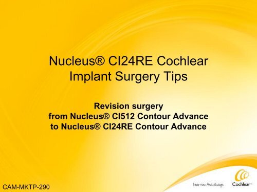
CAM-MKTP-290<br />
Nucleus® CI24RE Cochlear<br />
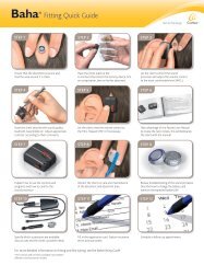
Implant <strong>Surgery</strong> Tips<br />
<strong>Revision</strong> surgery<br />
from Nucleus® <strong>CI512</strong> Con<strong>to</strong>ur Advance<br />
<strong>to</strong> Nucleus® CI24RE Con<strong>to</strong>ur Advance
Nucleus® <strong>CI512</strong> <strong>to</strong> Nucleus CI24RE revision<br />
This presentation reviews key surgical steps<br />
This document is supplemental information – refer <strong>to</strong><br />
Nucleus ® CI24RE Con<strong>to</strong>ur Advance Surgeons Guide for<br />
complete information regarding implantation of the CI24RE<br />
Cochlear Implant<br />
Note: Every implant includes a copy of the Surgeons Guide<br />
as part of the document pack<br />
Ensure the following is available in OR prior <strong>to</strong> starting:<br />
• Primary and backup CI24RE device<br />
• Explant kit
Purpose of this supplemental information<br />
Primary goal of procedure is <strong>to</strong> describe surgical steps <strong>to</strong><br />
replace a Nucleus 5 Cochlear Implant (<strong>CI512</strong>) <strong>to</strong> a Nucleus<br />
CI24RE Cochlear Implant<br />
Note: If there are any questions regarding the steps provided<br />
in this document contact Steve Hazard – Surgical Support<br />
Manager <strong>to</strong> discuss further<br />
Mobile # 1-661-803-4745
Caution<br />
Monopolar Electrocautery cannot be used when a patient has<br />
a cochlear implant or any portion of an electrode lead/ground<br />
lead present – whether the implant is functioning or not<br />
Bipolar Electrocautery is acceptable as long as it remains a<br />
minimum of 1 cm away from any electrode lead or ground<br />
lead and does not <strong>to</strong>uch the receiver package
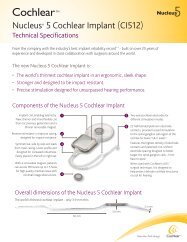
Primary physical differences: CI24RE and <strong>CI512</strong><br />
3.3mm<br />
3.6mm<br />
Nucleus CI24RE<br />
16 mm x 2.3 mm<br />
Nucleus <strong>CI512</strong><br />
3.9 mm<br />
4.6 mm<br />
1. CI24RE has a vertical lead and<br />
ground electrode exiting the<br />
receiver stimula<strong>to</strong>r package.<br />
• Recess this in electrode<br />
channel<br />
2. CI24RE has a pedestal<br />
• Recess the pedestal in bone<br />
2.3mm<br />
Note: With these differences the<br />
CI24RE should be placed slightly<br />
further away from the pinna <strong>to</strong><br />
avoid pressure between the<br />
electrode lead exit and the external<br />
sound processor.
Important point – No overlap<br />
As with all CI surgery<br />
It is important <strong>to</strong> mark<br />
out device location and<br />
ensure there is no<br />
overlap between the<br />
BTE processor and the<br />
internal device
Exposing receiver package<br />
Widen fibrous tissue pocket adjacent <strong>to</strong> coil <strong>to</strong> assist in<br />
“releasing” receiver package<br />
Exiting Lead
Removing receiver package<br />
Cut the electrode lead at a distal location leaving<br />
approximately 1 cm outside the facial recess – then remove<br />
the receiver package, most of the electrode lead and also<br />
remove the ground lead/pin
Clear fibrous tissue & line up recess instrument<br />
1. Clear fibrous tissue from the recessed seat and electrode<br />
channel. Note: The channel may require widening due <strong>to</strong> bone<br />
growth<br />
2. Use Bone Recess Template (Z60479) or Recess Check Gauge<br />
(Z60480) and place circular portion approximately 5mm behind<br />
the lead exit location<br />
5mm<br />
Figure 1. Bone Recess Template<br />
Caution: Always consider the<br />
possibility of exposed dura in<br />
the recessed seat or electrode<br />
lead/ground lead channel –<br />
proceed with care.
Mark location of recess for pedestal<br />
3. Mark location then drill recess including the electrode<br />
lead/ground lead exit in<strong>to</strong> the channel flush with the recess<br />
(Figure 3). Note: The electrode lead/ground lead channel<br />
may require widening due <strong>to</strong> bone growth<br />
Figure 2. Site for recess drawn Figure 3. Site for recess drilled including<br />
lowering of the electrode lead/ground<br />
lead exit <strong>to</strong> be flush with the recess
Create tie-down holes<br />
5. Drill (or reuse) tie-down holes adjacent <strong>to</strong> the new recess seat<br />
per Nucleus CI24RE Surgeons Guide. Use a non-absorbable<br />
synthetic suture <strong>to</strong> secure the receiver package <strong>to</strong> bone
Verify final recess dimensions<br />
4. Use the Recess Check Gauge (Z60480) <strong>to</strong> verify final<br />
dimensions including the electrode lead/ground lead exit<br />
being flush with the bot<strong>to</strong>m of the new recess seat for the<br />
CI24RE receiver package<br />
Figure 4. Verify dimensions using<br />
Recess Check Gauge<br />
NOTE: Failure <strong>to</strong> have the lead<br />
exit flush with the bot<strong>to</strong>m of<br />
the recess will force the exiting<br />
electrode lead/ground lead <strong>to</strong><br />
be deflected upward <strong>to</strong>ward<br />
the soft tissue.
Bony overhangs<br />
6. Verify there are bony overhangs in the mas<strong>to</strong>id cavity <strong>to</strong> retain<br />
excess electrode lead once coiled in<strong>to</strong> position (Figure 5)<br />
Figure 5. Verify bony overhangs are sufficient<br />
in mas<strong>to</strong>id cavity<br />
Bony Overhangs
Place device<br />
7. Place CI24RE receiver package in position and tie-down<br />
(Figure 6 and 7). Ensure knots are <strong>to</strong> the side of the receiver<br />
package.<br />
Figure 6. Freedom Receiver Package<br />
sutured in place<br />
Figure 7. Picture demonstrates a tiedown<br />
technique on an initial cochlear<br />
implant procedure, where a tight<br />
pocket could not be maintained
Electrode Array Removal and<br />
Replacement Considerations<br />
Con<strong>to</strong>ur Advance Electrode
Array considerations<br />
8. Considerations prior <strong>to</strong> removal and replacement of CA array:<br />
• Goal is <strong>to</strong> end up with same depth of insertion<br />
• Be observant of any dura exposure or facial nerve exposure<br />
• Leave old array in position until ready <strong>to</strong> insert new array<br />
• Allow array <strong>to</strong> serve as a stent until ready <strong>to</strong> replace<br />
• Use old cochleos<strong>to</strong>my site (if previously successful)<br />
• Clear away all fibrous tissue from around array at the<br />
cochleos<strong>to</strong>my site – including exposing Silastic Ribs<br />
• No delay between removal and replacement of electrode array –<br />
the “no blink” rule applies – primary concern is the potential for<br />
the fibrous tissue/tunnel <strong>to</strong> collapse once the old array is removed<br />
• Do not perform AOS insertion technique in any revision
Fibrous tissue considerations<br />
Note the fibrous tissue<br />
as electrode array<br />
enters the facial<br />
recess<br />
Caution: If in the<br />
previous surgery any<br />
facial nerve was<br />
exposed then fibrosis<br />
could be attached <strong>to</strong> it<br />
It is recommended <strong>to</strong><br />
assume that facial<br />
nerve is exposed
Silastic “ribs” or rings should be visible<br />
All fibrous tissue is<br />
dissected away at<br />
cochleos<strong>to</strong>my site<br />
Some surgeons<br />
use a laser<br />
Verify that Silastic<br />
“ribs” or rings are<br />
visible<br />
Silastic “rib”<br />
or ring
Preparation for new array insertion<br />
Prepare <strong>to</strong> go in<br />
with new array –<br />
loaded on AOS<br />
Insertion <strong>For</strong>ceps<br />
ready <strong>to</strong> insert<br />
New Array<br />
Old Array
Important reminder<br />
Do not take eyes off of the cochleos<strong>to</strong>my site during the<br />
transition from old array <strong>to</strong> new array. “No Blink” rule<br />
applies<br />
Transition within seconds<br />
If there is <strong>to</strong> be any delay place the tip of the array in<strong>to</strong><br />
the cochleos<strong>to</strong>my site 5 – 6 mm (<strong>to</strong> retain fibrous tunnel<br />
opening intact)
New array insertion / old array removal sequence 1<br />
View 1 of 7: Old array beginning <strong>to</strong> come out<br />
Verify that Silastic “ribs” exit cochleos<strong>to</strong>my site<br />
Silastic “ribs” coming out<br />
1 See the following seven slides (beginning with the current slide)
New array insertion / old array removal sequence<br />
View 2 of 7: Continue removing old array<br />
Silastic “Ribs” continuing<br />
<strong>to</strong> come out
New array insertion / old array removal sequence<br />
View 3 of 7: Old array out – note cochleos<strong>to</strong>my site – enter<br />
immediately with new array in<strong>to</strong> lumen<br />
New Array Old Array (out<br />
of cochlea)
New array insertion / old array removal sequence<br />
View 4 of 7: New array entering cochleos<strong>to</strong>my<br />
Do not perform AOS (Advance Off Stylet)
New array insertion / old array removal sequence<br />
View 5 of 7: Continue insertion – stylet left in place<br />
Do not perform AOS – Advance off-stylet)
New array insertion / old array removal sequence<br />
View 6 of 7: Almost fully inserted
New array insertion / old array removal sequence<br />
View 7 of 7: Fully inserted array – stabilize array and remove<br />
stylet completely
What If Array “Hangs Up”<br />
If insertion is less than 2/3rds complete<br />
• Back array out approximately 2mm<br />
• Rotate 90 degrees <strong>to</strong>ward floor of cochlea<br />
• Attempt <strong>to</strong> advance (if does not advance, rotate 180 degrees<br />
<strong>to</strong>ward osseous spiral lamina – then attempt <strong>to</strong> advance)<br />
If insertion is greater than 2/3 complete (3 – 4 electrodes<br />
outside cochleos<strong>to</strong>my)<br />
• Rotate array in<strong>to</strong> correct orientation then<br />
• Back up array approximately 2 mm – carefully and firmly hold<br />
array and pull stylet 1-2 mm. This allows the distal tip <strong>to</strong><br />
angle <strong>to</strong>ward modiolus (attempting <strong>to</strong> allow array <strong>to</strong> advance<br />
in new direction – and past any lateral wall fibrosis)<br />
• Advance array further if possible
Closure Preparation<br />
Place ground lead ball under temporalis/periosteum<br />
“Seal” cochleos<strong>to</strong>my site<br />
Coil excess lead in mas<strong>to</strong>id cavity and close
Closure
Plain Film Transorbital X-Ray<br />
Not required – at surgeon’s discretion