Impact of Burn-In on Power Supply Reliability - Power Electronics
Impact of Burn-In on Power Supply Reliability - Power Electronics
Impact of Burn-In on Power Supply Reliability - Power Electronics

Create successful ePaper yourself
Turn your PDF publications into a flip-book with our unique Google optimized e-Paper software.
<str<strong>on</strong>g>Impact</str<strong>on</strong>g> <str<strong>on</strong>g>of</str<strong>on</strong>g> <str<strong>on</strong>g>Burn</str<strong>on</strong>g>-<str<strong>on</strong>g>In</str<strong>on</strong>g> <strong>on</strong><br />
<strong>Power</strong> <strong>Supply</strong> <strong>Reliability</strong><br />
Through proper testing and analysis <str<strong>on</strong>g>of</str<strong>on</strong>g> the<br />
accumulated data, power supply manufacturers<br />
can select the appropriate level <str<strong>on</strong>g>of</str<strong>on</strong>g> burn-in to<br />
drive high fi eld reliability while achieving cost<br />
goals.<br />
Users <str<strong>on</strong>g>of</str<strong>on</strong>g> power supply products demand<br />
increasingly higher levels <str<strong>on</strong>g>of</str<strong>on</strong>g> reliability and<br />
performance. Although the suppliers <str<strong>on</strong>g>of</str<strong>on</strong>g><br />
individual comp<strong>on</strong>ents can c<strong>on</strong>fidently<br />
provide impressive life and reliability<br />
data, the compound effect <strong>on</strong> overall reliability can be<br />
signifi cant when a large number <str<strong>on</strong>g>of</str<strong>on</strong>g> individual comp<strong>on</strong>ents<br />
are combined in a module such as a power supply. Perhaps<br />
more important in terms <str<strong>on</strong>g>of</str<strong>on</strong>g> product reliability is the quality<br />
and repeatability <str<strong>on</strong>g>of</str<strong>on</strong>g> the assembly process. Solder joints,<br />
c<strong>on</strong>nectors and mechanical fi xings are all potential origins<br />
for product failure. <str<strong>on</strong>g>In</str<strong>on</strong>g> use, operating temperature and other<br />
envir<strong>on</strong>mental factors also affect the l<strong>on</strong>gevity and reliability<br />
<str<strong>on</strong>g>of</str<strong>on</strong>g> a power supply.<br />
<str<strong>on</strong>g>Burn</str<strong>on</strong>g>-in and various other forms <str<strong>on</strong>g>of</str<strong>on</strong>g> life and stress testing<br />
help provide the data to enable power supply manufacturers<br />
to c<strong>on</strong>tinually improve the reliability <str<strong>on</strong>g>of</str<strong>on</strong>g> their products.<br />
<str<strong>on</strong>g>In</str<strong>on</strong>g>deed, when analyzed correctly and fed back into the design<br />
and assembly process, the accumulated data can be used to<br />
optimize the test and burn-in process.<br />
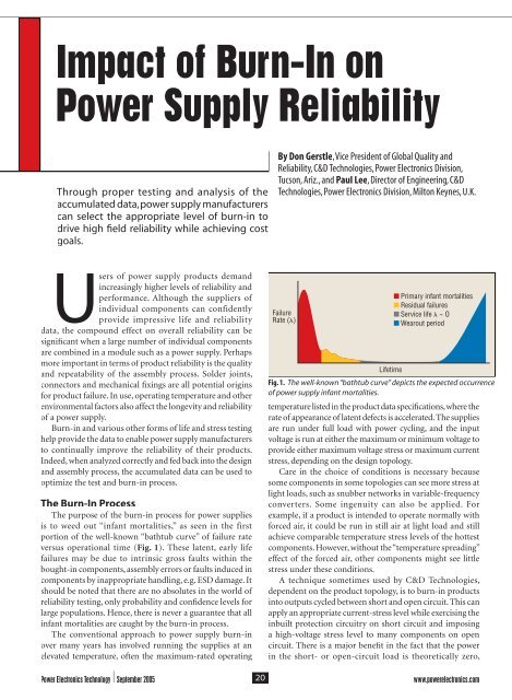
The <str<strong>on</strong>g>Burn</str<strong>on</strong>g>-<str<strong>on</strong>g>In</str<strong>on</strong>g> Process<br />
The purpose <str<strong>on</strong>g>of</str<strong>on</strong>g> the burn-in process for power supplies<br />
is to weed out “infant mortalities,” as seen in the first<br />
porti<strong>on</strong> <str<strong>on</strong>g>of</str<strong>on</strong>g> the well-known “bathtub curve” <str<strong>on</strong>g>of</str<strong>on</strong>g> failure rate<br />
versus operati<strong>on</strong>al time (Fig. 1). These latent, early life<br />
failures may be due to intrinsic gross faults within the<br />
bought-in comp<strong>on</strong>ents, assembly errors or faults induced in<br />
comp<strong>on</strong>ents by inappropriate handling, e.g. ESD damage. It<br />
should be noted that there are no absolutes in the world <str<strong>on</strong>g>of</str<strong>on</strong>g><br />
reliability testing, <strong>on</strong>ly probability and c<strong>on</strong>fi dence levels for<br />
large populati<strong>on</strong>s. Hence, there is never a guarantee that all<br />
infant mortalities are caught by the burn-in process.<br />
The c<strong>on</strong>venti<strong>on</strong>al approach to power supply burn-in<br />
over many years has involved running the supplies at an<br />
elevated temperature, <str<strong>on</strong>g>of</str<strong>on</strong>g>ten the maximum-rated operating<br />
By D<strong>on</strong> Gerstle, Vice President <str<strong>on</strong>g>of</str<strong>on</strong>g> Global Quality and<br />
<strong>Reliability</strong>, C&D Technologies, <strong>Power</strong> Electr<strong>on</strong>ics Divisi<strong>on</strong>,<br />
Tucs<strong>on</strong>, Ariz., and Paul Lee, Director <str<strong>on</strong>g>of</str<strong>on</strong>g> Engineering, C&D<br />
Technologies, <strong>Power</strong> Electr<strong>on</strong>ics Divisi<strong>on</strong>, Milt<strong>on</strong> Keynes, U.K.<br />
Failure<br />
Rate ()<br />
Lifetime<br />
Primary infant mortalities<br />
Residual failures<br />
Service life ~ O<br />
Wearout period<br />
Fig. 1. The well-known “bathtub curve” depicts the expected occurrence<br />
<str<strong>on</strong>g>of</str<strong>on</strong>g> power supply infant mortalities.<br />
temperature listed in the product data specifi cati<strong>on</strong>s, where the<br />
rate <str<strong>on</strong>g>of</str<strong>on</strong>g> appearance <str<strong>on</strong>g>of</str<strong>on</strong>g> latent defects is accelerated. The supplies<br />
are run under full load with power cycling, and the input<br />
voltage is run at either the maximum or minimum voltage to<br />
provide either maximum voltage stress or maximum current<br />
stress, depending <strong>on</strong> the design topology.<br />
Care in the choice <str<strong>on</strong>g>of</str<strong>on</strong>g> c<strong>on</strong>diti<strong>on</strong>s is necessary because<br />
some comp<strong>on</strong>ents in some topologies can see more stress at<br />
light loads, such as snubber networks in variable-frequency<br />
c<strong>on</strong>verters. Some ingenuity can also be applied. For<br />
example, if a product is intended to operate normally with<br />
forced air, it could be run in still air at light load and still<br />
achieve comparable temperature stress levels <str<strong>on</strong>g>of</str<strong>on</strong>g> the hottest<br />
comp<strong>on</strong>ents. However, without the “temperature spreading”<br />
effect <str<strong>on</strong>g>of</str<strong>on</strong>g> the forced air, other comp<strong>on</strong>ents might see little<br />
stress under these c<strong>on</strong>diti<strong>on</strong>s.<br />
A technique sometimes used by C&D Technologies,<br />
dependent <strong>on</strong> the product topology, is to burn-in products<br />
into outputs cycled between short and open circuit. This can<br />
apply an appropriate current-stress level while exercising the<br />
inbuilt protecti<strong>on</strong> circuitry <strong>on</strong> short circuit and imposing<br />
a high-voltage stress level to many comp<strong>on</strong>ents <strong>on</strong> open<br />
circuit. There is a major benefi t in the fact that the power<br />
in the short- or open-circuit load is theoretically zero,<br />
<strong>Power</strong> Electr<strong>on</strong>ics Technology September 2005 20<br />
www.powerelectr<strong>on</strong>ics.com
Failure<br />
Rate ()<br />
POWER SUPPLY RELIABILITY<br />
Lifetime<br />
Primary infant mortalities<br />
Residual failures<br />
Service life ~ O<br />
High Temp/Min<br />
Low Temp/Min<br />
Fig. 2. An increasing thermal rate <str<strong>on</strong>g>of</str<strong>on</strong>g> change in power supply testing<br />
produces an increased rate <str<strong>on</strong>g>of</str<strong>on</strong>g> failure and earlier failures.<br />
although practically the short might be a MOSFET, turned<br />
<strong>on</strong>, dissipating a few watts.<br />
This method alleviates the real problem <str<strong>on</strong>g>of</str<strong>on</strong>g> energy waste<br />
in burn-in loads. However, some types <str<strong>on</strong>g>of</str<strong>on</strong>g> comp<strong>on</strong>ent stresses<br />
are not applied with this method because the overall power<br />
supplied by the unit is low, and therefore self-heating may<br />
be low. An elevated ambient temperature will compensate<br />
for this in part, perhaps using the waste heat from the burnin<br />
loads. As menti<strong>on</strong>ed, some product topologies are not<br />
suitable for this burn-in method, such as those that have a<br />
poorly defi ned or str<strong>on</strong>gly re-entrant short-circuit current<br />
characteristic. That is, if <strong>on</strong> a “hard” short circuit the output<br />
current reduces to much less than the rated maximum<br />
output current, the level <str<strong>on</strong>g>of</str<strong>on</strong>g> burn-in stress may be too low to<br />
be effective. The decisi<strong>on</strong> <strong>on</strong> burn-in c<strong>on</strong>fi gurati<strong>on</strong> is made<br />
jointly between the design and reliability/quality engineers<br />
to ensure optimized screening.<br />
Data logging and analysis <str<strong>on</strong>g>of</str<strong>on</strong>g> the units under test is<br />
important for determining whether a failure has occurred,<br />
and if so, when. If all failures occur in the fi rst few minutes<br />
<str<strong>on</strong>g>of</str<strong>on</strong>g> a 48-hr burn-in sequence, there would be good reas<strong>on</strong><br />
to shorten the time and increase throughput while saving<br />
energy. C&D Technologies tests products comprehensively<br />
before and after burn-in to ensure that any changes in<br />
performance are identifi ed. This also can show whether there<br />
are any intermittent problems. Understanding and using<br />
burn-in data to modify product design and manufacturing<br />
processes can result in improved reliability and yield. C&D<br />
Technologies uses its burn-in data to drive the c<strong>on</strong>tinuous<br />
improvement quality process.<br />
Experience in burn-in testing has shown that thermal<br />
cycling precipitates more infant mortalities than a c<strong>on</strong>stant<br />
elevated ambient, although the sets <str<strong>on</strong>g>of</str<strong>on</strong>g> failures d<strong>on</strong>’t<br />
completely overlap. Thermal cycling with a dwell time at each<br />
thermal extreme is therefore the preferred process. <str<strong>on</strong>g>In</str<strong>on</strong>g>creasing<br />
the thermal rate <str<strong>on</strong>g>of</str<strong>on</strong>g> change precipitates more failures in fewer<br />
cycles as illustrated in Fig. 2.<br />
Note that with increased thermal rate, different<br />
populati<strong>on</strong>s <str<strong>on</strong>g>of</str<strong>on</strong>g> failures can appear that are more or less<br />
affected by this type <str<strong>on</strong>g>of</str<strong>on</strong>g> stress and the occurrence <str<strong>on</strong>g>of</str<strong>on</strong>g> some<br />
residual failure types is unaffected. Even though there is<br />
equipment available to achieve thermal rates <str<strong>on</strong>g>of</str<strong>on</strong>g> change <str<strong>on</strong>g>of</str<strong>on</strong>g> up<br />
to 60°C per minute, some manufacturers d<strong>on</strong>’t exceed 40°C<br />
<br />
<br />
<br />
<br />
<br />
<br />
<br />
<br />
Booth 909<br />
CIRCLE 213 <strong>on</strong> Reader Service Card or freeproductinfo.net/pet<br />
www.powerelectr<strong>on</strong>ics.com 21<br />
<strong>Power</strong> Electr<strong>on</strong>ics Technology September 2005
POWER SUPPLY RELIABILITY<br />
per minute to prevent excessive thermal stress that may cause<br />
cracking <str<strong>on</strong>g>of</str<strong>on</strong>g> multilayer ceramic capacitors (MLCCs).<br />
<str<strong>on</strong>g>In</str<strong>on</strong>g> the absence <str<strong>on</strong>g>of</str<strong>on</strong>g> thermal cycling chambers, power cycling<br />
at an elevated ambient with judiciously selected cycle times<br />
approaches the effectiveness <str<strong>on</strong>g>of</str<strong>on</strong>g> the thermal cycling/dwell<br />
process. Care must be taken to ensure that the products are<br />
not stressed outside <str<strong>on</strong>g>of</str<strong>on</strong>g> their ratings in the <str<strong>on</strong>g>of</str<strong>on</strong>g>ten-atypical<br />
envir<strong>on</strong>ment <str<strong>on</strong>g>of</str<strong>on</strong>g> burn-in. If overstressed, some useful life<br />
<str<strong>on</strong>g>of</str<strong>on</strong>g> a good product could be used up, and at worst, hard or<br />
latent failures could actually be induced in otherwise good<br />
product.<br />
At C&D Technologies, the burn-in process normally<br />
starts with a durati<strong>on</strong> <str<strong>on</strong>g>of</str<strong>on</strong>g> 48 hr, with a decisi<strong>on</strong> process to<br />
reduce the time <str<strong>on</strong>g>of</str<strong>on</strong>g> burn-in when no failures occur after a set<br />
number <str<strong>on</strong>g>of</str<strong>on</strong>g> hours. Depending <strong>on</strong> the product’s complexity<br />
and topology, a decisi<strong>on</strong> is made to reduce the future burn-in<br />
hours by half after 200 to 500 units have g<strong>on</strong>e through the<br />
process with no failures occurring in a quarter <str<strong>on</strong>g>of</str<strong>on</strong>g> the current<br />
burn-in time. This process is c<strong>on</strong>tinued until the burn-in<br />
time is reduced to 2 hr, where it is held for the remainder<br />
<str<strong>on</strong>g>of</str<strong>on</strong>g> producti<strong>on</strong>.<br />
Some c<strong>on</strong>tend that burn-in can be eliminated when no<br />
failures occur after multiple producti<strong>on</strong> builds. However, it<br />
could be argued that this removes the insurance against a<br />
group 96817.4p1c.Switcher <str<strong>on</strong>g>of</str<strong>on</strong>g> defective comp<strong>on</strong>ents Mag_C&K being 1/12/05 used 9:12 and/or AM a Page process 1<br />
anomaly occurring. <str<strong>on</strong>g>In</str<strong>on</strong>g> volume producti<strong>on</strong> <str<strong>on</strong>g>of</str<strong>on</strong>g> parts that are<br />
From 1 Watt to<br />
200 Watts<br />
Transformers<br />
<str<strong>on</strong>g>In</str<strong>on</strong>g>ductors<br />
Filters<br />
EMI/RFI CMCs<br />
For UL/CSA recognized magnetic<br />
comp<strong>on</strong>ents...for SMPS<br />
applicati<strong>on</strong>s...designed for use<br />
with leading semic<strong>on</strong>ductors...for<br />
applicati<strong>on</strong> notes and reference<br />
circuits...call Premier, the<br />
"<str<strong>on</strong>g>In</str<strong>on</strong>g>novators in Magnetics Technology".<br />
20381 Barents Sea Circle<br />
Lake Forest, CA 92630 Tel. (949) 452-0511<br />
www.premiermag.com<br />
CIRCLE 214 <strong>on</strong> Reader Service Card or freeproductinfo.net/pet<br />
known to have a signifi cant infant mortality rate—perhaps<br />
because <str<strong>on</strong>g>of</str<strong>on</strong>g> the degree <str<strong>on</strong>g>of</str<strong>on</strong>g> manual assembly—a regime <str<strong>on</strong>g>of</str<strong>on</strong>g><br />
variable burn-in can be used whereby failures are expected.<br />
However, when a precalculated period <str<strong>on</strong>g>of</str<strong>on</strong>g> failure-free<br />
operati<strong>on</strong> <str<strong>on</strong>g>of</str<strong>on</strong>g> a batch has elapsed, burn-in is terminated. This<br />
period is found from statistical tables, given the expected<br />
percentage <str<strong>on</strong>g>of</str<strong>on</strong>g> infant mortalities, their known failure rate<br />
and distributi<strong>on</strong> type, batch size and percentage c<strong>on</strong>fi dence<br />
level required that <strong>on</strong>ly a given number <str<strong>on</strong>g>of</str<strong>on</strong>g> latent failures<br />
remain.<br />
For example, c<strong>on</strong>sider a batch <str<strong>on</strong>g>of</str<strong>on</strong>g> 10,000 units that<br />
historically has had 10 infant mortalities per batch <str<strong>on</strong>g>of</str<strong>on</strong>g> a<br />
type found to have a mean time to failure (MTTF) <str<strong>on</strong>g>of</str<strong>on</strong>g> 10<br />
hr at the burn-in temperature. <str<strong>on</strong>g>In</str<strong>on</strong>g> this case, tables in the<br />
book Electr<strong>on</strong>ic Comp<strong>on</strong>ent <strong>Reliability</strong>: Fundamentals,<br />
Modelling, Evaluati<strong>on</strong>, and Assurance [1] by Finn Jensen<br />
show that a failure-free period <str<strong>on</strong>g>of</str<strong>on</strong>g> 13 hr must pass to give a<br />
90% c<strong>on</strong>fi dence level that <strong>on</strong>ly <strong>on</strong>e latent product failure<br />
remains. The period extends to 24 hr to have the same<br />
c<strong>on</strong>fi dence level that no latent infant mortality-type failures<br />
remain.<br />
Some manufacturers have taken the burn-in process<br />
further after fi nding that the types <str<strong>on</strong>g>of</str<strong>on</strong>g> burn-in described do<br />
not eliminate, within a reas<strong>on</strong>able time, all <str<strong>on</strong>g>of</str<strong>on</strong>g> the failures<br />
seen to occur in the early life <str<strong>on</strong>g>of</str<strong>on</strong>g> a power supply. Also,<br />
c<strong>on</strong>venti<strong>on</strong>al burn-in does not provoke early failures that<br />
could be a result <str<strong>on</strong>g>of</str<strong>on</strong>g> the shock and vibrati<strong>on</strong> <str<strong>on</strong>g>of</str<strong>on</strong>g> shipping<br />
and handling. To combat this, a more aggressive highly<br />
accelerated stress screen (HASS) can be used that applies<br />
mechanical, thermal and electrical stress typically bey<strong>on</strong>d<br />
product ratings but within design margins. Accelerati<strong>on</strong><br />
factors <str<strong>on</strong>g>of</str<strong>on</strong>g> more than 40 over c<strong>on</strong>venti<strong>on</strong>al burn-in have been<br />
claimed for this method, giving corresp<strong>on</strong>dingly shorter<br />
test times. A problem however is that the stress levels are so<br />
extreme there is a risk <str<strong>on</strong>g>of</str<strong>on</strong>g> damaging good product with hard<br />
or latent failures.<br />
<str<strong>on</strong>g>In</str<strong>on</strong>g> answer to this, the highly accelerated life test (HALT)<br />
process was designed to identify the real damage limits in a<br />
product by stressing the product to failure with temperature<br />
extremes, thermal cycling, progressively higher levels <str<strong>on</strong>g>of</str<strong>on</strong>g><br />
vibrati<strong>on</strong>, and then a combinati<strong>on</strong> <str<strong>on</strong>g>of</str<strong>on</strong>g> thermal cycling and<br />
vibrati<strong>on</strong>. During this testing, the destructi<strong>on</strong> limits <str<strong>on</strong>g>of</str<strong>on</strong>g> the<br />
power supply are identifi ed. These operating limits are then<br />
used to set the less-severe HASS test levels.<br />
HALT also is used extensively during product development<br />
to identify potential weaknesses in the design. The test<br />
equipment required to do HALT must typically ramp<br />
temperature between -55°C to 125°C while applying six-axis<br />
linear and rotati<strong>on</strong>al random vibrati<strong>on</strong>. This requires a major<br />
capital investment and is <str<strong>on</strong>g>of</str<strong>on</strong>g>ten subc<strong>on</strong>tracted to specialist<br />
test houses. Some vendors such as C&D Technologies already<br />
have internal HALT facilities.<br />
The No <str<strong>on</strong>g>Burn</str<strong>on</strong>g>-<str<strong>on</strong>g>In</str<strong>on</strong>g> Model<br />
As described earlier in the article, <strong>on</strong>ce burn-in failures<br />
have reduced to a certain level, some manufacturers<br />
<strong>Power</strong> Electr<strong>on</strong>ics Technology September 2005 22<br />
www.powerelectr<strong>on</strong>ics.com
POWER SUPPLY RELIABILITY<br />
feel that the process can be dropped<br />
completely. This can be c<strong>on</strong>sidered<br />
<strong>on</strong>ly if the manufacturing process is<br />
entirely predictable and the quality <str<strong>on</strong>g>of</str<strong>on</strong>g><br />
bought-in material is such that it has<br />
no gross latent intrinsic defects. <str<strong>on</strong>g>In</str<strong>on</strong>g><br />
other words, the bought-in comp<strong>on</strong>ents<br />
themselves d<strong>on</strong>’t exhibit significant<br />
infant mortalities and <strong>on</strong>ly have their<br />
intrinsic low-level latent defect rate.<br />
Although commodity comp<strong>on</strong>ents<br />
approach this quality level and modern<br />
manufacturing quality c<strong>on</strong>trol can<br />
minimize process variati<strong>on</strong>s, there is<br />
still a real risk that a customer may see<br />
some early life failures. The cost <str<strong>on</strong>g>of</str<strong>on</strong>g> this<br />
in terms <str<strong>on</strong>g>of</str<strong>on</strong>g> goodwill has to be weighed<br />
against the cost <str<strong>on</strong>g>of</str<strong>on</strong>g> burn-in. Remember<br />
that customers will still see the intrinsic<br />
failure rate <str<strong>on</strong>g>of</str<strong>on</strong>g> the product in its service<br />
life. A small extra number <str<strong>on</strong>g>of</str<strong>on</strong>g> failures<br />
attributable to infant mortalities may<br />
CIRCLE 216 <strong>on</strong> Reader Service Card or freeproductinfo.net/pet<br />
not be signifi cant. For example, <strong>on</strong>e<br />
product from C&D Technologies that<br />
uses quality comp<strong>on</strong>ents is built using<br />
a stable, mature process without burnin<br />
and has an observed fi eld mean time<br />
between failure (MTBF) <str<strong>on</strong>g>of</str<strong>on</strong>g> more than<br />
25 milli<strong>on</strong> hr. This fi gure is derived from<br />
130 failures in the total sales <str<strong>on</strong>g>of</str<strong>on</strong>g> 4.37<br />
milli<strong>on</strong> parts shipped evenly over six<br />
years. <str<strong>on</strong>g>In</str<strong>on</strong>g> this case, it is assumed that the<br />
parts are powered for 25% <str<strong>on</strong>g>of</str<strong>on</strong>g> any given<br />
period and that <strong>on</strong>ly 10% <str<strong>on</strong>g>of</str<strong>on</strong>g> failures are<br />
actually reported.<br />
While extended burn-in tests may<br />
be employed <strong>on</strong> small numbers <str<strong>on</strong>g>of</str<strong>on</strong>g> units<br />
to gage whether all infant mortality<br />
failures have been identifi ed, at C&D<br />
Technologies, <strong>on</strong>going life tests are run<br />
for up to six m<strong>on</strong>ths <strong>on</strong> 25 to 50 units<br />
at a moderately elevated temperature.<br />
These tests are normally <strong>on</strong>ly used when<br />
there are large quantities <str<strong>on</strong>g>of</str<strong>on</strong>g> units built<br />
<strong>on</strong> a c<strong>on</strong>tinuing basis and can give an<br />
estimate <str<strong>on</strong>g>of</str<strong>on</strong>g> the intrinsic reliability <str<strong>on</strong>g>of</str<strong>on</strong>g> a<br />
product in service, that is, MTBF.<br />
The accuracy <str<strong>on</strong>g>of</str<strong>on</strong>g> this fi gure depends<br />
<strong>on</strong> the relatively mild failure-rate<br />
accelerati<strong>on</strong> during the test having<br />
a known relati<strong>on</strong>ship to the real-life<br />
failure rate. The Arrhenius equati<strong>on</strong><br />
can give a value for the accelerati<strong>on</strong><br />
factor given a c<strong>on</strong>stant failure rate<br />
after infant mortalities. The Arrhenius<br />
equati<strong>on</strong> has its origins in chemistry.<br />
So in theory, it requires a knowledge<br />
<str<strong>on</strong>g>of</str<strong>on</strong>g> effective “activati<strong>on</strong> energies” for all<br />
failure modes. But in practice, the rule<br />
<str<strong>on</strong>g>of</str<strong>on</strong>g> thumb is to double the accelerati<strong>on</strong><br />
factor for each 10°C rise above the reallife<br />
operating temperature.<br />
As an example, 50 units running for<br />
six m<strong>on</strong>ths at 70°C with no failures gives<br />
219,000 operati<strong>on</strong>al hr. From statistical<br />
tables, this represents a failure rate <str<strong>on</strong>g>of</str<strong>on</strong>g><br />
4110 failures in 10 9 hr <str<strong>on</strong>g>of</str<strong>on</strong>g> operati<strong>on</strong><br />
(FITs) with a 60% c<strong>on</strong>fi dence level or<br />
10,502 FITs with 90% c<strong>on</strong>fi dence. At a<br />
lower temperature <str<strong>on</strong>g>of</str<strong>on</strong>g> say 40°C, our rule<br />
<str<strong>on</strong>g>of</str<strong>on</strong>g> thumb for an accelerati<strong>on</strong> factor to<br />
70°C is eight, so the fi gures reduce to<br />
514 FITs and 1313 FITs.<br />
FIT is λ x 10 9 , and MTBF is 1/λ, so<br />
these fi gures represent 1.95 milli<strong>on</strong> hr<br />
or 760,000 hr MTBF at 60% and 90%<br />
c<strong>on</strong>fi dence levels, respectively. It may<br />
seem odd that a test with no failures<br />
<strong>Power</strong> Electr<strong>on</strong>ics Technology September 2005 24<br />
www.powerelectr<strong>on</strong>ics.com
gives a fi nite failure rate. This is because<br />
it is assumed that the fi rst failure is<br />
just about to happen. It should be<br />
emphasized that real fi eld failure rate<br />
is the most accurate measure <str<strong>on</strong>g>of</str<strong>on</strong>g> the<br />
reliability <str<strong>on</strong>g>of</str<strong>on</strong>g> a product.<br />
A calculated MTBF can be compared<br />
with the dem<strong>on</strong>strated fi gure obtained<br />
through life testing to check for<br />
c<strong>on</strong>sistency. However, the calculati<strong>on</strong>s<br />
can be misleading depending <strong>on</strong> the<br />
base failure rates used for comp<strong>on</strong>ents<br />
and the method <str<strong>on</strong>g>of</str<strong>on</strong>g> calculati<strong>on</strong>. A recent<br />
survey by C&D Technologies found a<br />
variati<strong>on</strong> <str<strong>on</strong>g>of</str<strong>on</strong>g> a factor <str<strong>on</strong>g>of</str<strong>on</strong>g> more than 100<br />
between MTBF fi gures for the same<br />
circuit calculated by several different<br />
power supply manufacturers. Different<br />
standards such as MIL-HDBK-217F<br />
and Telcordia SR332 will give different<br />
answers.<br />
<str<strong>on</strong>g>In</str<strong>on</strong>g> additi<strong>on</strong>, the MIL standard also<br />
gives two different methods. One<br />
method is the parts count, which gives<br />
a quick but c<strong>on</strong>servative measure, and<br />
the other is the part stress method,<br />
which requires detailed knowledge<br />
<str<strong>on</strong>g>of</str<strong>on</strong>g> the electrical operating c<strong>on</strong>diti<strong>on</strong>s.<br />
The latter method is more realistic. As<br />
an example <str<strong>on</strong>g>of</str<strong>on</strong>g> a part stress calculati<strong>on</strong><br />
according to MIL-HDBK-217F, a<br />
general-purpose diode has a failure<br />
rate per milli<strong>on</strong> hours given by:<br />
λ P = λ B T S C Q E<br />
where λ B is a base failure rate for<br />
different types <str<strong>on</strong>g>of</str<strong>on</strong>g> diodes and the factors<br />
are for temperature, electrical stress,<br />
internal c<strong>on</strong>structi<strong>on</strong>, manufacturing<br />
quality and envir<strong>on</strong>ment <str<strong>on</strong>g>of</str<strong>on</strong>g> use,<br />
respectively. For a Schottky power diode<br />
operating at a juncti<strong>on</strong> temperature<br />
<str<strong>on</strong>g>of</str<strong>on</strong>g> 80°C, with a voltage stress <str<strong>on</strong>g>of</str<strong>on</strong>g> 75%<br />
<str<strong>on</strong>g>of</str<strong>on</strong>g> its rating, metallurgically b<strong>on</strong>ded<br />
c<strong>on</strong>structi<strong>on</strong>, plastic commercial<br />
packaging and operated in a “ground<br />
benign” envir<strong>on</strong>ment, the calculati<strong>on</strong><br />
is changed by substituti<strong>on</strong>s from the<br />
tables in the standard to become:<br />
λ P = 0.003 x 5 x 0.58 x 1 x 8 x 1 =<br />
0.0696 failures per milli<strong>on</strong> hours, or<br />
69.6 FITs.<br />
Optimizing Process C<strong>on</strong>trol<br />
The important point to note is<br />
that quality and reliability cannot be<br />
“tested in” or “inspected in.” <str<strong>on</strong>g>Burn</str<strong>on</strong>g>-in<br />
testing is ultimately another inspecti<strong>on</strong><br />
process, but serves as a mechanism for<br />
process c<strong>on</strong>trol and feedback. Failures<br />
in burn-in al<strong>on</strong>g with field failures<br />
prompt failure analysis and corrective<br />
acti<strong>on</strong> to ensure that the product<br />
design and process have been centered<br />
and optimized to provide the best<br />
product possible to the fi eld. Studies<br />
have shown that higher factory yields<br />
give higher product reliability, happier<br />
POWER SUPPLY RELIABILITY<br />
customers and lower warranty-return<br />
costs. PETech<br />
References<br />
1. Jensen, Finn. Electr<strong>on</strong>ic Comp<strong>on</strong>ent<br />
<strong>Reliability</strong>: Fundamentals, Modelling,<br />
Evaluati<strong>on</strong>, and Assurance. John<br />
Wiley & S<strong>on</strong>s, 1995. The tables in this<br />
reference are credited to Marcus and<br />
Blumenthal (1974) by permissi<strong>on</strong> <str<strong>on</strong>g>of</str<strong>on</strong>g><br />
the American Statistical Associati<strong>on</strong>.<br />
CIRCLE 217 <strong>on</strong> Reader Service Card or freeproductinfo.net/pet<br />
www.powerelectr<strong>on</strong>ics.com 25<br />
<strong>Power</strong> Electr<strong>on</strong>ics Technology September 2005