Grameen Sampark Final April 0... - pmgsy
Grameen Sampark Final April 0... - pmgsy
Grameen Sampark Final April 0... - pmgsy

You also want an ePaper? Increase the reach of your titles
YUMPU automatically turns print PDFs into web optimized ePapers that Google loves.
In this Issue<br />
Editorial 3<br />
Potential Applications of 4<br />
Interlocking Concrete Block Paving in<br />
Rural Roads Construction<br />
Dr. S.D. Sharma, B.M. Sharma and<br />
Dr. P.K. Nanda<br />
Performance Criteria for 15<br />
Design of Low Volume Rural Roads<br />
U. C. Sahoo, M. Amaranatha Reddy and<br />
K. Sudhakar Reddy<br />
Stabilization of Soil Subgrade 22<br />
with Polypropylene Fibres<br />
Dr. I.K.Pateriya and Dr. K. A. Patil<br />
Experiencing Folded Plates in<br />
Roadworks Retaining Structure<br />
Dipankar Chakrabarti and<br />
Shyamalendu Mukherjee<br />
News in Brief 32<br />
th<br />
The National Rural Roads Development Agency (NRRDA) was established on 14 January, 2002 as<br />
the dedicated agency of the Ministry of Rural Development for the operational management of the<br />
rural roads programme - PMGSY<br />
<strong>Grameen</strong> <strong>Sampark</strong> is a newsletter of the NRRDA containing items of topical interest. For official text<br />
or detailed information please contact NRRDA or visit the website.<br />
Published by: National Rural Roads Development Agency<br />
th<br />
(NRRDA), 5 Floor, 15, NBCC Tower, Bhikaji Cama Place,<br />
New Delhi-110066<br />
e-mail: nrrda@<strong>pmgsy</strong>.nic.in Website:www.<strong>pmgsy</strong>.nic.in<br />
Editing, Design & Printing by Akhil Chandra Associates<br />
N-70/4, South Avenue, Sainik Farm, New Delhi-110062<br />
Ph.: 29553965, Email: akhilchandraassociates@gmail.com<br />
For article contribution and free subscription contact:<br />
Dr. B.P. Chandrasekhar, Director (Tech.), NRRDA,<br />
(email: bpc@alpha.nic.in).<br />
Note: Accepted articles may be condensed.<br />
27
Editorial<br />
Pradhan Mantri Gram Sadak Yojana<br />
We often preach, but rarely practice, the old adage 'a stitch in time saves nine'. This disconnect also largely<br />
pervades our approaches to the management of the huge network of rural roads which we have built up over the<br />
years with considerable investment of tax payers' money. PMGSY sought to practically address this malady by<br />
embedding 'planned 5 year maintenance of completed roads' in the programme guidelines. However, anecdotal<br />
evidence, buttressed by limited field observations of independent monitors, indicates that this policy has not<br />
achieved substantial success in terms of the intended outcome across States. Sample inspection of 4412 roads by the<br />
National Quality Monitors, during December2007and December 2008 reveal that a very high proportion ( 32%)of<br />
PMGSY roads were not being maintained at all, contrary to the stated policy. Since we have already completed<br />
construction of over 2 lakh km. of rural roads under PMGSY, by investing close to US $ 10 billion, quite obviously,<br />
institutionalizing an efficient maintenance management policy cannot brook any further delay.<br />
Efficient management of rural roads requires not only enhancement in budgetary outlay but even more<br />
importantly change in systems, procedures and processes. One thing is quite clear business as usual will not work.<br />
What is called for essentially is a paradigm shift in our approach to maintenance management. It is in this context that<br />
NRRDA is holding a workshop in collaboration with the Government of Andhra Pradesh to explore the feasibility of<br />
applying principles of Asset Management to rural roads. Asset Management seeks to synergize ideas and principles of<br />
Engineering as well as Management Sciences with a view to developing a decision making framework that helps in<br />
choosing the optimal strategy for managing high value infrastructure assets. At its core, asset management is a<br />
business process which strives to maintain a prescribed level of service at the lowest cost possible. Allocation of<br />
resources on the basis of a well-defined set of policy goals and objectives, evaluation of alternative options in terms of<br />
their impact on relevant policy objectives and monitoring results with reference to measurable performance<br />
benchmarks are some of the core principles of Asset Management.<br />
Adoption of Asset Management principles for rural roads would call for major institutional as well as<br />
attitudinal changes. Challenging the status quo is by no means easy; but it is certainly doable. We can ill afford to let<br />
our precious rural road assets to deteriorate by sheer atrophy and the prevailing culture of niggardliness towards<br />
maintenance.<br />
(J.K. Mohapatra)<br />
Director General, NRRDA<br />
Asset Management: Building a culture of<br />
sustainable maintenance of rural roads.<br />
<strong>Grameen</strong> <strong>Sampark</strong><br />
3
4<br />
Potential Applications of<br />
Interlocking Concrete Block Paving in<br />
Rural Roads Construction<br />
Dr. S.D. Sharma*, B.M. Sharma**, Dr. P.K. Nanda***<br />
Transport Infrastructure development in rural areas is<br />
absolutely essential for soci-economic upliftment of<br />
rural population. An adequate road transport system<br />
improves connectivity to the inaccessible areas and in<br />
turn facilitates smooth flow of goods and services. Rural<br />
roads also help the rural population in terms of<br />
increased mobility to schools, health centers, market<br />
centers and create more employment opportunities.<br />
They also provide accessibility to productive resources<br />
and physical mobility of raw materials, farm produce<br />
and other products, promote industrialization, increase<br />
the size of markets and create enhanced economic<br />
prosperity, etc. Economic developments brought about<br />
<strong>Grameen</strong> <strong>Sampark</strong><br />
through increased mobility and accessibility turns into<br />
income-generating skills, increased income for rural<br />
workers, positive changes in socio-economic attitude<br />
and reduction in inequalities between different regions,<br />
leading to increased productivity on the whole.<br />
Provision of roads in rural areas is a gigantic task as<br />
about six lakh villages in India are scattered widely over<br />
a vast area of 33 lakh sq. km.<br />
The Government of India has been making sincere<br />
efforts in this direction and has implemented a number<br />
of rural development programmes since 1974, with<br />
development of rural roads as one of the major<br />
objectives. Prominent amongst these are : Minimum<br />
*Scientist, **Head (Pavement Evaluation Division) and ***Director, Central Road Research Institute, New Delhi<br />
nd th<br />
Reprinted from the proceeding of National Conference on Rural Roads (22 to 24 May 07) New Delhi
Needs Programme, National Rural Employment<br />
Programme, Rural Landless Employment Guarantee<br />
Programme, and Jawahar Rozgar Yojana. However,<br />
these programmes lacked science and technology<br />
contents / inputs and were primarily targeted as drought<br />
relief and employment guarantee as their main<br />
objectives. Due to these reasons, they had limited<br />
success in the overall development of rural roads. The<br />
lack of scientific planning and methods in creating rural<br />
infrastructure and the centralized nature of<br />
implementation proved to be impediments in creating<br />
durable rural roads, through such programmes.<br />
In tune with the objectives of Road Development Plan<br />
Vision (1), a national mission popularly known as<br />
“PMGSY” (Pradhan Mantri Gram Sadak Yojna), for<br />
achieving rural connectivity through provisions of allweather<br />
roads to remote villages was initiated in 2000<br />
by the Government of India, with the overall objective<br />
of connecting all villages having population of more<br />
than 500 by the year 2007. This is an ambitious<br />
programme with far-reaching positive returns and<br />
consequences for the nation's economy, in general, and<br />
the rural economy, in particular. It is expected that,<br />
through the implementation of this programme, out of<br />
the 3,50,000 unconnected habitations, 1,60,000<br />
habitations will be benefited, with construction of some<br />
6,00,000 km of new all-weather roads. This will<br />
constitute an addition of 33 per cent to the existing<br />
18,20,000 km of rural roads and 20 per cent to the<br />
existing network of 33,00,000 km of total roads in the<br />
country. The current estimate of total investments<br />
needed for this stupendous task is Rs.60,000 crores. It is<br />
estimated that the effective implementation of PMGSY<br />
would lead to three times increase in the per capita GDP<br />
(Gross Domestic Product) within one decade. Thus, the<br />
fulfillment of this programme will lead to a quantum<br />
jump in the nation's economy (2,3). Since the local selfgovernments<br />
are actively involved in the planning,<br />
designing and implementation of this programme, there<br />
is scope for people's participation at the grassroots<br />
levels and achievement of most of the objectives on the<br />
ground.<br />
Pradhan Mantri Gram Sadak Yojana<br />
The major difficulties being faced in implementation of<br />
this programme are the non-availability of good quality<br />
road building materials particularly the granular subbase<br />
and aggregates. In addition, transportation of other<br />
materials such as bitumen, steel and cement etc. also<br />
affect the cost and timely completion of projects due to<br />
the long haulage of these materials. Non-availability of<br />
skilled manpower in the rural areas is another important<br />
factor affecting the construction quality of rural roads.<br />
Keeping in view these problems, it is felt/ suggested that<br />
alternate techniques such as Interlocking Concrete<br />
Block Paving (ICBP) can have potentially large<br />
applications for construction of rural roads.<br />
It needs to be highlighted at this stage that the Panchayat<br />
Raj Department of Government of Haryana, has taken<br />
up a great initiative and have decided to construct rural<br />
streets within the village areas on a massive scale by<br />
using paving blocks technology. It is planned by the<br />
Govt. of Haryana to develop two villages as Ideal /<br />
Modal villages which will have roads constructed with<br />
paving blocks technology. Gradually, depending upon<br />
the success achieved, construction of rural roads in<br />
many more villages will be done using the technology of<br />
paving blocks.<br />
<strong>Grameen</strong> <strong>Sampark</strong> 5
6<br />
Interlocking Concrete Block Pavement<br />
Interlocking Concrete Block Pavement (ICBP) has been<br />
extensively used in a number of countries for many<br />
years, as a specialized problem-solving technique, for<br />
providing pavements in areas where conventional types<br />
of construction are not possible and also are less durable<br />
due to many operational and environmental<br />
constraints. ICBP technology found its application in<br />
India, a decade before, for specific requirements viz.<br />
footpaths, fuel stations, parking areas etc. This<br />
technology is now being adopted for different areas /<br />
situations where the construction of conventional<br />
pavements using hot bituminous mix or cement<br />
concrete technology is not feasible/ desirable/<br />
economical.<br />
ICBP has many advantages as listed below:<br />
(i) No need to deploy heavy construction equipments<br />
/ machineries<br />
<strong>Grameen</strong> <strong>Sampark</strong><br />
(ii) Factory production of paving blocks facilitates<br />
centralized quality control<br />
(iii) Labour intensive construction method<br />
(iv) Instant opening of road to traffic<br />
(v) No thermal expansion and contraction of concrete<br />
(vi) Accommodates higher elastic deflections without<br />
failure<br />
(vii) Pavements are not damaged due to fuel and oil<br />
spillage<br />
(viii) High salvage value almost all blocks can be<br />
recycled / reused<br />
(ix) Least life cycle cost due to low maintenance cost<br />
(x) Environment friendly technology<br />
(xi) Can be used in poor drainage conditions
(xii) Can help in conservation of naturally occurring<br />
materials particularly the soils, gravels and<br />
aggregates<br />
Some of the proven areas where ICBP technology has<br />
been successfully applied are listed below [5&6]:<br />
a) Non-Traffic Areas: building premises, footpaths,<br />
balls, pedestrain plaza, landscapes, monuments<br />
premises, premises, public gardens/ parks,<br />
shopping complexes, bus terminus parking areas<br />
and railway platforms, etc.<br />
b) Light Traffic: car parks, office driveway, housing<br />
colony roads, office/ commercial complexes, rural<br />
roads, residential colony roads, farm houses, etc.<br />
c) Medium Traffic: boulevard, city streets, small<br />
market roads, intersections/ rotaries, low volume<br />
roads, utility cuts on arteries, service/ fuel stations,<br />
etc.<br />
d) Heavy and Very Heavy Traffic: containers/ bus<br />
terminals, ports/ dock yards, mining areas, roads in<br />
industrial complexes, heavy-duty roads on<br />
expansive soils, bulk cargo handling areas, factory<br />
floors and pavements, airport pavements, etc.<br />
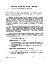
There are four generic shapes of paving blocks which<br />
correspond to the four different types of blocks, as stated<br />
below [4&5]:<br />
(a) Group A: Paver blocks with plain vertical faces,<br />
which do not key into each other when paved in<br />
any pattern,<br />
(b) Group B: Paver blocks with alternating plain and<br />
curved/ corrugated vertical faces, which key into<br />
each other along the curve/ corrugated faces,<br />
when paved in any pattern,<br />
(c) Group C: Paver blocks having all faces curved or<br />
corrugated, which key into each other along all the<br />
vertical faces when paved in any pattern, and<br />
(d) Group D: 'L' and 'X' shaped paver blocks which<br />
have all faces curved or corrugated and which key<br />
Pradhan Mantri Gram Sadak Yojana<br />
into each other along all the vertical faces when<br />
paved in any pattern.<br />
The generic shapes and groups of paver blocks<br />
identified into four different types are illustrated in<br />
Figure 1.<br />
Group - A<br />
Group - B<br />
Group - C<br />
Group - D<br />
Figure 1: Typical Shapes of Concrete Paver Blocks<br />
The various aspects dealing with materials, construction<br />
and laying of interlocking concrete block pavement etc.<br />
are described in the following sections.<br />
Materials for Interlocking Concrete Block<br />
Pavement<br />
The quality of materials used, strength of cement<br />
concrete, durability and dimensional tolerance of<br />
paving blocks etc., is of great importance for achieving<br />
the satisfactory quality and performance of block<br />
pavements. All these aspects including the block<br />
manufacturing process, which immensely affect the<br />
quality of paving blocks, have been outlined in the<br />
Indian Roads Congress Special Publication [7]. In<br />
addition, a specification on Precast Concrete Blocks for<br />
Paving, has recently been published by the Bureau of<br />
Indian Standards [8].<br />
Paving Blocks<br />
The recommended thickness of blocks; grades of<br />
concrete for various applications; specifications of<br />
<strong>Grameen</strong> <strong>Sampark</strong> 7
8<br />
materials used for production of blocks; physical<br />
requirement, test methods, sampling and acceptance<br />
criteria etc., have already been presented in BIS Code<br />
[8].<br />
Bedding Sand and Joint Filling Sand<br />
It is a well established fact that if proper attention is not<br />
paid to the quality of bedding sand, and if the thickness<br />
of bedding sand layer is not kept uniform, serious<br />
irregularities in surface profile can occur result and<br />
consequently excessive differential deformations and<br />
rutting can early in the service life of block pavement.<br />
The gaps in between the two adjacent paving blocks<br />
(typically about 3 mm wide) need to be filled in with<br />
sand which should relatively be finer than the bedding<br />
sand. The gradations of bedding sand and joint filling<br />
sand are given in Table 1.<br />
It is necessary to restrict the fines (silt and/ or clay,<br />
passing 75 micron sieve) to about 10 percent, since<br />
excessive fines make joint filling very difficult. Similarly,<br />
it is not advisable to use cement in the joint filling sand,<br />
which would not only make difficult to completely fill<br />
the joints, but may also adversely affect the desired<br />
flexibility characteristics of the paving block layer. The<br />
joint filling sand should preferably be as dry as possible;<br />
otherwise complete filling of joints will be difficult [7].<br />
Table 1: Gradations of Bedding Sand and<br />
Joint Filling Sand<br />
IS Sieve Size Bedding Sand Joint Filling Sand<br />
Percent Passing by Weight<br />
9.52 mm 100 -<br />
4.75 mm 95-100 -<br />
2.36 mm 80-100 100<br />
1.18 mm 50-95 90-100<br />
600 micron 25-60 60-90<br />
300 micron 10-30 30-60<br />
150 micron 0-15 15-30<br />
75 micron 0-10 0-10<br />
<strong>Grameen</strong> <strong>Sampark</strong><br />
Base and Sub Base Materials<br />
The main purpose of providing base materials are the<br />
load spreading properties to disperse stresses to the<br />
subgrade level and to provide the desired drainage<br />
characteristics, which would have significant bearing<br />
on performance of a block pavement. Although, local<br />
availability and economics generally dictate the choice<br />
of base materials at the design stage, yet the commonly<br />
used materials considered suitable for base courses are<br />
unbound crushed rock, water-bound macadam, wet<br />
mix macadam, cement bound crushed rock/ granular<br />
materials, and lean cement concrete/ dry lean concrete<br />
etc. In broad terms, wherever the subgrade is weak (CBR<br />
value below 5), the use of bound granular materials,<br />
like, cement treated crushed rock, should be preferred
while for high strength subgrade, unbound crushed<br />
rocks may be used. The climatic and environmental<br />
factors also need to be considered during the choice of<br />
base materials. Sub-base is essential where commercial<br />
traffic is expected. The quality of sub-base materials is<br />
inferior to the base materials and may include natural<br />
gravels, cement treated gravels, sands and stabilized<br />
subgrade materials etc. The quality of sub-base<br />
materials should be in conformance with IRC: 37-2001.<br />
Construction of Interlocking Concrete Block<br />
Pavement<br />
Sequencing of Laying Operations<br />
The sequencing of laying operations (Figure-2) for<br />
construction of block pavement should be as follows<br />
[8]:<br />
(i) Installation of sub-surface drainage structures<br />
Basecourse<br />
compacted<br />
and inspected<br />
Beddind sand<br />
slockpited ahead<br />
of screeding<br />
Edge restraint constructed on<br />
basecourse<br />
Figure 2: Sequencing of Laying Operations<br />
Sand bedding<br />
course<br />
screeded<br />
Laying face<br />
Paving<br />
Units<br />
laid<br />
Pradhan Mantri Gram Sadak Yojana<br />
(ii) Leveling and compaction of subgrade<br />
(iii) Provision and compaction of sub-base course<br />
(where needed)<br />
(iv) Provision and compaction of base-course and<br />
checking for the correct profile<br />
(v) Installation of edge restraints<br />
(vi) Provision and compaction of bedding sand<br />
(vii) Laying of blocks and interlocking<br />
(viii) Application of joint sealing sand and compaction<br />
(ix) Cleaning of surface<br />
(x) Filling any remaining empty portions in the block<br />
layer, especially near edge restraint blocks with in<br />
situ concrete.<br />
Cut infill<br />
units<br />
Paving Joint-filling<br />
Units sand<br />
compacted placed<br />
Pavement<br />
completed<br />
allowing access<br />
Pallets of paving units placed as<br />
close as possible to work-lace<br />
Site access and starting point<br />
<strong>Grameen</strong> <strong>Sampark</strong> 9
10<br />
Construction of Sub grade<br />
This is the foundation layer over which the block<br />
pavement is constructed. Like in conventional<br />
pavements, the depth of water table should not be at a<br />
level of 600 mm or higher, below the subgrade level. It<br />
should be compacted in layers of 150 mm thickness.<br />
The prepared subgrade should be graded and surface<br />
dressed to a tolerance of ± 20 mm of the design levels,<br />
and its surface evenness should have a tolerance of<br />
within 15 mm under a 3 m straight edge [7].<br />
Construction of Base and Sub-base Layers<br />
Base course and Sub-base course are constructed in<br />
accordance with the standard procedures contained in<br />
relevant IRC specifications like IRC:37-2001; IRC:50-<br />
1973; IRC:51-1993; IRC:63-1976; IRC:19-1997. When<br />
cement treated bound base is proposed it may be<br />
constructed using rolled dry lean concrete as IRC:SP-<br />
49-1998. The quality control methods, as specified in<br />
IRC: SP-11-1988 shall apply. Constructing these layers<br />
to the proper level and grade is very much essential to<br />
maintain the top surface level and surface regularity of<br />
the block pavement surface.<br />
<strong>Grameen</strong> <strong>Sampark</strong><br />
Edge Restraint Blocks and Kerbs<br />
Concrete blocks subjected to traffic tend to move<br />
sideways and forward due to braking and maneuvering<br />
of vehicles. The tendency to move sideways has to be<br />
counteracted at edges by provisions of special edge<br />
blocks and kerbs. The edge blocks should be designed<br />
and anchored to the base such that the rotation or<br />
displacement of blocks is resisted [7]. These blocks are<br />
to be made of high strength concrete for withstanding<br />
the traffic wheel-loads without getting damaged. These<br />
members should be manufactured or constructed in-situ<br />
in order to have at least a 28-days characteristic<br />
compressive strength of 30 MPa or flexural strength of<br />
3.8 MPa. As far as possible, the edge blocks should have<br />
vertical face towards the inside blocks. Where the space<br />
does not easily permit the use of plate vibrators,<br />
dhurmut or manual compactor using small size plate<br />
rammer may be used. The road kerbs provided on edges<br />
of roads also serve the purpose of edge blocks. In case<br />
the kerbs are not provided, it has to be replaced by the<br />
edge strips. In case of heavy traffic, 150 mm x 150 mm<br />
(height x width) plain cement concrete (M-25) may also<br />
be provided over dry lean concrete to give further<br />
confinement to the blocks. In-between the edgerestraint<br />
blocks, cement mortar (1: 6, cement: coarse<br />
sand) may be used in place of sand for sealing of blocks.<br />
Placing and Screeding of Bedding Sand<br />
The thickness of sand bedding after compaction should<br />
be in the range of 20-40 mm, whereas, in the loose form,<br />
it should be 25 to 50 mm. It is preferable to restrict the<br />
compacted thickness to about 20-25 mm to reduce the<br />
risk of any localized over-compaction, which would<br />
affect the final block surface level. Bedding sand should<br />
not be used to fill-up local depressions on the surface of<br />
base or sub-base layers. The depressions, if any, should<br />
be repaired with same base or sub-base material in<br />
advance before placing the sand. The sand of specified<br />
gradation, should be uniformly in loose condition, and<br />
should have uniform moisture content. Optimum<br />
moisture content is when sand is neither too wet nor too<br />
dry and has moisture of about 6 to 8 percent.
Requirement of sand for a day's work should be<br />
prepared and stored in advance and covered with<br />
tarpaulin or polythene sheets. The processed sand so<br />
obtained is spread with the help of screed boards to the<br />
specified thickness and levels. The screed boards are<br />
provided with nails at 2-3 m apart which when dragged<br />
gives the required thickness. The length of nail should<br />
take into account the surcharge to be provided in the<br />
uncompacted thickness. Alternatively, the screed can<br />
be dragged on edge strips kept on both sides as guides<br />
[7].<br />
Laying of Paving Blocks<br />
Blocks can be laid generally by manual labour but<br />
mechanical aids like hand-pushed trolleys can expedite<br />
the work. Normally, laying should commence from the<br />
edge strips and proceed towards the central line. When<br />
dentated blocks are used, the laying done at two fronts<br />
will create problem for matching joints in the middle.<br />
Hence, as far as possible, laying should proceed in one<br />
direction only, along the entire width or area to be<br />
paved [8].<br />
Pradhan Mantri Gram Sadak Yojana<br />
While locating the starting line, the following should be<br />
considered:<br />
<br />
<br />
<br />
On a sloping site, start from the lowest point and<br />
proceed to up-slope on a continuous basis, to<br />
avoid down-slope creep in incomplete areas.<br />
In case of irregular shaped edge restraints or strips,<br />
it is better to start from straight string line.<br />
Influence of alignment of edge restraints on<br />
achieving and maintaining the laying bond.<br />
Laying Patterns<br />
The blocks can be placed in different bonds or patterns<br />
depending upon the specific requirements. Some<br />
popular bonds commonly adopted for block paving are:<br />
(i) Stretcher or running bond (ii) Herringbone bond and<br />
(iii) Basket weave or parquet bond etc. The typical<br />
layouts of these bonds are given in Figure 3.<br />
O<br />
(a) Stretcher or Running Bond (b) Parquet or Basket Weave (c) 45 Herringbone Bond<br />
O<br />
(d) 90 Herringbone Bond<br />
(e) Parquet Derivative (f) Double - V<br />
(g) Double Herringbone (h) Herringbone (i) Herringbone Bond<br />
Figure 3: Laying Patterns of Paving Blocks<br />
<strong>Grameen</strong> <strong>Sampark</strong> 11
12<br />
Typical Pavement Compositions<br />
Typical compositions normally used in ICBP technology are given in Table-2 with typical cross sections as shown in<br />
Figure 4.<br />
<strong>Grameen</strong> <strong>Sampark</strong><br />
BLOCK PAVED<br />
SURFACE<br />
BASE COURSE<br />
SUBGRADE<br />
Figure 4: Typical Pavement Structure Drainage<br />
JOINT FILLING FINE SAND<br />
INTERLOCKING CONCRETE BLOCK<br />
COARSE BEDDING SAND<br />
Table 2: Catalogue for Pavement Thickness<br />
EDGE RESTRAINT<br />
SHOULDER<br />
Traffic and Road Type Materials >10<br />
Sub grade CBR (%)<br />
5-10<br />
Thickness (mm)<br />
Block Pavement at Typical Locations<br />
Essentially, there are three important aspects in<br />
detailing. These are: (i) Curves (ii) Intrusions, and (iii)<br />
Changes in alignment<br />
Curves: It is necessary to cut the paving units to fit the<br />
edge restraints. Rectangular blocks of similar or<br />
contrasting colour as an edging have been used to<br />
minimize the visual effects of small errors in block<br />
cutting. To avoid unsightly and potentially weak joints,<br />
it is often preferred to change the laying pattern at the<br />
curves. The curve itself can be installed in Herringbone<br />
bond and yet the pavement can revert to stretcher bond<br />
on the approaches [4 & 5].<br />
Intrusions:<br />
On some pavements, like in city streets,<br />
there could be several intrusions, like, manholes,<br />
drainage gulleys, etc. where coping with these<br />
intrusions with the pavement is desirable. Around<br />
intrusions, it is good practice to lay blocks along both<br />
sides of the intrusion simultaneously so that closure is<br />
made away from the starting workface, rather than<br />
carrying the pavement around the intrusion to return to<br />
the original laying face to avoid accumulation of closing<br />
error [7].<br />
Compaction<br />
For compaction of sand bedding and paving blocks laid<br />
over it, the vibratory plate compactors are used over the<br />
laid paving blocks; at least two passes of the vibratory<br />
plate compactors are needed. Such vibratory<br />
compaction should be continued until the top of each<br />
paving block is in level with the adjacent blocks. It is not<br />
a good practice to leave compaction till the end of the<br />
day, as some blocks may move under construction<br />
traffic, resulting in the widening of joints and corner<br />
contact of blocks, which may cause spalling or cracking<br />
of the blocks. There should not be any delay in the<br />
compaction after paving blocks have been laid. This is<br />
necessary to achieve uniformity of compaction and<br />
retention of the pattern of laying. During compaction of<br />
the blocks laid, some amount of bedding sand may get<br />
filled up into the joints between them; the extent of sand<br />
Pradhan Mantri Gram Sadak Yojana<br />
getting filled up into the joints will depend on the degree<br />
of compaction of sand, i.e. the force applied by the<br />
compactor. Standard compactors may have a weight of<br />
about 90 kg with plate area of about <strong>0.</strong>3 m2 and apply a<br />
centrifugal force of about 15 kN. On the other hand,<br />
heavy duty compactors may weigh 300-600 kg, with<br />
plate area of about <strong>0.</strong>5-<strong>0.</strong>6 m2 and apply a centrifugal<br />
force of 30-65 kN. Where the bedding sand is required<br />
to be compacted for heavily trafficed pavements, heavyduty<br />
compactors should be used. After compaction by<br />
vibratory plate compactors, some 2 to 6 passes of<br />
vibratory roller (with rubber coated drums or those of<br />
static weight less than 4 tonne and nominal amplitude of<br />
not more than <strong>0.</strong>6 mm) will further help in compaction<br />
of bedding sand and joint filling [7].<br />
Laying and Surface Tolerances<br />
While constructing the block pavement, the surface<br />
toleranes of individual layers may be observed, as<br />
indicated in IRC:SP:63-2004.<br />
Conclusion<br />
<br />
<br />
<br />
ICBP technology is gaining importance and is<br />
becoming more popular day-by-day because it is<br />
user friendly and requires less infrastructure in<br />
terms of construction equipment / machineries, as<br />
compared to the conventional flexible and rigid<br />
pavements.<br />
ICBP technology can provide durable and<br />
sustainable road infrastructure where construction<br />
and maintenance of conventional pavements are<br />
not cost effective.<br />
ICBP is much cheaper than the rigid (concrete)<br />
pavement, designed for identical operating<br />
conditions. Compared to the bituminous<br />
pavement for low traffic volume roads and high<br />
strength subgrade, the initial construction cost of<br />
ICBP is likely to be equal to or marginally higher.<br />
For high traffic volume roads and low strength<br />
subgrade, ICBP will be cheaper than the flexible<br />
pavement.<br />
<strong>Grameen</strong> <strong>Sampark</strong> 13
14<br />
<br />
<br />
<br />
<br />
Guidelines for the use of Interlocking Concrete<br />
Block Pavement and Precast Blocks for Paving-<br />
Specification are now available in India for<br />
production of better quality paving blocks and<br />
construction of such pavements.<br />
Code of practice for laying and construction of<br />
Interlocking Concrete Block Pavements has been<br />
submitted to Bureau of Indian Standards, which<br />
will be very useful for Indian industries and<br />
highway professions for adoption of block<br />
pavement technology in India, on a large scale.<br />
ICBP technology can help in conservation of<br />
naturally occurring materials like soils, gravels and<br />
aggregates which are now becoming scarce due to<br />
large scale construction activities taking place<br />
throughout the country.<br />
ICBP technology can replace concrete pavements<br />
at least in case of low trafficked roads, to start with.<br />
Road departments and the construction industry<br />
must, therefore, seriously consider ICBP<br />
technology as a potential technology for the<br />
purpose of providing roads in the rural areas.<br />
References<br />
1. Road Development Plan:2001, Ministry of Road<br />
Transport & Highways, Published by Indian Roads<br />
Congress, 2001.<br />
2. Sikdar, P.K., Pradhan Mantri Gram Sadak Yojana A<br />
Mission for Rural Connectivity by All-Weather<br />
<strong>Grameen</strong> <strong>Sampark</strong><br />
Roads, Indian Highways, Vol. 29, No. 5, May<br />
2001.<br />
3. Sikdar, P.K. Pradhan Mantri Gram Sadak Yojana<br />
For the People, By the People, Indian Highways,<br />
Vol. 30, No. 6, June 2002.<br />
4. Sikdar, P.K., Sharma, S.D., Sood, V.K., (2004),<br />
“Interlocking Block Pavement For Sustainable<br />
Road Infrastructure For Cold Region”,<br />
International Conference on Sustainable Habitat<br />
For Cold Climates, Leh, India, September 16-18,<br />
2004.<br />
5. Sharma, S.D., Sikdar, P.K., Rao, Y.V., (2004)<br />
“Interlocking Concrete Block Pavements Its<br />
Prospects”, Seminar on Design, Construction and<br />
Maintenance of Cement Concrete Pavements,<br />
IRC, October, 2004.<br />
6. Muraleedharan, T. and Nanda, P.K., (1992)<br />
“Application and Performance of Interlocking<br />
Concrete Block Pavement An Overview”. The<br />
Indian Concrete Journal, pp 395 -400, July 1992.<br />
7. IRC SP: 63-2004 “Guidelines For Use of<br />
Interlocking Concrete Block Pavement” Indian<br />
Roads Congress.<br />
8. “Indian Standard Specification for Precast<br />
Concrete Paver Blocks”, Bureau of Indian<br />
Standards, Modified 3rd Draft, January 2004.<br />
(Under Publication).
U. C. Sahoo*, M. Amaranatha Reddy** and K. Sudhakar Reddy***<br />
If the selection of pavement layer thickness is dependent<br />
entirely on past experiences gathered about the<br />
performance of in-service pavements, the resulting<br />
design methods are usually termed as empirical<br />
methods. Even in these procedures, there is normally a<br />
distress mode selected (usually rutting) for designing<br />
thickness and will be selected based on the experience<br />
of pavements that have developed acceptable levels of<br />
rutting during their design life period. As these are not<br />
based on any fundamental mechanistic principles that<br />
govern the stress-strain behaviour of the pavement<br />
components, extrapolation of the design procedures<br />
has to be done to situations where new pavement<br />
materials are used, climatic conditions are different<br />
from those prevailing during past experience etc.<br />
Counting efforts are being made for rationalizing the<br />
pavement design procedures by reducing the empirical<br />
content and correlating the performance of the<br />
pavements with load associated behaviour of pavement<br />
Pradhan Mantri Gram Sadak Yojana<br />
Performance Criteria for<br />
Design of Low Volume Rural Roads<br />
components. Analytical tools are used in these methods<br />
to analyze pavement structures subjected to traffic<br />
loads. Hence, these methods are often called Analytical<br />
Design Methods or Mechanistic Methods or even<br />
Theoretical Methods. A more appropriate terminology<br />
would be rational Design Procedures as no design<br />
method can be purely analytical or theoretical, as the<br />
analytically determined parameters have to be<br />
correlated with the performance of the pavements,<br />
which can only come from experience.<br />
In these procedures, some mechanistic parameters<br />
(critical stresses, strains, deflections, etc.) that are<br />
considered to be causative of (or having strong<br />
correlation with) pavement distresses (fatigue cracking,<br />
permanent deformation, etc.) are identified and<br />
correlations are developed between these analytical<br />
parameters and pavement life. The common forms of<br />
structural distresses considered are fatigue cracking of<br />
bound layers and permanent deformation in different<br />
*Research Scholar, Civil Engineering Department, IIT Kharagpur (ucsahoo@civil.iitkgp.ernet.in)<br />
**Assistant Professor, Civil Engineering Department, IIT Kharagpur (manreddy@civil.iitkgp.ernet.in)<br />
***Professor, Civil Engineering Department, IIT Kharagpur (ksreddy@civil.iitkgp.ernet.in)<br />
nd th<br />
Reprinted from the proceedings of National Conference on Rural Roads (22 to 24 May 07) New Delhi<br />
<strong>Grameen</strong> <strong>Sampark</strong> 15
16<br />
layers due to repeated application of traffic wheel loads.<br />
Most of the existing analytical design procedures have<br />
performance criteria that give limiting strain (identified<br />
critical strain parameter) values to ensure that the extent<br />
of structural distress during the service life of pavement<br />
will not exceed acceptable levels.<br />
Any rational pavement design method should have the<br />
following main components:<br />
a) Identification of critical distress parameters for<br />
defining the performance of the pavement. These<br />
can be in terms of surface profile parameters such<br />
as roughness (Fifth Wheel Bump Integrator,<br />
International Roughness Index etc.) mostly<br />
reflecting the functional performance of the<br />
pavement. The performance parameters can also<br />
be in terms of structural distresses such as cracking<br />
of bound layers and rutting in different layers or<br />
even a combined index such as the Present<br />
Serviceability (PSI) used by AASTHO.<br />
<strong>Grameen</strong> <strong>Sampark</strong><br />
b) Selection of proper performance criteria<br />
developed by correlating the observed<br />
performance of pavements with carefully chosen<br />
performance parameters. While performance has<br />
to be defined in terms of the traffic that can be<br />
handled by the pavement before excess failures or<br />
distresses occur, the parameters selected for<br />
explaining the performance (distress or failure) can<br />
be a combination of various pavement parameters<br />
(thicknesses, material properties etc.) or a<br />
combination of critical mechanistic parameters<br />
(deflection, stresses and strains).<br />
c) A framework or a list of steps specifying as to how<br />
the parameters can be selected and/or computed.<br />
The rationality of the design procedure can be judged<br />
from the way corresponding performance criteria have<br />
been developed. The criterion is generally developed<br />
considering a failure condition, which may be any<br />
structural or functional failure or both. The rural roads in
India mostly consist of granular pavements with thin<br />
bituminous surfacing, in which rutting is considered as<br />
the only mode of failure. This is attributed to the vertical<br />
compressive strain at the top of subgrade layer.<br />
Several highway organizations have developed their<br />
own failure condition and performance criterion for<br />
design of low-volume roads. In this study, the criteria<br />
developed by AASTHO, AustRoads, Asphalt Institute<br />
TRRL, etc. have been discussed.<br />
Performance and Failure Criteria for<br />
Pavement Design<br />
In mechanistic design methods, the limiting values of<br />
stresses and/or strains at which a given degree of distress<br />
will occur are commonly known as the performance<br />
criteria. The rationality of the design procedure can be<br />
judged from the way the corresponding performance<br />
criteria have been developed. Performance criterion is<br />
generally developed considering a failure condition,<br />
which may be any structural or functional failure or<br />
both. Fatigue cracking of bituminous surfacing and<br />
permanent deformation (rutting) along wheel paths,<br />
mainly due to repeated application of traffic loads, have<br />
been identified as the two major modes of structural<br />
failures that need to be addressed in the structural<br />
design of pavements. Some performance criteria also<br />
use roughness as the mode of failure in terms of present<br />
serviceability index (PSI) [1]. The low-volume rural<br />
Pradhan Mantri Gram Sadak Yojana<br />
roads in India mostly consist of granular pavements with<br />
thin bituminous surfacing, in which rutting is<br />
considered as the only mode of failure, which occurs<br />
due to vertical compressive strain at the top of subgrade.<br />
In this paper, the rutting criteria adopted by different<br />
highway organizations for design of low-volume road<br />
pavements have been presented with the objective of<br />
comparing these criteria with that adopted for design of<br />
Indian roads.<br />
Selection of Critical Performance Parameters<br />
Horizontal tensile strain at the bottom fibre of<br />
bituminous bound layer and vertical compressive strain<br />
on top of subgrade have traditionally been taken to be<br />
causative for the two major modes of failures<br />
considered, i.e., fatigue cracking and rutting. Excessive<br />
strains applied repeatedly have been considered to be<br />
the major factors for the development of the two modes<br />
of failures. Figure 1 shows a typical layered flexibile<br />
pavement system subjected to a dual wheel loading<br />
applied at the surface.<br />
Deformation or rutting provides the principal indication<br />
of deterioration in granular pavements with thin<br />
bituminous surfacing. It develops chiefly in the wheel<br />
tracks,and increases with time or more precisely with<br />
the cumulative application of commercial traffic.<br />
Bituminous Surfacing<br />
Granular Base<br />
Granular Sub-base<br />
Subgrade<br />
Figure 1: Critical mechanistic parameters<br />
ε z<br />
ε E t 1,µ 1<br />
E, 2 µ 2<br />
E, 3 µ 3<br />
E, 4 µ 4<br />
<strong>Grameen</strong> <strong>Sampark</strong> 17
18<br />
Subgrade Failure Criterion<br />
The basic design thickness in the case of low-volume<br />
roads is the thickness of unbound granular material,<br />
which will limit the vertical compressive strain on top of<br />
the subgrade to an acceptable level. The strain induced<br />
in the subgrade by moving wheel load is mostly elastic<br />
(recoverable). However, the accumulation of the<br />
irrecoverable part of strain leads to permanent<br />
deformation in subgrade. The permanent deformation<br />
manifests at the surface of the pavement as rutting in the<br />
wheel paths, although due to inherent variability of the<br />
subgrade and pavement materials and the construction<br />
techniques, surface roughness develops along with<br />
rutting.<br />
Performance Criteria Addopted By Different<br />
Organizations<br />
AustRoads Design for granular pavements with thin<br />
bituminous surfacing [2 3]<br />
The limiting strain criterion for the subgrade is given by<br />
Eq. 1. It was derived by applying mechanistic procedure<br />
to a range of pavements.<br />
Where,<br />
7.14<br />
N = [8511/ µ ] (1)<br />
µ <br />
<strong>Grameen</strong> <strong>Sampark</strong><br />
= vertical compressive strain (microstrain)<br />
at the top of the subgrade<br />
N = allowable number of repetitions of the<br />
strain before unacceptable level of<br />
rutting develops.<br />
Implicit in the design procedure for granular pavements<br />
with thin bituminous surfacing, is a terminal condition<br />
which is considered to be unacceptable and hence<br />
signifies the end of life of the pavement. The terminal<br />
condition is considered to be an average rut depth of<br />
about 20mm, and terminal roughness about three times<br />
the initial roughness.<br />
AASHTO Low Volume Road Design Procedure [1]<br />
The low-volume road design procedure used by<br />
AASHTO is based on lower level of reliability (50%)<br />
because of their low usage and associated low level of<br />
risk. Predicted future traffic, seasonal resilient moduli of<br />
roadbed soil, elastic modulus of aggregate base and<br />
subbase layer, design serviceability loss, allowable<br />
rutting and aggregate loss (GL) of surface course are the<br />
main input for the design of low volume roads.<br />
Common values for terminal serviceability index are<br />
Pt=2.<strong>0.</strong> For minor highways like aggregate surfaced<br />
roads, where funds or economy is the main factor, the<br />
design is done by reducing the traffic or design life rather<br />
than reducing the terminal serviceability to a number<br />
lower than 2.0<strong>0.</strong> Aggregate loss due to traffic and<br />
erosion should be considered in the design and this may<br />
be calculated using any of the following equations 2, 3<br />
and 4.<br />
According to a study by University of Texas at Austin:<br />
Where,<br />
GL = <strong>0.</strong>12 + <strong>0.</strong>1223 (LT) (2)<br />
GL = Total Aggregate loss in inches;<br />
LT = Number of loaded trucks in<br />
thousands<br />
Another study in Brazil formulated the following<br />
equation:<br />
GL = (B/25.4)/ (<strong>0.</strong>0045LADT + 338<strong>0.</strong>6/R +<br />
<strong>0.</strong>467G) (3)
Where,<br />
GL = Total Aggregate loss in inches during the<br />
period of time being considered;<br />
B = Number of blading during the period of<br />
time being considered;<br />
LADT = Avg. daily traffic in the design lane;<br />
R = Avg. radius of curve, in feet, and;<br />
G = Absolute value of grade, in percent<br />
British study done in Kenya is more applicable to areas<br />
with little truck activity and is given below:<br />
Where,<br />
AGL =<br />
2 2 2<br />
[T /(T + 50] * f (4.2 +<strong>0.</strong>092T +<strong>0.</strong>889R +<br />
1.88VC) (4)<br />
AGL = Annual aggregate loss, in inches;<br />
T = Annual traffic volume in both directions,<br />
in thousands of vehicles;<br />
R = Annual rainfall, in inches;<br />
Pradhan Mantri Gram Sadak Yojana<br />
VC = Average percentage gradient of the road,<br />
and<br />
f = <strong>0.</strong>037 for lateritic gravels; <strong>0.</strong>043 for<br />
quartzite gravels, <strong>0.</strong>028 for volcanic<br />
gravels, and <strong>0.</strong>059 for coral gravels.<br />
Rutting is bound to occur in average surfaced roads, and<br />
is considered as performance criteria for these roads.<br />
The typical value of allowable rut depth for designing an<br />
aggregate surfaced road falls between 1.00 and 2.00<br />
inches.<br />
Design charts are available to estimate the required<br />
thickness of aggregate surfaced roads for low volume<br />
roads.<br />
Vermont Agency of Transportation [4] procedure for the<br />
design of low-volume pavement structures is based on<br />
the 1993 AASHTO Guide for Design of Pavement<br />
Structures. The following performance indicators in<br />
terms of PSI were used:<br />
For paved roads, initial PSI = 4.0 and terminal PSI = 2.0<br />
and for unpaved roads, initial PSI = 4.0 and terminal PSI<br />
= 1.0<br />
<strong>Grameen</strong> <strong>Sampark</strong> 19
20<br />
A maximum of 50mm rut depth was recommended for<br />
the unpaved roads. The reliability adopted is 50%.<br />
Asphalt Institute [5] adopted the following subgrade<br />
strain criteria<br />
<br />
Where,<br />
<strong>Grameen</strong> <strong>Sampark</strong><br />
-2 <strong>0.</strong>223<br />
= 1.05*10 *[1/N] (5)<br />
N = No of 80 kN equivalent single axle loads;<br />
<br />
Z<br />
Z<br />
= Vertical subgrade strain ( micro strain) at<br />
top of the subgrade layer<br />
TRRL [6] considers the following relationship to<br />
complete allowable subgrade strains for 85 percent<br />
probability of survival to a design life of N repetitions of<br />
o<br />
80kN axle and a pavement temperature of 20 C.<br />
Log (N) = -7.21-3.95* log ( ) (6)<br />
Z<br />
The failure condition considered for the above criteria is<br />
rutting of 20 mm<br />
The Shell [7] design method uses the following<br />
subgrade strain for different confidence levels:<br />
-2 -<strong>0.</strong>25<br />
50% confidence = 2.8*10 *N (7)<br />
Z<br />
-2 -<strong>0.</strong>25<br />
85% confidence = 2.1*10 *N (8)<br />
Z<br />
-2 -<strong>0.</strong>25<br />
95% confidence = 1.8*10 *N (9)<br />
Z<br />
A terminal value of percent serviceability (PSI) of 2.5<br />
was taken as failure condition.<br />
Indian Road Congress (IRC 37:2001) [8] adopted the<br />
following performance criteria for high volume roads.<br />
N R =<br />
-8 4.5337<br />
4.1656*10 [1/ Z ] (10)<br />
N R = Number of cumulative standard axels to<br />
produce rutting of 20 mm.<br />
<br />
Z<br />
= Vertical subgrade strain (micro strain).<br />
Development of an average rut depth of about 20 mm is<br />
considered to be failure in rutting mode.<br />
IRC:SP:20:2002 [9] is for design of low-volume rural<br />
roads in India. The criterion for determining the<br />
thickness of a flexible pavement with a thin bituminous<br />
surfacing is the vertical compressive strain on top of the<br />
subgrade imposed by a standard axle load (80kN). The<br />
maximum rutting allowed is 50mm before any<br />
rehabilitation work is taken up. The design charts have<br />
reportedly been prepared as per Road Note 29 of TRL,<br />
IRC: 37 and other related experiences in India. No<br />
mechanistic rutting criterion has been proposed<br />
correlating the design life with subgrade strain or any<br />
other parameter.<br />
Mohanty et al [10] studied the performance of 59 village<br />
road sections in Orissa and proposed some design<br />
charts for construction of new low-volume rural roads.<br />
The pavement condition data collected on these<br />
sections were correlated with mechanistic response of<br />
the pavement to develop a performance criteria based<br />
on limiting rutting value.
Where,<br />
-11 5.44<br />
N = 3.42 x 10 (1/ ) (11)<br />
N = Number of standard axle repetitions to<br />
cause 50 mm rutting;<br />
<br />
V<br />
= Vertical sub grade strain<br />
Performance criterion is the most important aspect<br />
considered in the design of pavements and all rational<br />
design methods must have properly developed<br />
performance criteria. It is seen that most of the design<br />
methods in vogue have design criteria mostly in terms of<br />
subgrade strain and aim to control rutting. The main<br />
concerns with the design practices followed in India are<br />
that either they do not have performance critferia or<br />
even if there is mention of performance criteria there is<br />
not much evidence of the criteria having been<br />
developed on the basis of sufficient data. This<br />
emphasizes the need for collection of data on the<br />
performance of different types of low-volume roads on a<br />
long term basis. The recent initiative taken by NRRDA<br />
for collection of performance data on the recently<br />
constructed PMGSY will go a long way in filling this<br />
major void in the low-volume road design in India.<br />
References<br />
1. American Association of State Highway and<br />
Transportation Officials, “AASHTO Guide for<br />
Design of Pavement Structures 1993, AASHTO,<br />
Washington, D.C.<br />
2. Austroads Pavement Research Group 1998, A<br />
guide to the design of new pavements for light<br />
traffic: a supplement to Astroads pavement design,<br />
APRG Report No. 21, ARRB Transport Research,<br />
Vermont South, Victoria.<br />
3. Austroads, Pavement design a guide to the<br />
structural design of road pavements, AP-17/92,<br />
Austroads, Sydney, 1992.<br />
4. Vermont Agency of Transportation, “Low Volume<br />
Pavement Design Procedure”, Vermont Agency of<br />
Transportation, Montpelier, VT, March 2002<br />
V<br />
Pradhan Mantri Gram Sadak Yojana<br />
5. Ibid. Shook J.F., Finn F. N.., Witczak M. W. and<br />
Monismith C. L., “Thickness Design of Asphalt<br />
Pavements The Asphalt Institute Method, pp. 17-<br />
44.<br />
6. Lister N. W. and Powell W. D., “ Design Practice<br />
for Bituminous Pavements in United Kingdom”<br />
Proc. 6th International Conference on Structural<br />
Design of Asphalt Pavements”, Vol-1, 1987, pp.<br />
220-231.<br />
7. Gerristen A. H. and Koole R. C. “Seven Years'<br />
experience with the structural aspects of the Shell<br />
Pavement Design Manual”, Proc. 6th International<br />
Conference on Structural Design Asphalt<br />
Pavements”, Vol-1 1987, pp. 94-106.<br />
8. Indian Road Congress, IRC:37:2001 Guidelines<br />
for Design of Flexible Pavements, New Delhi,<br />
2001.<br />
9. Indian Road Congress, IRC:SP:20-2002 Rural<br />
Roads Manual, 2002, New Delhi.<br />
1<strong>0.</strong> Mohanty S. K., Reddy K. S. and Pandey B. B..,<br />
“Performance and Design of Village Roads”,<br />
Highway Research Bulletin No. 55, IRC, 1996, pp.<br />
66-84.<br />
<strong>Grameen</strong> <strong>Sampark</strong> 21
22<br />
Stabilization of Soil Subgrade<br />
with Polypropylene Fibres<br />
Dr. I.K.Pateriya* and Dr. K. A. Patil**<br />
In India, transportation is mainly by roads. Only roads<br />
can access very small villages, remote areas and hilly<br />
areas. Hence, considerable attention is required<br />
towards the widening of roads, their suitability and<br />
periodic repair works. Most state highways in the<br />
central part of India have problems of foundation for<br />
highway embankments, bridge abutments, retaining<br />
walls and earth dams with steep slopes have been built<br />
using different types of reinforcements. Hoare(1979)<br />
analyzing the results of a series of laboratory<br />
compression and CBR tests on a sandy gravel reinforced<br />
with randomly distributed synthetic fibres less than 2%<br />
by weight, observed that the presence of fibres<br />
increased the apparent angle of internal friction and<br />
ductility of the soil particularly at low confining stress.<br />
A. Boominathan (1999) carried out some tri-axial<br />
compression tests on sand reinforced with randomly<br />
distributed fibres.<br />
*Joint Director (Technical), NRRDA, Delhi<br />
**Lecturer in Civil Engineering; Govt. College of Engineering, Karad (M.S.) 415 124<br />
<strong>Grameen</strong> <strong>Sampark</strong><br />
Fibre reinforcement technique permits use of natural as<br />
well as synthetic fibres for soil reinforcement. In<br />
Maharashtra black cotton soil is found in abundance<br />
which is highly expansive soil. An attempt has been<br />
made to investigate the use of polypropylene fibres for<br />
improving properties of locally available soil. The<br />
comparison of properties of soil with addition of varying<br />
percentages of fibres by dry weight of soil and having<br />
different aspect ratios is also carried out. The addition of<br />
polypropylene fibres resulted in increase in optimum<br />
moisture content and decrease in maximum dry density.<br />
Direct shear tests conducted on soil shows increase in<br />
value of cohesion and decrease in value of angle of<br />
internal friction. With the inclusion of the fibres increase<br />
in C.B.R. value was observed. The crust thickness of<br />
flexible pavement is appreciably reduced, due to<br />
increase in C.B.R.value of soil subgrade.
EXPERIMENTAL WORK<br />
Materials Used<br />
The soil used in the study was collected from 10 km<br />
distance from Jalna. The soil used was black cotton soil.<br />
Table 1 shows geotechnical properties of soils collected<br />
for experimentation. Polypropylene fibres of average<br />
diameter <strong>0.</strong>25 mm with aspect ratios of 20, 40 and 80<br />
were used.<br />
Sample Preparation<br />
Fibre reinforced soil samples were prepared at<br />
maximum dry density and optimum moisture content<br />
obtained by conducting standard Proctor test on unreinforced<br />
soil and reinforced soil. The fibre reinforced<br />
specimens were prepared by hand mixing the dry soil,<br />
water and polypropylene fibres. The percentage of fibre<br />
used in samples was 1, 2, and 3 percent by dry weight of<br />
soil. The water was added prior to fibre to prevent<br />
floating problems. fibre reinforced soil samples were<br />
prepared at the maximum dry density and the optimum<br />
Table1: Geotechnical properties of soil<br />
Pradhan Mantri Gram Sadak Yojana<br />
moisture content obtained from standard proctor tests<br />
on reinforced soil. Un-drained direct shear tests were<br />
conducted on reinforced samples with varying<br />
percentages of fibres and aspect ratio. California<br />
bearing ratio (C.B.R) tests were conducted under soaked<br />
conditions. Unconfined compression strength tests<br />
were conducted on cylindrical specimen at Proctors<br />
maximum dry density and optimum moisture content.<br />
Specific Liquid Plastic Plasticity Maximum Dry Cohesion Angle of Internal<br />
Gravity Limit % Limit % Index %<br />
3<br />
Density (gm/cm )<br />
2<br />
(kN/m ) Friction (Degrees)<br />
2.49 56 27 29 1.53 34 16<br />
RESULTS AND DISCUSSION<br />
The influence of aspect ratio and fibre concentration on<br />
the properties of soil were studied. The OMC and dry<br />
density test results on black cotton soil with different<br />
aspect ratio and fibre content are reported in Table 2.<br />
These data indicate that maximum dry density<br />
decreases gradually with increase in the fibre content,<br />
which is due to lower density of the fibre than the soil<br />
particles. An increase in Optimum moisture content<br />
was observed due to adsorption of water particles on the<br />
surface of polypropylene fibres.<br />
Table 2: Proctor's test results for un-reinforced and reinforced soil<br />
Sr. No. Description Aspect Ratio % O.M.C MDD (gm/cm3)<br />
1. Soil without reinforcement - 24.6 1.53<br />
2. Soil with 1 % Polypropylene fibres 20 24.7 1.52<br />
3. Soil with 2 % Polypropylene fibres 20 24.9 1.51<br />
4. Soil with 3 % Polypropylene fibres 20 25.1 1.50<br />
5. Soil with 1 % Polypropylene fibres 40 24.8 1.52<br />
6. Soil with 2 % Polypropylene fibres 40 25.0 1.50<br />
7. Soil with 3% Polypropylene fibres 40 25.3 1.48<br />
8. Soil with 1 % Polypropylene fibres 80 24.9 1.50<br />
9. Soil with 2 % Polypropylene fibres 80 25.2 1.47<br />
1<strong>0.</strong> Soil with 3% Polypropylene fibres 80 25.4 1.44<br />
<strong>Grameen</strong> <strong>Sampark</strong> 23
24<br />
Changes in Cohesion and <br />
Direct shear tests were conducted on soil samples in unreinforced<br />
and reinforced conditions. The<br />
<strong>Grameen</strong> <strong>Sampark</strong><br />
reinforcement was added in the range of1%to3%with<br />
varying aspect ratios of 20, 40 and 8<strong>0.</strong> The results<br />
obtained are summarized in Table 3.<br />
Table 3: Effect of reinforcement on shear strength characteristics of soil<br />
Sr. No. Description Aspect Cohesion Increase over <br />
Ratio<br />
2<br />
(kN/m ) % Soil without<br />
Reinforcement<br />
(Degrees)<br />
1. Soil without reinforcement - 34 — 16<br />
2. Soil with 1 % Polypropylene fibres 20 35.4 4.12 15.9<br />
3. Soil with 2 % Polypropylene fibres 20 37.2 9.42 15.6<br />
4. Soil with 3 % Polypropylene fibres 20 36.9 8.53 15.5<br />
5. Soil with 1 % Polypropylene fibres 40 36.3 6.76 16.0<br />
6. Soil with 2 % Polypropylene fibres 40 39.6 16.47 15.8<br />
7. Soil with 3 % Polypropylene fibres 40 38.7 13.82 15.6<br />
8. Soil with 1 % Polypropylene fibres 80 35.8 5.29 15.7<br />
9. Soil with 2 % Polypropylene fibres 80 38.4 12.94 15.4<br />
1<strong>0.</strong> Soil with 3 % Polypropylene fibres 80 37.9 11.47 15.0
From Table 1, it is found that black cotton soil has<br />
2<br />
cohesion (C ) as 34 kN/m and angle of internal friction<br />
( ) as 16 degrees. From Table 3, it is found that due<br />
addition of polypropylene fibres in black cotton soil, for<br />
all aspect ratios of 20, 40 and 80, the cohesion increases<br />
and the angle of internal friction decreases. Due to<br />
addition of 2% polypropylene fibres in black cotton soil,<br />
the cohesion increases by 9.42%, 16.47% and 12.94%<br />
for aspect ratio of 20,40 and 80 respectively. The angle<br />
of internal friction decreases by 2.5%, 1.25% and<br />
3.75% for aspect ratio of 20, 40 and 80 respectively.<br />
Fibre content and aspect ratio governs the shear strength<br />
of fibre reinforced soil. The strength of reinforced soil<br />
increases with an increase in fibre content. The rate of<br />
increase is higher at lower fibre content i.e. less than<br />
2%. At fibre content greater than 2%, the relative gain in<br />
Pradhan Mantri Gram Sadak Yojana<br />
strength is small. This is possibly due to the fact that<br />
fibres of lower specific gravity occupy relatively large<br />
volume in the composite. Thus, with higher fibre<br />
content, the quantity of soil matrix available for holding<br />
the fibres is insufficient to develop an efficient bond<br />
between soil and fibre. above 2% fibre content, the<br />
uniform mixing of soil and fibre is difficult as balling up<br />
of fibre takes place.<br />
Changes in CBR value of soil<br />
Table 4: CBR values for reinforced and un-reinforced soil<br />
The CBR tests were conducted on un-reinforced soil and<br />
soil reinforced with fibre. The tests were carried out after<br />
four days soaking in water. CBR values at different<br />
aspect ratio and varying fibre content are given in table<br />
4 and Fig. 1. The maximum CBR value in present study<br />
was found at aspect ratio of 40 and 2% fibre content.<br />
Sr.No. Description Aspect Ratio Soaked CBR %<br />
Value (%) increase<br />
1. Soil without reinforcement - 3.05 —-<br />
2. Soil with 1 % Polypropylene fibres 20 4.20 37.77<br />
3. Soil with 2 % Polypropylene fibres 20 5.15 68.85<br />
4. Soil with 3 % Polypropylene fibres 20 5.05 65.57<br />
5. Soil with 1 % Polypropylene fibres 40 4.50 47.55<br />
6. Soil with 2 % Polypropylene fibres 40 5.35 75.40<br />
7. Soil with 3 % Polypropylene fibres 40 5.20 7<strong>0.</strong>49<br />
8. Soil with 1 % Polypropylene fibres 80 4.40 44.26<br />
9. Soil with 2 % Polypropylene fibres 80 5.15 68.85<br />
1<strong>0.</strong> Soil with 3 % Polypropylene fibres 80 5.00 63.93<br />
From Table 3, it is found that due addition of 2 %<br />
polypropylene fibres in black cotton soil, the increase in<br />
C.B.R. value is found to be 47.55%, 75.40 % and<br />
7<strong>0.</strong>49 % for aspect ratio of 20, 40 and 80 respectively.<br />
Also, it is observed that on 3% addition of<br />
polypropylene fibres, C.B.R. value is found to be less<br />
than that at 2% fibre content. Hence, 2 % fibre content<br />
with aspect ratio of 40 may be considered as optimum<br />
fibre content.<br />
<strong>Grameen</strong> <strong>Sampark</strong> 25
26<br />
Increase in the C.B.R. value is due to compaction<br />
characteristics of polypropylene fibre reinforced soil.<br />
Higher compaction can be achieved by addition of<br />
fibres with higher aspect ratio up to certain limit. The<br />
design of flexible pavement is governed by C.B.R. value<br />
of subgrade soil. Thus, higher value of C.B.R. for<br />
subgrade soil gives lesser pavement thickness and<br />
proves to be the economical solution in pavement<br />
construction.<br />
% Soaked CBR Value<br />
5.5<br />
5<br />
4.5<br />
4<br />
3.5<br />
3<br />
0 1 2 3<br />
Polypropylene fibres Content<br />
Figure 1: Relationship between polypropylene fibres<br />
content and Soaked % C.B.R. value<br />
<strong>Grameen</strong> <strong>Sampark</strong><br />
1 % fibres 2 % fibres 3 % fibres<br />
Reduction in Crust Thickness of Flexible<br />
Pavement<br />
Thickness of flexible pavement is calculated based on<br />
C.B.R. value of soil subgrade and traffic in terms of ESAL<br />
applications as per SP:72-2007. As the C.B.R. value<br />
increased from 3.05 % to 5.35 %, on addition of 2 %<br />
polypropylene fibres with aspect ratio of 40, the crust<br />
thickness reduces appreciably. Table 5 below, illustrates<br />
the reduction in crust thickness for different ESAL<br />
applications (Traffic categories T4 to T 7of SP 72:2007)<br />
From table 5, it is observed that the design crust<br />
thickness reduces by 75 mm for traffic category T4 and<br />
by 100 mm for traffic categories T5 to T7. The reduction<br />
in crust thickness is partly in the thickness of modified<br />
soil with C.B.R. more than 10 % and partly in the<br />
thickness of granular sub base (GSB).<br />
Conclusions<br />
Based on the limited experimental work done in the<br />
laboratory, following conclusions are drawn:<br />
1. On addition of 2 % polypropylene fibres with<br />
aspect ratio of 40, the soaked C.B.R value can be<br />
improved up to 75 % in comparison with the unreinforced<br />
soil.<br />
2. The crust thickness is reduced by 75 to 100 mm for<br />
different ESAL applications.<br />
References<br />
1. Boominathan A. (1999), “Randomly Distributed<br />
fibre Reinforced Sand”, Short term course on<br />
Geosynthetics and reinforced soil structure,<br />
I.I.T.Madras, India, pp. XVI 1 to XVI 1<strong>0.</strong><br />
2. Meenal Gosavi, K.A.Patil, S.Mittal (2004) Swami<br />
Saran “Improvement of Properties of Soil in<br />
Subgrade by Using Synthetic Reinforcement”<br />
Journal of Institution of Engineers (India), CV, Vol.<br />
84, pp.257-262, February 2004<br />
3. Ranjan Gopal and Charan H.D. (1998) “Randomly<br />
Distributed fibre Reinforced Soil”, IE (I) Journal,<br />
Vol.79, pp. 91-100 .<br />
Table 5: Reduction in Crust Thickness with increase in CBR value<br />
Sr. CBR 1 to 2 Lakhs 2 to 3 Lakhs 3 to 6 Lakhs 6 to 10 Lakhs<br />
No. ESAL (T4 ) ESAL (T5 ) ESAL (T6) ESAL (T7)<br />
1. 3.05 % 375 mm 425 mm 475 mm 525 mm<br />
2. 5.35 % 300 mm 325 mm 375 mm 425 mm
Experiencing Folded Plates in<br />
Roadworks Retaining Structure<br />
Dipankar Chakrabarti*, Shyamalendu Mukherjee**<br />
Road is a high investment sector. The sustainability of<br />
roads results in unobstructed growth. Sustainability of<br />
embankment signifies that its toe does not slip, the slope<br />
is steady and if at all sloped surfaces erode, to some little<br />
extent, the eroded soil particles do not go waste into<br />
ditches/rivulets. In the states like West Bengal, Assam,<br />
Part of Bihar and may be in all other states the rural road<br />
alignments generally follow embankment which had<br />
been previously used as road. The soil of these<br />
embankments was borrowed from close vicinity, some<br />
times even just from areas adjacent to the toe lines. Now<br />
while aiming at widening, raising embankment it is<br />
found that in many stretches the existing mass are under<br />
*Executive Engineer (HQ) WBSRDA,<br />
**Assistant Engineer (Nadia Division) , WBSRDA,West Bengal<br />
Pradhan Mantri Gram Sadak Yojana<br />
threat of slippage into such ditches. The structural<br />
element that we may think about for resisting slippage is<br />
a retaining wall. When it is very low in height and<br />
constructed along the toe line, we may call it as Toe<br />
wall. Cut-off wall is another hidden element, which<br />
plays effective role by resisting moisture entry in the<br />
embankment. A considerable amount of resources is put<br />
in for constructing the retaining walls. Economising this<br />
account shall fetch overall economy. The objective was<br />
to develop a structural system, which would be cost<br />
effective but capable enough to perform as retaining<br />
wall, toe wall or cut-off wall, may be even as Guide<br />
Bank.<br />
<strong>Grameen</strong> <strong>Sampark</strong> 27
28<br />
Laboratory Test (Under Vertical Loading)<br />
A set of tests have been carried out in laboratory to<br />
ascertain the ability to sustain vertical load by a paper in<br />
<strong>Grameen</strong> <strong>Sampark</strong><br />
terms of its own weight when folded to different ratios of<br />
length and breadth of folds corresponding to different<br />
heights. The results obtained are as under:<br />
Test Height (H) Length of Breadth of Self weight Slenderness Length of Sustained Ratio of<br />
No. (in mm) Fold (L) Fold (B) of the Paper Ratio Fold/ Breadth weight Load and<br />
(in mm.) (in mm.) (in gms.) of Fold (L/B) (in gms.) Self weight<br />
I 80 75 25.0 2.56 3.20 3.00 454.00 177.34<br />
II 80 55 27.5 2.56 2.90 2.00 543.00 214.06<br />
III 80 30 1<strong>0.</strong>0 1.28 8.00 3.00 17<strong>0.</strong>00 132.81<br />
IV 66 63 42.0 1.60 1.57 1.50 41<strong>0.</strong>00 256.25<br />
V 143 63 42.0 3.33 3.40 1.50 356.67 107.11<br />
VI 100 80 5<strong>0.</strong>0 1.00 2.00 1.60 238.00 238.00<br />
VII 45 75 2<strong>0.</strong>0 4.00 2.25 3.75 102<strong>0.</strong>00 255.00<br />
VIII 56 60 22.0 8.00 2.54 2.72 1987.00 248.38<br />
IX 180 43 18.0 5.00 1<strong>0.</strong>00 2.39 145.00 29.00<br />
X 150 43 18.0 4.00 8.33 2.39 77<strong>0.</strong>00 197.50<br />
XI 120 43 18.0 4.00 6.67 2.39 947.00 236.75<br />
XII 83 43 18.0 2.00 4.61 2.39 180<strong>0.</strong>00 75<strong>0.</strong>00<br />
It is found from the laboratory tests that when breadth of<br />
fold (B) = <strong>0.</strong>125 times of height (H) and the length of fold<br />
(L) is thrice the breadth of fold the most economical<br />
cross section of the folded plate wall would be adequate<br />
to sustain vertical load upto hundred and thirty three<br />
times (133) that of the self weight of the structure. Which<br />
virtually means that a 3 m. long 250 mm. thick brick<br />
wall of height 3 m., if folded in conformity to the above<br />
parameters of fold, can take load of 580 tons (Self weight<br />
4387 Kgs.). It can sustain load from approximately 800<br />
m2 of roof area. which confirms that if materials of<br />
higher crushing strength could be obtained by<br />
improving quality of material used for folded wall, the<br />
cost for quality improvement might bring much higher<br />
cost benefit ratio.
Laboratory Test on Folded Plate Structure<br />
under Transverse Loading<br />
Structural performance of brick wall is less critical in<br />
compression and more in bending. An attempt was<br />
made for model analysis with cuboids arranged in the<br />
form of Rat Trap Bonded folded structure. Cuboids of<br />
thermocole 12 mm x 20 mm x 40 mm. were made for<br />
the purpose but the attempt was in vain. Since the<br />
thermocole cuboids being very light in weight did not<br />
remain static while the next layers were put in.<br />
Anticipating that wooden cuboids might be better<br />
wooden cuboids are under preparation. About 4500<br />
numbers of wooden cuboids of different dimensions are<br />
needed for a model analysis.<br />
Field Application of Folded Plates<br />
In the district of Nadia in West Bengal a (PMGSY)<br />
Project was initially selected. The road selected was<br />
“Elangi to Lakshmigachha” under Package No.<br />
WB/14/25. There was a pond beside the road at<br />
chainage 5.90 km. It was decided to go for a<br />
performance study of folded plate retaining wall of<br />
Pradhan Mantri Gram Sadak Yojana<br />
height 1.5 m above ground level. The breadth at the<br />
bottom of retaining wall at foundation level was kept 2/3<br />
of the height of retention. A 975 mm wide base plate of<br />
100 mm. thick PCC (1:3:6), was cast. Then a 250 mm<br />
thick brick masonry wall in folded configuration was<br />
constructed. Out of the total length, a stretch was further<br />
enforced with corbelled bricks, five layers (75x5=375<br />
mm) projected to the countryside. The idea was to see<br />
that the mass of earth over the shelf, developed by the<br />
corbelling, would generate a restoring moment which<br />
would minimise the overturning moment.<br />
The folded brick wall was constructed against the<br />
conventional English or Flemish Bond in a new bonding<br />
system called “Rat Trap Bond”. It had been propagated<br />
in India through the efforts of renowned Architect Shri<br />
Laurie Baker .There is a saving of 25% of the total<br />
number of bricks and thus in the cost by using Rat Trap<br />
Bond. Computer simulated test modules have<br />
established that Rat Trap Bond is 25% stronger. The<br />
following comparative statement shows consumption<br />
of basic materials for brick wall by conventional English<br />
Bond and Rat-by-Rat Trap Bond.<br />
Material required<br />
with respect to type of bonding No of Bricks Cement Sand<br />
1 Cum. Brick work 230 th using English Bond 487 62 Kgs. <strong>0.</strong>22 Cum.<br />
1 Cum. Brick work using Rat Trap Bond 370 30 Kgs. <strong>0.</strong>126 Cum.<br />
Folded Plate Folded Plate as Guide Bank<br />
<strong>Grameen</strong> <strong>Sampark</strong> 29
30<br />
Apart from the above, both faces of Rat Trap Bonded<br />
Brick wall are checked with plumb bob, so both the<br />
faces are uniform. As a result there is no necessity to<br />
provide plastering. All that would be required is neat<br />
cement pointing and patching on one edge of the<br />
header course. Hence there will be additional savings in<br />
plastering.<br />
On completion of construction and curing the back<br />
filling was done with, in layers by local earth of<br />
Maximum Dry Density (MDD) 1.70 gms./cc. Then an<br />
earth compactor was employed to roll and compact the<br />
retained earth. The compactor was directed to start<br />
rolling from about 1 m away from the retaining wall and<br />
it came slowly towards the folded wall and went on<br />
rolling moving over the corbelled shelves with full<br />
capacity of vibration, which is equivalent to 36 M.T.<br />
Observations<br />
Through the wall was expected to fail severely, it did<br />
not. The stretches where the relieving shelves were not<br />
in existence, after repetition of about 3-4 cycles of full<br />
vibration rolling the vertical joint at the junction of fold<br />
on the pond side showed a line of crack which<br />
propagated along the line of weakness of brick masonry.<br />
The maximum width of crack was about 35 mm and it<br />
appeared at about 7250 mm from GL i.e. at about at ½ of<br />
height from GL. This clearly signifies that the failure was<br />
due to intensity of rolling load to this enormous extent.<br />
Not by virtue of back filling. The entire operation was<br />
<strong>Grameen</strong> <strong>Sampark</strong><br />
video recorded. A selected portion of video recording is<br />
attached with a soft copy of this document.<br />
Progress of Field Tests<br />
A good number of folded plates were then applied to<br />
different locations of different projects as a cost effective<br />
tool for different height of retentions also. All are<br />
performing satisfactory till date. Some photographs are<br />
attached.<br />
In one instance folded plate has been applied to act as a<br />
guide bank beside a rivulet, which converges and<br />
passes through a narrow vented old culvert at the fag<br />
end of a PMGSY road – Rukunpur Khalshipara to<br />
Bangaljhi Ferry Ghat under Package No. WB/14/27.<br />
The stretch of road at this point would get inundated in<br />
every monsoon. Erosion was a predominant feature in<br />
this stretch. The folded plate brick masonry structure<br />
was used as a guide bank and it performed very well. It is<br />
observed that the fins of the folds acted like small spurs<br />
and the soil started depositing between the fins and<br />
chances of erosion has been reversed.<br />
Analysis of Economics<br />
A cost estimate has been done for three types of<br />
retaining wall 11.45 m. long to retain 1.5 m. high earth.<br />
The types of wall chosen are as under: -<br />
1. Folded plate Rat-Trap Bonded wall.<br />
2. Standard Trapezoidal Brick masonry wall.<br />
3. Standard Trapezoidal Plain Cement Concrete<br />
(1:2:4)<br />
The following table shows the comparative analysis of<br />
the economics of the types of walls.<br />
Type of Wall Cost / running meter<br />
1. Folded plate “Rat-Trap Rs. 1781.25 / m.<br />
bonded wall”<br />
2. Brick masonry retaining Rs. 3498.54 / m.<br />
wall<br />
3. Plain Concrete (1:2;4) Rs. 5104.60 / m.<br />
retaining wall
It shows that the cost of standard brick masonry<br />
retaining wall is almost double and concrete retaining<br />
wall costs 2.865 times more than the folded plate brick<br />
rat-trap bonded retaining wall. Hence, in other words<br />
the savings will be to the tune of 50% and 65 %<br />
respectively.<br />
Structural Analysis<br />
A preliminary analysis shows that the structure is<br />
marginally safe. But from experiment it reveals that the<br />
structure is highly safe. Therefore it can be concluded<br />
that certain parameters are yet to be considered. Further<br />
analysis in this light is being carried out.<br />
Conclusions<br />
Based on the limited experimental work and<br />
observation on some of the structures already<br />
constructed in the field, it can be concluded that:<br />
1. The folded plate structure develops immense<br />
stiffness and sustainability against any and every<br />
kind of loads due to folded configuration.<br />
2. There must be some structural uniqueness<br />
generated within the system, which contributes<br />
additional stiffness.<br />
3. By virtue of this phenomenon the folded plate wall<br />
is found to be more efficient than the degree of<br />
efficiency found out by usual structural<br />
calculations.<br />
4. The folded plate structure is very economical and<br />
can be used safely as retaining walls, cut off walls,<br />
and guide banks.<br />
Pradhan Mantri Gram Sadak Yojana<br />
Figure 1: Typical details for 1.500m. heigh<br />
(G.L. to Top Level) Retaining Wall<br />
SECTIONAL ELEVATION THROUGH XX<br />
PLAN OF RAT TRAP BRICK MASONRY RETAINING WALL<br />
All dimensions are in mm.<br />
Figure 2: Details of Rat Trap Brick Bonding<br />
ODD COURSES EVEN COURSES<br />
PLAN<br />
ODD COURSES EVEN COURSES<br />
L - JUNCTION<br />
ODD COURSES EVEN COURSES<br />
T - JUNCTION<br />
<strong>Grameen</strong> <strong>Sampark</strong> 31
News in Brief<br />
General Body Meeting<br />
th<br />
The 10 General Body Meeting under the Chairmanship of Hon'ble Minister of Rural Development and<br />
rd<br />
President NRRDA was held on 3 November 2008. Amongst other items, the General Body approved the<br />
Annual Report for 2007-08 and the audited accounts for the year 2007-08 were adopted.<br />
Executive Meeting<br />
th th<br />
The 17 Executive Committee Meeting was held on 12 January 2009. Apart from the review of the<br />
activities carried out under PMGSY the Executive Meeting approved the appointment of the Statutory<br />
Auditors for 2008-09 and the empanelment of NQMs.<br />
Conference and Workshops<br />
Date Venue Subject<br />
nd rd<br />
22 - 23 Nov, 08 Tawang, National Workshop on Planning and Construction of<br />
Arunachal Pradesh Hill Roads in Rural Areas.<br />
th th<br />
06 - 10 Jan, 09 Ashoka Hotel,<br />
th<br />
16 General Session of Afro-Asian Rural Development<br />
New Delhi Organization (AARDO) Conference.<br />
th th<br />
09 - 10 Feb, 09 NITHE Interactive W/S on performane of NQMs & STAs - GJ,<br />
HR, HP, J&K, PB, MP, RJ, UK & UP<br />
th<br />
27 Feb, 09 Patna, Bihar Inauguration/ Foundation Stone Laying Ceremony at<br />
Patna for PMGSY Works<br />
th<br />
18 Mar, 09 New Delhi Workshop on E-Procurement<br />
th<br />
06 <strong>April</strong>, 09 NRRDA Presentation on Procurement and Quality. Control for<br />
Delegation from Sri Lanka (30 min)<br />
th<br />
08 <strong>April</strong>, 09 Krishi Bhawan Meeting with French Delegation<br />
National Rural Roads Development Agency<br />
Ministry of Rural Development, Government of India<br />
th<br />
5 Floor, 15-NBCC Tower, Bhikaji Cama Place, New Delhi-110 066<br />
Ph.: 26716930/ 33, Fax: 51000475 E-mail: nrrda@<strong>pmgsy</strong>.nic.in<br />
Web: www.<strong>pmgsy</strong>.org www.<strong>pmgsy</strong>.nic.in