L1.0406 ·L1.0506 L1.0706 ·L1.0807 - Argo-Hytos
L1.0406 ·L1.0506 L1.0706 ·L1.0807 - Argo-Hytos
L1.0406 ·L1.0506 L1.0706 ·L1.0807 - Argo-Hytos

Create successful ePaper yourself
Turn your PDF publications into a flip-book with our unique Google optimized e-Paper software.
Ve n t i l a t i n g F i l t e rs<br />
<strong>L1.0406</strong> · L1.0506<br />
<strong>L1.0706</strong> · L1.0807<br />
· Connection up to 15 /8-12 UN-2A<br />
· Nominal flow rate up to 225 gpm<br />
50.10-2us
182<br />
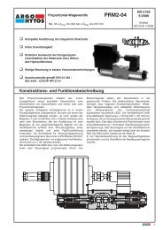
D e s c r i p t i o n<br />
Application area<br />
Ventilation of tanks for hydraulic and lubrication systems, and gearboxes.<br />
General<br />
The oil levels in the tanks of hydraulic systems are subject to continuous<br />
variation due to temperature changes and the operation of cylinders and<br />
pressure vessels.<br />
In order to prevent over pressure in the tanks, an exchange of air with<br />
the external atmosphere is necessary. By the use of a ventilating filter, the<br />
outside air that is drawn in is filtered and the ingress of dust is therefore<br />
prevented.<br />
Special features<br />
The ventilation openings are designed so that dust on the surface of the<br />
tank is not drawn in, and that the ingress of spray and rainwater is largely<br />
prevented.<br />
The use in marine applications presents no problem due to the use of<br />
synthetic materials and stainless steel.<br />
Design<br />
Flow direction bi-directional (air IN/OUT). The star-shaped pleating of the<br />
filter material results in:<br />
• large filter surfaces<br />
• low pressure drop<br />
• high dirt-holding capacities<br />
• long service life<br />
C h a ra c t e r i s t i c s<br />
Nominal flow rate<br />
Up to 225 gpm (see Selction Chart, column 2)<br />
The nominal flow rates indicated by ARGO-HYTOS are based on the<br />
following criteria:<br />
• Ventilating filters without double check valve:<br />
∆p < 0.44 psi<br />
• Ventilating filters with double check valve:<br />
∆p < 1.45 psi for air IN<br />
Connection<br />
Threaded ports according to American National Standard (ANSI).<br />
Sizes see Selection Chart, column 6 (other port threads on request)<br />
Filter fineness<br />
2 µm<br />
Tested in a single pass test with ISO MTD<br />
Hydraulic fluids<br />
Mineral oil and biodegradable fluids<br />
(HEES u. HETG, see info sheet 00.20)<br />
Ordering options / versions<br />
Integrated oil-level dipstick (for all types):<br />
A dipstick can be integrated in the ventilating filter for checking the oil<br />
level. Therefore, a separate dipstick or an additional opening in the tank is<br />
not required.<br />
Oil separator (<strong>L1.0406</strong>):<br />
An effective protection against splashing oil in mobile operation.<br />
Double check valves (L1.0506, L1.0807):<br />
By the use of double check valves, the exchange of air between the tank<br />
and the environment can be considerably reduced, whereby the ingress of<br />
dust is minimized and the lifetime of the air filter element can be increased.<br />
With the double check valve, an over-pressure can be created in the tank in<br />
order to improve the suction conditions for the pumps.<br />
A further advantage is the reduction of spray water entry and the loss of oil<br />
through the ventilating filter.<br />
Vandalism proof types:<br />
Ventilating filters in patented vandalism proof version, please see<br />
catalog sheet 50.20.<br />
Filling and ventilating filters in standard or patented vandalism proof<br />
version, see catalog sheet 50.30.<br />
Maintenance<br />
Ventilating filters should be changed at least every 1000 operating hours,<br />
or at minimum once a year.<br />
Operating temperature range<br />
- 22 °F ... + 212 °F (temporary - 40 °F ... + 248 °F)<br />
Materials<br />
Cap: Polyamide, GF reinforced<br />
(L1.0506 Polyester, GK reinforced)<br />
Base: Polyamide, GF reinforced<br />
(L1.0506 Polyester, GK filled)<br />
Dipstick: Stainless steel (1.4301)<br />
Gaskets: NBR (Viton on request)<br />
Filter media: Composite, multi-layer<br />
Mounting position<br />
No limitation, position on the tank see section Layout
D1<br />
D2<br />
D3<br />
Dx<br />
∆p [psi]<br />
∆p [psi]<br />
∆p [psi]<br />
Q [gpm]<br />
Q [gpm]<br />
Q [gpm]<br />
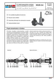
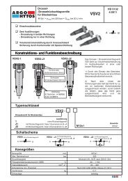
Filter fineness curves in Selection Chart, column 4<br />
Filtration ratio β for particles > x µm<br />
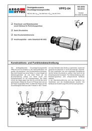
D i a g ra m s<br />
∆p-curves for complete filters in Selection Chart, column 2<br />
Pressure drop as a function of the flow volume<br />
Air IN/OUT<br />
Pressure drop as a function of the flow volume<br />
Air IN<br />
Pressure drop as a function of the flow volume<br />
Air IN<br />
Filtration ratio β as a function of particle size x tested in a single<br />
pass test with ISO MTD<br />
Particle size x [µm] (for particles larger<br />
than the given particle size x)<br />
Efficiency [%]<br />
Pressure drop as a function of the flow volume<br />
Air IN/OUT<br />
∆p [psi]<br />
∆p [psi]<br />
∆p [psi]<br />
Q [gpm]<br />
Pressure drop as a function of the flow volume<br />
Air OUT<br />
Q [gpm]<br />
Pressure drop as a function of the flow volume<br />
Air OUT<br />
Q [gpm]<br />
The abbreviations represent the following<br />
β-values resp. finenesses:<br />
2 CL = 2 µm Composite<br />
99.5 % efficiency for particles of size 2 µm<br />
tested in a single pass test with ISO MTD<br />
For special applications, finenesses differing from these curves<br />
are also available by using special composed filter media.<br />
183
gpm inch² psi psi inch inch inch lbs<br />
1 2 3 4 5 6 7 8 9 10 11 12 13 14<br />
<strong>L1.0406</strong>-43 32 D1/1 2 CL 5.4 ¼-18 NPTF - - - - - 1 0.06 -<br />
Remarks:<br />
• The ventilating filters listed in this chart are standard filters. If modifications are required, e.g., with integrated dipstick,<br />
we kindly ask for your request.<br />
• Ventilating filters in Vandalism Proof design see catalog sheet 50.20.<br />
* ∆p < 1.45 psi for air IN<br />
184<br />
S e l e c t i o n C h a r t<br />
Part No.<br />
Nominal flow rate<br />
Pressure drop see<br />
diagram D/curve no.<br />
Filter fineness see diagram Dx<br />
Filter surface<br />
Connection A<br />
Cracking pressure air IN<br />
Cracking pressure air OUT<br />
Dipstick measurement L1<br />
Dipstick measurement L2<br />
Dipstick measurement L3<br />
Symbol<br />
Weight<br />
L1.0506-47 40* D2/1 2 CL 5.4 1 1 /16-12 UN-2A -0.44 5.08 - - - 2 0.12 -<br />
<strong>L1.0706</strong>-04 65 D1/2 2 CL 7.8 1½-UNF-12 2A - - - - - 1 0.11 -<br />
L1.0807-16 170 D1/3 2 CL 31.5 ¾-14 NPT - - - - - 1 0.31 -<br />
L1.0807-57 145* D3/1 2 CL 31.5 ¾-14 NPT -0.44 5.08 - - - 2 0.35 -<br />
L1.0807-15 225 D1/4 2 CL 31.5 1 5 /8-12 UN-2A - - - - - 1 0.31 -<br />
L1.0807-56 145* D3/1 2 CL 31.5 1 5 /8-12 UN-2A -0.44 5.08 - - - 2 0.35 -<br />
Remarks
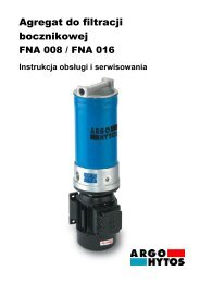
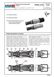
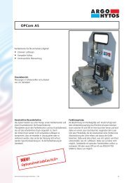
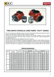
D i m e n s i o n s<br />
<strong>L1.0406</strong> L1.0506<br />
D<br />
D<br />
1 2<br />
C<br />
(eye R2.5 / hole ø0.08)<br />
Fixing chain<br />
(length 6.69 inch)<br />
on request<br />
ARGO-HYTOS<br />
Part No. S0.0512.1302<br />
M e a s u re m e n t s<br />
S y m b o l s<br />
G<br />
F<br />
E<br />
E<br />
G<br />
D<br />
C<br />
B<br />
F<br />
H<br />
L1.0807<br />
Version with UN thread<br />
H<br />
F<br />
G<br />
C<br />
E<br />
Type A 1 B C D E F G H<br />
<strong>L1.0406</strong> ¼-18 NPTF 2 1.24 0.71 1.46 1.52 0.30 0.49 -<br />
L1.0506 1 1 /16-12 UN-2A 1.42 0.95 1.81 1.52 0.32 0.98 0.70<br />
<strong>L1.0706</strong> 1½-UNF-12 2A 2.01 0.81 2.60 1.04 0.24 1.34 0.71<br />
L1.0807 1 5 /8-12 UN-2A 47 mm 1.50 3.15 1.97 0.31 0.83 0.55<br />
¾-14 NPT 2 33 mm as A 3.15 1.97 0.30 0.87 -<br />
1 The thread dimensions do not exactly conform to the ANSI standard thread (functioning with the ANSI standard thread is guaranteed)<br />
2 For NPT threads we recommend the use of gasket strip.<br />
<strong>L1.0706</strong><br />
L1.0807<br />
Version with NPT thread<br />
D<br />
B<br />
F<br />
G<br />
E<br />
185
186<br />
L a y o u t<br />
Sizes<br />
The determining factor for selecting the size is the maximum over / under<br />
pressure allowed in the container.<br />
For versions without double check valves, the initial pressure drop with a<br />
clean air filter should not exceed 0.44 psi.<br />
For versions with double check valves, the initial pressure drop for air IN<br />
with a clean air filter should not exceed 1.45 psi.<br />
Filter fineness<br />
In the ideal case, the fineness of the ventilating filter matches the fineness<br />
of the system filter (see also CETOP RP 98 H).<br />
By the use of filter fineness 2 CL the ingress of dust into the tank is<br />
effectively reduced.<br />
Mounting<br />
The ventilating filter should be mounted in a low-dust area of the machine<br />
and not in depressions in which water can collect.<br />
For mobile use, the ventilating filter is to be mounted on the tank such that<br />
neither splashing oil from the inside nor spray water from the outside can<br />
reach the area of the ventilation opening.<br />
Q u a l i t y A s s u ra n c e<br />
Quality management according to DIN EN ISO 9001<br />
To ensure constant quality in production and operation,<br />
ARGO-HYTOS filter elements undergo strict controls and tests<br />
according to the following DIN and ISO standards:<br />
DIN ISO 2941 Verification of collapse/burst resistance<br />
DIN ISO 2943 Verification of material compatibility with fluids<br />
DIN ISO 3724 Verification of flow fatigue characteristics<br />
Our engineers will be glad to assist you with questions concerning filter application, selection, and the cleanliness class of the filtered medium attainable<br />
under practical operating conditions.<br />
Illustrations may sometimes differ from the original. ARGO-HYTOS is not responsible for any unintentional mistake in this specification sheet.<br />
Double check valves<br />
By the use of double check valves, the exchange of air between the tank<br />
and the environment can be considerably reduced, whereby the ingress of<br />
dust is minimized and the lifetime of the air filter element is increased.<br />
With the double check valve, a predefined level of pressure can be created<br />
in the tank in order to improve the suction conditions for the pumps.<br />
The valve opening pressure required for the ventilating filter<br />
can be approximately determined with the ideal gas equation depending<br />
on the following system characteristics:<br />
• differential volume,<br />
• volume of oil in the system,<br />
• volume of air in the tank and the<br />
• operating temperatures.<br />
ISO 2942 Verification of fabrication integrity (Bubble Point Test)<br />
ISO 3968 Evaluation of pressure drop versus flow characteristics<br />
ISO 16889 Multi-Pass-Test (evaluation of filter fineness and<br />
dirt-holding capacity)<br />
Various quality controls during the production process guarantee the<br />
leakfree function and solidity of our filters.<br />
We produce fluid power solutions<br />
ARGO-HYTOS Inc. · P.O. Box 28 · Bowling Green, OH 43402 · USA<br />
Tel: +1-419-353-6070 · Fax: +1-419-354-3496 · info.us@argo-hytos.com · www.argo-hytos.com<br />
Subject to change<br />
9107187-us · 0206