Tutorial, AutoEditNC 4.0
Tutorial, AutoEditNC 4.0
Tutorial, AutoEditNC 4.0

You also want an ePaper? Increase the reach of your titles
YUMPU automatically turns print PDFs into web optimized ePapers that Google loves.
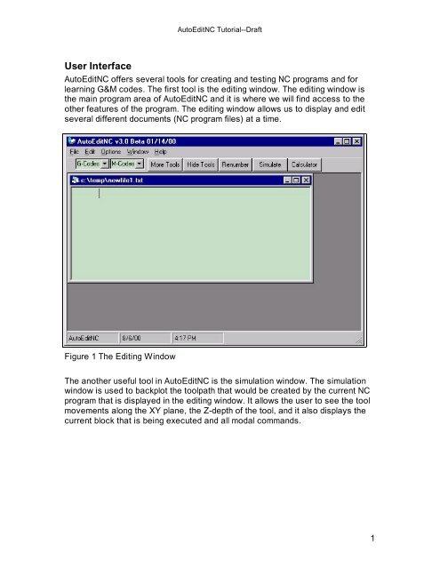
User Interface<br />
<strong>AutoEditNC</strong> <strong>Tutorial</strong>--Draft<br />
<strong>AutoEditNC</strong> offers several tools for creating and testing NC programs and for<br />
learning G&M codes. The first tool is the editing window. The editing window is<br />
the main program area of <strong>AutoEditNC</strong> and it is where we will find access to the<br />
other features of the program. The editing window allows us to display and edit<br />
several different documents (NC program files) at a time.<br />
Figure 1 The Editing Window<br />
The another useful tool in <strong>AutoEditNC</strong> is the simulation window. The simulation<br />
window is used to backplot the toolpath that would be created by the current NC<br />
program that is displayed in the editing window. It allows the user to see the tool<br />
movements along the XY plane, the Z-depth of the tool, and it also displays the<br />
current block that is being executed and all modal commands.<br />
1
Figure 2 The Simulation Window<br />
Quick Start<br />
<strong>AutoEditNC</strong> <strong>Tutorial</strong>--Draft<br />
This section will give you a quick overview of the processes involved in opening,<br />
creating, and testing a NC part program. We will start by opening a sample file<br />
and then we will backplot the file to verify its behavior.<br />
Open a Sample File<br />
We will start by going to the File menu and selecting Open. From here a dialog<br />
box will open and we will see a sample or tutorial folder depending on which<br />
version we are using. Browse either folder and then select a file.<br />
2
<strong>AutoEditNC</strong> <strong>Tutorial</strong>--Draft<br />
Figure 3 Program files can be opened, created, or saved from the File menu.<br />
In this case we will select a file named “tutorial one.txt” and then click on the<br />
Open button. This will cause the file to be opened and displayed in a document<br />
window from within the editing window. If you do not see this file, simply select<br />
any other .TXT file from the samples folder.<br />
The file is now ready to view or<br />
edit. You may have noticed<br />
that an empty document<br />
window is displayed when the<br />
program is first started. This<br />
window is used for creating a<br />
new program and it is not<br />
needed quite yet. We can<br />
close the window for now<br />
clicking on the close button (X)<br />
in the upper right of the<br />
window.<br />
Figure 4 The Open dialog box.<br />
3
<strong>AutoEditNC</strong> <strong>Tutorial</strong>--Draft<br />
Figure 5 The NC program as displayed in a document window. Many program<br />
files can be open simultaneously.<br />
Simulate the Toolpath<br />
The next step is to test the program to see if it works the way we had intended.<br />
Click on the Simulate button to launch the simulation module. The simulation<br />
will only read the active document that we have open in the editing window.<br />
Therefore, if multiple documents are open, then we have to make sure we click<br />
on the desired program to cause it to be the active window.<br />
4
<strong>AutoEditNC</strong> <strong>Tutorial</strong>--Draft<br />
Figure 6 The simulation window showing the finished backplot of the toolpath.<br />
The solid lines represent linear interpolation.<br />
Once the simulation window is open, we have to read the NC program into a<br />
buffer so that it can be simulated. This is accomplished by clicking on the Buffer<br />
button.<br />
Now that the program is loaded we can start the simulation by clicking the Start<br />
button. This will cause the simulation to execute one line at a time until the<br />
program has reached the end. The toolpath will be plotted in the graphics window<br />
to verify any tool movements in the XY plane and the Z-depth will be displayed in<br />
the Z-level area near the upper right of the window. We should also note that the<br />
tool outline and rapid motions are displayed as dashed lines, and that any<br />
interpolation is displayed as a solid line<br />
Creating a New File<br />
Now that we have seen how to open and test an existing file, let’s see how we<br />
can quickly create a new NC program. We will accomplish this by first opening a<br />
new (but empty) document and then by using several productivity tools to insert a<br />
program template and then inserting and editing individual blocks of code.<br />
We start a new program in the editing window by clicking on the File menu and<br />
then selecting New. This will place a blank document into the text area.<br />
5
<strong>AutoEditNC</strong> <strong>Tutorial</strong>--Draft<br />
Figure 7 Select New from the File menu to create a new file.<br />
Figure 8 The new file appears in the text window.<br />
Now that we have a blank document, we will insert a pre-made program template<br />
into the empty file. This will allow us to skip the trouble of typing the standard<br />
code that is found in all NC programs and let us concentrate on writing the<br />
unique code that cause the machine tool produce the desired motion.<br />
We accomplish this by first placing the mouse pointer over the empty document<br />
and then clicking on it. This will create an insertion point for the program<br />
template. Next, click on the Options menu and select Milling Template<br />
6
<strong>AutoEditNC</strong> <strong>Tutorial</strong>--Draft<br />
Standard. The text will be automatically pasted into the document starting at the<br />
insertion point.<br />
Figure 9 Click somewhere in the empty document and then insert a program<br />
template from the Options menu.<br />
7
<strong>AutoEditNC</strong> <strong>Tutorial</strong>--Draft<br />
Figure 10 The program template will be written into the new document. It is<br />
now ready to be modified to our needs.<br />
We are now at the point where we can start writing the code to make the<br />
workpiece. Of course, we have to have a great enough understanding of NC<br />
programming to know which codes to use.<br />
We can edit the program document manually just as we would with any other<br />
word processing program, or if you are unfamiliar with G&M-codes, then you can<br />
use the code creation tools to get started. The code creation tools can be<br />
accessed by clicking on the More Tools button. This will cause another toolbar<br />
to appear with buttons to add many different types of code.<br />
Again we must place the cursor at the insertion point before using the code<br />
creation tools. Use the mouse or the arrow keys to move the cursor to the line<br />
immediately below N30. Then use the delete key to erase lines N35-N50 and<br />
then hit the enter key to create a blank line or two. Now click on the Line button<br />
to open the linear interpolation window.<br />
The linear interpolation window gives an illustration of the code and a short<br />
explanation of its use. We can then click on the Add Code button to paste the<br />
code example into our document at the insertion point. We can then edit the code<br />
to our specific needs.<br />
8
<strong>AutoEditNC</strong> <strong>Tutorial</strong>--Draft<br />
Figure 11 Individual blocks of code can be typed manually into the program<br />
document or we can use the code creation tools. Simply place the cursor to<br />
the proper insertion point in the program document and then select the<br />
desired tool button. Click on the Add Code button to paste the code into the<br />
document.<br />
For this example, let’s place the following code between lines N30 and N97.<br />
N30 G00 Z.2<br />
G01 X1.0 Y0.0 F5.0<br />
G01 X1.0 Y1.0<br />
G01 X2.0 Y1.0<br />
N97 G91 G28 Z2.0<br />
When you have completed this, make sure that there are not any additional blank<br />
line or extra characters and then save the document by clicking on File and then<br />
Save. Also, we do not need to worry about adding any line numbers; the<br />
simulation will work fine without them. Your program should now look like the<br />
program in Figure 12.<br />
9
<strong>AutoEditNC</strong> <strong>Tutorial</strong>--Draft<br />
Figure 12 The program has been edited to include linear interpolation between<br />
lines N30 and N97.<br />
Next we can test the program in the simulation window. Click on Simulate in the<br />
editing window to launch the simulation module and next click Buffer and then<br />
Start to begin the backplot. If the backplot does not appear as in Figure 13, then<br />
you probably made a typographical error. If any changes are made to the<br />
program, you must save the file and buffer it again before the changes will<br />
appear in the simulation.<br />
10
<strong>AutoEditNC</strong> <strong>Tutorial</strong>--Draft<br />
Figure 13 The completed backplot of the NC program.<br />
11