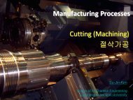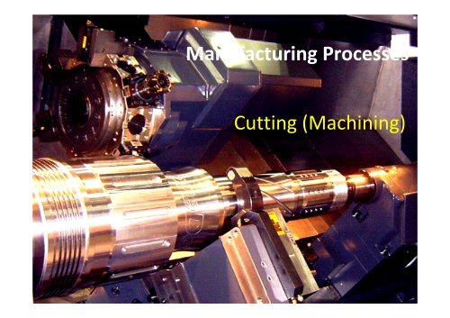
Manufacturing Processes Cutting (Machining)
Manufacturing Processes Cutting (Machining)
Manufacturing Processes Cutting (Machining)

Create successful ePaper yourself
Turn your PDF publications into a flip-book with our unique Google optimized e-Paper software.
<strong>Cutting</strong><br />
<strong>Manufacturing</strong> <strong>Processes</strong><br />
© 2011 Su-Jin Kim GNU<br />
<strong>Manufacturing</strong> <strong>Processes</strong><br />
<strong>Cutting</strong> (<strong>Machining</strong>)
<strong>Cutting</strong><br />
1. <strong>Cutting</strong> mechanics<br />
2. Tool wear<br />
3. Tool material<br />
4. Turning, Turning center<br />
5. Milling, <strong>Machining</strong> center<br />
<strong>Cutting</strong><br />
<strong>Manufacturing</strong> <strong>Processes</strong><br />
© 2011 Su-Jin Kim GNU
<strong>Cutting</strong> mechanics<br />
• Chip formation Shear break off<br />
• <strong>Cutting</strong> force = Specific energy x Area<br />
• Chatter (vibration)<br />
• <strong>Cutting</strong> temperature<br />
• Tool wear<br />
• Tool life equation<br />
<strong>Cutting</strong><br />
<strong>Manufacturing</strong> <strong>Processes</strong><br />
© 2011 Su-Jin Kim GNU
Mechanics of Chip Formation<br />
• Chips are produced by the shearing taking place along a<br />
shear plane.<br />
<strong>Cutting</strong><br />
<strong>Manufacturing</strong> <strong>Processes</strong><br />
© 2011 Su-Jin Kim GNU
<strong>Cutting</strong> Force (Theory)<br />
• According to maximum‐shear‐stress criterion, yielding<br />
occurs when the max shear stress within an element is<br />
equal to or exceeds a critical value (shear yield stress).<br />
Stock<br />
<strong>Cutting</strong><br />
<strong>Manufacturing</strong> <strong>Processes</strong><br />
© 2011 Su-Jin Kim GNU<br />
Tool<br />
σ 1<br />
(Assume no friction)<br />
Fc<br />
σ 1<br />
τ<br />
Mohr’s circle<br />
σ<br />
τ<br />
Ф<br />
Shear angle<br />
Shear plane
<strong>Cutting</strong> Force (Theory)<br />
<strong>Cutting</strong><br />
<strong>Manufacturing</strong> <strong>Processes</strong><br />
© 2011 Su-Jin Kim GNU<br />
w<br />
t 0<br />
• Shear Area = Width x Depth / sin (Shear Angle)<br />
t0<br />
As w<br />
sin<br />
t 0 /sin(φ)<br />
φ<br />
F s<br />
• Shear Force = Shear Stress * Shear Area<br />
wt0<br />
Fs A<br />
s <br />
sin<br />
Tool
<strong>Cutting</strong> Force (Theory)<br />
• Resultant force<br />
= Shear force / cos (shear angle + friction angle –rake angle)<br />
<strong>Cutting</strong><br />
<strong>Manufacturing</strong> <strong>Processes</strong><br />
© 2011 Su-Jin Kim GNU<br />
R<br />
<br />
cos<br />
F<br />
s<br />
<br />
wt<br />
sin<br />
cos<br />
0
<strong>Cutting</strong> Force (Theory)<br />
• <strong>Cutting</strong> force<br />
= Resultant force x cos (friction angle –rake angle)<br />
• Shear angle<br />
= pi/4 + rake angle/2 –friction angle/2<br />
<strong>Cutting</strong><br />
<strong>Manufacturing</strong> <strong>Processes</strong><br />
© 2011 Su-Jin Kim GNU<br />
F c<br />
R cos<br />
<br />
<br />
<br />
<br />
<br />
4 2 2
<strong>Cutting</strong> Force<br />
• Rake angle ↑ shear angle ↑, cutting force ↓ chip thickness ↓, cooler chip<br />
↓<br />
• Rake angle ↑ tool section ↓ strength at cutting edge ↓, heat conductivity<br />
↓<br />
• Relief angle ↑ friction ↓ tool life ↑, surface quality ↑<br />
• Relief angle ↑ strength at cutting edge ↓<br />
• Nose radius ↓ heat ↓, surface quality ↑<br />
• Force ↑< yield stress of stock ↑, cut depth ↑, cut width ↑<br />
<strong>Cutting</strong><br />
<strong>Manufacturing</strong> <strong>Processes</strong><br />
© 2011 Su-Jin Kim GNU<br />
Shear angle, φ<br />
Rake angle,α<br />
+<br />
Nose radius<br />
Relief angle,<br />
r
<strong>Cutting</strong> Force (Specific cutting energy)<br />
• <strong>Cutting</strong> force = Specific cutting energy x <strong>Cutting</strong> area<br />
Power c<br />
<strong>Cutting</strong><br />
<strong>Manufacturing</strong> <strong>Processes</strong><br />
© 2011 Su-Jin Kim GNU<br />
Fc ut<br />
Ac<br />
ut<br />
Tool<br />
Stock A c F c<br />
F V<br />
wt0<br />
Specific cutting energy (
Chip morphology<br />
• Type of chips produced<br />
influences surface finish<br />
and machining operation.<br />
1. Continuous chips<br />
Steel: http://www.youtube.com/watch?v=4bOzJiYAZD4<br />
Stainless: http://www.youtube.com/watch?v=DzAjpHFy4fw<br />
2. Built‐up‐edge chips<br />
3. Serrated chips<br />
4. Discontinuous chips<br />
Cast Iron: http://www.youtube.com/watch?v=RoooeTEEMxY&feature=related<br />
<strong>Cutting</strong><br />
<strong>Manufacturing</strong> <strong>Processes</strong><br />
© 2011 Su-Jin Kim GNU
Chip morphology<br />
Chip curl<br />
• Chip breaker shorter chip<br />
<strong>Cutting</strong><br />
<strong>Manufacturing</strong> <strong>Processes</strong><br />
© 2011 Su-Jin Kim GNU<br />
Groove Chip breaker
Chatter (Self‐excited vibration)<br />
• Chatter vibrating with high frequency noise is caused by<br />
interaction of chip‐removal process with flexibility of the<br />
tool.<br />
• It could be avoided by increasing dynamic stiffness and<br />
damping, by decreasing depth of cut and proper<br />
selection of spindle speed .<br />
<strong>Cutting</strong><br />
<strong>Manufacturing</strong> <strong>Processes</strong><br />
© 2011 Su-Jin Kim GNU<br />
Safe<br />
Chatter<br />
http://www.youtube.com/watch?v=uv3yUCl27wM
Temperature<br />
• <strong>Cutting</strong> power P=FV Heat Increase the<br />
temperature of chip, work piece, and tool<br />
<strong>Cutting</strong><br />
<strong>Manufacturing</strong> <strong>Processes</strong><br />
© 2011 Su-Jin Kim GNU
Tool wear<br />
• Mechanical wear<br />
1. Abrasive wear ‐ hardness<br />
2. Adhesive wear ‐ junction<br />
3. Fatigue wear ‐ crack<br />
• Thermo Chemical wear<br />
1. Diffusion wear (확산)<br />
2. Solution wear (용해)<br />
<strong>Cutting</strong><br />
<strong>Manufacturing</strong> <strong>Processes</strong><br />
© 2011 Su-Jin Kim GNU
Tool wear<br />
• The wear behaviour of cutting tools are flank<br />
wear(measure width of wear land), crater wear(at high<br />
speed, diffusion wear is the major reason, measure<br />
depth), nose wear, and chipping of the cutting edge.<br />
<strong>Cutting</strong><br />
<strong>Manufacturing</strong> <strong>Processes</strong><br />
© 2011 Su-Jin Kim GNU
Tool wear<br />
<strong>Cutting</strong><br />
<strong>Manufacturing</strong> <strong>Processes</strong><br />
© 2011 Su-Jin Kim GNU
Tool life (F.W. Taylor)<br />
• Tool‐wear relationship for cutting various steels is<br />
<strong>Cutting</strong><br />
<strong>Manufacturing</strong> <strong>Processes</strong><br />
© 2011 Su-Jin Kim GNU<br />
VT n <br />
C<br />
V = cutting speed<br />
T = time (min)<br />
C = constant.<br />
n = exponent depends on cutting conditions<br />
HSS 0.14-0.16, Uncoated carbides 0.21-0.25, TiC insert 0.30,<br />
Polydiamond 0.33, TiN insert 0.35, Ceramic coated insert 0.40
Tool life curve<br />
• Tool‐life is effected by depth and feed rate.<br />
VT<br />
• Tool wear is also depend on<br />
tool and workpiece material<br />
<strong>Cutting</strong><br />
<strong>Manufacturing</strong> <strong>Processes</strong><br />
© 2011 Su-Jin Kim GNU<br />
n<br />
d<br />
x<br />
f<br />
y<br />
<br />
C<br />
d = depth of cut<br />
f = feed rate (in mm/rev) in turning
Ex<br />
Increasing tool life by reducing the cutting speed<br />
Given that n=0.5 and VT n =C, if the V reduced 50%, calculate the<br />
increase of tool life.<br />
Solution<br />
VT 0.5 =C (1)<br />
0.5VT 2 0.5 =C (2)<br />
(2)/(1)<br />
0.5(T 2/ T) 0.5 =1<br />
T 2 =4T<br />
Increase tool life 4 times.<br />
<strong>Cutting</strong><br />
<strong>Manufacturing</strong> <strong>Processes</strong><br />
© 2011 Su-Jin Kim GNU
Surface Finish and Surface Integrity<br />
Feed marks<br />
• In turning, peak‐to‐valley roughness is<br />
<strong>Cutting</strong><br />
<strong>Manufacturing</strong> <strong>Processes</strong><br />
© 2011 Su-Jin Kim GNU<br />
Stock<br />
R<br />
t<br />
<br />
2<br />
fr<br />
8R<br />
R<br />
Tool<br />
f r = feed per revolution<br />
R = nose radius<br />
f<br />
R t
<strong>Cutting</strong> Tool Materials<br />
• HSS<br />
• Carbide<br />
• Ceramic<br />
• Diamond<br />
• CBN<br />
<strong>Cutting</strong><br />
<strong>Manufacturing</strong> <strong>Processes</strong><br />
© 2011 Su-Jin Kim GNU
<strong>Cutting</strong>‐Tool Materials<br />
• A cutting tool has the following characteristics:<br />
1. Hardness<br />
2. Toughness<br />
3. Wear resistance<br />
4. Chemical stability<br />
<strong>Cutting</strong><br />
<strong>Manufacturing</strong> <strong>Processes</strong><br />
© 2011 Su-Jin Kim GNU
HSS<br />
HSS (High‐speed steels)<br />
• HSS cuts faster than carbon tool steel, hence the name<br />
high speed steel, but slower than carbide tools.<br />
• It is often used in power saw blades and drill bits.<br />
TiN‐Coated HSS<br />
• PVD (physical vapor deposition), TiN coating reduces<br />
tool wear.<br />
HSS Drill: http://www.youtube.com/watch?v=98DvSQNHLMU<br />
<strong>Cutting</strong><br />
<strong>Manufacturing</strong> <strong>Processes</strong><br />
© 2011 Su-Jin Kim GNU
Carbides<br />
Carbides (초경)<br />
• Better wear resistance, stiffness, hot hardness<br />
• Tungsten carbide: WC + Co(for toughness) powder<br />
metallurgy (sintered), suitable for non‐ferrous, grey cast<br />
iron<br />
• Titanium carbide: TiC + Co : TiC is suitable for steel and<br />
cast iron<br />
Coated Carbide<br />
• Carbide + TiC, TiN, Al 2O 3 coated<br />
by CVD (chemical vapor deposition)<br />
• Chemically stable greatly reduce crater wear<br />
<strong>Cutting</strong><br />
<strong>Manufacturing</strong> <strong>Processes</strong><br />
© 2011 Su-Jin Kim GNU
Cermets<br />
Ceramics<br />
Aluminum oxide(Al 2O 3), Silicon‐nitride(SiN), cold pressed and<br />
hot sintered<br />
Hot hardness ↑, toughness ↓ (chipping), thermal shock<br />
Cermets<br />
Ceramic(Al 2O 3) + metal binder(TiC)<br />
Hot hardness ↑, toughness ↓, thermal expansion ↑<br />
http://www.youtube.com/watch?v=Om9gzgNPf80<br />
Insert: less thermal stress, eliminate grinding by user, less<br />
setting time<br />
<strong>Cutting</strong><br />
<strong>Manufacturing</strong> <strong>Processes</strong><br />
© 2011 Su-Jin Kim GNU
Diamond, CBN<br />
Diamond (Poly crystal diamond)<br />
• Hardest material, Not good for steel<br />
http://www.youtube.com/watch?v=vAvfrrlMZg4<br />
CBN (polycrystalline cubic boron nitride)<br />
• 2nd hardest material, brittle, expensive<br />
http://www.youtube.com/watch?v=mKxX50OMBd4&p=9B6D9EAE75875D9D<br />
<strong>Cutting</strong><br />
<strong>Manufacturing</strong> <strong>Processes</strong><br />
© 2011 Su-Jin Kim GNU
Tool materials<br />
Tool materials, feeds, and cutting speeds<br />
• Characteristics of cutting‐tool materials gives a range of<br />
cutting speeds and feeds for different applications.<br />
<strong>Cutting</strong><br />
<strong>Manufacturing</strong> <strong>Processes</strong><br />
© 2011 Su-Jin Kim GNU
Workpiece materials<br />
Workpiece materials and cutting speeds<br />
<strong>Cutting</strong><br />
<strong>Manufacturing</strong> <strong>Processes</strong><br />
© 2011 Su-Jin Kim GNU
<strong>Cutting</strong> Tool Makers<br />
• www.taegutec.co.kr<br />
• www.yg1.co.kr<br />
<strong>Cutting</strong><br />
<strong>Manufacturing</strong> <strong>Processes</strong><br />
© 2011 Su-Jin Kim GNU
<strong>Cutting</strong> Fluids<br />
• Also called lubricants and coolants, cutting fluids.<br />
• Used extensively in machining operations to:<br />
1. Cool the cutting zone<br />
2. Reduce friction and wear<br />
3. Reduce forces and energy consumption<br />
4. Wash away chips<br />
5. Protect surfaces from any environmental attack<br />
<strong>Cutting</strong><br />
<strong>Manufacturing</strong> <strong>Processes</strong><br />
© 2011 Su-Jin Kim GNU
Turning<br />
• A piece of material is rotated and a single point cutting<br />
tool is traversed along 2 axes of motion to produce the<br />
cylinder, tubular components and various rotational<br />
geometries.<br />
<strong>Cutting</strong><br />
<strong>Manufacturing</strong> <strong>Processes</strong><br />
© 2011 Su-Jin Kim GNU
Lathe<br />
• Turning can be done manually, in a traditional form of<br />
lathe, which frequently requires continuous supervision<br />
by the operator.<br />
<strong>Cutting</strong><br />
<strong>Manufacturing</strong> <strong>Processes</strong><br />
© 2011 Su-Jin Kim GNU
Turning center (CNC Lathe)<br />
• Turning can be done by using a computer numerical<br />
control, known as CNC.<br />
<strong>Cutting</strong><br />
<strong>Manufacturing</strong> <strong>Processes</strong><br />
© 2011 Su-Jin Kim GNU
Turning process<br />
• Straight turning<br />
• Taper turning<br />
• Profiling (Couture turning)<br />
• External grooving<br />
http://www.youtube.com/watch?v=tDc0l9Gm8D4<br />
<strong>Cutting</strong><br />
<strong>Manufacturing</strong> <strong>Processes</strong><br />
© 2011 Su-Jin Kim GNU<br />
http://www.youtube.com/watch?v=5AB_etoHesI&p=9B6D9EAE75875D9D
Math for Turning<br />
• <strong>Cutting</strong> speed(mm/min) = 3.14 x Diameter x Spindle<br />
<strong>Cutting</strong><br />
<strong>Manufacturing</strong> <strong>Processes</strong><br />
© 2011 Su-Jin Kim GNU<br />
V = π D S<br />
• MRR (Material Removal Rate) = Volume / Time = 3.14 x<br />
Diameter x Depth x Feed per revolution x Spindle<br />
D<br />
df S<br />
MMR avg r<br />
• <strong>Cutting</strong> time = Distance / (Feed per revolution x Spindle)<br />
V<br />
S<br />
t<br />
<br />
l<br />
f S<br />
r<br />
S
TurnMill<br />
• Turning center has additional<br />
milling axis is called TurmMill<br />
(복합기)<br />
<strong>Cutting</strong><br />
<strong>Manufacturing</strong> <strong>Processes</strong><br />
© 2011 Su-Jin Kim GNU<br />
http://ma.gnu.ac.kr/vod/machining/TurnMill.AVI
Milling<br />
• <strong>Cutting</strong> tool is rotated and traversed along 3 axes of<br />
motion to produce from simple rectangular plane, slot,<br />
hole and complex contour.<br />
<strong>Cutting</strong><br />
<strong>Manufacturing</strong> <strong>Processes</strong><br />
© 2011 Su-Jin Kim GNU
Milling<br />
<strong>Cutting</strong><br />
<strong>Manufacturing</strong> <strong>Processes</strong><br />
© 2011 Su-Jin Kim GNU
<strong>Machining</strong> center (CNC Milling)<br />
C Type<br />
<strong>Cutting</strong><br />
<strong>Manufacturing</strong> <strong>Processes</strong><br />
© 2011 Su-Jin Kim GNU<br />
Horizontal M/C<br />
Bridge Type<br />
Vertical M/C<br />
http://www.youtube.com/user/GlacernMachineTools<br />
5AX M/C
Automatic Tool Changer (ATC)<br />
<strong>Cutting</strong><br />
<strong>Manufacturing</strong> <strong>Processes</strong><br />
© 2011 Su-Jin Kim GNU<br />
Changer Arm<br />
Tool<br />
Spindle
Automatic Pallet Changer (APC)<br />
Pallet #1<br />
<strong>Cutting</strong><br />
<strong>Manufacturing</strong> <strong>Processes</strong><br />
© 2011 Su-Jin Kim GNU<br />
Pallet #2
Work holding Vise, Clamp<br />
• Work is fixed by vise or clamp on the table with T‐slot<br />
<strong>Cutting</strong><br />
<strong>Manufacturing</strong> <strong>Processes</strong><br />
© 2011 Su-Jin Kim GNU<br />
http://www.youtube.com/user/GlacernMachineTools#p/u/5/J1VtofzVG24<br />
Flex clamp: http://ma.gnu.ac.kr/vod/<strong>Machining</strong>/Clamp.MP4
Tool holder, Tools<br />
Holder + Collet + Solid Endmill Insert Endmill<br />
http://www.youtube.com/watch?v=IPWGV_EGAHw&feature=related<br />
<strong>Cutting</strong><br />
<strong>Manufacturing</strong> <strong>Processes</strong><br />
© 2011 Su-Jin Kim GNU
Tool holder, Tools<br />
<strong>Cutting</strong><br />
<strong>Manufacturing</strong> <strong>Processes</strong><br />
© 2011 Su-Jin Kim GNU
Milling operations<br />
• Face cutter<br />
• Endmill : Flat, Ball, Rounded<br />
Face Cutter<br />
Basic: http://www.youtube.com/watch?v=j0vRYe9uvnI<br />
Face: http://www.youtube.com/watch?v=9OsNUi_o6C4<br />
<strong>Cutting</strong><br />
<strong>Manufacturing</strong> <strong>Processes</strong><br />
© 2011 Su-Jin Kim GNU<br />
Flat endmill (Slotting)<br />
Endmill: http://www.youtube.com/user/GlacernMachineTools#p/u/1/HfIaISnqHOk
Math for milling<br />
• <strong>Cutting</strong> speed(mm/min) = 3.14 x Diameter x Spindle<br />
<strong>Cutting</strong><br />
<strong>Manufacturing</strong> <strong>Processes</strong><br />
© 2011 Su-Jin Kim GNU<br />
V = π D S<br />
• Feed per tooth = Feed / (Spindle x Number of teeth)<br />
F / Sn<br />
<br />
• MMR = Depth x Width x Feed<br />
MRR = d w F<br />
f t<br />
f t<br />
F (mm/min)<br />
w<br />
d
Huge 3+2 axis Milling<br />
• Has additional rotation BC axis on<br />
head.<br />
• Used for automobile door panel and<br />
bumper mold.<br />
http://ma.gnu.ac.kr/vod/machining/Huge_machine_tools.AVI<br />
<strong>Cutting</strong><br />
<strong>Manufacturing</strong> <strong>Processes</strong><br />
© 2011 Su-Jin Kim GNU<br />
http://ma.gnu.ac.kr/vod/machining/Huge_5axis.AVI
5‐axis machining<br />
• Has 2 tinting A C or B C axis on table or head.<br />
Rotary table: http://ma.gnu.ac.kr/vod/<strong>Machining</strong>/Rotaty_table.MP4<br />
<strong>Cutting</strong><br />
<strong>Manufacturing</strong> <strong>Processes</strong><br />
© 2011 Su-Jin Kim GNU<br />
Impeller : http://ma.gnu.ac.kr/vod/<strong>Machining</strong>/5axis_machining_impeller.MP4
Drilling<br />
• Drills produces deep holes.<br />
<strong>Cutting</strong><br />
<strong>Manufacturing</strong> <strong>Processes</strong><br />
© 2011 Su-Jin Kim GNU<br />
Drill<br />
Drilling machine<br />
Insert drill<br />
Max drill<br />
Drill: http://www.youtube.com/watch?v=ul20R32HJ3E<br />
Drill: http://ma.gnu.ac.kr/vod/<strong>Machining</strong>/Drill.MP4
Tapping<br />
• Tap produces thread inside the hold.<br />
• Tap Feed Rate = RPM x Pitch<br />
Ex) M6 x 1 at 2000 RPM = 2000 mm/min<br />
<strong>Cutting</strong><br />
<strong>Manufacturing</strong> <strong>Processes</strong><br />
© 2011 Su-Jin Kim GNU<br />
Tapping Tapping holder and tool<br />
http://www.youtube.com/watch?v=vCHQLFZHHJc
Reaming, Boring<br />
• Reamer enlarges an hole to the diameter of the tool.<br />
• Boring produce precise circular internal profiles.<br />
<strong>Cutting</strong><br />
<strong>Manufacturing</strong> <strong>Processes</strong><br />
© 2011 Su-Jin Kim GNU<br />
Reaming<br />
Boring<br />
Drilling, Tapping, Boring: http://vimeo.com/8642433<br />
http://www.youtube.com/user/GlacernMachineTools#p/u/0/om6GQKfoS1g
Planer and Shaper<br />
<strong>Cutting</strong><br />
<strong>Manufacturing</strong> <strong>Processes</strong><br />
© 2011 Su-Jin Kim GNU
Broaching<br />
• Linear broaching: the broach is run linearly against a<br />
surface of the workpiece to effect the cut.<br />
• Rotary broaching: the broach is rotated and pressed into<br />
the workpiece to cut an axis symmetric shape.<br />
Broaching gear<br />
http://www.youtube.com/watch?v=2K45B6tDqsg&p=9B6D9EAE75875D9D<br />
<strong>Cutting</strong><br />
<strong>Manufacturing</strong> <strong>Processes</strong><br />
© 2011 Su-Jin Kim GNU<br />
Rotary broaching:<br />
http://www.youtube.com/watch?v=gUEcagEmmZo&p=9B6D9EAE75875D9D
Sawing and saws<br />
• A cutting operation where the tool consists of a series<br />
of small teeth that removes material.<br />
<strong>Cutting</strong><br />
<strong>Manufacturing</strong> <strong>Processes</strong><br />
© 2011 Su-Jin Kim GNU<br />
Disk saw<br />
Belt saw
Gear Hobbing<br />
• A hob (cutter) is rotated one revolution to transfer each<br />
tooth profile onto a rotating gear blank.<br />
• Used very often for medium to high sizes of production<br />
runs.<br />
<strong>Cutting</strong><br />
<strong>Manufacturing</strong> <strong>Processes</strong><br />
© 2011 Su-Jin Kim GNU<br />
http://www.youtube.com/watch?v=DwFssm9trSc
Design for <strong>Machining</strong><br />
• Geometric compatibility<br />
• Dimensional compatibility<br />
1. Availability of tools<br />
2. Drill dimensions, aspect ratio<br />
• Constraints<br />
1. Process physics<br />
2. Deep pocket<br />
3. <strong>Machining</strong> on inclined faces<br />
• Set up and fixturing<br />
1. Tolerancing is $$$<br />
2. Minimize setups<br />
<strong>Cutting</strong><br />
<strong>Manufacturing</strong> <strong>Processes</strong><br />
© 2011 Su-Jin Kim GNU
Economics of <strong>Machining</strong><br />
Total cost per piece consists of four items:<br />
C<br />
m<br />
C<br />
C<br />
<strong>Cutting</strong><br />
<strong>Manufacturing</strong> <strong>Processes</strong><br />
© 2011 Su-Jin Kim GNU<br />
s<br />
l<br />
t<br />
p<br />
where<br />
C<br />
C<br />
C<br />
C<br />
C<br />
p<br />
m<br />
C<br />
cost per piece<br />
s<br />
l<br />
C<br />
t<br />
machining cost<br />
cost of setting up for machining<br />
cost of loading, unloading and machine handling<br />
tooling cost
Example 8.4<br />
Material‐removal rate and cutting force in turning<br />
A 15.24-cm-long, 1.27-cm-diameter 304 stainless-steel rod is being reduced in<br />
diameter to 1.2192 cm by turning on a lathe. The spindle rotates at N=4000 rpm<br />
and the tool is travelling at an axial speed of 20.32 cm/min. Calculate the cutting<br />
speed, material-removal rate, cutting time, power dissipated, and cutting force.<br />
Solution<br />
Maximum cutting speed is<br />
<strong>Cutting</strong> speed at machined diameter is<br />
Depth of cut and feed is<br />
<strong>Cutting</strong><br />
<strong>Manufacturing</strong> <strong>Processes</strong><br />
© 2011 Su-Jin Kim GNU<br />
V<br />
D N <br />
1.<br />
27 1.<br />
219<br />
20.<br />
32<br />
d<br />
0.<br />
0255 cm and f <br />
2<br />
400<br />
0<br />
1. 27400<br />
15.<br />
959 m/min<br />
V<br />
1. 2192400<br />
15.<br />
321m/min<br />
<br />
0.<br />
0508<br />
cm/rev
Example 8.4<br />
Material‐removal rate and cutting force in turning<br />
Solution<br />
Material-removal rate is<br />
MMR <br />
The torque and cutting force is<br />
<strong>Cutting</strong><br />
<strong>Manufacturing</strong> <strong>Processes</strong><br />
© 2011 Su-Jin Kim GNU<br />
3<br />
1. 24450.<br />
02550.<br />
0508400<br />
2.<br />
02586 cm / min<br />
15.<br />
24<br />
Actual time taken to cut is t <br />
0.<br />
75 min<br />
0. 0508400<br />
Amount of power dissipated is<br />
3 410 Power 2. 02586<br />
135<br />
W<br />
82597<br />
T 32.<br />
8643 kg - cm and Fc<br />
<br />
4002 60<br />
32. 86432<br />
1. 2445<br />
<br />
52.<br />
8153<br />
kg
References: Machine Tool Makers<br />
• www.doosaninfracore.co.kr<br />
• www.wia.co.kr<br />
• www.hwacheon.co.kr<br />
• www.mazak.jp (Japan)<br />
• www.haascnc.com (USA)<br />
• www.deckelmaho.com (EU)<br />
<strong>Cutting</strong><br />
<strong>Manufacturing</strong> <strong>Processes</strong><br />
© 2011 Su-Jin Kim GNU