2000/3000 Ergo Express Carts - Clinical Engineering
2000/3000 Ergo Express Carts - Clinical Engineering 2000/3000 Ergo Express Carts - Clinical Engineering
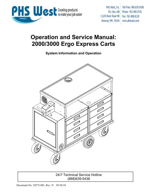
Operation and Service Manual: 2000/3000 Ergo Express Carts Document No. 54572-001, Rev. N 05/26/10 System Information and Operation 24/7 Technical Service Hotline (888)639-5438
- Page 2 and 3: Introduction Document No. 54572-001
- Page 4 and 5: Basic Operation Document No. 54572-
- Page 6 and 7: lamp (see reverse button). Both lev
- Page 8 and 9: Fault Code Example: Two flashes fol
- Page 10 and 11: Document No. 54572-001, Rev. N 05/2
Operation and Service Manual:<br />
<strong>2000</strong>/<strong>3000</strong> <strong>Ergo</strong> <strong>Express</strong> <strong>Carts</strong><br />
Document No. 54572-001, Rev. N 05/26/10<br />
System Information and Operation<br />
24/7 Technical Service Hotline<br />
(888)639-5438
Introduction<br />
Document No. 54572-001, Rev. N 05/26/10<br />
Table of Contents<br />
Introduction………………………………… 2<br />
Safety………………………………...…….. 3<br />
Daily Inspection………………………...….. 3<br />
Basic Operation………………………...…... 4<br />
User Interface Details……………...…….. 5<br />
Safety and Operational Features……..…….. 6<br />
Troubleshooting……………………..…….. 7<br />
U.I. Programming…………………..……… 7<br />
Wiring Diagram…………………..……..…. 10<br />
Parts Diagram……………………..….……. 11<br />
Parts List………………………….......……. 11<br />
Warranty……………………………...……. 12<br />
Your <strong>2000</strong>/<strong>3000</strong> Cart is a electrically powered vehicle that can accommodate a variety of<br />
equipment. For an understanding of efficient and safe operation of the cart, it is important<br />
that you read this manual.<br />
This <strong>Ergo</strong> <strong>Express</strong> powered cart uses a microprocessor based controller to operate all<br />
functions, including drive speed, drive direction, a motor speed governor, a battery<br />
charge meter, and an automatic motor brake. Additionally the microprocessor controls<br />
many functions that may not be readily apparent to a user, such as load compensation,<br />
acceleration control, emergency stop behavior, and motor current limiting.<br />
If you have any questions, call PHS West, 24/7 at (888)639-5438<br />
2
Document No. 54572-001, Rev. N 05/26/10<br />
Safety<br />
• Before servicing disconnect the power at the batteries, and unplug the chargers.<br />
• All batteries are sealed, and maintenance free. Do not open the batteries.<br />
• Never operate the cart if your visibility is obstructed.<br />
• Always use safety straps while towing other equipment.<br />
• Use caution when operating the cart on steep inclines.<br />
• Never carry riders on the cart.<br />
• Use the motion alarm in congested areas.<br />
• Never leave the cart unattended while the parking brake is disengaged.<br />
• Turn the power off when leaving the cart unattended.<br />
Daily Inspection<br />
Include the following checks in a daily inspection:<br />
a) Visually check the caster wheels for damage.<br />
b) Check the battery charge indicator. Operating the cart with a very low charge can<br />
damage the batteries.<br />
c) If equipped with safety straps, check that they are functioning and secure.<br />
d) Ensure that the power cord is secured in the electrical cabinet.<br />
e) Check the emergency stop switch for operation.<br />
f) Visually check the cart for any other external damage.<br />
g) Visually check the power cord and plug to monitor normal wear and tear. If the cord or<br />
plug is found to have damage from normal wear and tear. Remove from service and<br />
replace immediately per your normal protocol.<br />
3
Basic Operation<br />
Document No. 54572-001, Rev. N 05/26/10<br />
Figure 1 – Electrical Cabinet Interior<br />
1. Turn the key counter clockwise to the on position. Check the battery level indicator to<br />
verify the batteries have an adequate charge. Check the reverse indicator to determine the<br />
direction the cart will travel when the throttle is engaged.<br />
2. Slowly engage the throttle lever (either side, but not both) until the cart begins to move.<br />
Position yourself behind the UI with both hands on the handle grips. Use the fingers from<br />
one hand to operate the throttle.<br />
The two throttle levers on the user interface are used to control the speed of the drive motor. When either is<br />
engaged, the cart will move in the direction determined by the reverse indicator lamp. Both levers perform the<br />
same, functioning as proportional speed controls. Engaging the throttle fully gives full speed. Engaging it halfway<br />
results in half speed, ect.<br />
3. The blue mushroom switch on the front of the user interface is an emergency stop switch.<br />
When activated the cart will immediately stop. The cart will not operate if this switch is<br />
4
held closed.<br />
4. The motion alarm button toggles the audible motion alarm. When set to the ‘on’ position,<br />
the control will beep while the cart is in motion. The indicator lamp next to the horn button<br />
is illuminated when the warning horn is on.<br />
User Interface Details<br />
Document No. 54572-001, Rev. N 05/26/10<br />
Figure 2 – The <strong>Ergo</strong> <strong>Express</strong> User Interface<br />
Key switch<br />
The ON/OFF key-switch located on the side of the UI acts as the main power switch.<br />
Turning the key-switch from OFF (O) to ON (I) causes microprocessor to initialize. If<br />
the cart is left unattended for several minutes, the microprocessor will enter sleep mode<br />
and power itself off. To exit sleep mode, toggle the key-switch to the off position, then<br />
to on.<br />
Throttle Lever<br />
The two throttle levers on the user interface are used to control the speed of the drive motor.<br />
When one is engaged, the cart will move in the direction determined by the reverse indicator<br />
5
lamp (see reverse button). Both levers perform exactly the same function.<br />
Reverse Button<br />
The Reverse button acts as a direction toggle, allowing a user to operate the cart in<br />
either the forward or reverse direction. If the reverse lamp is illuminated, the cart will<br />
travel in the reverse direction. The reverse direction is to your back when you are<br />
facing the UI with both hands on the handle grips.<br />
Speed Selector Pushbuttons<br />
The speed selector buttons act as a speed governor. The speed setting determines the<br />
top speed of the cart when the throttle is fully engaged. If you feel that the cart’s full<br />
speed velocity is too fast, you can reduce it by adjusting the speed buttons. The speed<br />
indicator ladder is positioned next to the speed control buttons, and displays speed<br />
governor setting.<br />
Motion Alarm Pushbutton<br />
The motion alarm is a beep that will sound while the cart is in motion. The button with<br />
the ‘horn’ symbol is used to toggle the alarm on and off. An indicator lamp is<br />
illuminated when this feature is activated. When the cart is initially powered on, the<br />
motion alarm is toggled on by default.<br />
Battery Charge Level display<br />
The battery level indicator on the UI indicates the level of charge on the cart’s batteries.<br />
When all the indicator bars are illuminated, the battery is fully charged. When only one<br />
bar is illuminated, the battery charge is very low. The display will start flashing when the<br />
charge is critically low. Operating the cart when the batteries are low can damage the<br />
batteries.<br />
Blue Stop Button<br />
The blue mushroom switch is an emergency stop switch. When activated, the cart will<br />
immediately stop. The cart will not operate if this button is held closed.<br />
Safety and Operation Features<br />
The UI is equipped with a number of internal features to enhance the operation of the<br />
system.<br />
• Throttle Engaged during Power Up: To prevent abrupt startups, the cart will not<br />
operate if the throttle is depressed while the key-switch is turned on. The throttle must<br />
be in the neutral position when the control is turned on.<br />
• Sleep Mode: The control system utilizes a power saving mode designed to conserve<br />
battery life. If the system does not detect user input for several minutes, the controller<br />
will power itself off. To exit sleep mode, turn the key switch to the off position, and then<br />
to on.<br />
Parking Brake: The cart automatically engages a motor brake when the drive wheels<br />
are not being powered, even while the system power is off. If the cart must be moved<br />
manually (by pushing for example), the motor brake must be physically disengaged.<br />
Refer to figure 2 for the over-ride lever location. While the brake is physically<br />
disengaged, the cart will not operate, and a fault code will flash on the UI.<br />
Document No. 54572-001, Rev. N 05/26/10<br />
6
Document No. 54572-001, Rev. N 05/26/10<br />
Figure 3 – Brake disengagement lever position<br />
Throttle lock-out during charging: If the system is charging, the throttle levers will be<br />
disabled. If the throttles are engaged while charging a fault code will be displayed on<br />
the UI.<br />
Anti Runaway If for any reason, the parking brake lever is released, and the cart rolls<br />
away, the controller will automatically limit the speed of the cart. This function operates<br />
even if the cart is powered off.<br />
Start Compensation – The controller will sense when the cart is stopped on an inclined<br />
surface, and provide additional power when started to prevent roll back.<br />
Troubleshooting<br />
In its power on sequence, the control will perform a self diagnostic check, and report<br />
fault codes if any are detected. The codes are flashed in the battery charge display,<br />
and can be interpreted using the table below. There are three states provided by the<br />
battery charge display. These are...<br />
Steady ON - Indicates “normal” status and will glow steady during most operations.<br />
Steady OFF - Indicates Power is off. There is no battery power.<br />
Flashing – The display will flash an error code. See the table below.<br />
Error Codes<br />
In regular operation with no faults present, the battery charge display will be illuminated<br />
steadily. If during operation the controller detects a fault, the display will flash a code to<br />
indicate the type of fault. The display will flash the first number of the code, pause for<br />
approximately one second, and then flash the second part of the code. Count the<br />
flashes to determine the fault code. The controller will continually repeat the flash code<br />
until powered off.<br />
7
Fault Code Example: Two flashes followed by a pause, and then two more flashes<br />
indicates a fault code 2-2 "Motor Open" condition (see the fault code table).<br />
When a fault is corrected, the controller must be reset by turning the key-switch to the off<br />
position, and then back to the on position. If the display continues to flash, either the fault<br />
has not been corrected, or another problem exists. See the fault code table for more<br />
information on faults.<br />
Table 1 - Fault Codes<br />
Error<br />
Code<br />
Document No. 54572-001, Rev. N 05/26/10<br />
Problem Possible Causes<br />
1-1 Brake Short Shorted brake, loose/broken<br />
connection to brake, faulty U.I<br />
module<br />
1-2 Brake Open Brake shorted to case,<br />
missing/open brake, loose/broken<br />
connection to brake, faulty U.I.<br />
module<br />
2-1 Motor Short Defective motor, loose/broken<br />
connection to motor, faulty U.I.<br />
module<br />
2-2 Motor Open Defective motor, loose/broken<br />
connection to motor, brake<br />
manually released, faulty U.I.<br />
module<br />
2-3 Power Relay<br />
Defective batteries, faulty U.I.<br />
Short<br />
2-4 PSL Motor<br />
Short<br />
4-2 Charge Mode<br />
Time Out<br />
5-3 Throttle Failband<br />
module<br />
PSL Motor, loose/broken<br />
connection to PSL motor, faulty<br />
U.I. module<br />
Bad charger cable, bad batteries,<br />
bad charger<br />
Throttle control pot is off<br />
center/open, loose/broken<br />
connection/cable, faulty U.I.<br />
module<br />
U.I Module Programmability via a hand-held Programmer<br />
Certain parameters (such as acceleration and deceleration rates) can be changed with the<br />
use of a hand-held programmer. If you are unhappy with certain controller behavior, contact<br />
PHS West to discuss adjustments. Our technicians can send you a programmer, and guide<br />
you through reprogramming the control. Examples of parameters that can be adjusted<br />
include…<br />
• Forward speed maximum<br />
• Reverse speed maximum<br />
• Forward acceleration rate<br />
• Forward deceleration rate<br />
• Reverse acceleration rate<br />
The UI display will briefly flash when the power is turned on. This is<br />
normal, and does not indicate a fault.<br />
The UI display will flash to indicate a full charge while the batteries are<br />
being charged. This does not indicate a fault.<br />
8
• Reverse deceleration rate<br />
• Time required to activate sleep mode<br />
• Throttle release deceleration (completely releasing the throttle vs. incrementally varying the<br />
throttle)<br />
• Brake onset delay<br />
• Low battery shut-down voltage setting<br />
• Load speed compensation (to maintain speed under increasing loads)<br />
• Throttle gain in the forward and reverse directions (motor response to throttle levers)<br />
Separate documentation is available for programming the UI module.<br />
Warning! Changing the programming on the microprocessor could damage your cart, and may<br />
invalidate the warranty. ALWAYS contact the PHS West hotline at (888) 639-5438 if you wish to<br />
modify the program.<br />
Document No. 54572-001, Rev. N 05/26/10<br />
Figure 4, <strong>2000</strong>/<strong>3000</strong> Wiring Schematic<br />
9
Document No. 54572-001, Rev. N 05/26/10<br />
Figure 5, Explode View<br />
10
Table 2 – Parts List<br />
Item Quantity P/N Description<br />
1 4 51392-001 Caster, HD, 8"<br />
2 1 54166-001 Housing, Electrical<br />
3 1 55823-001 Bracket, Battery, Right<br />
4 1 53139-001 DIN Rail, 35mm<br />
5 1 53142-001 Breaker 50A<br />
6 2 53140-001 End Stop, DIN Rail<br />
7 3 53138-001 Terminal Block, Single Circuit<br />
8 1 53867-001 U.I. Module<br />
9 1 53590-001 Throttle Assy<br />
10 1 53599-001 Base, U.I. Module<br />
11 1 53707-001 Cover, U.I. Module<br />
12 1 55256-001 Switch, Key<br />
13 1 57889-001 Switch, Blue Mushroom<br />
14 1 54450-001 Harness, Charger<br />
15 1 55822-001 Bracket, Battery, Left<br />
16 1 54090-001 Faceplate, UI<br />
17 2 54392-001 Grip, Handle<br />
18 4 54131-001 Terminal Block, 2 Circuit<br />
19 1 54385-001 End Plate, 2 Circuit Block<br />
20 2 53137-001 End Plate, 1 Circuit Block<br />
21 1 51455-001 Door w/Hinge<br />
22 1 51497-001 Handle, Pull<br />
23 1 51573-001 Cover, Electrical Outlet<br />
24 1 52499-001 Lock, Tube<br />
25 2 54414-001 Charger, 24VDC, 3A<br />
26 1 54421-001 Harness, AC w/Power Cord<br />
27 2 51399-001 Battery, 12VDC, 33AH<br />
28 1 51762-001 Retract Pan, Transaxle<br />
29 1 53021-001 Motor, Transaxle<br />
30 2 51415-001 U-Bracket, Transaxle Mount<br />
31 2 52925-001 Shoulder Bolt,3/8-16 X 0.75<br />
32 2 52733-001 Retaining Ring, 3AMI<br />
33 2 52672-001 Spacer<br />
34 2 52680-001 Key 3/16 x 1 3/4<br />
35 2 52229-001 Wheel, 8" Foam Filled<br />
36 1 52232-001 Actuator Linear 1.75"<br />
37 4 53629-001 Bumper, Corner Grey<br />
38 - 54191-001 Bumper, Top Grey<br />
39 1 52588-001 Brake Assy, 5/8 HP Motor<br />
40 1 53021-001 Transaxle Assy, 5/8 HP<br />
41 1 52699-001 Ground Strap<br />
42 - 53069-001 Bumper Base<br />
43 2 53013-001 Bearing, Flanged, 1/2 x 3/8<br />
44 2 52732-001 Nut, Jam, 1/2-20<br />
45 2 52679-001 Wave Washer<br />
Document No. 54572-001, Rev. N 05/26/10<br />
PHS WEST, Inc.<br />
11283 River Road NE, Hanover, Minnesota 55341<br />
888-639-5438<br />
11


