Service Manual - Expert-CM
Service Manual - Expert-CM
Service Manual - Expert-CM

Create successful ePaper yourself
Turn your PDF publications into a flip-book with our unique Google optimized e-Paper software.
Coffee Machine HD8838<br />
<strong>Service</strong><br />
Contents Page<br />
1. Introduction<br />
1.1. Documentation required 1<br />
1.2. Tools and equipment required 1<br />
1.3. Material 1<br />
1.4. Safety warnings 1<br />
1.5. Syntia Cappuccino Range 2<br />
1.6.1. External appliance parts 3<br />
1.6.2. Internal appliance parts 4<br />
2. Technical specifications<br />
2.1. Technical specifications 1<br />
2.2. Appliance parameters and performance 2<br />
3. User instructions<br />
3.1. Customer and programming menu 1<br />
3.2. Operation, cleaning and maintenance 5<br />
4. Operating logic<br />
4.1. Water circuit 1<br />
4.2. Frother valve assembly 2<br />
4.3. Stopcock 2<br />
4.4. Coffee cycle 3<br />
4.5. Single microswitch 4<br />
4.6 Temperature sensor 4<br />
4.7. Coffee grinder 5<br />
4.8. No-bean detection, dose adjustment, blocked coffee<br />
grinder<br />
All parts of this document are the property of Saeco International Group.<br />
All rights reserved. This document and all the information herein is provided without liability deriving from any<br />
errors or omissions. Furthermore, no part may be reproduced, used or collected with the exception of that<br />
authorised in writing or in accordance with a contractual agreement.<br />
5<br />
Syntia cappuccino<br />
<strong>Service</strong> <strong>Manual</strong><br />
Contents Page<br />
4.9. Auto-learning dose (SAS) 6<br />
4.10. Water level detection (water tank) 7<br />
4.11. Water level detection (drip tray) 7<br />
4.12. Descaling request 8<br />
4.13. Anti-scale filter 8<br />
5. Troubleshooting<br />
5.1. Test mode 1<br />
5.2. Error messages 6<br />
6. Standard inspections<br />
6.1. Repair schedule 1<br />
6.2. <strong>Service</strong> schedule 1<br />
6.3. Final inspection 2<br />
7. Disassembly<br />
7.1. Outer elements 1<br />
7.2. Coffee dispenser 2<br />
7.3. Coffee grinder adjustment 3<br />
7.4. Keyboard card and control knob 4<br />
7.5. Power/CPU Board 4<br />
7.6. Gearmotor 5<br />
7.7. Boiler 6<br />
7.8. Stopcock 6<br />
7.9. Pump and flow meter 7<br />
7.10. Solenoid valves 7<br />
Published by Saeco International Group Subject to modification © Copyright<br />
EN 4219 400 00008<br />
2010-November-rev.00
Contents Page<br />
7.11. Coffee grinder 8<br />
7.12. Adjusting/removing and installing the grinder blades 8<br />
7.13. Installing and removing Oetiker clamps 9<br />
8. Notes<br />
9. Water circuit diagram<br />
10. Electrical diagram<br />
Saeco International Group SYNTIA CAPPUCCINO
Saeco International Group SYNTIA CAPPUCCINO
SYNTIA CAPPUCCINO 01 INTRODUCTION<br />
1.1. Documentation required<br />
The following documentation is required for repairs:<br />
•<br />
•<br />
Instruction booklet of the specific model<br />
Technical documentation of the specific model (diagrams, exploded drawings)<br />
1.2. Tools and equipment required<br />
Besides standard equipment, the following tools are required:<br />
Qty. Description Notes<br />
1 Screwdriver Torx T 8 - T 10 - T 20<br />
1 Pliers for Oetiker clamps<br />
1 AC - DC - Vdc tester<br />
1 Digital thermometer Full scale > 150°C<br />
1 SSC (Saeco <strong>Service</strong> Center) Programmer<br />
(for programming and diagnosis mode)<br />
1.3. Material<br />
Description Notes<br />
Thermal grease Thermal resistance > 200°C<br />
Descaler Saeco descaler<br />
Degreaser Personal choice<br />
Silicone grease Safe to use with food<br />
1.4. Safety warnings<br />
It is recommended to consult the technical manual of the appliance before implementing any<br />
operation.<br />
Comply with all applicable standards relating to the repair of household appliances.<br />
Always disconnect the power plug from the mains before beginning repairs on the appliance.<br />
Simply turning off the main switch is not sufficiently safe to prevent electrical discharges.<br />
This household appliance is rated as insulation class I.<br />
On completion of the repairs, insulation and dielectric rigidity tests must be performed.<br />
Saeco International Group Page 01<br />
/ 04
SYNTIA CAPPUCCINO 01 INTRODUCTION<br />
1.5. Syntia Cappuccino Range<br />
Display interface<br />
DO PSA<br />
SYNTIA CAPPUCCINO<br />
SS<br />
X<br />
With brushed stainless steel parts<br />
With parts made of ABS<br />
X<br />
Milk carafe X<br />
Automatic dosing (SAS) X<br />
Quantity of dispensed coffee saved in<br />
memory<br />
X<br />
Auto-rinse X<br />
Automatic shutdown<br />
(after 60' inactivity)<br />
X<br />
Compartment for ground coffee X<br />
Automatic descaling cycle X<br />
Saeco International Group Page 02<br />
/ 04
SYNTIA CAPPUCCINO 01 INTRODUCTION<br />
1.6.1. External appliance parts<br />
Compartment for<br />
pre-ground coffee<br />
Water tank<br />
Power cord<br />
Expresso lungo dispensing<br />
button<br />
Grind level<br />
adjustment<br />
Drip<br />
tray+grille<br />
Cappuccino/milk<br />
dispensing button<br />
Full tank<br />
float<br />
milk container<br />
LCD display<br />
Control<br />
panel<br />
Connection for<br />
milk container<br />
Coffee bean<br />
container with lid<br />
<strong>Service</strong><br />
hatch<br />
Brewing unit<br />
Dreg<br />
drawer<br />
Main switch<br />
Expresso dispensing button ON/OFF button<br />
Pre-ground coffee “flavour”/<br />
hot milk selector<br />
Coffee/hot water selector<br />
PROGRAMMING MENU<br />
Saeco International Group Page 03 / 04
SYNTIA CAPPUCCINO 01 INTRODUCTION<br />
1.6.2. Internal appliance parts<br />
Solenoid Valve<br />
EV2<br />
Coffee grinder<br />
Door lock<br />
microswitch<br />
Power Board Pump<br />
Ground coffee<br />
conveyor<br />
Solenoid Valve<br />
EV1<br />
Boiler<br />
Flow meter<br />
Water level<br />
capacitive sensor<br />
Saeco International Group Page 04 / 04
Saeco International Group SYNTIA CAPPUCCINO
SYNTIA CAPPUCCINO 02 TECHNICAL SPECIFICATIONS<br />
2.1. Technical specifications<br />
Power supply and output: 240 V~ 50 Hz 1400 W - 230 V~ 50/60 Hz 1400 W -<br />
120 V~ 60 Hz 1500 W - 100 V~ 50/60 Hz 1300 W<br />
Temperature control: Variable resistor sensor (NTC)<br />
transmits the value to the control board<br />
Safety system: 2 manual reset or one-shot thermostats (175°C)<br />
Coffee heat exchanger output: (230/120 V~) 1300 W – (100 V~) 1100 W<br />
Stainless steel<br />
to dispense coffee, hot water and steam<br />
Gearmotor: 33VC 2 rotation directions; 24VC power supply<br />
Pump:<br />
Ulka with reciprocating piston and 120°C cutout 48 W, 230V,<br />
50 Hz, Type EP5 approx. 13-15 bar 120V, 60Hz 100V, 50/60 Hz<br />
Overpressure valve: Opening at approx. 16-18 bar<br />
Water filter: In tank<br />
Coffee grinder: Direct current motor with flat ceramic grinder blades<br />
Automatic dosage Dose adjustment controlled by the electronic system<br />
Consumption: During the heating phase - approx. 5.6 A<br />
Consumption in Stand-by < 1 W<br />
Dimensions: W x H x D in mm: 256x315x415<br />
Weight: 9 kg<br />
Water tank capacity: 1.2 l.<br />
Coffee container capacity 260 g coffee beans<br />
Dreg drawer capacity 8<br />
Heat exchanger capacity: Approx. 10 cc<br />
Water circuit filling time: Approx. 15 sec Max. on first filling cycle<br />
Heating time: Approx. 45 sec.<br />
Dispensing temperature: Approx. 84°± 4°<br />
Grinding time: approx. 8-10 sec.<br />
Saeco International Group Page 01<br />
/ 03
SYNTIA CAPPUCCINO 02 TECHNICAL SPECIFICATIONS<br />
2.2. Appliance parameters and performance<br />
PRODUCT<br />
QUANTITY<br />
Minimum<br />
quantity<br />
(Puls.)<br />
Default<br />
quantity<br />
(Puls.)<br />
Maximum<br />
quantity<br />
(Puls.)<br />
Set<br />
by the<br />
user<br />
Set by the<br />
Production/<strong>Service</strong> Dept<br />
Expresso 70 165 600 Yes No<br />
Average coffee No No No No No<br />
Expresso lungo 70 440 600 Yes No<br />
Pre-ground Yes<br />
Hot water Continues until the water is used up (capacitive sensor)<br />
Steam Continues until the water is used up (capacitive sensor)<br />
RINSE Initial rinse Final rinse<br />
When performed When the appliance is switched<br />
on and the boiler temperature is<br />
≤ 50°C<br />
When the machine is switched<br />
off electronically, manually or<br />
automatically after 60', if at least<br />
one coffee has been dispensed<br />
before being switched off<br />
No. of Pulses 180 80<br />
Stop option Yes, by pressing any button Yes, by pressing any button<br />
Can be disabled by the user No No<br />
Can be disabled by the<br />
Production/<strong>Service</strong> Dept<br />
No No<br />
No. of pulses adjustable by<br />
the user<br />
No No<br />
No. of pulses adjustable by<br />
the Production/<strong>Service</strong> Dept<br />
No No<br />
Pulse range<br />
(Min - Max)<br />
No No<br />
WATER HARDNESS ADJUSTABLE<br />
Descaling frequency<br />
Hardness Water hardness Without anti-scale filter With anti-scale filter<br />
1 Soft (up to 7°dH) 240 litres (480,000 pulses) 480 litres (960,000 pulses)<br />
2 Medium (7° - 14°dH) 120 litres (240,000 pulses) 240 litres (480,000 pulses)<br />
3 Hard (15° - 21°dH) 60 litres (120,000 pulses) 120 litres (240,000 pulses)<br />
4 Very hard (over 21°dH) 30 litres (60,000 pulses) 60 litres (120,000 pulses)<br />
The default water hardness level is 3. Each litre of water corresponds to approximately 2,000<br />
pulses.<br />
Saeco International Group Page 02 / 03
SYNTIA CAPPUCCINO 02 TECHNICAL SPECIFICATIONS<br />
DREG DRAWER Description and values<br />
Time-out for dreg drawer 5 sec.<br />
Alarm to empty dreg drawer block after<br />
8 lots of dregs<br />
(double expresso as the last dispensed product)<br />
(9 lots of dregs)<br />
Warning to empty dreg drawer No<br />
Reset dreg counter Each time the dreg drawer is removed for at<br />
least 5 seconds, even if the "empty dreg drawer"<br />
alarm is not triggered<br />
STAND-BY Description and values<br />
Input time (min - max) 15 minutes - 180 minutes<br />
Input time (default) 60 minutes<br />
Input time set by user Yes<br />
Input time set by<br />
the Production/<strong>Service</strong> Dept<br />
Yes<br />
Boiler temperature during Stand-by Boiler OFF<br />
WATER TANK Description<br />
Level sensor Yes<br />
Water reserve (pulses) 200<br />
Water reserve modifiable by<br />
the Production/<strong>Service</strong> Dept<br />
No<br />
"Fill tank" alarm Yes<br />
"No tray" alarm No<br />
Water mains No<br />
Saeco International Group Page 03 / 03
Saeco International Group SYNTIA CAPPUCCINO
SYNTIA CAPPUCCINO 03 USER INSTRUCTIONS<br />
3.1. Customer and programming menu<br />
Expresso dispensing button<br />
Expresso lungo dispensing<br />
LCD display<br />
ON/OFF button<br />
Pre-ground coffee “flavour”/<br />
button<br />
hot milk selector<br />
Appliance ready mode indications (GREEN)<br />
Indications Causes<br />
The appliance has reached the temperature<br />
Solutions<br />
- to dispense coffee beans<br />
- to dispense hot water<br />
The appliance has reached the temperature<br />
Dispense the product<br />
- to dispense ground coffee<br />
(pre-ground)<br />
Dispense the product<br />
MEMO<br />
M<br />
E<br />
M<br />
O<br />
M<br />
E<br />
M<br />
O<br />
M<br />
E<br />
M<br />
O<br />
Cappuccino/milk<br />
dispensing button<br />
The appliance is ready to dispense hot milk Dispense the product<br />
The appliance is dispensing hot water Dispense hot water<br />
The appliance is dispensing a coffee<br />
The appliance is dispensing two coffees<br />
The appliance is dispensing a cappuccino with<br />
coffee beans.<br />
The appliance is dispensing a cappuccino with<br />
ground coffee.<br />
The appliance is programming the amount of<br />
coffee to be dispensed.<br />
The appliance is programming the amount of<br />
hot milk to be dispensed.<br />
The appliance is programming the amount of<br />
cappuccino to be dispensed.<br />
Coffee/hot water selector<br />
PROGRAMMING MENU<br />
Wait for the dispensing process to end (press<br />
the button again to stop dispensing)<br />
Wait for the dispensing process to end (press<br />
the button again to stop dispensing)<br />
Stop the dispensing process as desired<br />
Stop the dispensing process as desired<br />
Stop the dispensing process as desired<br />
Stop the dispensing process as desired<br />
Stop the dispensing process as desired<br />
Saeco International Group Page 01 / 05
SYNTIA CAPPUCCINO 03 USER INSTRUCTIONS<br />
Warning indications (ORANGE)<br />
Indications Causes Solutions<br />
MENU<br />
+<br />
-<br />
ON<br />
OFF<br />
RESET<br />
Alarm indications (RED)<br />
Indications Causes Solutions<br />
START<br />
CLEAN<br />
ESC<br />
OK<br />
OK<br />
1<br />
Appliance is in heating mode to<br />
dispense coffee, hot water or steam<br />
The appliance is in rinsing mode<br />
wait for the appliance to complete the<br />
operation<br />
The machine requires a<br />
descaling cycle<br />
Switch the appliance off and back on after 30<br />
seconds. Repeat this twice or three times<br />
Problems with the water circuit. Press the<br />
button to start the manual loading<br />
cycle of the water circuit<br />
No coffee beans inside the container.<br />
Wait for the heating process to end<br />
(see the progress bar)<br />
Wait for the operation to be completed<br />
If the appliance does not go on, contact the<br />
<strong>Service</strong> Centre.<br />
Wait for the circuit to fill up<br />
No water Fill the water tank<br />
Perform a descaling cycle<br />
Press the aroma/pre-ground coffee<br />
button for 5 seconds to access the<br />
descaling cycle<br />
The brewing unit is in restart mode<br />
for the appliance to be reset Wait for the restart to be complete<br />
Fill the coffee bean container and<br />
restart the dispensing cycle Fill the coffee bean container<br />
The appliance requires the Intenza<br />
filter to be replaced<br />
The appliance requires the milk<br />
system to be cleaned<br />
Replace the filter. This message is<br />
displayed if the function is activated<br />
via the programme<br />
The alarm is only disabled if “RESET” is<br />
performed via the programme<br />
After having washed the milk unit, press the<br />
button to cancel the message<br />
Restart the cycle after having filled the<br />
coffee container<br />
Saeco International Group Page 02 / 05
SYNTIA CAPPUCCINO 03 USER INSTRUCTIONS<br />
Indications Causes<br />
<strong>Service</strong> hatch open: Close it<br />
Solutions<br />
If the service hatch is opened while a product is being dispensed, the appliance<br />
stops dispensing and starts a 30 sec countdown before cancelling the dispensing<br />
30<br />
process. The countdown can be interrupted by closing the service hatch and the<br />
dispensing process continues where it stopped from.<br />
Bring the hot water/steam stopcock knob to the correct position.<br />
If the knob is turned (opened) while a product is being dispensed, the appliance<br />
stops dispensing and starts a 30 sec countdown before cancelling the dispensing<br />
30 process. The countdown can be interrupted by closing the knob and the dispensing<br />
process continues where it stopped from.<br />
No brewing unit<br />
If the brewing unit is removed while a product is being dispensed, the appliance<br />
stops dispensing and starts a 30 sec countdown before cancelling the dispensing<br />
30 process. The countdown can be interrupted by reinserting the brewing unit and<br />
closing the door - the dispensing process continues where it stopped from.<br />
To reset the dreg counter, wait for the<br />
Empty the dreg drawer and the drip tray dreg value inside the icon on the display<br />
to disappear (5 seconds)<br />
Insert the dreg drawer<br />
When the dreg counter is reset, the icon<br />
is displayed with no dreg value<br />
Indications Causes Solutions<br />
Descaling CYCLE<br />
(press the Aroma/pre-ground coffee button for 5 seconds)<br />
OK<br />
ESC<br />
STOP<br />
START<br />
STOP<br />
Saeco<br />
1) Initial screen to enter the<br />
descaling cycle.<br />
Press "esc" to exit<br />
2) Descaling cycle being<br />
performed<br />
3) Descaling cycle in Pause mode<br />
4) Rinse cycle of the descaling<br />
cycle being performed<br />
START<br />
END<br />
5) Rinse cycle of the descaling<br />
cycle during the pause mode<br />
6) Descaling cycle ended.<br />
Press the button to exit the<br />
cycle<br />
7) Fill the tank with fresh<br />
water<br />
Saeco International Group Page 03 / 05
SYNTIA CAPPUCCINO 03 USER INSTRUCTIONS<br />
+<br />
-<br />
+<br />
-<br />
+<br />
-<br />
+<br />
-<br />
+<br />
-<br />
+<br />
-<br />
MAX<br />
MED<br />
MIN<br />
180’<br />
60’<br />
30’<br />
15’<br />
ON<br />
OFF<br />
RESET<br />
START<br />
YES<br />
NO<br />
ESC<br />
ESC<br />
ESC<br />
ESC<br />
ESC<br />
ESC<br />
MENU<br />
(controls and programmes)<br />
Turn the selector anti-clockwise<br />
until "MENU" is reached in order<br />
to access the programming<br />
menu in appliance ready mode<br />
Coffee temperature:<br />
This function adjusts the dispensing temperature of the coffee.<br />
Timer (Stand-by):<br />
This function adjusts the interval to switch to Stand-by after the last product is<br />
dispensed.<br />
Contrast:<br />
This function adjusts the contrast of the display for the messages to be read<br />
better.<br />
Water hardness:<br />
This function adjusts the water hardness for better management of appliance<br />
maintenance.<br />
= very soft water =soft =hard =very hard<br />
"INTENZA" water filter<br />
This function lets the user manage the "INTENZA" water filter.<br />
Descaling cycle<br />
This function lets the user manage the appliance descaling cycle.<br />
Default settings<br />
This function restores the default settings.<br />
Press to scroll the<br />
MENU<br />
Press<br />
edit<br />
Saeco International Group Page 04<br />
/ 05
SYNTIA CAPPUCCINO 03 USER INSTRUCTIONS<br />
3.2. Operation, cleaning and maintenance<br />
Operating the machine<br />
1 Fill the water tank<br />
2 Fill the coffee bean<br />
container<br />
3 Switch on the appliance<br />
4 Fill the circuit Insert a container beneath the dispenser, turn the selector<br />
to the ” “ symbol and wait for the appliance to return to the<br />
5 Press the coffee button<br />
coffee ready mode.<br />
Press once for one coffee and twice for two coffees<br />
CLEANING AND TECHNICAL ASSISTANCE<br />
A Empty the dreg drawer If indicated<br />
B Empty the drip tray As necessary<br />
C Clean the water tank Weekly<br />
D Clean the coffee bean container As necessary<br />
E Clean the casing As necessary<br />
Clean the coffee unit Every time the coffee bean container is filled or<br />
F<br />
Lubricate the coffee unit<br />
once a week<br />
Monthly or after 500 dispensing cycles<br />
Clean the unit housing Weekly<br />
H Descaling cycle If indicated<br />
G Clean the milk frother After it is used<br />
Descaling frequency<br />
Hardness Water hardness Without anti-scale filter With anti-scale filter<br />
1 Soft water (up to 7°dH) Approx. 3 months or 120 litres Approx. 6 months or 240 litres<br />
2 Medium Water (7°-14°dH) Approx. 2 months or 90 litres Approx. 4 months or 180 litres<br />
3 Hard Water (15°-21°dH) Approx. 6 weeks or 60 litres Approx. 3 months or 120 litres<br />
4 Very hard water (over 21°dH) Approx. 4 weeks or 30 litres Approx. 6 weeks or 60 litres<br />
Saeco International Group Page 05 / 05
Saeco International Group SYNTIA CAPPUCCINO
SYNTIA CAPPUCCINO 04 OPERATING LOGIC<br />
4.1. Water circuit<br />
DRAIN<br />
FLOW METER<br />
2-WAY SOLENOID VALVE<br />
3-WAY SOLENOID VALVE<br />
EV1<br />
EV2<br />
FROTHER<br />
WATER<br />
TANK<br />
MILK CARAFE<br />
BOILER<br />
STATUS OF SOLENOID VALVES EV1 AND EV2 DURING THE VARIOUS FUNCTIONS<br />
Saeco International Group Page 01 / 08<br />
FROTHED MILK/HOT WATER<br />
COFFEE<br />
DISPENSER<br />
UNIT<br />
FUNCTION EV1 EV2<br />
COFFEE OFF OFF<br />
FROTH/CAPPUCCINO ON<br />
ON (it opens after 5 seconds to drain any water residue<br />
inside the circuit)<br />
HOT WATER ON ON<br />
PUMP<br />
- COLD WATER<br />
- HOT WATER/STEAM<br />
WATER DRAIN
SYNTIA CAPPUCCINO 04 OPERATING LOGIC<br />
4.2. Frother valve assembly<br />
STEAM<br />
1<br />
MILK<br />
FROTHED<br />
3<br />
The milk is frothed as follows:<br />
VENTURI<br />
PIPE<br />
MILK<br />
AIR<br />
AIR<br />
CHANNEL<br />
CARAFE<br />
CONNECTION<br />
CARAFE<br />
MILK<br />
1) The steam goes through the frothing valve, thereby creating a depression that draws the milk<br />
and a percentage of air<br />
2) The milk is drawn from the carafe and is mixed with the air that is drawn through the slot on<br />
the carafe connection.<br />
3) STEAM - AIR - MILK are mixed inside the Venturi Pipe, thereby forming froth.<br />
4.3. Stopcock<br />
1<br />
2<br />
3 4<br />
5<br />
2<br />
No. DESCRIPTION<br />
1 Mushroom valve cap<br />
2 Spring for the mushroom valve<br />
3 Mushroom valve support<br />
4 Mushroom valve<br />
5 O-ring seal<br />
When dispensing coffee - cappuccino, the mushroom valve opens at 4bar +/- 0.5.<br />
Saeco International Group Page 02 / 08
SYNTIA CAPPUCCINO 04 OPERATING LOGIC<br />
Main<br />
switch ON<br />
Time<br />
4.4. Coffee cycle<br />
Coffee grinder<br />
Heating<br />
Pump<br />
Gearmotor<br />
Brewing unit<br />
Notes: * Only with Pre-brewing<br />
START STOP<br />
Mode Heating Ready Coffee cycle<br />
Microswitch<br />
Status<br />
approx.45 sec.<br />
OFF<br />
Pulses<br />
(Dosage)<br />
Single microswitch gearmotor<br />
Pump action<br />
(flow meter pulses)<br />
depending on<br />
the set quantity of the<br />
product<br />
Switch-on<br />
When the appliance is switched on, the gearmotor repositions itself as follows:<br />
- It stresses microswitch 1 (see the following chapter)<br />
- The gearmotor changes the rotation direction and moves upwards again by approx. 1-2 mm<br />
- The boiler begins to heat the water for approx. 45 sec. at full power in order to<br />
reach the optimal temperature. The temperature will then remain constant.<br />
Coffee cycle<br />
1. The coffee grinder starts the grinding process (controlled by pulses generated by a sensor)<br />
2. The gearmotor (coffee unit) moves to the dispensing position<br />
3. Preliminary dispensing phase (short pump activity, short pause)<br />
4. The product is dispensed (the pump operation time depends on the amount of product<br />
dispensed)<br />
5. The gearmotor moves to the idle position (the dregs are expelled automatically)<br />
Saeco International Group Page 03/<br />
08<br />
ON<br />
*
SYNTIA CAPPUCCINO 04 OPERATING LOGIC<br />
4.5. Single microswitch<br />
2<br />
4.6. Temperature sensor (adjustment)<br />
1<br />
Temp. (° C) R nom (kΩ) ΔR (+/- %)<br />
20 61.465 8.6<br />
50 17.599 5.9<br />
75 7.214 4.1<br />
80 6.121 3.7<br />
85 5.213 3.4<br />
90 4.459 3.1<br />
100 3.3 2.5<br />
125 1.653 3.9<br />
150 0.893 5.1<br />
The gearmotor is activated by a direct current<br />
motor that acts on the smaller double toothed<br />
wheel via a worm screw. The unit is mounted<br />
on the axle of the large toothed wheel and<br />
when a coffee is requested, it moves from the<br />
idle position to the dispensing position to then<br />
return to the idle position.<br />
- Idle position: 1<br />
- Dispensing position: 2<br />
An NTC is used as a temperature sensor, which reduces the resistors consumption, in the event<br />
of overheating.<br />
The electronic system detects the actual boiler temperature from the drop in voltage and<br />
adjusts it accordingly.<br />
Resistor values and corresponding temperatures: see table<br />
Saeco International Group Page 04<br />
/ 08
SYNTIA CAPPUCCINO 04 OPERATING LOGIC<br />
4.7. Coffee grinder<br />
1<br />
6<br />
The coffee grinder is activated by a direct current motor (1) via helicoidal wheel transmission and<br />
a worm screw (2).<br />
The worm screw (2) activates a plastic toothed wheel (3), which turns the lower grinder blade (4)<br />
and the increment pin (5)<br />
There are two magnets (6) in the toothed wheel and with every rotation they transmit two pulses<br />
to a Hall sensor, which in turn transmits them to the electronic system.<br />
V<br />
4.8. Detection of coffee bean absence, dose adjustment,<br />
blocked coffee grinder<br />
t1<br />
t2<br />
t3<br />
t4<br />
Without beans n=100%<br />
With beans n=100%<br />
Without beans n=50%<br />
With beans n=50%<br />
t<br />
Saeco International Group Page 05<br />
/ 08<br />
3<br />
5<br />
4<br />
2<br />
No coffee<br />
When no coffee beans are present, this is detected by the Hall<br />
sensor due to variations in the pulse frequency (with or without<br />
coffee).<br />
If there are no coffee beans (operation while empty), the number<br />
of rotations and therefore the number of pulses, will be greater.<br />
t1 = no coffee indication<br />
If there are coffee beans, the number of rotations will be lower<br />
due to the force created during the grinding process.<br />
t2 = no indication<br />
t3 and t4 = this reading is taken at the end of each grinding<br />
process<br />
Dose quantity adjustment<br />
The dose quantity is adjusted in accordance with the pulses<br />
detected.<br />
(number of rotations proportional to the weak, medium and<br />
strong flavour selection).<br />
Blocked grinder blades<br />
If the coffee grinder is blocked for any reason, pulses will no<br />
longer be transmitted to the electronic system and the grinder<br />
stops.
SYNTIA CAPPUCCINO 04 OPERATING LOGIC<br />
4.9 Auto-learning dose (SAS)<br />
The aim of this function is to automatically adjust the average dose of ground coffee (AUTO-<br />
LEARNING); this occurs by means of an algorithm based on three pieces of information detected<br />
by the appliance board:<br />
1. Number of coffee grinder pulses during the grinding cycle<br />
2. Max average value of the power consumed by the gearmotor during the coffee brewing cycle<br />
3. Flavour selected by the user<br />
The algorithm compares the maximum average value of the power consumed by the gearmotor<br />
with the value shown in the table, depending on the selected flavour, in order to calculate the new<br />
grinding pulse value for the next coffee product.<br />
If the consumption value is less than the minimum current value, the grinding pulses will be<br />
increased by 2.<br />
If the consumption value is greater than the maximum current value, the grinding pulses will be<br />
decreased by 4.<br />
If the consumption value falls within the "excessive stress" range, the product is dispensed and<br />
the grinding pulses will be decreased by 10.<br />
If the consumption value falls within the "expel" range, the pad will be expelled and the grinding<br />
pulses decreased by 10.<br />
If the "pre-ground" flavour is selected by the user, no modification is made.<br />
This guarantees that regardless of the coffee type used, the grinding adjustment<br />
and any wear on the grinder blades always remains constant.<br />
Setting / Status<br />
Power consumption<br />
in mA<br />
The pulse is corrected in the next grinding process<br />
Exceeded in excess Exceeded in default<br />
A Mild flavour 200 - 300 mA - 4 +2<br />
B Medium Flavour 301 - 450 mA - 4 +2<br />
C Strong Flavour 451 - 600 mA - 4 +2<br />
D Stress 601 - 800 mA - 4<br />
E Excessive stress 801 - 1,000 mA - 10<br />
F Pad expulsion > 1000 mA - 10<br />
Important:<br />
For perfect operation, the adjustment is carried out in the area of the fields highlighted in<br />
green (A, B and C). When the type or brand of coffee is changed, there may be variations<br />
in the size of the beans and their stickiness or roasting level. This leads to variations in<br />
power consumption (mA), resulting in excessive or insufficient doses (until the adjustment<br />
compensates this change).<br />
Caution: In case of an excessive dose, ground coffee can fall into the dreg drawer.<br />
This is not a fault, but can occur when the machine is switched on or following a<br />
service.<br />
Saeco International Group Page 06 / 08
SYNTIA CAPPUCCINO 04 OPERATING LOGIC<br />
Total<br />
capacity<br />
4.10. Water level detection (water tank)<br />
Water tank<br />
Sensor<br />
200 puls.<br />
4.11. Water level detection (drip tray)<br />
Residual water tank<br />
Level of<br />
sensor<br />
intervention<br />
Water absence indication (water reserve)<br />
Function:<br />
The water level is monitored by a capacitive sensor, located one<br />
third up the water tank wall.<br />
If the electronic system detects that the water is below the relative<br />
level by means of the sensor, a water reserve of 200 pulses of the<br />
flow meter remains available for the dispensing process.<br />
The product dispensing process is then completed.<br />
If a dispensing process ends after the sensor has intervened (in the<br />
reserve), the "water absence" indication continues to be displayed<br />
as from the next dispensing process<br />
Sensor<br />
Empty residual water tank indication<br />
Function:<br />
The residual water level is monitored by a capacitive<br />
sensor. The sensor is located approximately half way up<br />
the upper edge of the residual drip tray. To make the best<br />
of the tray capacity, the sensor is positioned near a dam<br />
device. In this way, the residual water tray fills up to the<br />
upper edge and overflows inside and when it reaches<br />
the sensor, it triggers the "empty residual water tank"<br />
indication.<br />
Saeco International Group Page 07<br />
/ 08
SYNTIA CAPPUCCINO 04 OPERATING LOGIC<br />
Enabled<br />
filter<br />
Disabled<br />
filter<br />
4.12. Descaling request<br />
Flow meter pulses<br />
360°<br />
1 rev<br />
4.14 Anti-scale filter<br />
Number of pulses<br />
Bypass<br />
Descaling indication with anti-scale filter<br />
(only in appliances equipped with a display)<br />
The water hardness is set on the basis of the<br />
regional water hardness analysis (1, 2, 3, 4).<br />
Disabled filter:<br />
If the function is disabled, the electronic system<br />
counts the flow meter pulses, recording one pulse<br />
for every revolution.<br />
Enabled filter:<br />
If the function is enabled, the electronic system<br />
counts the flow meter pulses, recording one pulse<br />
for every two revolutions.<br />
"Change anti-scale filter" indication<br />
The electronic system uses the flow meter pulses<br />
to keep track of the amount of water that flows<br />
and once the defined litres are exceeded (based<br />
on the water hardness setting), the "Replace filter"<br />
indication is triggered.<br />
Anti-scale filter<br />
Function:<br />
• Reduced limescale deposits that take longer to form.<br />
• Improved water quality.<br />
• Better taste due to ideal water hardness.<br />
Descaling duration / efficiency:<br />
• - 10° dH<br />
• 60 litres<br />
• 2 months<br />
To obtain a linear characteristic of its effectiveness,<br />
throughout the duration of the descaling process, the<br />
water is split according to the degree of hardness in a<br />
three-phase by-pass (A,B and C).<br />
See small picture.<br />
Saeco International Group Page 08<br />
/ 08
Saeco International Group SYNTIA CAPPUCCINO
SYNTIA CAPPUCCINO 05 TROUBLESHOOTING<br />
lev.<br />
L0<br />
Software<br />
version<br />
L1<br />
Functional verification of the buttons<br />
5.1. Test mode<br />
knob<br />
pos.<br />
To enter Test Mode:<br />
1. place the control knob in the water position<br />
2. keep the expresso button pressed<br />
3. switch the appliance on from the 0/I button at<br />
the back<br />
4. release the expresso button<br />
display button function notes<br />
FIRMWARE<br />
00.02.00<br />
The software<br />
version is<br />
displayed<br />
The software version must be the<br />
same as that on the label of the<br />
Microprocessor.<br />
PRESS THE ON/OFF BUTTON TO ACCESS THE UPPER LEVEL<br />
KEYBOARD<br />
1N N5<br />
2N N N4<br />
3<br />
KEYBOARD<br />
1Y N5<br />
2N N N4<br />
3<br />
KEYBOARD<br />
1N N5<br />
2Y N N4<br />
3<br />
KEYBOARD<br />
1N N5<br />
2N Y N4<br />
3<br />
KEYBOARD<br />
1N N5<br />
2Y N Y4<br />
3<br />
KEYBOARD<br />
1Y Y5<br />
2N N N4<br />
3<br />
the no. 1 from<br />
“N to Y” and the<br />
display changes<br />
from green to red<br />
the no. 2 from “N to<br />
Y” and the display<br />
changes from green<br />
to orange<br />
the no. 3 from<br />
“N to Y” and the<br />
display remains<br />
green<br />
the no. 4 from<br />
“N to Y” and the<br />
display remains<br />
green<br />
the no. 5 from<br />
“N to Y” and the<br />
display remains<br />
green<br />
Initial status, buttons not pressed<br />
If the display does not change with<br />
respect to the initial status, replace<br />
the interface board and/or the<br />
JP21 flat cable. If the colour of the<br />
display remains green, check the<br />
JP4 wiring from the interface board<br />
to the display.<br />
If the display does not change with<br />
respect to the initial status, replace<br />
the interface board and/or the JP21<br />
flat cable.<br />
If the display does not change with<br />
respect to the initial status, replace<br />
the interface board and/or the<br />
JP21 flat cable. If the colour of the<br />
display remains green, check the<br />
JP4 wiring from the interface board<br />
to the display.<br />
PRESS THE ON/OFF BUTTON TO ACCESS THE UPPER LEVEL<br />
Saeco International Group 01<br />
Page / 06
SYNTIA CAPPUCCINO 05 TROUBLESHOOTING<br />
lev.<br />
knob<br />
pos.<br />
display button function notes<br />
L2<br />
INPUTS<br />
TAPMENU=N DOOR=Y<br />
TAPCAP= Y BU-P=Y<br />
TAPWATER=N DREG=Y<br />
TANK-H2O=Y TRAY=Y<br />
Initial status:<br />
Unit connected, dreg drawer inserted, water tank full,<br />
water drip tray inserted, side door closed and control<br />
knob in the coffee position.<br />
Functional verification<br />
microswitches and sensors<br />
MENU<br />
INPUTS<br />
TAPMENU=N DOOR=Y<br />
TAPCAP= Y BU-P=Y<br />
TAPWATER=N DREG=Y<br />
TANK-H2O=N TRAY=Y<br />
INPUTS<br />
TAPMENU=N DOOR=N<br />
TAPCAP= Y BU-P=Y<br />
TAPWATER=N DREG=N<br />
TANK-H2O=Y TRAY=Y<br />
INPUTS<br />
TAPMENU=N DOOR=N<br />
TAPCAP= Y BU-P=Y<br />
TAPWATER=N DREG=Y<br />
TANK-H2O=Y TRAY=Y<br />
INPUTS<br />
TAPMENU=N DOOR=Y<br />
TAPCAP= Y BU-P=N<br />
TAPWATER=N DREG=Y<br />
TANK-H2O=N TRAY=Y<br />
INPUTS<br />
TAPMENU=N DOOR=Y<br />
TAPCAP= Y BU-P=Y<br />
TAPWATER=N DREG=Y<br />
TANK-H2O=Y TRAY=N<br />
INPUTS<br />
TAPMENU=N DOOR=Y<br />
TAPCAP= N BU-P=Y<br />
TAPWATER=Y DREG=Y<br />
TANK-H2O=Y TRAY=Y<br />
INPUTS<br />
TAPMENU=N DOOR=Y<br />
TAPCAP= Y BU-P=Y<br />
TAPWATER=N DREG=Y<br />
TANK-H2O=Y TRAY=Y<br />
INPUTS<br />
TAPMENU=Y DOOR=Y<br />
TAPCAP= N BU-P=Y<br />
TAPWATER=N DREG=Y<br />
TANK-H2O=Y TRAY=Y<br />
Remove<br />
the<br />
water<br />
tank<br />
Remove<br />
the dreg<br />
drawer<br />
Open<br />
the side<br />
door<br />
Remove<br />
the<br />
brewing<br />
unit<br />
Remove<br />
the drip<br />
tray<br />
Knob in<br />
water<br />
pos.<br />
Knob in<br />
coffee<br />
pos.<br />
Knob in<br />
MENU<br />
pos.<br />
TANK-H2O<br />
signal changes<br />
from “Y” to<br />
"N"<br />
The DREG<br />
signal changes<br />
from “Y” to<br />
"N"<br />
The DOOR<br />
signal changes<br />
from “Y” to<br />
"N"<br />
The BU-P<br />
signal changes<br />
from “Y” to<br />
"N"<br />
The TRAY<br />
signal changes<br />
from “Y” to<br />
"N"<br />
TAP-WATER<br />
signal from<br />
“N” to "Y"<br />
TAP-COFFE<br />
signal<br />
from “N” to<br />
"Y"<br />
TAP-MENU<br />
signal from<br />
“N” to "Y"<br />
If the TANK-H2O signal does not<br />
change, check the capacitive sensor<br />
and the JP23 wiring.<br />
If the signal does not change, check<br />
the dreg drawer microswitch and the<br />
JP16 wiring.<br />
If the DOOR signal does not change,<br />
check the microswitch of the door and<br />
the JP16.<br />
If the BU-P signal does not change,<br />
check the unit presence microswitch<br />
and the JP14.<br />
If the BU-P signal does not change,<br />
check the unit presence microswitch<br />
and the JP14.<br />
If the<br />
TAPWATER, TAPCOFFE, TAPMENU<br />
indication does not change, check the<br />
knob board and/or the connection<br />
wiring with interface board JP2.<br />
PRESS THE ON/OFF BUTTON TO ACCESS THE UPPER LEVEL<br />
Saeco International Group Page 02<br />
/ 06
SYNTIA CAPPUCCINO 05 TROUBLESHOOTING<br />
lev.<br />
L3<br />
Functional verification<br />
Brewing unit<br />
knob<br />
pos.<br />
display button function notes<br />
BU PAGE<br />
WORK=Y<br />
HOME=N CUR= 0<br />
BU PAGE<br />
WORK=Y<br />
HOME=N CUR= 178<br />
BU PAGE<br />
WORK=N<br />
HOME=N CUR= 497<br />
BU PAGE<br />
WORK=N<br />
HOME=N CUR= 203<br />
BU PAGE<br />
WORK=N<br />
HOME=N CUR= 337<br />
BU PAGE<br />
WORK=N<br />
HOME=Y CUR= 193<br />
BU PAGE<br />
WORK=N<br />
HOME=N CUR= 497<br />
BU PAGE<br />
WORK=N<br />
HOME=N CUR= 203<br />
BU PAGE<br />
WORK=N<br />
HOME=N CUR= 337<br />
Bring the<br />
unit to the<br />
"WORK"<br />
position<br />
Initial status, buttons not pressed<br />
CUR= --- corresponds to the motor<br />
consumption of the gearmotor and<br />
this value must be:<br />
WITH THE UNIT DISCONNECTED<br />
less than 200mA<br />
WITH THE UNIT CONNECTED<br />
less than 300 mA<br />
ERROR: WORK signal remains “N” and the display colour<br />
changes from green to red. Check the gear microswitch<br />
in the gearmotor (broken or inserted wrongly) and the<br />
motor (blocked). Check the JP16 wiring.<br />
ERROR:(WITH THE UNIT DISCONNECTED) The<br />
current consumption of the gearmotor is greater than<br />
200mA, the display colour changes from green to red,<br />
check the unit and/or the gearmotor.<br />
ERROR:(WITH THE UNIT CONNECTED) If the current<br />
consumption of the gearmotor is greater than 300mA,<br />
the display colour changes from green to red, check<br />
the unit and/or the gearmotor.<br />
Bring the unit<br />
to the "HOME"<br />
position<br />
CUR= --- corresponds to the motor<br />
consumption of the gearmotor and<br />
this value must be:<br />
WITH THE UNIT DISCONNECTED<br />
less than 200mA<br />
WITH THE UNIT CONNECTED<br />
less than 300 mA<br />
ERROR: HOME signal remains “N” and the display<br />
colour changes from green to red. Check the<br />
microswitch of the gearmotor (broken or inserted<br />
wrongly) and the motor (blocked), the JP16 wiring.<br />
ERROR:(WITH THE UNIT DISCONNECTED) The<br />
current consumption of the gearmotor is greater than<br />
200mA, the display colour changes from green to red,<br />
check the unit and/or the gearmotor.<br />
ERROR:(WITH THE UNIT CONNECTED) The current<br />
consumption of the gearmotor is greater than 300mA,<br />
the display colour changes from green to red, check<br />
the unit and/or the gearmotor.<br />
PRESS THE ON/OFF BUTTON TO ACCESS THE UPPER LEVEL<br />
Saeco International Group Page 03 / 06
SYNTIA CAPPUCCINO 05 TROUBLESHOOTING<br />
lev.<br />
L4<br />
Functional verification Pump /<br />
Solenoid Valves EV1 - EV2<br />
knob<br />
pos.<br />
display button function notes<br />
EV PUMP<br />
EV1 OFF IMP=0<br />
EV2 OFF L/H=0<br />
Initial status, buttons not pressed<br />
and stopcock in water position.<br />
EV PUMP<br />
Press the flavour button for the water to pass through<br />
the boiler pin and the pulse indicator (PULS) will<br />
increase, whereas the litre/hour (L/H) indicator should<br />
be between 14 and 18.<br />
ERROR: The display colour changes from green to<br />
red and the pulses remain at 0, check the pump, flow<br />
EV PUMP<br />
meter, its wiring and/or the connection on the POWER/<br />
CPU board (JP5), the wiring of the pump and/or the<br />
connection on the POWER/CPU board (JP24). If the<br />
water does not pass through the boiler pin but through<br />
the milk circuit or the safety/drain valve, verify the<br />
operation of solenoid valve EV1 or EV2.<br />
EV PUMP<br />
Press the expresso button to activate the solenoid valve<br />
EV1 and activate the pump (flavour button) for the<br />
water to come out of the safety/drain valve. The litre/<br />
hour (L/H) indicator should be between 14 and 18.<br />
ERROR: The display colour changes from green to<br />
red and the pulses remain at 0, check the pump, flow<br />
EV PUMP<br />
meter, its wiring and/or the connection on the POWER/<br />
CPU board (JP5), the wiring of the pump and/or the<br />
connection on the POWER/CPU board (JP24). If the<br />
water does not pass through the safety/drain valve<br />
but through the milk circuit or the boiler pin, verify the<br />
operation of solenoid valve EV1 or EV2.<br />
EV PUMP<br />
Press the expresso button to activate the solenoid<br />
valve EV1 and activate the pump (flavour button) for<br />
the water to come out of the milk circuit. The litre/<br />
hour (L/H) indicator should be between 14 and 18.<br />
ERROR: The display colour changes from green to<br />
red and the pulses remain at 0, check the pump,<br />
EV PUMP<br />
flow meter, its wiring and/or the connection on the<br />
POWER/CPU board (JP5), the wiring of the pump and/<br />
or the connection on the POWER/CPU board (JP24).<br />
If the water does not pass through the milk circuit but<br />
through the safety/drain valve or the boiler pin, verify<br />
the operation of solenoid valve EV1 or EV2.<br />
PRESS THE ON/OFF BUTTON TO ACCESS THE UPPER LEVEL<br />
EV1 OFF IMP=142<br />
EV2 OFF L/H=15<br />
EV1 OFF IMP=0<br />
EV2 OFF L/H=0<br />
EV1 ON IMP=238<br />
EV2 OFF L/H=15<br />
EV1 ON IMP=0<br />
EV2 OFF L/H=0<br />
EV1 ON IMP=238<br />
EV2 ON L/H=15<br />
EV1 ON IMP=0<br />
EV2 OFF L/H=0<br />
Saeco International Group Page 04 / 06
SYNTIA CAPPUCCINO 05 TROUBLESHOOTING<br />
lev.<br />
L5<br />
Functional verification<br />
coffee grinder - boiler<br />
knob<br />
pos.<br />
display button function notes<br />
HEATER GRINDER<br />
OFF<br />
30<br />
0<br />
0<br />
15<br />
HEATER GRINDER<br />
OFF<br />
30<br />
40<br />
15<br />
14<br />
HEATER GRINDER<br />
OFF<br />
30<br />
0<br />
0<br />
15<br />
HEATER GRINDER<br />
ON<br />
49<br />
40<br />
15<br />
14<br />
HEATER GRINDER<br />
OFF<br />
159<br />
SHORT<br />
40<br />
15<br />
14<br />
HEATER GRINDER<br />
OFF<br />
71<br />
OPEN<br />
40<br />
15<br />
14<br />
Initial status, buttons not pressed.<br />
The number that indicates the rotation of the COFFEE<br />
GRINDER MOTOR increases up to 40. The other two numbers<br />
shown on the display are not important for the test mode.<br />
ERROR: The number remains 0 and the motor of the coffee<br />
grinder does not rotate, the display colour changes from green<br />
to red, check the sensor and/or the coffee grinder motor, the<br />
wiring of the sensor and/or the connection on the POWER/<br />
CPU board (JP2), the wiring of the coffee grinder motor and/<br />
or the connection on the POWER/CPU board (JP8).<br />
The current consumption is OK, the HEATER signal<br />
changes from “OFF” to “ON” and the temperature<br />
value increases.<br />
ERROR: "SHORT" appears in the HEATER signal,<br />
the temperature sensor of the boiler is interrupted,<br />
the colour of the display changes from green to red,<br />
check the wiring of the boiler sensor and/or the<br />
connection on the POWER/CPU board (JP13 could be<br />
disconnected).<br />
ERROR: "OPEN" appears in the HEATER signal, the<br />
temperature sensor of the boiler is open, the colour<br />
of the display changes from green to red, check the<br />
wiring of the boiler sensor and/or the connection on<br />
the POWER/CPU board (JP13 could be disconnected).<br />
ERROR: The current consumption is NOT OK and the<br />
temperature value does not increase, check the wiring<br />
of the power supply and/or the connection on the<br />
POWER/CPU board (JP17-3).<br />
Saeco International Group Page 05 / 06
SYNTIA CAPPUCCINO 05 TROUBLESHOOTING<br />
5.2. Error messages<br />
code brief description description<br />
01 blocked coffee grinder<br />
the coffee grinder is blocked (jammed grinder<br />
blades or sensor is not reading properly)<br />
03 brewing unit blocked in ‘work’ descent time-out exceeded<br />
04 brewing unit blocked in ‘home’ ascent time-out exceeded<br />
05 blocked water circuit water does not flow in the flow meter<br />
06 frother unit solenoid valve short-circuit in a solenoid valve of the frother unit<br />
10 coffee boiler short-circuit coffee boiler temperature sensor short-circuit<br />
11 coffee boiler in open circuit coffee boiler temperature sensor in open circuit<br />
12 steam boiler short-circuit steam boiler temperature sensor short-circuit<br />
13 steam boiler in open circuit steam boiler temperature sensor in open circuit<br />
14<br />
15<br />
various temperature errors<br />
(in the coffee boiler)<br />
various temperature errors<br />
(in the steam boiler)<br />
coffee boiler temperatures out of control<br />
steam boiler temperatures out of control<br />
16 coffee unit short-circuit brewing unit microswitch short-circuit<br />
17 not used<br />
18 clock error memory fault or impossible to set<br />
19 no zero crossing<br />
20 not used<br />
no zero crossing on board, could also be caused by<br />
the power board<br />
Saeco International Group Page 06<br />
/ 06
Saeco International Group SYNTIA CAPPUCCINO
SYNTIA CAPPUCCINO 06 STANDARD INSPECTIONS<br />
6.1. Repair schedule<br />
Action<br />
1 Visual inspection (damage during transport)<br />
2 Appliance data check (plate)<br />
3 Functional check / problem analysis<br />
4 Opening the appliance<br />
5 Visual inspection<br />
6 Functional tests<br />
7 Repairing the faults encountered<br />
8 Checking any modifications (view info, new sw, etc.)<br />
9 <strong>Service</strong> activities in accordance with the operating schedule<br />
10 Internal cleaning<br />
11 Functional test with the appliance open<br />
12 Assembly<br />
13 Final inspection test<br />
14 Draining the circuit (in winter)<br />
15 External cleaning<br />
16 Lubricating the brewing unit with suitable grease<br />
17 Insulation test HG 701 (dielectric)<br />
18 Documentation<br />
6.2. <strong>Service</strong> schedule<br />
S Replacement P Cleaning<br />
ES Visual inspection TR Noise test<br />
D Descaling cycle R Adjustment<br />
CF Functional check<br />
Component Action Support/tool<br />
Water filter P/S/CF<br />
Water tank lip seal S/CF<br />
Boiler pin O-ring S/CF<br />
Brewing unit ES/P/CF Degreaser / Grease<br />
Pipes, fittings and Oetiker clamps ES/CF<br />
Coffee circuit pump ES/TR/CF<br />
Hot water/steam circuit pump ES/TR/CF<br />
Gearmotor ES/TR/CF<br />
Coffee grinder P/R/CF Vacuum cleaner / brush<br />
Water circuit D/CF Saeco descaler<br />
Frothing valve assembly ES/S/CF<br />
2-way solenoid valve ES/S/CF<br />
3-way solenoid valve ES/S/CF<br />
Saeco International Group Page 01<br />
/ 02
SYNTIA CAPPUCCINO 06 STANDARD INSPECTIONS<br />
6.3. Final inspection<br />
Test Procedure<br />
Support/<br />
tool<br />
Standard Tolerance<br />
Expresso<br />
2-3 Expressos for<br />
adjustment purposes<br />
Measuring<br />
beaker<br />
Same amount 15%<br />
Coffee<br />
2-3 Coffees for<br />
adjustment purposes<br />
Measuring<br />
beaker<br />
Same amount 15%<br />
Noise Standard<br />
Amount of<br />
cream<br />
Blow into the cup until<br />
the cream separates<br />
The cream should<br />
come together<br />
again completely<br />
Cream colour Hazel brown<br />
Temperature<br />
Reading taken while<br />
dispensing<br />
Thermometer 84 ˚C ± 4 ˚C<br />
Grinding level<br />
Check the grain size of<br />
the ground coffee<br />
Hot water Dispense water<br />
Steam Dispense steam<br />
Dreg drawer<br />
absence<br />
indication<br />
Remove the dreg drawer<br />
Dreg drawer<br />
absence indication<br />
No signal<br />
coffee beans<br />
Start brewing a coffee<br />
with the coffee bean<br />
container empty<br />
No signal coffee<br />
beans<br />
Saeco International Group Page 02<br />
/ 02
Saeco International Group SYNTIA CAPPUCCINO
SYNTIA CAPPUCCINO 07 DISASSEMBLY<br />
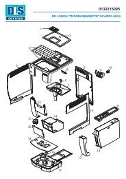
7.1. Outer elements<br />
3<br />
5<br />
1<br />
2<br />
Disassembly of the upper cover<br />
1) Remove the dreg drawer,<br />
water tank, coffee container<br />
cover, water drip tray, brewing<br />
unit, control knob cover and<br />
the cappuccino button (use a<br />
screwdriver as a lever).<br />
2) Loosen the screws shown<br />
and remove the finger protection<br />
mushroom and the coffee<br />
container.<br />
3) Loosen the screws shown from<br />
inside the compartments that<br />
contain the water tank and dreg<br />
drawer.<br />
4) Move the upper cover<br />
outwards to facilitate the removal<br />
of the front panel.<br />
5) Lift the upper cover and<br />
disconnect the earth wire shown.<br />
When assembling the appliance cover, be careful not to<br />
scratch the keyboard cover.<br />
It is recommended to place a sheet of paper on the<br />
keyboard cover (see picture) before repositioning the<br />
appliance cover and remove it when assembly is complete.<br />
Saeco International Group Page 01<br />
/ 09<br />
4
SYNTIA CAPPUCCINO 07 DISASSEMBLY<br />
Side cover<br />
Loosen the screws shown and disconnect the<br />
earth wire.<br />
4<br />
7.2. Coffee dispenser<br />
5<br />
1<br />
3<br />
6<br />
2<br />
Side door<br />
Lift the door and remove it from the support<br />
hinge.<br />
Rear cover<br />
Loosen the screws shown.<br />
1) Loosen the screws shown.<br />
2) Use a screwdriver as a lever to release<br />
the front panel support, which facilitates the<br />
removal of the dispenser.<br />
3) Remove the fork and the clamp.<br />
4/5) Loosen the screws shown.<br />
6) Dispenser assembly.<br />
Saeco International Group Page / 09<br />
02
SYNTIA CAPPUCCINO 07 DISASSEMBLY<br />
7.3. Coffee grinder adjustment<br />
The grinding machine can be adjusted by the user (only with the grinding machine on) by<br />
pressing and turning the knob inside the coffee bean container one notch at a time.<br />
Adjustment implemented by the service centres<br />
C<br />
-<br />
Adjustment knob<br />
+<br />
To further adjust the grinding machine, the technician can<br />
operate directly on the machine by pressing and turning<br />
the highlighted ring nut (C). (clockwise + to increase the<br />
grain size and anti-clockwise - to decrease it).<br />
If coffee residue is found between the two grinder blades,<br />
it is recommended to adjust this by tightening a max of<br />
two notches at a time.<br />
Lastly, bring the middle dot of the adjustment knob back<br />
to the centre.<br />
Saeco International Group Page 03 / 09
SYNTIA CAPPUCCINO 07 DISASSEMBLY<br />
7.4. Keyboard Card and Control Knob<br />
1<br />
3<br />
7.5. Power/CPU Board<br />
1<br />
2<br />
2<br />
4<br />
1) Loosen the screw shown and remove<br />
the cover, glass panel, frame, keyboard and<br />
seal.<br />
2) Release the display support and the<br />
display.<br />
3) Loosen the screws shown and remove<br />
the control knob.<br />
4) Parts.<br />
1) Loosen the screw shown and remove<br />
the board cover.<br />
2) Remove the board by removing all the<br />
connections.<br />
Saeco International Group Page 04/<br />
09
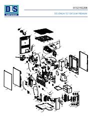
SYNTIA CAPPUCCINO 07 DISASSEMBLY<br />
7.6 Gearmotor<br />
F<br />
D<br />
1<br />
B<br />
B<br />
E<br />
P<br />
C<br />
H<br />
L<br />
A<br />
2<br />
3<br />
4<br />
1) Loosen the screws of the boiler pin, remove it and<br />
loosen the others shown.<br />
2) The following are located inside the compartment<br />
protected by the casing:<br />
- The electric motor (A) with gears (B) and (C) for<br />
transmission and timing of the dispensing unit.<br />
- The dreg drawer presence sensor (D).<br />
- The dispensing unit presence microswitch (E).<br />
- The microswitch (F) that detects the idle phase of<br />
the dispensing unit as well as that of the dispensing<br />
process.<br />
- Remove the gear (C) that engages with the motor<br />
transmission shaft.<br />
- Remove the large gear (B).<br />
- Remove the motor (A) complete with the<br />
transmission shaft.<br />
3) Reconnect the gear (B), making sure that the<br />
arrow is aligned with the opening that contains the<br />
pin (P).<br />
4) When re-mounting the motor and the<br />
transmission shaft, make sure the guides (L) are<br />
inserted in the correct housing.<br />
Grease the shaft thoroughly and evenly.<br />
Saeco International Group Page / 09<br />
05
SYNTIA CAPPUCCINO 07 DISASSEMBLY<br />
7.7. Boiler<br />
7.8. Stopcock<br />
1<br />
2<br />
4<br />
2<br />
1<br />
3<br />
5<br />
1) Loosen the screws shown.<br />
4) Loosen the screw and remove the plastic support.<br />
Disconnect the pipes and the connections.<br />
1) Remove the boiler pin by loosening the<br />
screws shown.<br />
2/3) Loosen the screws shown.<br />
4) Loosen the screws shown and remove<br />
the structure base insert.<br />
5) Loosen the screws shown and remove<br />
the water connections and the stopcock.<br />
Saeco International Group Page 06/<br />
09
FLOW METER<br />
SYNTIA CAPPUCCINO 07 DISASSEMBLY<br />
7.9. Pump and flow meter<br />
2<br />
FROTHER<br />
FROTHED MILK/HOT WATER<br />
2<br />
1<br />
7.10. Solenoid valves<br />
3-WAY SOLENOID VALVE<br />
MILK CARAFE<br />
BOILER<br />
3<br />
EV2<br />
WATER DRAIN<br />
PUMP<br />
Remove the connection 1 and the silicone pipes 2.<br />
Loosen the safety valve 3 and remove the pump<br />
from the two supports.<br />
2-WAY SOLENOID VALVE<br />
DRAIN<br />
COFFEE<br />
DISPENSER<br />
UNIT<br />
EV1<br />
- COLD WATER<br />
- HOT WATER/STEAM<br />
FLOW METER<br />
Remove the connection and the silicone pipes<br />
and release the flow meter.<br />
2-way solenoid valve<br />
Remove all electrical and water connections.<br />
3-way solenoid valve<br />
Loosen the screw shown and remove the<br />
electrical and water connections.<br />
Saeco International Group Page 07/<br />
09
SYNTIA CAPPUCCINO 07 DISASSEMBLY<br />
7.11 Coffee grinder<br />
A<br />
B<br />
1<br />
2<br />
1) To remove the coffee grinder, simply slide<br />
it out and remove the connections.<br />
2) When reassembling it, make sure the<br />
spring (A) and the coffee duct (B) are<br />
repositioned correctly.<br />
7.12. Adjusting/removing and installing the grinder blades<br />
1<br />
2<br />
1) To remove the upper grinder blade<br />
support, use an Allen wrench and turn it<br />
clockwise to release it from the bayonet<br />
coupling.<br />
2) To remove the grinder blade from the<br />
upper support, turn it anti-clockwise until it<br />
is released from the bayonet coupling.<br />
Saeco International Group Page 08/<br />
09
SYNTIA CAPPUCCINO 07 DISASSEMBLY<br />
A<br />
7.13. Un/installing Oetiker clamps<br />
1<br />
2<br />
Use a suitable pair of pliers to remove the<br />
clamp (as shown).<br />
3<br />
4<br />
1) Boiler connection<br />
2) Other connections<br />
3) To remove the lower grinder blade, block the<br />
increment pin (A) in place and turn the grinder<br />
blade anti-clockwise until it is released from the<br />
bayonet coupling.<br />
4) When refitting the upper grinder blade<br />
support, make sure it is placed as shown in the<br />
picture, with the highlighted mark in the same<br />
position.<br />
Tighten the clamp as shown in the<br />
pictures.<br />
Saeco International Group Page 09<br />
/ 09
Saeco International Group SYNTIA CAPPUCCINO
SYNTIA CAPPUCCINO 08 NOTES<br />
Saeco International Group Page 01<br />
/ 01
Saeco International Group SYNTIA CAPPUCCINO
SYNTIA CAPPUCCINO 09 WATER CIRCUIT DIAGRAM<br />
DRAIN<br />
Silicone wire pipe 5x10 9972.122 (290 mm)<br />
FLOW METER<br />
Silicone wire pipe 5x8.9 11003557 (260 mm)<br />
3-WAY SOLENOID VALVE 2-WAY SOLENOID VALVE<br />
Silicone wire pipe 5x8.9 11003557 (260 mm)<br />
FROTHER<br />
Silicone wire pipe 5x8.9 11024510 (95 mm)<br />
WATER<br />
TANK<br />
Silicone wire pipe 5x10 9972.176 (130 mm)<br />
MILK<br />
CARAFE<br />
Silicone wire pipe 5x10 9972.176 (130 mm)<br />
4 Bar VALVE<br />
BOILER<br />
FROTHED<br />
MILK<br />
Saeco International Group Page 01 / 01<br />
PUMP<br />
COFFEE<br />
DISPENSER<br />
UNIT<br />
Silicone wire pipe 5x8.9 11003557 (260 mm)<br />
Silicone wire pipe 5x8.9 11005599 (190 mm)<br />
Silicone pipe 5x10 9972.122 (290 mm)<br />
SAFETY VALVE ASSEMBLY
Saeco International Group SYNTIA CAPPUCCINO
SYNTIA CAPPUCCINO 10 ELECTRICAL DIAGRAM<br />
Saeco International Group Page 01/<br />
01