Bunn Axiom-3 Repair Manual - The Coffee Bump
Bunn Axiom-3 Repair Manual - The Coffee Bump
Bunn Axiom-3 Repair Manual - The Coffee Bump

You also want an ePaper? Increase the reach of your titles
YUMPU automatically turns print PDFs into web optimized ePapers that Google loves.
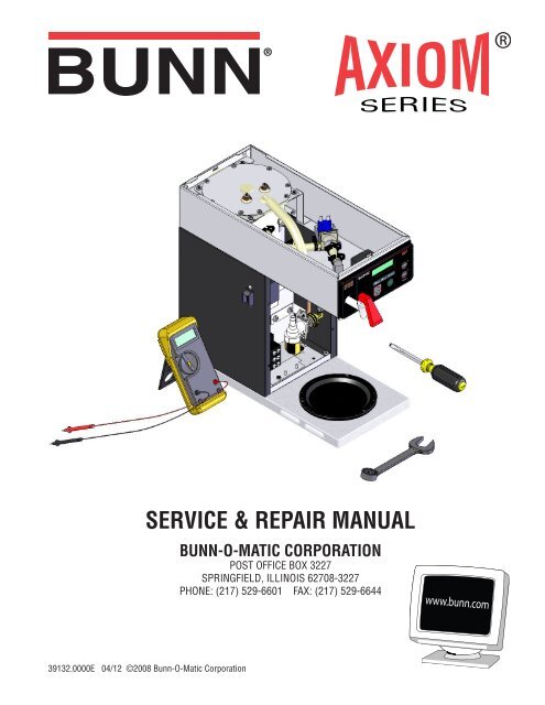
SERVICE & REPAIR MANUAL<br />
39132.0000E 04/12 ©2008 <strong>Bunn</strong>-O-Matic Corporation<br />
BUNN-O-MATIC CORPORATION<br />
POST OFFICE BOX 3227<br />
SPRINGFIELD, ILLINOIS 62708-3227<br />
PHONE: (217) 529-6601 FAX: (217) 529-6644
BUNN-O-MATIC COMMERCIAL PRODUCT WARRANTY<br />
<strong>Bunn</strong>-O-Matic Corp. (“BUNN”) warrants equipment manufactured by it as follows:<br />
1) Airpots, thermal carafes, decanters, GPR servers, iced tea/coffee dispensers, MCP/MCA pod brewers thermal<br />
servers and <strong>The</strong>rmofresh servers (mechanical and digital)- 1 year parts and 1 year labor.<br />
2) All other equipment - 2 years parts and 1 year labor plus added warranties as specifi ed below:<br />
a) Electronic circuit and/or control boards - parts and labor for 3 years.<br />
b) Compressors on refrigeration equipment - 5 years parts and 1 year labor.<br />
c) Grinding burrs on coffee grinding equipment to grind coffee to meet original factory screen sieve analysis<br />
- parts and labor for 4 years or 40,000 pounds of coffee, whichever comes fi rst.<br />
<strong>The</strong>se warranty periods run from the date of installation BUNN warrants that the equipment manufactured by<br />
it will be commercially free of defects in material and workmanship existing at the time of manufacture and appearing<br />
within the applicable warranty period. This warranty does not apply to any equipment, component or<br />
part that was not manufactured by BUNN or that, in BUNN’s judgment, has been affected by misuse, neglect,<br />
alteration, improper installation or operation, improper maintenance or repair, non periodic cleaning and descaling,<br />
equipment failures related to poor water quality, damage or casualty. In addition, the warranty does not<br />
apply to replacement of items subject to normal use including but not limited to user replaceable parts such as<br />
seals and gaskets. This warranty is conditioned on the Buyer 1) giving BUNN prompt notice of any claim to be<br />
made under this warranty by telephone at (217) 529-6601 or by writing to Post Offi ce Box 3227, Springfi eld,<br />
Illinois 62708-3227; 2) if requested by BUNN, shipping the defective equipment prepaid to an authorized BUNN<br />
service location; and 3) receiving prior authorization from BUNN that the defective equipment is under warranty.<br />
THE FOREGOING WARRANTY IS EXCLUSIVE AND IS IN LIEU OF ANY OTHER WARRANTY, WRITTEN OR<br />
ORAL, EXPRESS OR IMPLIED, INCLUDING, BUT NOT LIMITED TO, ANY IMPLIED WARRANTY OF EITHER<br />
MERCHANTABILITY OR FITNESS FOR A PARTICULAR PURPOSE. <strong>The</strong> agents, dealers or employees of BUNN<br />
are not authorized to make modifi cations to this warranty or to make additional warranties that are binding on<br />
BUNN. Accordingly, statements by such individuals, whether oral or written, do not constitute warranties and<br />
should not be relied upon.<br />
If BUNN determines in its sole discretion that the equipment does not conform to the warranty, BUNN, at its<br />
exclusive option while the equipment is under warranty, shall either 1) provide at no charge replacement parts<br />
and/or labor (during the applicable parts and labor warranty periods specifi ed above) to repair the defective<br />
components, provided that this repair is done by a BUNN Authorized Service Representative; or 2) shall replace<br />
the equipment or refund the purchase price for the equipment.<br />
THE BUYER’S REMEDY AGAINST BUNN FOR THE BREACH OF ANY OBLIGATION ARISING OUT OF THE SALE<br />
OF THIS EQUIPMENT, WHETHER DERIVED FROM WARRANTY OR OTHERWISE, SHALL BE LIMITED, AT<br />
BUNN’S SOLE OPTION AS SPECIFIED HEREIN, TO REPAIR, REPLACEMENT OR REFUND.<br />
In no event shall BUNN be liable for any other damage or loss, including, but not limited to, lost profi ts, lost<br />
sales, loss of use of equipment, claims of Buyer’s customers, cost of capital, cost of down time, cost of substitute<br />
equipment, facilities or services, or any other special, incidental or consequential damages.<br />
392, AutoPOD, AXIOM, BrewLOGIC, BrewMETER, Brew Better Not Bitter, BrewWISE, BrewWIZARD, BUNN<br />
Espress, BUNN Family Gourmet, BUNN Gourmet, BUNN Pour-O-Matic, BUNN, BUNN with the stylized red line,<br />
BUNNlink, <strong>Bunn</strong>-OMatic, <strong>Bunn</strong>-O-Matic, BUNNserve, BUNNSERVE with the stylized wrench design, Cool Froth,<br />
DBC, Dr. Brew stylized Dr. design, Dual, Easy Pour, EasyClear, EasyGard, FlavorGard, Gourmet Ice, Gourmet<br />
Juice, High Intensity, iMIX, Infusion Series, Intellisteam, My Café, Phase Brew, PowerLogic, Quality Beverage<br />
Equipment Worldwide, Respect Earth, Respect Earth with the stylized leaf and coffee cherry design, Safety-<br />
Fresh, savemycoffee.com, Scale-Pro, Silver Series, Single, Smart Funnel, Smart Hopper, SmartWAVE, Soft Heat,<br />
SplashGard, <strong>The</strong> Mark of Quality in Beverage Equipment Worldwide, <strong>The</strong>rmoFresh, Titan, trifecta, Velocity Brew,<br />
A Partner You Can Count On, Air Brew, Air Infusion, Beverage Bar Creator, Beverage Profi t Calculator, Brew<br />
better, not bitter., BUNNSource, <strong>Coffee</strong> At Its Best, Cyclonic Heating System, Daypart, Digital Brewer Control,<br />
Nothing Brews Like a BUNN, Pouring Profi ts, Signature Series, Tea At Its Best, <strong>The</strong> Horizontal Red Line, Ultra<br />
are either trademarks or registered trademarks of <strong>Bunn</strong>-O-Matic Corporation.<br />
Page 2<br />
39132 030912
INTRODUCTION<br />
This equipment will brew a half-gallon batch of coffee into an awaiting dispenser. It can be easily confi gured for<br />
120V 15 amp, 120/208V 20 amp or 120/240V 20 amp. <strong>The</strong> brewer may have a hot water faucet for allied beverage use.<br />
It is only for indoor use on a sturdy counter or shelf.<br />
CONTENTS<br />
Troubleshooting ..................................................................................................4<br />
Diagnostics .........................................................................................................9<br />
Technician Programming Reminders ................................................................10<br />
Access ..............................................................................................................11<br />
Control Board ....................................................................................................12<br />
Face Plate ..........................................................................................................13<br />
Membrane Switch .............................................................................................13<br />
Brew Valve ........................................................................................................14<br />
Optional Brew Valve ..........................................................................................15<br />
Level Probes .....................................................................................................16<br />
Early Refi ll Valve ...............................................................................................17<br />
Later Refi ll Valve ...............................................................................................18<br />
Tank Heaters .....................................................................................................20<br />
Limit <strong>The</strong>rmostat ...............................................................................................21<br />
<strong>The</strong>rmal Cut Off .................................................................................................21<br />
Blanket Warmer ................................................................................................22<br />
Temperature Probe............................................................................................23<br />
Warmer Elements..............................................................................................24<br />
Voltage Selector Switch ....................................................................................25<br />
Power Switch ....................................................................................................26<br />
Programming Level 3 ........................................................................................27<br />
Programming Level 4 ........................................................................................29<br />
Wiring Diagrams .............................................................................................. 30<br />
Schematics .......................................................................................................34<br />
Page 3<br />
39132 062309
TROUBLESHOOTING<br />
A troubleshooting guide is provided to suggest probable causes and remedies for the most likely problems<br />
encountered. If the problem remains after exhausting the troubleshooting steps, contact the <strong>Bunn</strong>-O-Matic<br />
Technical Service Department.<br />
Inspection, testing, and repair of electrical equipment should be performed only by qualifi ed service personnel.<br />
All electronic components have ac line voltage and some have low voltage dc potential on their terminals.<br />
Shorting of terminals or the application of external voltages may result in board failure.<br />
Intermittent operation of electronic circuit boards is unlikely. Board failure will normally be permanent. If<br />
an intermittent condition is encountered, the cause will likely be a switch contact or a loose connection at a<br />
terminal or crimp.<br />
Solenoid removal requires interrupting the water supply to the valve. Damage may result if solenoids are<br />
energized for more than ten minutes without a supply of water.<br />
<strong>The</strong> use of two wrenches is recommended whenever plumbing fi ttings are tightened or loosened. This will<br />
help to avoid twists and kinks in the tubing.<br />
Make certain that all plumbing connections are sealed and electrical connections tight and isolated.<br />
This brewer is heated at all times. Keep away from combustibles.<br />
WARNING<br />
Exercise extreme caution when servicing electrical equipment.<br />
Unplug the brewer when servicing, except when electrical tests are specifi ed.<br />
Follow recommended service procedures.<br />
Replace all protective shields or safety notices.<br />
Before assuming a faulty control board, check for the following:<br />
Control Boards<br />
1. Make sure ribbon cable is properly attached to the control board (ALL PINS INSERTED INTO PLUG).<br />
2. Make sure there is a nylon insulating washer under each screw head that holds the control board to the<br />
plastic front end cap. This is important for proper operation.<br />
3. Make sure, before servicing brewer that voltage is present at control board.<br />
4. Press any warmer switch (if equipped) or observe if any indicator lights are glowing on the control panel.<br />
If so, proceed with testing. If not, check for voltage across pins 1 & 2 of the ten pin J1 connector (black and<br />
white wires). If voltage is present, replace the control board. If voltage is not present, check wiring and voltage<br />
across terminal block (black and white on 120 & 120/240 models, or black and red on A models). Correct the<br />
problem and retest before proceeding with testing.<br />
Page 4<br />
39132 062309
TROUBLESHOOTING (cont.)<br />
REFILL CIRCUIT<br />
PROBLEM<br />
Will not refi ll<br />
Refi ll does not shut off<br />
Power "ON"<br />
Refi ll does not shut off<br />
Power "OFF"<br />
PROBABLE CAUSE REMEDY<br />
1. Power off to brewer<br />
2. Water shut off<br />
3. Error Message<br />
4.ON/OFF Switch<br />
(If equipped)<br />
5. Lime build up on Probe(s)<br />
6. Refi ll Valve or Control Board<br />
1. Lime build up on probe<br />
2. Water Level Sensing System<br />
3. Refi ll valve or control board<br />
1. Refi ll valve<br />
Page 5<br />
Press OFF/ON switch on control<br />
panel to determine if power is ON.<br />
Make sure water is ON.<br />
Brewer has shut down due to malfunction<br />
(See Diagnostic Section in<br />
this manual).<br />
Make sure ON/OFF Switch is "ON"<br />
and indicator is lit.<br />
Remove the Level Probe(s) and<br />
check for lime deposit on tip. Clean<br />
and reinstall.<br />
Refer to page 19<br />
Remove Level Probe and check<br />
for lime deposits on tip. Clean and<br />
reinstall.<br />
Replace control board<br />
Check valve. Page 19<br />
Clean or replace valve as needed.<br />
Page 19<br />
39132 080409
TROUBLESHOOTING (cont.)<br />
HEATING CIRCUIT<br />
PROBLEM<br />
Water does not heat to proper<br />
temperature<br />
IMPORTANT: Make sure no temperature<br />
tests are taken before<br />
the display reads ready. Tank temperature<br />
must be stabilized before<br />
readings are taken.<br />
Spitting or excessive steaming<br />
(cont.)<br />
Brewer is making unusual noises<br />
PROBABLE CAUSE REMEDY<br />
1. Display's error message<br />
2. Water not touching main (short)<br />
level probe<br />
3. Water Level Probe Sensing<br />
System<br />
4. Temperature Probe<br />
5. Limit <strong>The</strong>rmostat or TCO<br />
6. Tank Heater<br />
1. Lime build up on temperature<br />
probe, tank or tank heater<br />
2. Temperature Probe<br />
3. Control Board<br />
1. Plumbing lines<br />
2. Water supply<br />
3. Lime build up<br />
Page 6<br />
Brewer has shut down due to malfunction.<br />
See Diagnostics.<br />
Remove level probe and grommet.<br />
Look into hole on tank lid. Water<br />
must be within approximately one<br />
inch from top of tank.<br />
Check refi ll circuit. Heaters will not<br />
turn on if water is not grounding<br />
level probe.<br />
Check/replace<br />
Check/replace<br />
Check/replace<br />
Inspect probe and tank assembly<br />
for excessive lime deposits. Delime<br />
as required.<br />
Check/replace<br />
Check/replace<br />
Plumbing lines should not rest on<br />
the counter top.<br />
<strong>The</strong> brewer must be connected to<br />
a cold water supply.<br />
Remove the tank lid and clean inside<br />
of tank with a deliming agent,<br />
if necessary.<br />
39132 041708
TROUBLESHOOTING (cont.)<br />
BREWING CIRCUIT<br />
PROBLEM PROBABLE CAUSE REMEDY<br />
Brew cycle will not start<br />
1. Display's error message Brewer has shut down due to malfunction.<br />
See Diagnostics.<br />
Consistently low beverage level in<br />
the dispenser or beverage overfl ows<br />
dispenser<br />
Brew cycle starts, then aborts and<br />
returns to Main screen after 20<br />
seconds (SB 153)<br />
2. No water<br />
3. No power or incorrect voltage to<br />
the brewer<br />
4. ON/OFF switch not in the "ON"<br />
position<br />
5. Low water temperature (Brew<br />
lockout is enabled)<br />
6. Water not touching refi ll probe<br />
inside tank<br />
7. Membrane Switch<br />
8. Dispense valve<br />
9. Control board<br />
1. Brew volume<br />
NOTE: Volume adjustments must be<br />
made with sprayhead installed.<br />
2. Lime build up<br />
3. Dispense Valve<br />
1. Level probes shorted<br />
2. On pour over models, the operator<br />
poured in water and pressed the<br />
start button<br />
Page 7<br />
Water lines and valves to the brewer<br />
must be open.<br />
Check for voltage across the terminals<br />
at the terminal block.<br />
<strong>The</strong> indicator lamp must be lit<br />
Allow brewer to heat until ready, or<br />
disable the brew lockout feature.<br />
Water must be in contact with refi ll<br />
probe before brew cycle will start.<br />
Check/replace<br />
Check/replace<br />
Check/replace<br />
Inspect the dispense valve and<br />
sprayhead for excessive lime deposits.<br />
Delime as required.<br />
Remove dispense valve and clear<br />
any obstructions. Rebuild or replace<br />
valve if necessary. (See page 24)<br />
Check/replace<br />
Delime as required.<br />
Ensure mylar shield(s) are installed<br />
on top cover<br />
Instruct operator to use one procedure<br />
but not both<br />
39132 061809
TROUBLESHOOTING (cont.)<br />
BREWING CIRCUIT (cont.)<br />
PROBLEM PROBABLE CAUSE REMEDY<br />
Dripping from sprayhead<br />
Weak beverage<br />
Dry coffee grounds remain in<br />
the funnel<br />
Low beverage serving temperature<br />
1. Lime build up<br />
2. Dispense valve<br />
1. Sprayhead<br />
2. Water temperature<br />
3. Filter type<br />
4. <strong>Coffee</strong> grind<br />
5. Funnel loading<br />
1. Sprayhead<br />
2. Funnel loading<br />
1. Warmer<br />
2. <strong>The</strong>rmal server/AirPot not<br />
preheated before brew cycle<br />
Page 8<br />
Inspect the tank assembly for<br />
excessive lime deposits. Delime<br />
as required.<br />
Check/replace<br />
A clean sprayhead must be used<br />
for proper extraction.<br />
Place an empty brew funnel<br />
on an empty decanter beneath<br />
the sprayhead. Initiate brew<br />
cycle and check the water temperature<br />
immediately below the<br />
sprayhead with a thermometer.<br />
<strong>The</strong> reading must not be less<br />
than 195°F (91°C). Adjust the<br />
temperature setting to increase<br />
the water temperature. Refer to<br />
Initial Set-up instructions.<br />
BUNN® paper fi lters must be<br />
used for proper extraction.<br />
A fi ne drip or grind must be used<br />
for proper extraction.<br />
<strong>The</strong> BUNN® paper fi lter must<br />
be centered in the funnel and<br />
the bed of grounds leveled by<br />
shaking gently.<br />
Make sure sprayhead is present<br />
and holes are clear and<br />
unobstructed.<br />
<strong>The</strong> BUNN® paper fi lter must<br />
be centered in the funnel and<br />
the bed of grounds leveled by<br />
shaking gently.<br />
Check/replace<br />
Preheat server<br />
39132 041708
DIAGNOSTICS<br />
MESSAGE<br />
"CHECK SPRAYHEAD FOR LIME" -<br />
"CHECK FITTINGS FOR LIME"<br />
"WARNING INACCURATE FLOW"<br />
- "TOO MUCH LIME PLEASE RE-<br />
PAIR"<br />
"WARNING VERY LOW FLOW" -<br />
"PLEASE REPAIR"<br />
Temperature Too Low<br />
Heating Time Too Long<br />
Fill Time Too Long<br />
Temp Sensor Out Of Range, Check<br />
For Bad Connections<br />
Temp Sensor Out Of Range, Check<br />
Wire For Shorts<br />
PROBABLE CAUSE REMEDY<br />
1. Lime buildup in sprayhead<br />
2. Lime buildup in brew valve<br />
3. Lime buildup in brew tank<br />
1. Lime buildup in sprayhead<br />
2. Lime buildup in brew valve<br />
3. Lime buildup in brew tank<br />
1. Lime buildup in sprayhead<br />
2. Lime buildup in brew valve<br />
3. Lime buildup in brew tank<br />
1. Water temperature in the tank<br />
does not meet the ready temperature.<br />
1. Tank Heater failure.<br />
2. Control Board/<strong>The</strong>rmistor failure<br />
1. Water shut off to brewer<br />
2. Supply line too small or obstructed<br />
3. Inlet Solenoid failure<br />
4. Control Board Failure<br />
5. ON/OFF switch is OFF<br />
1. Temperature Sensor Probe<br />
open<br />
1. Temperature Sensor Probe<br />
wire(s) shorted<br />
Page 9<br />
Clean sprayhead<br />
Clean valve<br />
Clean tank<br />
Clean sprayhead<br />
Clean valve<br />
Clean tank<br />
Clean sprayhead<br />
Clean valve<br />
Clean tank<br />
A) Wait for the brewer to heat to<br />
the proper temperature.<br />
B) Disable the BREW LOCKOUT<br />
function. Refer to programming<br />
section for procedure.<br />
Replace or repair as needed<br />
Replace or repair as needed<br />
Check water supply shut-off<br />
Replace or repair as needed<br />
Replace or repair as needed<br />
Replace or repair as needed<br />
Turn switch ON<br />
Replace or repair as needed<br />
Replace or repair as needed<br />
39132 041708
TECHNICIAN PROGRAMMING REMINDERS<br />
REVERSE FORWARD<br />
Page 10<br />
AXIOM<br />
VERSION ##.##<br />
VIEW ASSET/SERIAL # ENTER PROGRAMMING<br />
ACCESSING PROGRAM MODES<br />
Press and hold the right hidden switch. <strong>The</strong> longer you press it, the higher the level you can access. EXAMPLE:<br />
Pressing for a couple seconds enters Level 1. Continuing to press for approximately 5 seconds will access Level<br />
2. Continue pressing for approximately 15 seconds to access Level 3. During program modes, use the right hidden<br />
switch to advance forward through screens. Use left hidden switch to step backwards through screens.<br />
VIEWING ASSET AND SERIAL NUMBERS<br />
Press left hidden switch to view Asset number. Press and release to view serial number. Press and release again<br />
to view the installed software version.<br />
FACTORY BLOWOUT MODE<br />
When in the main screen, DO NOT press both left and right hidden switches at the same time. <strong>The</strong> display will<br />
read "FACTORY BLOWOUT" "ON/OFF". WARNING: NEVER activate this mode. It will open the brew and refi ll<br />
valves simultaneously. THIS IS FOR FACTORY USE ONLY! If you accidentally enter this screen, exit out of it<br />
by pressing the "ENABLE BREW ON/OFF" switch.<br />
PROGRAMMING LOCKOUT SWITCH<br />
(Mounted on main control board)<br />
This switch can be set to prevent access<br />
to Level 2. Turn "OFF" the switch to access<br />
Technician (Level 2). Once all the correct brew<br />
settings are programmed, the Technician can<br />
set the switch to the "ON" position to prohibit<br />
anyone from changing the settings. With the<br />
switch in the "ON" position, only Level 1 can<br />
be accessed by store personnel. Technicians<br />
can access Level 1 with the switch in either<br />
position. To enter Levels 2, 3, & 4, press and<br />
hold right hidden switch.<br />
39132 062309
COMPONENT ACCESS<br />
This section provides procedures for testing and<br />
replacing various major components used in this<br />
brewer should service become necessary. Refer to<br />
Troubleshooting for assistance in determining the<br />
cause of any problem.<br />
WARNING - Inspection, testing, and repair of electrical<br />
equipment should be performed only by qualifi ed<br />
service personnel. <strong>The</strong> brewer should be unplugged<br />
when servicing, except when electrical tests are required<br />
and the test procedure specifi cally states to<br />
plug in the brewer.<br />
WARNING - Disconnect the brewer from the power<br />
source before the removal of any panel or the replacement<br />
of any component.<br />
All components are accessible by the removal of<br />
the top cover or warmer housing, front access panel<br />
and warmer plate(s).<br />
Refer to wiring diagrams at the back of this manual<br />
when reconnecting wires.<br />
Page 11<br />
FIG. 11-1 COMPONENT ACCESS<br />
FIG. 11-2 COMPONENT ACCESS<br />
39132 062309
CONTROL BOARD<br />
FIG. 12-1 CONTROL BOARD<br />
Location:<br />
<strong>The</strong> Control Board is located inside the top cover<br />
behind the front face plate.<br />
Test Procedures:<br />
<strong>The</strong> test procedures for the control board will vary<br />
depending upon the problems experienced by the<br />
brewer. Refer to the Troubleshooting section which<br />
is divided into three sections, Refi ll Circuit, Heating<br />
Circuit, and Brewing Circuit.<br />
Check for Power to board:<br />
1. Insert one meter lead in J1-pin 1 and the other<br />
lead in J1-pin 2.<br />
2. With the power connected to brewer, the voltage<br />
reading to the board should be the line voltage rated<br />
for that model.<br />
If no voltage is present, check wiring to the board.<br />
If voltage is present, and brewer does not power<br />
on, replace board.<br />
Removal and Replacement:<br />
1. Disconnect brewer from power source.<br />
2. Disconnect the wires from the relay on the control<br />
board.<br />
3. Disconnect the 10-pin connector (main harness)<br />
and the 3-pin connector (level probe harness) from<br />
the control board.<br />
4. Disconnect the 10-pin connector (ribbon cable)<br />
from the control board.<br />
Page 12<br />
5. Remove the two screws and two nylon washers<br />
securing the control board to the front face plate.<br />
6. Tilt the control board inward to clear the display<br />
section.<br />
7. Place the bottom edge of the new control board<br />
in the two cradles, tilt the board forward, and secure<br />
with the two screws and nylon washers to the front<br />
face plate.<br />
NOTE: <strong>The</strong> nylon washers must be installed under<br />
the heads of the two screws to prevent a possible<br />
shorting of the control board circuits.<br />
8. Re-install wires & connectors.<br />
BEFORE REPLACEMENT:<br />
If a triac or MOV is visibly burned, it was most likely<br />
caused by an external sources such as a shorted wire<br />
or damaged solenoid coil. Use the triac map below to<br />
trace the circuit in question, and repair/replace the<br />
component before replacing control board.<br />
FIG. 12-2 TRIACS<br />
Triac Map:<br />
TH1 Warmer<br />
TH2/MOV-1 Brew solenoid<br />
TH3 Warmers<br />
TH4/MOV-2 Refi ll solenoid<br />
TH5 Main warmer<br />
MOV2<br />
MOV1<br />
TH5<br />
TH4<br />
TH3<br />
TH2<br />
TH1<br />
@ J1-7<br />
@ J1-10<br />
@ J1-4&8<br />
@ J1-5<br />
@ J1-6<br />
39132 041708
FACEPLATE REMOVAL<br />
Faceplate Removal and Replacement:<br />
1. Disconnect brewer from power source.<br />
2. Disconnect the wires from the relay on the control<br />
board.<br />
3. Disconnect the 10-pin connector (main harness)<br />
and the 3-pin connector (level probe harness) from<br />
the control board.<br />
4. Disconnect the 10-pin connector (ribbon cable)<br />
from the control board.<br />
5. Drain tank and disconnect/remove faucet.<br />
6. Remove the 3 nuts and 1 standoff from back side<br />
of faceplate assembly.<br />
7. Remove faceplate and control board as an assembly<br />
out the front opening.<br />
FIG. 13-1 FACEPLATE REMOVAL<br />
Page 13<br />
8. Remove the two screws and two nylon washers<br />
securing the control board to the front face plate.<br />
9. Place the bottom edge of the new control board in<br />
the two cradles and secure with the two screws and<br />
nylon washers to the front face plate.<br />
NOTE: <strong>The</strong> nylon washers must be installed under<br />
the heads of the two screws to prevent a possible<br />
shorting of the control board circuits.<br />
10. Re-install faucet assembly (if equipped).<br />
11. Re-install faceplate/board assembly.<br />
12. Re-install wires & connectors.<br />
39132 061809
MEMBRANE SWITCH<br />
FIG. 14-1 MEMBRANE SWITCH<br />
Location:<br />
<strong>The</strong> Membrane Switch is located on the front face<br />
plate.<br />
Test Procedures:<br />
<strong>The</strong>re are two methods for testing the membrane<br />
switch. <strong>The</strong> easiest method is to use the built in test<br />
mode. Refer to the Programing Section for Service<br />
Tools/Test Switches. If for some reason you can't get<br />
into the program modes, or brewer won't power up,<br />
FIG. 14-2 MEMBRANE SWITCH CONTINUITY<br />
Page 14<br />
you can test it with an ohmmeter or continuity tester.<br />
Refer to the schematic to trace the appropriate pins.<br />
NOTE: Pin 1 is the static shield & will not provide a<br />
reading to the other pins. <strong>The</strong>re are two commons<br />
in this circuit, pins 9 & 10.<br />
Disconnect brewer from power source before disconnecting<br />
ribbon cable from control board.<br />
Removal and Replacement:<br />
1. Disconnect the ribbon cable from 10-pin connector<br />
on the control board.<br />
2. Gently peel the membrane switch from the front<br />
face plate assembly.<br />
4 Remove any adhesive that remains on the front<br />
face plate.<br />
5. Remove the adhesive backing from the new membrane<br />
switch. Insert the ribbon cable through the slot<br />
in the front face plate and apply the membrane switch<br />
to the front face plate.<br />
6. Connect the ribbon cable to the 10-pin connector on<br />
the control board making sure every pin on the control<br />
board is inserted into the ribbon cable connector.<br />
Helpful<br />
Hint<br />
Wrap a thin paper clip around each meter lead<br />
and extend past the tip by ¼" - ½". You may<br />
need to sand off the clear coating on some clips!<br />
39132 100609
BREW VALVE<br />
FIG. 15-1 BREW VALVE<br />
Location:<br />
<strong>The</strong> brew valve is located inside the top cover behind<br />
the front face plate.<br />
Test Procedures:<br />
1. Refer to the Programing Section for Service Tools/<br />
Test Outputs/Brew Valve.<br />
2. Be sure brew funnel & server are in place before<br />
activating valve.<br />
3. Check the valve for coil action. Turn on the valve<br />
with the test mode. Listen carefully in the vicinity of<br />
the brew valve for a click as the coil pulls the plunger<br />
in.<br />
If no sound is heard as described, proceed to #4.<br />
If the sound is heard as described, there may be a<br />
blockage in the valve , hose, tank, or sprayhead. Disconnect<br />
the brewer from the power source. Remove<br />
the valve and inspect for blockage, and de-lime all<br />
related areas.<br />
4. Connect the voltmeter leads to the coil terminals.<br />
Turn on the valve with the test mode.<br />
NOTE: Due to the internally rectifi ed coil, the indication<br />
will be 120VAC all the time. Set the meter<br />
to DC volts. <strong>The</strong> indication should be 170VDC when<br />
activated. If the polarity of meter leads are reversed,<br />
reading will indicate -170VDC. (Double these readings<br />
for 240 volt coils)<br />
If voltage is present as described, but no coil action is<br />
Page 15<br />
observed, brew valve is defective. Replace valve and<br />
test again to verify repair.<br />
If voltage is not present as described, refer to Wiring<br />
Diagrams and check the brewer wiring harness.<br />
Also check the control board and switch for proper<br />
operation.<br />
Removal and Replacement:<br />
1. Disconnect the brewer from the power source.<br />
2. Disconnect wires from the valve.<br />
3. Drain enough water from the tank so the water<br />
level is below the outlet.<br />
4. Remove hoses from the valve.<br />
5. Remove the two #8-32 nuts securing the valve to<br />
the sprayhead panel.<br />
6. Install new valve using the two #8-32 nuts.<br />
7. Reconnect hoses to the valve and secure in place<br />
with clamps.<br />
FIG. 15-2 BREW VALVE<br />
Due to the internally rectifi ed coil, do not attempt to<br />
test this type of coil with an ohmmeter. <strong>The</strong> reading<br />
will be open or very high resistance, depending<br />
on the polarity of your meter leads.<br />
39132 041708
OPTIONAL BREW VALVE (ON SELECT MODELS)<br />
FIG. 16-1 OPTIONAL BREW VALVE<br />
Location:<br />
<strong>The</strong> brew valve is located inside the top cover behind<br />
the front face plate.<br />
Test Procedures:<br />
1. Refer to the Programing Section for Service Tools/<br />
Test Outputs/Brew Valve.<br />
2. Be sure brew funnel & server are in place before<br />
activating valve.<br />
3. Check the valve for coil action. Turn on the valve<br />
with the test mode. Listen carefully in the vicinity of<br />
the brew valve for a click as the coil pulls the plunger<br />
in.<br />
If no sound is heard as described, proceed to #4.<br />
If the sound is heard as described, there may be a<br />
blockage in the valve , hose, tank, or sprayhead. Disconnect<br />
the brewer from the power source. Remove<br />
the valve and inspect for blockage, and de-lime all<br />
related areas.<br />
4. Connect the voltmeter leads to the coil terminals.<br />
Turn on the valve with the test mode.<br />
NOTE: Due to the internally rectifi ed coil, the indication<br />
will be 120VAC all the time. Set the meter<br />
to DC volts. <strong>The</strong> indication should be 170VDC when<br />
activated. If the polarity of meter leads are reversed,<br />
reading will indicate -170VDC. (Double these readings<br />
for 240 volt coils)<br />
If voltage is present as described, but no coil action is<br />
Page 16<br />
observed, brew valve is defective. Replace valve and<br />
test again to verify repair.<br />
If voltage is not present as described, refer to Wiring<br />
Diagrams and check the brewer wiring harness.<br />
Also check the control board and switch for proper<br />
operation.<br />
Removal and Replacement:<br />
1. Disconnect the brewer from the power source.<br />
2. Disconnect wires from the valve.<br />
3. Drain enough water from the tank so the water<br />
level is below the outlet.<br />
4. Remove sprayhead and hose from the valve.<br />
5. Remove the nut securing the valve to the sprayhead<br />
panel.<br />
6. Install new valve using the nut from step 5.<br />
7. Reinstall sprayhead and hose to the valve and<br />
secure in place with clamps.<br />
FIG. 16-2 OPTIONAL BREW VALVE<br />
Due to the internally rectifi ed coil, do not attempt to<br />
test this type of coil with an ohmmeter. <strong>The</strong> reading<br />
will be open or very high resistance, depending on<br />
the polarity of your meter leads.<br />
39132 041708
LEVEL PROBE SYSTEM<br />
FIG. 17-1 LEVEL PROBES<br />
Location:<br />
<strong>The</strong> level probes are located inside the tank lid.<br />
Operation:<br />
<strong>The</strong> level probes sense the water level in the tank<br />
by the conductive minerals in the water grounding<br />
out the very low AC voltage applied to the probes. <strong>The</strong><br />
circuit monitors the time it takes the water to drop<br />
the distance from the short probe to the long probe.<br />
Proper "initial set up", and keeping mineral build up<br />
off the probes/grommets, is required for this system<br />
to operate properly. A brew abort feature is "built in".<br />
In the event that the drop in water level from the short<br />
probe to the long probe takes too long, the brew cycle<br />
will abort and return to the main screen. This could<br />
be caused by: Mineral build up on probes/grommets<br />
(very hard water); probes shorting to top cover (verify<br />
the mylar shield(s) are installed; plugged outlet (ie:<br />
sprayhead limed up); incorrect operator use with the<br />
pour over model (ie: pour in water and pressing "start"<br />
button)<br />
Test Procedures:<br />
1. Enter programming level 2, scroll to "Refi ll". NOTE:<br />
This screen only reads the long probe (blue wire) and<br />
is used for setting the refi ll conductance threshold.<br />
Alternate: Scroll to "Service Tools".<br />
<strong>The</strong>n scroll to "LP1 & LP2". LP1 = short probe, LP2<br />
= long probe.<br />
Page 17<br />
2. A high reading (approximately 255) indicates water<br />
is not touching, or not conductive enough to ground<br />
the circuit. A low reading (0-2) indicates the probe is<br />
grounded.<br />
Removal and Replacement:<br />
1. Disconnect the brewer from the power source and<br />
allow tank to cool.<br />
2. Remove nut, wire, and washers from probe.<br />
3. Pull probe straight up from grommet.<br />
4. When reinstalling, ensure long probe is connected<br />
to the blue wire, and short probe is connected to the<br />
brown wire.<br />
NOTE: Heavy mineral build up on probes could indicate<br />
that the tank, lid, and grommets may need to be de<br />
limed as well.<br />
FIG. 17-2 LEVEL PROBES<br />
39132 061809
REFILL VALVE - EARLY MODELS<br />
FIG. 18-1 REFILL VALVE<br />
Location:<br />
<strong>The</strong> refi ll valve is located inside the front of the<br />
brewer.<br />
Test Procedures:<br />
1. Enter programming level 2, scroll to "Service Tools"<br />
then scroll to "Refi ll Valve".<br />
2. Briefl y activate the refi ll valve in the test mode.<br />
With a voltmeter, check the voltage across the coil<br />
wires.<br />
3. <strong>The</strong> indication must be 120 volts ac for two wire 120<br />
volt models and three wire 120/208 -240 volt models<br />
or 230 volts ac for two wire 230 volt models.<br />
If voltage is present, proceed to # 4.<br />
If voltage is not present, refer to Wiring Diagrams<br />
and check main wiring harness. If harness checks<br />
ok, replace control board.<br />
4. Check the refi ll valve for coil action. Briefl y activate<br />
the refi ll valve in the test mode and listen carefully near<br />
the refi ll valve for a"clicking" sound as the magnetic<br />
coil pulls the plunger in.<br />
If the sound is heard as described and water will<br />
not pass through the refi ll valve, there may be a<br />
blockage in the water line before the refi ll valve or,<br />
the solenoid valve may require inspection for wear,<br />
and removal of waterborne particles.<br />
Page 18<br />
If the sound is not heard as described, proceed to<br />
# 5.<br />
5. Disconnect the brewer from the power source.<br />
6. Check for continuity across the refi ll valve coil<br />
terminals.<br />
If continuity is not present as described, replace<br />
the refi ll valve.<br />
If continuity is present as described, there could be<br />
some debris in the valve.<br />
Removal and Replacement:<br />
1. Remove both wires from the refi ll valve.<br />
2. Verify that the white shutoff clamp between valve<br />
and tank is squeezed shut.<br />
3. Disconnect both water lines at the valve.<br />
4. Remove the two 1/4"-20 screws securing the valve<br />
to the component mounting bracket.<br />
5. Using the two 1/4"-20 screws, install the new valve<br />
to the component mounting bracket.<br />
6. Securely fasten the water lines to the valve.<br />
7. Refer to wiring diagrams when reconnecting the<br />
wires.<br />
8. Install access panels and covers and refer to Initial<br />
Set-up for refi ll and operation.<br />
FIG. 18-2 REFILL VALVE<br />
39132 041708
REFILL VALVE - LATER MODELS<br />
FIG. 19-1 LATER REFILL VALVE<br />
Location:<br />
<strong>The</strong> refi ll valve is located inside the front of the<br />
brewer.<br />
Test Procedures:<br />
1. Enter programming level 2, scroll to "Service Tools"<br />
then scroll to "Refi ll Valve".<br />
2. Briefl y activate the refi ll valve in the test mode.<br />
With a voltmeter, check the voltage across the coil<br />
wires.<br />
3. <strong>The</strong> indication must be 120 volts ac for two wire 120<br />
volt models and three wire 120/208 -240 volt models<br />
or 230 volts ac for two wire 230 volt models.<br />
If voltage is present, proceed to # 4.<br />
If voltage is not present, refer to Wiring Diagrams<br />
and check main wiring harness. If harness checks<br />
ok, replace control board.<br />
4. Check the refi ll valve for coil action. Briefl y activate<br />
the refi ll valve in the test mode and listen carefully near<br />
the refi ll valve for a "clicking" sound as the magnetic<br />
coil pulls the plunger in.<br />
If the sound is heard as described and water will<br />
not pass through the refi ll valve, there may be a<br />
blockage in the water line before the refi ll valve or,<br />
the solenoid valve may require inspection for wear,<br />
and removal of waterborne particles.<br />
If the sound is not heard as described, proceed to<br />
Page 19<br />
# 5.<br />
5. Disconnect the brewer from the power source.<br />
6. Check for continuity across the refi ll valve coil<br />
terminals.<br />
If continuity is not present as described, replace<br />
the refi ll valve.<br />
If continuity is present as described, there could be<br />
some debris in the valve.<br />
Removal and Replacement:<br />
1. Remove both wires from the refi ll valve.<br />
2. Verify that the white shutoff clamp between valve<br />
and tank is squeezed shut.<br />
3. Disconnect both water lines at the valve.<br />
4. Remove the two 1/4"-20 screws securing the valve<br />
to the component mounting bracket.<br />
5. Using the two 1/4"-20 screws, install the new valve<br />
to the component mounting bracket.<br />
6. Securely fasten the water lines to the valve.<br />
7. Refer to wiring diagrams when reconnecting the<br />
wires.<br />
8. Install access panels and covers and refer to Initial<br />
Set-up for refi ll and operation.<br />
Flow Control Body<br />
FIG. 19-2 LATER REFILL VALVE<br />
Flow Control Washer<br />
Strainer<br />
39132 061809
TANK HEATERS<br />
Location:<br />
<strong>The</strong> tank heaters are located inside the tank and secured<br />
to the tank bottom.<br />
Test Procedures:<br />
1. With a voltmeter, check voltage across the white<br />
wire (120V Models) or red wire (120/208-240V<br />
Models) from the terminal block and black wire<br />
from the control board. Connect brewer to the<br />
power source. <strong>The</strong> indication must be 120 volts<br />
ac for two wire 120 volt models or 208-240 volts<br />
ac for three wire 120/208-240 volt models (during<br />
a heating cycle).<br />
2. Disconnect the brewer from the power source.<br />
If voltage is present as described, proceed to #3.<br />
If voltage is not present as described, refer to the<br />
Wiring Diagrams and check wiring harness. If harness<br />
checks ok, replace control board.<br />
3. Disconnect the wires from the tank heater terminals.<br />
4. Check resistance value across tank heater terminals<br />
and compare to chart.<br />
If resistance is present as described, reconnect the<br />
wires, the tank heater is ok.<br />
If resistance is not present as described, replace the<br />
tank heater.<br />
NOTE- If any resistance is read between sheath and<br />
either terminal, remove and inspect heater for cracks<br />
in the sheath.<br />
HEATER<br />
RESISTANCE<br />
1425W-120V 10.10<br />
3500W-240V 16.46<br />
1850W-240V 31.14<br />
3500W-200V 11.43<br />
3000W-240V 19.20<br />
2268W-240V 6.35<br />
TERMINAL TO SHEATH - INFINITE (OPEN)<br />
Page 20<br />
2268W<br />
Large<br />
Dia.<br />
FIG. 20-1 DV TANK HEATERS<br />
1425W<br />
Small<br />
Dia.<br />
Removal and Replacement:<br />
1. Remove the top cover or top warmer housing and<br />
front access panel as previously described.<br />
2. Drain water from the tank.<br />
3. Disconnect all the hoses from the tank.<br />
4. Disconnect the temperature probe from the top of<br />
the tank by pulling the probe from the grommet in<br />
the top of the tank lid.<br />
5. Remove both level probes from their grommets.<br />
6. Disconnect the green wire from the top of the<br />
tank.<br />
7. Disconnect the limit thermostat from the side of<br />
the tank.<br />
8. Disconnect the two white wires from the tank<br />
warmer blanket.<br />
9. Disconnect the wires from tank heater terminals.<br />
10. Remove the four #8-32 nuts securing the tank to<br />
the mounting brackets and remove the tank assembly.<br />
11. Remove the eight #8-32 nuts securing the tank lid<br />
to the tank.<br />
12. Remove the two hex nuts securing the tank heater<br />
to the bottom of the tank. Remove tank heater with<br />
gaskets and discard.<br />
13. Install new tank heater(s) with gaskets to the bottom<br />
of the tank and secure with two hex nuts.<br />
14. Install tank assembly onto mounting brackets and<br />
secure in place with four #8-32 nuts.<br />
15. Install tank lid and secure in place with eight #8-32<br />
nuts.<br />
16. Connect the two white wires of the tank warmer<br />
blanket.<br />
39132 041708
LIMIT THERMOSTAT<br />
FIG. 21-2 LIMIT THERMOSTAT<br />
Location:<br />
<strong>The</strong> limit thermostat is located inside the top cover on<br />
the front side of the tank.<br />
Test Procedures:<br />
1. Disconnect the brewer from the power source.<br />
2. Disconnect the wires from the limit thermostat.<br />
3. With an ohmmeter, check for continuity across<br />
the limit thermostat terminals.<br />
If continuity is present as described, the limit thermostat<br />
is operating properly.<br />
If continuity is not present as described, replace the<br />
limit thermostat.<br />
Removal and Replacement:<br />
1. Remove the wires from limit thermostat terminals.<br />
2. Carefully slide the limit thermostat out from under<br />
the retaining clip and remove limit thermostat.<br />
3. Carefully slide the new limit thermostat into the<br />
retaining clip. Ensure the metal face has good contact<br />
with tank.<br />
Page 21<br />
THERMAL CUT OFF (230V MODELS ONLY)<br />
FIG. 21-1 TCO CHECK<br />
Location:<br />
<strong>The</strong> TCO's are located under the tank at the heater<br />
connections.<br />
Test Procedures:<br />
1. Disconnect the brewer from the power source.<br />
2. Disconnect the TCO from the tank heater.<br />
3. With an ohmmeter, check for continuity across<br />
the TCO as shown above.<br />
If continuity is not present as described, replace the<br />
main harness.<br />
39132 041708
BLANKET WARMER<br />
Location:<br />
FIG. 22-1 BLANKET WARMER<br />
<strong>The</strong> blanket warmer is wrapped around the tank<br />
assembly.<br />
Operation:<br />
<strong>The</strong> blanket warmer provides a low consistent heat<br />
around the tank at the point of the temperature sensor.<br />
This additional heat aids the heater circuit by reducing<br />
the number of on/off cycles, thereby extending the life<br />
of the relay contacts and the heater.<br />
Test Procedures:<br />
1. Disconnect the brewer from the power source.<br />
2. With a voltmeter, check voltage across the two<br />
wires at the warmer element with the "ON/OFF"<br />
switch in the "ON" position. Connect the brewer<br />
to the power source. <strong>The</strong> indication must be 120<br />
volts ac for two wire 120 volt models and three<br />
wire 120/208 and 120/240 volt models, or 230<br />
volts ac for two wire 230 volt models.<br />
3. Disconnect the brewer from the power source.<br />
If voltage is present as described, proceed to #4.<br />
If voltage is not present as described, refer to Wiring<br />
Diagrams and check wiring harness.<br />
Page 22<br />
4. Check the resistance across the two terminals on<br />
the blanket warmer. Refer to chart below.<br />
If resistance is to specifi cation, reconnect the two<br />
wires to the blanket warmer.<br />
If resistance is not to specifi cation, replace the blanket<br />
warmer.<br />
Removal and Replacement:<br />
1. Disconnect the blanket warmer wire from the piggyback<br />
terminal on the refi ll valve.<br />
2. Remove the tank assembly from the brewer.<br />
3. Peel old blanket warmer off tank.<br />
4. Install new blanket warmer on tank with bottom<br />
of blanket 1½˝ from bottom of tank.<br />
5. Connect one of the white wires to the piggyback<br />
terminal on the limit thermostat.<br />
6. Reinstall tank assembly.<br />
7. Connect the other white wire to the piggyback<br />
terminal on the refi ll valve.<br />
WARMER RESISTANCE<br />
50W-120V 288.0<br />
50W-220V 968.0<br />
39132 041708
TEMPERATURE PROBE<br />
Location:<br />
FIG. 23-1 TEMPERATURE PROBE<br />
<strong>The</strong> temperature probe is inserted through the<br />
tank lid assembly.<br />
Test Procedures:<br />
1. Disconnect the brewer from the power source.<br />
2. With a DC voltmeter, check voltage across the<br />
two wires at J9 on control board (Black probe to<br />
black wire, red probe to white wire. Refer to FIG<br />
18-2). Connect the brewer to the power source.<br />
<strong>The</strong> indication should be approximately between<br />
4vdc cool to 1vdc at ready temperature.<br />
3. Disconnect the brewer from the power source.<br />
If voltage is present as described, circuit is working<br />
correctly, check limit thermostat (and TCO on 230V<br />
models).<br />
If voltage is not present as described, proceed to<br />
#4.<br />
4. Disconnect temperature probe from J9 on control<br />
board. Check the resistance across the two terminals<br />
of the temperature probe. <strong>The</strong> indication<br />
should be approximately between 10.5K cool to<br />
870 at ready temperature.<br />
Page 23<br />
If resistance is to specifi cation, replace the control<br />
board.<br />
If resistance is not to specifi cation, replace the temperature<br />
probe.<br />
Removal and Replacement:<br />
1. Disconnect the brewer from the power source.<br />
2. Disconnect the two pin connector from J9 on<br />
control board.<br />
3. Pull temperature probe out of it's grommet.<br />
4. Install in reverse order.<br />
FIG. 23-2 TESTING TEMPERATURE PROBE<br />
39132 041708
WARMER ELEMENTS<br />
Location:<br />
FIG. 24-1 WARMER ELEMENTS<br />
<strong>The</strong> warmer element(s) is located under the warmer<br />
plate.<br />
Test Procedures:<br />
1. Disconnect the brewer from the power source.<br />
2. With a voltmeter, check voltage across the two<br />
wires at the warmer element with the "ON/OFF"<br />
switch in the "ON" position. Connect the brewer<br />
to the power source. <strong>The</strong> indication must be 120<br />
volts ac for two wire 120 volt models and three<br />
wire 120/208 and 120/240 volt models, or 230<br />
volts ac for two wire 230 volt models.<br />
3. Disconnect the brewer from the power source.<br />
If voltage is present as described, proceed to #4.<br />
If voltage is not present as described, refer to Wiring<br />
Diagrams and check wiring harness.<br />
4. Check the resistance across the two terminals on<br />
the warmer element. Refer to chart below.<br />
If resistance is to specifi cation, reconnect the two<br />
Page 24<br />
wires to the warmer element.<br />
If resistance is not to specifi cation, replace the<br />
warmer element.<br />
Removal and Replacement:<br />
1. Remove the three #4-40 screws securing the<br />
warmer assembly to the brewer.<br />
2. Lift the warmer assembly from the brewer.<br />
3. Disconnect the two wires from the warmer element<br />
terminals.<br />
4. Remove the two #8-32 nuts securing the warmer<br />
element to the warmer plate.<br />
5. Securely install new warmer element.<br />
6. Reconnect the two wires to warmer element terminals.<br />
7. Securely install warmer assembly on the brewer.<br />
FIG. 24-2 WARMER ELEMENTS<br />
WARMER RESISTANCE<br />
100W-120V 144.0<br />
100W-220V 484.0<br />
100W-200V 400.0<br />
TERMINAL TO SHEATH - INFINITE (OPEN)<br />
39132 041708
VOLTAGE SELECTOR SWITCH<br />
FIG. 25-1 VOLTAGE SELECTOR SWITCH<br />
Location:<br />
<strong>The</strong> power switch is located on the component<br />
mounting bracket behind the front access panel.<br />
Test Procedure:<br />
1. Disconnect the brewer from the power source.<br />
2. Disconnect the wires from the selector switch. With<br />
the selector switch in the 120V position, check for<br />
continuity between the two right terminals of the<br />
switch.<br />
3. With the selector switch in the 120/208-240V<br />
position, check for continuity between the two left<br />
terminals.<br />
If continuity is not present as described, replace the<br />
switch.<br />
Page 25<br />
Removal and Replacement:<br />
1. Disconnect the brewer from the power source.<br />
2. Disconnect the wires from the power switch.<br />
3. Remove the switch mounting screws from the left<br />
side of trunk.<br />
4. Install new switch in trunk with the two 6-32 x ¼˝<br />
mounting screws.<br />
WHI/VIO to Tank Heater<br />
120/208-240V Position<br />
White to Term. Block-120V Position<br />
Blue to Tank Heater-Common<br />
FIG. 25-2 VOLTAGE SELECTOR<br />
SWITCH TERMINALS<br />
39132 041708
MASTER ON/OFF SWITCH<br />
FIG. 26-1 MASTER ON/OFF SWITCH<br />
Location:<br />
<strong>The</strong> rocker switch is located on the left side of<br />
the trunk behind the front access panel on some<br />
earlier models. <strong>The</strong> toggle switch on later models is<br />
located on the back of the trunk.<br />
Test Procedure:<br />
1. Disconnect the brewer from the power source.<br />
2. Disconnect the wires from the power switch. With<br />
the switch in the ON position, check for continuity<br />
between the upper and lower terminals on each<br />
side of the switch.<br />
<strong>The</strong>re should be continuity between the two left terminals<br />
and between the two right terminals when ON,<br />
no continuity when OFF.<br />
If continuity is not present as described, replace the<br />
switch.<br />
Page 26<br />
Removal and Replacement:<br />
1. Disconnect the brewer from the power source.<br />
2. Disconnect the wires from the power switch.<br />
3. Remove the switch mounting screws from the left<br />
side of trunk.<br />
4. Install new switch in trunk with the two 6-32 x ¼˝<br />
mounting screws.<br />
FIG. 26-2 TOGGLE SWITCH LOCATION<br />
L2<br />
FIG. 26-3 ROCKER SWITCH<br />
L1<br />
39132 052410
CAL TEMPERATURE<br />
NO SENSOR? YES<br />
SPRAY OZ/M: ##.#<br />
(-) DONE (+)<br />
PROGRAMMING FUNCTIONS LEVEL 3 - FLOW CHART<br />
ENTERING LEVEL 3<br />
REVERSE FORWARD<br />
AXIOM<br />
VERSION ##.##<br />
% LimeAdjust OFF<br />
(-) DONE (+)<br />
CALIBRATE FLOW ?<br />
NO YES<br />
Page 27<br />
LP1 LP2 OZ 4.50<br />
(-) DONE (+)<br />
AXIOM<br />
VERSION ##.##<br />
39132 062309
CAL TEMPERATURE<br />
NO SENSOR? YES<br />
200° CAL 200°<br />
(-) DONE (+)<br />
% LimeAdjust OFF<br />
(-) DONE (+)<br />
LP1 LP2 OZ 4.50<br />
(-) DONE (+)<br />
SPRAY OZ/M: ##.#<br />
(-) DONE (+)<br />
CALIBRATE FLOW ?<br />
NO YES<br />
PROGRAMMING - LEVEL 3<br />
Allows technician to calibrate after probe and/or control board replacement.<br />
Select "YES".<br />
NOTE: Tank temperature must be within range (192° - 208° F)<br />
Insert an accurate thermometer approximately 10˝ into tank. Adjust the<br />
number on the right with +/- until it matches reading of thermometer.<br />
Select "DONE"<br />
This screen allows adjustment of the lime compensation system when<br />
BrewLOGIC is turned on.<br />
Range: 2 - 50. Default: 10% variation of brewed volume.<br />
<strong>The</strong> remaining screens in Level 3 are just a convenient shortcut to the<br />
same ones used in previous levels.<br />
Page 28<br />
VIDEO CLIP: Calibrate Temp Click - ><br />
VIDEO CLIP: Calibrate sprayhead fl ow<br />
rate with BrewLogic on Click - ><br />
VIDEO CLIP: Calibrate sprayhead fl ow<br />
rate with BrewLogic off Click - ><br />
39132 032012
SERIAL # TYPE<br />
(-) AX00 (+)<br />
SERIAL # TYPE<br />
(-) AX00 (+)<br />
AX00000000<br />
(-) DONE (+)<br />
PROGRAMMING FUNCTIONS LEVEL 4 - FLOW CHART<br />
ENTERING LEVEL 4<br />
REVERSE FORWARD<br />
Page 29<br />
AXIOM<br />
VERSION ##.##<br />
AX00000000<br />
(-) DONE (+)<br />
AXIOM<br />
VERSION ##.##<br />
In case of board replacement, match the Data Plate information.<br />
AX00 - Standard <strong>Axiom</strong> with warmers<br />
AXAP - <strong>Axiom</strong> AirPot Server<br />
AXTN - Not used<br />
AXTS - <strong>Axiom</strong> <strong>The</strong>rmal Server<br />
EP00 - Engineering Prototype<br />
Scroll down (-) or up (+), to set the serial number of the machine.<br />
NOTE: Starting from the right, each digit will control the next digit,<br />
like an odometer.<br />
39132 062309
ALL MODELS EXCEPT TWINS<br />
Page 30<br />
39132 041708
0/6 TWIN<br />
Page 31<br />
39132 041708
4/2 TWIN<br />
Page 32<br />
39132 041708
TWIN APS<br />
Page 33<br />
39132 041708
BLK-14<br />
BLK<br />
RELAY<br />
J1-1<br />
J1-5<br />
J1-10<br />
J2-1<br />
J2-6<br />
J2-10<br />
J3-1<br />
J3-3<br />
J9-1<br />
BLK-14<br />
WHI<br />
BLU-14<br />
BLK-14<br />
WHI<br />
BLK<br />
BRN/BLK<br />
WHI/BLU<br />
WHI/RED<br />
YEL<br />
WHI/VIO<br />
VIO<br />
WHI/GRN<br />
BRN<br />
GRN<br />
BLU<br />
WHI<br />
BLK<br />
LIMIT<br />
THERMOSTAT<br />
BLU-14<br />
B1<br />
STATIC<br />
SHIELD<br />
120V AC 2 WIRE<br />
120/208V AC 3 WIRE<br />
120/240V AC 3 WIRE<br />
SINGLE PHASE<br />
SCHEMATIC WIRING DIAGRAM<br />
AXIOM<br />
"KEEP WARM" HEATER<br />
CONTROL SWITCH ASSY<br />
(NOTE – ALL WARMERS ARE NOT<br />
AVAILABLE ON ALL MODELS!)<br />
A6 D1 A3 D2 A4 D3 A5 B2 A2 A1<br />
BLK<br />
t<br />
LEVEL PROBE<br />
(SHORT)<br />
LEVEL PROBE<br />
(LONG)<br />
Page 34<br />
BLK-14<br />
WHI/GRN<br />
SOL<br />
29077.0006D 02/09 ©2006 BUNN-O-MATIC CORPORATION<br />
P2<br />
BRN/BLK BRN/BLK<br />
FRONT WARMER<br />
WHI<br />
P1<br />
VIO<br />
WHI/RED<br />
DISPENSE<br />
P3<br />
TANK HEATER<br />
VIO<br />
P2<br />
YEL YEL<br />
REAR WARMER<br />
WHI-14 Model 20<br />
RED-14 Model 35<br />
BREW STATION WARMER<br />
(CONTROLLED BY ON/OFF SW)<br />
(LEFT WARMER)<br />
FRONT WARMER<br />
P3<br />
REAR WARMER<br />
WHI/VIO WHI/VIO<br />
OPTIONAL DUAL TOP WARMER ASSY<br />
BLK 2 1<br />
BRN/BLK<br />
BLK<br />
2<br />
3<br />
3<br />
1 BLU/BLK<br />
BLK Model 15<br />
GREEN<br />
MAIN ON/OFF SWITCH<br />
(Late 20 & 35<br />
Models only)<br />
BLK Model 20 & 35<br />
WHI/BLU<br />
(TOP OR RIGHT WARMERS)<br />
W HI<br />
WHI<br />
W HI<br />
WHI<br />
REFILL<br />
SOL<br />
P1<br />
BLK<br />
L1 L2<br />
WHI Model 15<br />
RED Model 35<br />
WHI Model 20<br />
WHI Model 15 & 35<br />
WHI Model 20<br />
WHI<br />
WHI<br />
WHI<br />
WHI<br />
WHI<br />
P1, P2, &<br />
P3 ARE<br />
PINS OF A<br />
POLARIZED<br />
THREE-PIN<br />
CONNECTOR.<br />
WHI<br />
CONTROL SWITCH ASSY CODES<br />
2 WARMERS 2 WARMERS 2 WARMERS<br />
ON LEFT ON TOP ON RIGHT<br />
BREW STATION A3 A3 A3<br />
LEFT FRONT A2<br />
LEFT REAR A1<br />
TOP FRONT A5<br />
TOP REAR A6<br />
RIGHT FRONT A5<br />
RIGHT REAR A6<br />
START BREW A4 A4 A4<br />
LEFT HIDDEN B1 B1 B1<br />
RIGHT HIDDEN B2 B2 B2<br />
“DIGITAL” D1 D1 D1<br />
“BREWER” D2 D2 D2<br />
“CONTROL” D3 D3 D3<br />
REAR<br />
FRONT<br />
N<br />
WHI<br />
WHI<br />
WHI<br />
WHI<br />
39132 052709
Page 35<br />
39132 041708
RELAY<br />
J1-1<br />
J1-5<br />
J1-10<br />
J2-1<br />
J2-6<br />
J2-10<br />
J3-1<br />
J3-3<br />
J9-1<br />
LIMIT<br />
THERMOSTAT<br />
BLK-14<br />
BLU-14<br />
BLU-14<br />
BLK-14<br />
WHI<br />
BLK<br />
BRN/BLK<br />
WHI/BLU<br />
WHI/RED<br />
YEL<br />
WHI/VIO<br />
VIO<br />
WHI/GRN<br />
BRN<br />
GRN<br />
BLU<br />
WHI<br />
BLK<br />
WHI<br />
B1<br />
STATIC<br />
SHIELD<br />
120V AC 2 WIRE + GND<br />
120/208V AC 3 WIRE + GND<br />
120/240V AC 3 WIRE + GND<br />
SINGLE PHASE<br />
SCHEMATIC WIRING DIAGRAM<br />
AXIOM DV<br />
BLK-14<br />
TANK HEATER<br />
1425W<br />
BLU-14<br />
"KEEP WARM" HEATER<br />
CONTROL SWITCH ASSY<br />
(NOTE – ALL WARMERS ARE NOT<br />
AVAILABLE ON ALL MODELS!)<br />
A6 D1 A3 D2 A4 D3 A5 B2 A2 A1<br />
t<br />
Page 36<br />
WHI/GRN<br />
SOL<br />
P2<br />
BRN/BLK BRN/BLK<br />
FRONT WARMER<br />
WHI<br />
P1<br />
VIO<br />
SELECTOR<br />
SWITCH<br />
WHI/RED<br />
DISPENSE<br />
29077.0008B 01/07 ©2006 BUNN-O-MATIC CORPORATION<br />
P3<br />
VIO<br />
P2<br />
YEL YEL<br />
REAR WARMER<br />
GRN<br />
BREW STATION WARMER<br />
(CONTROLLED BY ON/OFF SW)<br />
FRONT WARMER<br />
P3<br />
REAR WARMER<br />
WHI/VIO WHI/VIO<br />
LEVEL PROBE (SHORT)<br />
LEVEL PROBE (LONG)<br />
WHI-14<br />
WHI/VIO-14<br />
(LEFT WARMER)<br />
MAIN ON/OFF SWITCH<br />
(Late Models only)<br />
WHI/BLU<br />
(TOP OR RIGHT WARMERS)<br />
TANK HEATER<br />
2268W<br />
W HI<br />
WHI<br />
W HI<br />
BLK<br />
BLK-14<br />
REFILL<br />
SOL<br />
P1<br />
BLK<br />
L1 L2<br />
RED-14<br />
RED<br />
P1, P2, &<br />
P3 ARE<br />
PINS OF A<br />
POLARIZED<br />
THREE-PIN<br />
CONNECTOR.<br />
WHI<br />
WHI<br />
WHI<br />
WHI<br />
WHI<br />
WHI<br />
WHI<br />
WHI<br />
CONTROL SWITCH ASSY CODES<br />
2 WARMERS 2 WARMERS 2 WARMERS<br />
ON LEFT ON TOP ON RIGHT<br />
BREW STATION A3 A3 A3<br />
LEFT FRONT A2<br />
LEFT REAR A1<br />
TOP FRONT A5<br />
TOP REAR A6<br />
RIGHT FRONT A5<br />
RIGHT REAR A6<br />
START BREW A4 A4 A4<br />
LEFT HIDDEN B1 B1 B1<br />
RIGHT HIDDEN B2 B2 B2<br />
“DIGITAL” D1 D1 D1<br />
“BREWER” D2 D2 D2<br />
“CONTROL” D3 D3 D3<br />
N<br />
39132 041708
29077.0012 obsolete, refer to 29077.0022<br />
Page 37<br />
39132 071111
CONTROL SWITCH ASSY CODES<br />
2 WARMERS 2 WARMERS 2 WARMERS<br />
ON LEFT ON TOP ON RIGHT<br />
BREW STATION A3 A3 A3<br />
LEFT FRONT A2<br />
LEFT REAR A1<br />
TOP FRONT A5<br />
TOP REAR A6<br />
RIGHT FRONT A5<br />
RIGHT REAR A6<br />
START BREW A4 A4 A4<br />
LEFT HIDDEN B1 B1 B1<br />
RIGHT HIDDEN B2 B2 B2<br />
“DIGITAL” D1 D1 D1<br />
“BREWER” D2 D2 D2<br />
“CONTROL” D3 D3 D3<br />
Earth Ground<br />
L1 L2 N<br />
SCHEMATIC WIRING DIAGRAM AXIOM TWIN 0/6<br />
RED<br />
BLK<br />
MAIN ON/OFF SWITCH<br />
(Late Models only)<br />
120/208V AC 3 WIRE + GND<br />
120/240V AC 3 WIRE + GND<br />
SINGLE PHASE<br />
GRN<br />
BLK-18<br />
Chassis Ground<br />
BLK-14<br />
WHI-14<br />
WHI-14<br />
RED-14<br />
RED-14<br />
LIMIT<br />
THERMOSTAT<br />
LIMIT<br />
THERMOSTAT<br />
BLU-14<br />
BLK-14<br />
BLU-14<br />
BLK-14<br />
WHI<br />
"KEEP WARM" HEATER<br />
WHI<br />
WHI<br />
"KEEP WARM" HEATER<br />
WHI<br />
BLK-18<br />
BLK-18<br />
TANK HEATER<br />
BLK-14<br />
TANK HEATER<br />
BLK<br />
BLK<br />
BLK-14<br />
REFILL SOL<br />
COUNTER<br />
(OPTIONAL)<br />
TRM 1<br />
TRM 2<br />
WHI<br />
WHI/BLU<br />
DISPENSE SOL<br />
BLU-14<br />
BLK-14<br />
WHI<br />
WHI/GRN<br />
COM<br />
N.O.<br />
WHI<br />
WHI<br />
BLK<br />
J1<br />
1<br />
Page 38<br />
BRN/BLK<br />
BREW STATION WARMER<br />
WHI<br />
WHI/RED<br />
BRN/BLK<br />
WHI/BLU<br />
WHI/RED<br />
5<br />
<br />
<br />
<br />
<br />
<br />
<br />
<br />
<br />
<br />
<br />
<br />
BLK<br />
BLK<br />
REFILL SOL<br />
COUNTER<br />
(OPTIONAL)<br />
TRM 1<br />
TRM 2<br />
WHI<br />
WHI/BLU<br />
DISPENSE SOL<br />
BLU-14<br />
BLK-14<br />
WHI<br />
WHI/GRN<br />
COM<br />
N.O.<br />
WHI<br />
WHI<br />
BLK<br />
J1<br />
1<br />
WHI<br />
BREW STATION WARMER<br />
5<br />
<br />
<br />
<br />
<br />
<br />
<br />
<br />
<br />
<br />
<br />
<br />
YEL<br />
WHI/VIO<br />
VIO<br />
WHI<br />
VIO<br />
WHI/GRN<br />
CONTROL SWITCH ASSY<br />
(NOTE – ALL WARMERS ARE NOT<br />
AVAILABLE ON ALL MODELS!)<br />
10<br />
WHI<br />
10<br />
J2<br />
1<br />
WHI/BLU<br />
RED/BLK<br />
YEL<br />
WHI/VIO<br />
WHI/GRN<br />
CONTROL SWITCH ASSY<br />
STATIC<br />
(NOTE – ALL WARMERS ARE NOT<br />
SHIELD<br />
AVAILABLE ON ALL MODELS!)<br />
J2<br />
1<br />
5<br />
VIO<br />
BRN/BLK<br />
W/V<br />
YEL<br />
WHI<br />
<br />
<br />
<br />
<br />
<br />
<br />
<br />
<br />
<br />
STATIC<br />
SHIELD<br />
5<br />
WHI<br />
<br />
<br />
<br />
<br />
<br />
<br />
<br />
<br />
<br />
A6 D1 A3 D2 A4 D3 A5 B2 A2 A1<br />
B1<br />
A6 D1 A3 D2 A4 D3 A5 B2 A2 A1<br />
B1<br />
FRONT<br />
FRONT<br />
10<br />
10<br />
REAR<br />
REAR<br />
(RIGHT SIDE WARMERS)<br />
BRN<br />
GRN<br />
BLU<br />
J3<br />
(LEFT SIDE WARMERS)<br />
BRN<br />
GRN<br />
BLU<br />
J3<br />
1<br />
1<br />
WHI<br />
BLK<br />
3<br />
J9<br />
1<br />
2<br />
WHI<br />
BLK<br />
3<br />
J9<br />
1<br />
2<br />
LEVEL PROBE (SHORT)<br />
LEVEL PROBE (SHORT)<br />
LEVEL PROBE (LONG)<br />
LEVEL PROBE (LONG)<br />
t<br />
29077.0014C 02/08 ©2007 BUNN-O-MATIC CORPORATION<br />
t<br />
39132 041708
CONTROL SWITCH ASSY CODES<br />
2 WARMERS 2 WARMERS 2 WARMERS<br />
ON LEFT ON TOP ON RIGHT<br />
BREW STATION A3 A3 A3<br />
LEFT FRONT A2<br />
LEFT REAR A1<br />
TOP FRONT A5<br />
TOP REAR A6<br />
RIGHT FRONT A5<br />
RIGHT REAR A6<br />
START BREW A4 A4 A4<br />
LEFT HIDDEN B1 B1 B1<br />
RIGHT HIDDEN B2 B2 B2<br />
“DIGITAL” D1 D1 D1<br />
“BREWER” D2 D2 D2<br />
“CONTROL” D3 D3 D3<br />
Earth Ground<br />
L1 L2 N<br />
SCHEMATIC WIRING DIAGRAM AXIOM TWIN 2/2<br />
RED<br />
BLK<br />
MAIN ON/OFF SWITCH<br />
(Late Models only)<br />
120/208V AC 3 WIRE + GND<br />
120/240V AC 3 WIRE + GND<br />
SINGLE PHASE<br />
GRN<br />
BLK-18<br />
Chassis Ground<br />
BLK-14<br />
WHI-14<br />
WHI-14<br />
RED-14<br />
RED-14<br />
LIMIT<br />
THERMOSTAT<br />
LIMIT<br />
THERMOSTAT<br />
BLU-14<br />
BLK-14<br />
BLU-14<br />
BLK-14<br />
WHI<br />
"KEEP WARM" HEATER<br />
WHI<br />
WHI<br />
"KEEP WARM" HEATER<br />
WHI<br />
BLK-18<br />
BLK-18<br />
TANK HEATER<br />
BLK-14<br />
TANK HEATER<br />
COUNTER<br />
(OPTIONAL)<br />
BLK<br />
BLK<br />
BLK-14<br />
REFILL<br />
TRM 1<br />
TRM 2<br />
WHI<br />
WHI/BLU<br />
BREW<br />
BLU-14<br />
BLK-14<br />
WHI<br />
WHI/GRN<br />
COM<br />
N.O.<br />
WHI<br />
WHI<br />
BLK<br />
J1<br />
1<br />
Page 39<br />
BREW STATION WARMER<br />
WHI<br />
WHI/RED<br />
WHI/YEL<br />
WHI/BLU<br />
WHI/RED<br />
5<br />
<br />
<br />
<br />
<br />
<br />
<br />
<br />
<br />
<br />
<br />
<br />
REFILL<br />
COUNTER<br />
(OPTIONAL)<br />
BLK<br />
BLK<br />
TRM 1<br />
TRM 2<br />
SOL<br />
WHI<br />
SOL<br />
WHI/BLU<br />
BREW<br />
BLU-14<br />
BLK-14<br />
WHI<br />
WHI/GRN<br />
COM<br />
N.O.<br />
SOL<br />
SOL<br />
WHI<br />
WHI<br />
BLK<br />
J1<br />
1<br />
WHI<br />
BREW STATION WARMER<br />
YEL<br />
WHI/BLU<br />
RED/BLK<br />
5<br />
<br />
<br />
<br />
<br />
<br />
<br />
<br />
<br />
<br />
<br />
<br />
WHI<br />
10<br />
WHI/GRN<br />
CONTROL SWITCH ASSY<br />
J2<br />
<br />
STATIC (NOTE – ALL WARMERS ARE NOT<br />
P1, P2, &<br />
1<br />
SHIELD AVAILABLE ON ALL MODELS!) <br />
P3 ARE<br />
<br />
PINS OF A<br />
P3 P2 P1 POLARIZED<br />
THREE-PIN<br />
5<br />
CONNECTOR<br />
<br />
<br />
B1 D1 A3 D2 A4 D3 A5 B2<br />
LEFT<br />
WHI/GRN<br />
CONTROL SWITCH ASSY<br />
(NOTE – ALL WARMERS ARE NOT<br />
AVAILABLE ON ALL MODELS!)<br />
10<br />
STATIC<br />
SHIELD<br />
J2<br />
1<br />
<br />
<br />
<br />
<br />
<br />
<br />
<br />
<br />
<br />
5<br />
D1 A3 D2 A4 D3 A5 B2<br />
B1<br />
10<br />
10<br />
RIGHT<br />
BRN<br />
GRN<br />
BLU<br />
J3<br />
(TOP WARMERS)<br />
BRN<br />
GRN<br />
BLU<br />
J3<br />
1<br />
1<br />
WHI<br />
BLK<br />
3<br />
J9<br />
1<br />
2<br />
WHI<br />
BLK<br />
3<br />
J9<br />
1<br />
2<br />
LEVEL PROBE (SHORT)<br />
LEVEL PROBE (SHORT)<br />
LEVEL PROBE (LONG)<br />
29077.0015A 06/08 ©2008 BUNN-O-MATIC CORPORATION<br />
LEVEL PROBE (LONG)<br />
t<br />
t<br />
39132 041708
L1<br />
BLK<br />
MAIN POWER<br />
SWITCH<br />
RELAY<br />
J1-1<br />
J1-5<br />
J1-10<br />
J2-1<br />
J2-6<br />
J2-10<br />
J3-1<br />
J3-3<br />
J9-1<br />
BLK-14<br />
WHI<br />
BLU-14<br />
BLK-14<br />
WHI<br />
BLK<br />
BRN/BLK<br />
WHI/BLU<br />
WHI/RED<br />
YEL<br />
WHI/VIO<br />
VIO<br />
WHI/GRN<br />
BRN<br />
GRN<br />
BLU<br />
WHI<br />
BLK<br />
B1<br />
100V AC<br />
2 WIRE<br />
SINGLE PHASE<br />
SCHEMATIC WIRING DIAGRAM AXIOM-APS<br />
LIMIT<br />
THERMOSTAT<br />
STATIC<br />
SHIELD<br />
GRN/YEL<br />
Chassis Ground<br />
BLU-14<br />
BLK<br />
BLK<br />
CONTROL SWITCH ASSY<br />
D1 A3 D2 A4 D3 B2<br />
t<br />
EMI<br />
FILTER<br />
RED<br />
WHI<br />
"KEEP WARM" HEATER<br />
29077.0016B 11/09 ©2008 BUNN-O-MATIC CORPORATION<br />
Page 40<br />
GRN<br />
Chassis Ground Earth Ground<br />
BLK-14<br />
WHI/GRN<br />
LEVEL PROBE (SHORT)<br />
LEVEL PROBE (LONG)<br />
DISPENSE<br />
SOL<br />
TANK HEATER<br />
WHI/BLU<br />
REFILL<br />
SOL<br />
WHI-14<br />
WHI<br />
WHI<br />
WHI<br />
WHI<br />
CONTROL SWITCH ASSY CODES<br />
2 WARMERS 2 WARMERS 2 WARMERS<br />
ON LEFT ON TOP ON RIGHT<br />
BREW STATION A3 A3 A3<br />
LEFT FRONT A2<br />
LEFT REAR A1<br />
TOP FRONT A5<br />
TOP REAR A6<br />
RIGHT FRONT A5<br />
RIGHT REAR A6<br />
START BREW A4 A4 A4<br />
LEFT HIDDEN B1 B1 B1<br />
RIGHT HIDDEN B2 B2 B2<br />
“DIGITAL” D1 D1 D1<br />
“BREWER” D2 D2 D2<br />
“CONTROL” D3 D3 D3<br />
N<br />
39132 120309
L1<br />
<br />
<br />
<br />
<br />
<br />
<br />
<br />
<br />
<br />
<br />
BLK<br />
RELAY<br />
J1-1<br />
J1-5<br />
J1-10<br />
J2-1<br />
J2-6<br />
J2-10<br />
J3-1<br />
J3-3<br />
J9-1<br />
BLK-14<br />
230 VOLTS CE<br />
2 WIRE + GND<br />
SINGLE PHASE<br />
50 HZ<br />
SCHEMATIC WIRING DIAGRAM AXIOM-APS<br />
BLU-14<br />
BLK-14<br />
WHI<br />
BLK<br />
LIMIT<br />
THERMOSTAT<br />
WHI<br />
BRN/BLK<br />
WHI/BLU<br />
WHI/RED<br />
YEL<br />
WHI/VIO<br />
VIO<br />
WHI/GRN<br />
BRN<br />
GRN<br />
BLU<br />
WHI<br />
BLK<br />
B1<br />
STATIC<br />
SHIELD<br />
BLU-14<br />
BLK<br />
BLK<br />
CONTROL SWITCH ASSY<br />
D1 A3 D2 A4 D3 B2<br />
t<br />
EMI<br />
FILTER<br />
RED<br />
WHI<br />
GRN/YEL<br />
"KEEP WARM" HEATER<br />
29077.0017A 10/08 ©2008 BUNN-O-MATIC CORPORATION<br />
Page 41<br />
THERMAL<br />
FUSE<br />
BLK-14<br />
WHI/GRN<br />
LEVEL PROBE (SHORT)<br />
LEVEL PROBE (LONG)<br />
DISPENSE<br />
SOL<br />
TANK HEATER<br />
THERMAL<br />
FUSE<br />
WHI/BLU<br />
WHI-14<br />
WHI<br />
REFILL<br />
SOL<br />
WHI<br />
WHI<br />
WHI<br />
WHI<br />
CONTROL SWITCH ASSY CODES<br />
2 WARMERS 2 WARMERS 2 WARMERS<br />
ON LEFT ON TOP ON RIGHT<br />
BREW STATION A3 A3 A3<br />
LEFT FRONT A2<br />
LEFT REAR A1<br />
TOP FRONT A5<br />
TOP REAR A6<br />
RIGHT FRONT A5<br />
RIGHT REAR A6<br />
START BREW A4 A4 A4<br />
LEFT HIDDEN B1 B1 B1<br />
RIGHT HIDDEN B2 B2 B2<br />
“DIGITAL” D1 D1 D1<br />
“BREWER” D2 D2 D2<br />
“CONTROL” D3 D3 D3<br />
L2<br />
39132 041708
RELAY<br />
J1-1<br />
J1-5<br />
J1-10<br />
J2-1<br />
J2-6<br />
J2-10<br />
J3-1<br />
J3-3<br />
J9-1<br />
SCHEMATIC WIRING DIAGRAM<br />
AXIOM DV-APS/TC<br />
LIMIT<br />
THERMOSTAT<br />
BLK-14<br />
BLU-14<br />
DISPENSE<br />
WHI/BLU<br />
SOL<br />
WHI<br />
BLU-14<br />
BLK-14<br />
WHI/GRN<br />
SOL<br />
WHI<br />
WHI<br />
BLK<br />
WHI<br />
WHI/BLU<br />
WHI/GRN<br />
BRN<br />
GRN<br />
BLU<br />
WHI<br />
BLK<br />
WHI<br />
B1<br />
STATIC<br />
SHIELD<br />
CONTROL SWITCH ASSY<br />
D1 A3 D2 A4 D3 B2<br />
120V AC 2 WIRE + GND<br />
120/208V AC 3 WIRE + GND<br />
120/240V AC 3 WIRE + GND<br />
SINGLE PHASE<br />
BLK-14<br />
TANK HEATER<br />
1425W<br />
BLU-14<br />
"KEEP WARM" HEATER<br />
t<br />
<br />
<br />
<br />
<br />
<br />
<br />
<br />
<br />
29077.0018A 11/08 ©2008 BUNN-O-MATIC CORPORATION<br />
Page 42<br />
SELECTOR<br />
SWITCH<br />
LEVEL PROBE (SHORT)<br />
LEVEL PROBE (LONG)<br />
Earth Ground<br />
WHI-14<br />
GRN<br />
Chassis Ground<br />
WHI/VIO-14<br />
MAIN ON/OFF SWITCH<br />
(Late Models only)<br />
TANK HEATER<br />
2268W<br />
BLK<br />
BLK-14<br />
REFILL<br />
BLK<br />
L1 L2<br />
RED-14<br />
RED<br />
WHI<br />
WHI<br />
CONTROL SWITCH ASSY CODES<br />
2 WARMERS 2 WARMERS 2 WARMERS<br />
ON LEFT ON TOP ON RIGHT<br />
BREW STATION A3 A3 A3<br />
LEFT FRONT A2<br />
LEFT REAR A1<br />
TOP FRONT A5<br />
TOP REAR A6<br />
RIGHT FRONT A5<br />
RIGHT REAR A6<br />
START BREW A4 A4 A4<br />
LEFT HIDDEN B1 B1 B1<br />
RIGHT HIDDEN B2 B2 B2<br />
“DIGITAL” D1 D1 D1<br />
“BREWER” D2 D2 D2<br />
“CONTROL” D3 D3 D3<br />
N<br />
39132 041708
BLK-14<br />
BLK<br />
RELAY<br />
J1-1<br />
J1-5<br />
J1-10<br />
J2-1<br />
J2-6<br />
J2-10<br />
J3-1<br />
J3-3<br />
J9-1<br />
BLK-14<br />
WHI<br />
BLU-14<br />
BLK-14<br />
WHI<br />
BLK<br />
WHI/BLU<br />
WHI/RED<br />
WHI/GRN<br />
BRN<br />
GRN<br />
BLU<br />
WHI<br />
BLK<br />
LIMIT<br />
THERMOSTAT<br />
BLU-14<br />
B1<br />
STATIC<br />
SHIELD<br />
120V AC 2 WIRE<br />
120/208V AC 3 WIRE<br />
120/240V AC 3 WIRE<br />
SINGLE PHASE<br />
SCHEMATIC WIRING DIAGRAM<br />
SINGLE AXIOM - 15, 20 & 35<br />
"KEEP WARM" HEATER<br />
CONTROL SWITCH ASSY<br />
(NOTE – ALL WARMERS ARE NOT<br />
AVAILABLE ON ALL MODELS!)<br />
A6 D1 A3 D2 A4 D3 A5 B2<br />
t<br />
LEVEL PROBE<br />
(SHORT)<br />
LEVEL PROBE<br />
(LONG)<br />
Page 43<br />
BLK-14<br />
WHI/GRN<br />
WHI/RED<br />
DISPENSE<br />
SOL<br />
29077.0019A 03/09 ©2009 BUNN-O-MATIC CORPORATION<br />
BLK Model 15<br />
TANK HEATER<br />
GREEN<br />
MAIN ON/OFF SWITCH<br />
(Late 20 & 35<br />
Models only)<br />
BLK Model 20 & 35<br />
WHI-14 Model 20<br />
RED-14 Model 35<br />
WHI<br />
BREW STATION WARMER<br />
(CONTROLLED BY ENABLE BREW SW)<br />
WHI/BLU<br />
BLK<br />
REFILL<br />
SOL<br />
L1 L2<br />
WHI Model 15<br />
RED Model 35<br />
WHI Model 20<br />
WHI Model 15 & 35<br />
WHI Model 20<br />
CONTROL SWITCH ASSY CODES<br />
BREW WARMER A3<br />
HALF A5<br />
FULL A6<br />
START BREW A4<br />
LEFT HIDDEN B1<br />
RIGHT HIDDEN B2<br />
“DIGITAL” D1<br />
“BREWER” D2<br />
“CONTROL” D3<br />
WHI<br />
WHI<br />
WHI<br />
WHI<br />
N<br />
39132 041708
L1<br />
RELAY<br />
<br />
<br />
J1-1<br />
<br />
<br />
<br />
<br />
J1-5<br />
<br />
<br />
BLK<br />
J1-10<br />
J2-1<br />
J2-6<br />
J2-10<br />
J3-1<br />
J3-3<br />
J9-1<br />
BLK-14<br />
BLU-14<br />
BLK-14<br />
WHI<br />
BLK<br />
<br />
<br />
<br />
<br />
<br />
LIMIT<br />
THERMOSTAT<br />
WHI<br />
BRN/BLK<br />
WHI/BLU<br />
WHI/RED<br />
YEL<br />
WHI/VIO<br />
VIO<br />
WHI/GRN<br />
BRN<br />
GRN<br />
BLU<br />
WHI<br />
BLK<br />
B1<br />
STATIC<br />
SHIELD<br />
BLU-14<br />
BLK<br />
BLK<br />
"KEEP WARM" HEATER<br />
CONTROL SWITCH ASSY<br />
(NOTE – ALL WARMERS ARE NOT<br />
AVAILABLE ON ALL MODELS!)<br />
A6 D1 A3 D2 A4 D3 A5 B2 A2 A1<br />
t°<br />
EMI<br />
FILTER<br />
RED<br />
WHI<br />
GRN/YEL<br />
29077.0020B 04/10 ©2009 BUNN-O-MATIC CORPORATION<br />
Page 44<br />
THERMAL<br />
FUSE<br />
BLK-14<br />
WHI/GRN<br />
SOL<br />
P2<br />
BRN/BLK BRN/BLK<br />
FRONT WARMER<br />
WHI<br />
P1<br />
VIO<br />
LEVEL PROBE (SHORT)<br />
LEVEL PROBE (LONG)<br />
WHI/RED<br />
DISPENSE<br />
P3<br />
VIO<br />
P2<br />
YEL YEL<br />
TANK HEATER<br />
BREW STATION WARMER<br />
(CONTROLLED BY ON/OFF SW)<br />
REAR WARMER<br />
(LEFT WARMER)<br />
FRONT WARMER<br />
P3<br />
REAR WARMER<br />
WHI/VIO WHI/VIO<br />
THERMAL<br />
FUSE<br />
WHI/BLU<br />
(TOP OR RIGHT WARMERS)<br />
<br />
WHI<br />
<br />
WHI<br />
REFILL<br />
SOL<br />
P1<br />
WHI-14<br />
WHI<br />
WHI<br />
WHI<br />
WHI<br />
WHI<br />
WHI<br />
P1, P2, &<br />
P3 ARE<br />
PINS OF A<br />
POLARIZED<br />
THREE-PIN<br />
CONNECTOR.<br />
WHI<br />
CONTROL SWITCH ASSY CODES<br />
2 WARMERS 2 WARMERS 2 WARMERS<br />
ON LEFT ON TOP ON RIGHT<br />
BREW STATION A3 A3 A3<br />
LEFT FRONT A2<br />
LEFT REAR A1<br />
TOP FRONT A5<br />
TOP REAR A6<br />
RIGHT FRONT A5<br />
RIGHT REAR A6<br />
START BREW A4 A4 A4<br />
LEFT HIDDEN B1 B1 B1<br />
RIGHT HIDDEN B2 B2 B2<br />
“DIGITAL” D1 D1 D1<br />
“BREWER” D2 D2 D2<br />
“CONTROL” D3 D3 D3<br />
L2<br />
39132 061710
CONTROL SWITCH ASSY CODES<br />
2 WARMERS 2 WARMERS 2 WARMERS<br />
ON LEFT ON TOP ON RIGHT<br />
BREW STATION A3 A3 A3<br />
LEFT FRONT A2<br />
LEFT REAR A1<br />
TOP FRONT A5<br />
TOP REAR A6<br />
RIGHT FRONT A5<br />
RIGHT REAR A6<br />
START BREW A4 A4 A4<br />
LEFT HIDDEN B1 B1 B1<br />
RIGHT HIDDEN B2 B2 B2<br />
“DIGITAL” D1 D1 D1<br />
“BREWER” D2 D2 D2<br />
“CONTROL” D3 D3 D3<br />
BREWERS WITH 1 POWER CORD ONLY<br />
L1 L2 N Earth Ground<br />
<br />
RED<br />
BLK<br />
Harness, Switch to Term Block<br />
P/N 38920.0002<br />
MAIN ON/OFF SWITCH<br />
(Late Models only)<br />
<br />
<br />
<br />
GRN<br />
BLK-18<br />
Chassis Ground<br />
BLK-14<br />
WHI-14<br />
WHI-14<br />
RED-14<br />
RED-14<br />
LIMIT<br />
THERMOSTAT<br />
LIMIT<br />
THERMOSTAT<br />
BLU-14<br />
BLK-14<br />
BLU-14<br />
BLK-14<br />
WHI<br />
"KEEP WARM" HEATER<br />
WHI<br />
WHI<br />
"KEEP WARM" HEATER<br />
WHI<br />
BLK-18<br />
BLK-18<br />
TANK HEATER<br />
BLK-14<br />
TANK HEATER<br />
COUNTER<br />
(OPTIONAL)<br />
BLK<br />
BLK<br />
BLK-14<br />
REFILL<br />
TRM 1<br />
TRM 2<br />
WHI<br />
BLU-14<br />
BLK-14<br />
WHI<br />
WHI<br />
WHI<br />
BLK<br />
<br />
<br />
<br />
<br />
<br />
<br />
<br />
<br />
<br />
<br />
<br />
Main Harness<br />
p/n 40666.0005<br />
REFILL<br />
COUNTER<br />
(OPTIONAL)<br />
BLK<br />
BLK<br />
TRM 1<br />
TRM 2<br />
SOL<br />
WHI/RED<br />
WHI<br />
SOL<br />
WHI/BLU<br />
DISPENSE<br />
COM<br />
N.O.<br />
DISPENSE<br />
BLU-14<br />
BLK-14<br />
WHI<br />
WHI/GRN<br />
COM<br />
N.O.<br />
SOL<br />
WHI/GRN<br />
SOL<br />
J1<br />
1<br />
WHI<br />
WHI<br />
BLK<br />
J1<br />
1<br />
Page 45<br />
WHI/RED<br />
5<br />
WHI/BLU<br />
5<br />
<br />
<br />
<br />
<br />
<br />
<br />
<br />
<br />
<br />
<br />
<br />
WHI/GRN<br />
CONTROL SWITCH ASSY<br />
<br />
<br />
<br />
<br />
<br />
<br />
<br />
<br />
<br />
STATIC<br />
SHIELD<br />
10<br />
WHI/GRN<br />
10<br />
CONTROL SWITCH ASSY<br />
J2 STATIC<br />
J2<br />
1<br />
SHIELD<br />
<br />
1<br />
<br />
<br />
<br />
<br />
5<br />
5<br />
<br />
<br />
D1 A3 D2 A4 D3 B2<br />
B1<br />
D1 A3 D2 A4 D3 B2<br />
B1<br />
10<br />
10<br />
L. Level Harness-p/n 39048.0000<br />
BRN L. Level Harness-p/n 39048.0000 J3<br />
1<br />
BRN<br />
GRN<br />
GRN<br />
BLU<br />
3<br />
BLU<br />
WHI<br />
J9 WHI<br />
1<br />
BLK<br />
BLK<br />
2<br />
LEVEL PROBE (SHORT)<br />
29077.0022A 06/10 ©2010 BUNN-O-MATIC CORPORATION<br />
LEVEL PROBE (LONG)<br />
t°<br />
J3<br />
1<br />
3<br />
J9<br />
1<br />
2<br />
LEVEL PROBE (SHORT)<br />
LEVEL PROBE (LONG)<br />
t°<br />
39132 061710
C<br />
O<br />
N<br />
T<br />
R<br />
O<br />
L<br />
P C<br />
B OARD<br />
BLK-14<br />
BLK<br />
WHI<br />
BLK<br />
LIMIT<br />
THERMOSTAT<br />
BLU-14<br />
WHI<br />
TRM 1<br />
BLK<br />
TRM 2<br />
BLK<br />
COM<br />
BLU-14<br />
N.O.<br />
BLK-14<br />
J1<br />
1<br />
5<br />
WHI/BLU<br />
J3<br />
1<br />
BRN<br />
GRN<br />
3<br />
BLU<br />
J9<br />
1<br />
2<br />
WHI<br />
BLK<br />
COUNTER<br />
(OPTIONAL)<br />
SCHEMATIC WIRING DIAGRAM<br />
AXIOM TWIN APS/TC<br />
t°<br />
100-200 VOLTS AC<br />
230 VOLTS AC CE<br />
2 WIRE + GND<br />
SINGLE PHASE 50-60 HZ<br />
BLK-14 TANK HEATER<br />
REFILL<br />
WHI/BLU<br />
SOL<br />
DISPENSE<br />
WHI/GRN<br />
SOL<br />
LEVEL PROBE (SHORT)<br />
LEVEL PROBE (LONG)<br />
"KEEP WARM" HEATER<br />
WHI<br />
WHI<br />
WHI<br />
WHI<br />
WHI<br />
BLK<br />
29077.0023A 11/11 ©2011 BUNN-O-MATIC CORPORATION<br />
Page 46<br />
Earth Ground<br />
GRN or GRN/YEL<br />
Chassis Ground<br />
10<br />
WHI/GRN<br />
CONTROL SWITCH ASSY<br />
10<br />
J2<br />
1<br />
STATIC<br />
SHIELD<br />
C<br />
O<br />
N<br />
T<br />
J2<br />
1<br />
R<br />
5<br />
O<br />
L<br />
5<br />
B1 D1 A3 D2 A4 D3 B2<br />
P<br />
ANEL<br />
10<br />
THERMAL<br />
FUSE<br />
THERMAL<br />
FUSE<br />
WHI-14<br />
MAIN ON/OFF SWITCH<br />
OPTIONAL<br />
Chassis Ground<br />
CE ONLY<br />
L1 L2 or N<br />
BLK<br />
RED<br />
or<br />
WHI<br />
BLK<br />
RED<br />
or<br />
WHI<br />
EMI<br />
FILTER<br />
BLK WHI<br />
WHI<br />
C<br />
O<br />
N<br />
T<br />
R<br />
O<br />
L<br />
P C<br />
B OARD<br />
BLK-14<br />
BLK<br />
5<br />
LIMIT<br />
THERMOSTAT<br />
BLU-14<br />
WHI<br />
BLK<br />
TRM 1<br />
TRM 2<br />
BLK<br />
COM<br />
BLU-14<br />
N.O.<br />
BLK-14<br />
J1<br />
1<br />
WHI<br />
BLK<br />
10<br />
WHI/RED<br />
WHI/GRN<br />
B1<br />
J3<br />
1<br />
BRN<br />
GRN<br />
3<br />
BLU<br />
J9<br />
1<br />
2<br />
WHI<br />
BLK<br />
COUNTER<br />
(OPTIONAL)<br />
STATIC<br />
SHIELD<br />
CONTROL SWITCH ASSY CODES<br />
2 WARMERS 2 WARMERS 2 WARMERS<br />
ON LEFT ON TOP ON RIGHT<br />
BREW STATION A3 A3 A3<br />
LEFT FRONT A2<br />
LEFT REAR A1<br />
TOP FRONT A5<br />
TOP REAR A6<br />
RIGHT FRONT A5<br />
RIGHT REAR A6<br />
START BREW A4 A4 A4<br />
LEFT HIDDEN B1 B1 B1<br />
RIGHT HIDDEN B2 B2 B2<br />
“DIGITAL” D1 D1 D1<br />
“BREWER” D2 D2 D2<br />
“CONTROL” D3 D3 D3<br />
THERMAL<br />
FUSE<br />
CONTROL SWITCH ASSY<br />
THERMAL<br />
FUSE<br />
TANK HEATER<br />
BLK-14 WHI-14<br />
D1 A3 D2 A4 D3 B2<br />
t°<br />
WHI/GRN<br />
DISPENSE<br />
SOL<br />
C<br />
O<br />
N<br />
T<br />
R<br />
O<br />
L<br />
P<br />
ANEL<br />
WHI/RED<br />
LEVEL PROBE (SHORT)<br />
LEVEL PROBE (LONG)<br />
"KEEP WARM" HEATER<br />
REFILL<br />
SOL<br />
WHI<br />
WHI<br />
WHI<br />
WHI<br />
WHI<br />
39132 101310
C<br />
O<br />
N T<br />
R<br />
O L<br />
P<br />
C<br />
B OARDBLK<br />
RELAY<br />
J1-1<br />
J1-5<br />
J1-10<br />
J2-1<br />
J2-6<br />
J2-10<br />
J3-1<br />
J3-3<br />
J9-1<br />
J9-1<br />
BLK-14<br />
SCHEMATIC WIRING DIAGRAM AXIOM TS<br />
BLU-14<br />
BLK-14<br />
WHI<br />
BLK<br />
100-200 VOLTS<br />
2 WIRE + GND<br />
SINGLE PHASE<br />
50/60 HZ<br />
LIMIT<br />
THERMOSTAT<br />
WHI<br />
BLU-14<br />
"KEEP WARM" HEATER<br />
WHI/BLU WHI/BLU<br />
WHI/GRN WHI/GRN<br />
BRN<br />
GRN<br />
BLU<br />
WHI<br />
BLK<br />
B1<br />
STATIC<br />
SHIELD<br />
RED +<br />
BLK BEEPER<br />
-<br />
GRN/YEL<br />
BLK<br />
CONTROL SWITCH ASSY<br />
D1 A3 D2 A4 D3 A7 B2 A2 A1<br />
t°<br />
EMI<br />
FILTER<br />
BLK<br />
WHI<br />
WHI<br />
LEVEL PROBE (SHORT)<br />
LEVEL PROBE (LONG)<br />
29077.0025A 10/11 ©2011 BUNN-O-MATIC CORPORATION<br />
Page 47<br />
THERMAL<br />
FUSE<br />
BLK-14<br />
MAIN ON/OFF SWITCH<br />
TANK HEATER<br />
DISPENSE<br />
SOL<br />
ON/OFF A3<br />
BREW “A” A1<br />
BREW “B” A2<br />
BREW “C” A7<br />
START BREW A4<br />
LEFT HIDDEN B1<br />
RIGHT HIDDEN B2<br />
“DIGITAL” D1<br />
“BREWER” D2<br />
“CONTROL” D3<br />
BLK<br />
RED<br />
THERMAL<br />
FUSE<br />
L1 L2 or N<br />
WHI-14<br />
REFILL<br />
SOL<br />
TERMINAL BLOCK<br />
WHI<br />
WHI<br />
WHI<br />
WHI<br />
CONTROL SWITCH ASSY CODES<br />
39132 071111
CONTROL SWITCH ASSY CODES<br />
2 WARMERS 2 WARMERS 2 WARMERS<br />
ON LEFT ON TOP ON RIGHT<br />
BREW STATION A3 A3 A3<br />
LEFT FRONT A2<br />
LEFT REAR A1<br />
TOP FRONT A5<br />
TOP REAR A6<br />
RIGHT FRONT A5<br />
RIGHT REAR A6<br />
START BREW A4 A4 A4<br />
LEFT HIDDEN B1 B1 B1<br />
RIGHT HIDDEN B2 B2 B2<br />
“DIGITAL” D1 D1 D1<br />
“BREWER” D2 D2 D2<br />
“CONTROL” D3 D3 D3<br />
Earth Ground<br />
L1 L2 N<br />
SCHEMATIC WIRING DIAGRAM AXIOM TWIN 4/2<br />
RED<br />
BLK<br />
MAIN ON/OFF SWITCH<br />
(Late Models only)<br />
120/208V AC 3 WIRE + GND<br />
120/240V AC 3 WIRE + GND<br />
SINGLE PHASE<br />
GRN<br />
BLK-18<br />
Chassis Ground<br />
BLK-14<br />
WHI-14<br />
WHI-14<br />
RED-14<br />
RED-14<br />
LIMIT<br />
THERMOSTAT<br />
LIMIT<br />
THERMOSTAT<br />
BLU-14<br />
BLK-14<br />
BLU-14<br />
BLK-14<br />
WHI<br />
"KEEP WARM" HEATER<br />
WHI<br />
WHI<br />
"KEEP WARM" HEATER<br />
WHI<br />
BLK-18<br />
BLK-18<br />
TANK HEATER<br />
BLK-14<br />
TANK HEATER<br />
BLK<br />
BLK<br />
BLK-14<br />
REFILL SOL<br />
COUNTER<br />
(OPTIONAL)<br />
TRM 1<br />
TRM 2<br />
WHI<br />
WHI/BLU<br />
BLU-14<br />
BLK-14<br />
Page 48<br />
DISPENSE SOL<br />
WHI<br />
COM<br />
N.O.<br />
WHI/GRN<br />
WHI<br />
WHI<br />
BLK<br />
J1<br />
1<br />
BREW STATION WARMER<br />
WHI<br />
WHI/RED<br />
BRN/BLK<br />
WHI/BLU<br />
WHI/RED<br />
5<br />
<br />
<br />
<br />
<br />
<br />
<br />
<br />
<br />
<br />
<br />
<br />
BLK<br />
BLK<br />
REFILL SOL<br />
COUNTER<br />
(OPTIONAL)<br />
TRM 1<br />
TRM 2<br />
WHI<br />
WHI/BLU<br />
DISPENSE SOL<br />
BLU-14<br />
BLK-14<br />
WHI<br />
WHI/GRN<br />
COM<br />
N.O.<br />
WHI<br />
WHI<br />
BLK<br />
J1<br />
1<br />
BREW STATION WARMER<br />
WHI/BLU<br />
RED/BLK<br />
YEL<br />
WHI/VIO<br />
5<br />
WHI<br />
<br />
<br />
<br />
<br />
<br />
<br />
<br />
<br />
<br />
<br />
<br />
WHI<br />
VIO<br />
WHI/GRN<br />
CONTROL SWITCH ASSY<br />
(NOTE – ALL WARMERS ARE NOT<br />
AVAILABLE ON ALL MODELS!)<br />
10<br />
WHI<br />
WHI/GRN<br />
10<br />
J2<br />
1<br />
CONTROL SWITCH ASSY<br />
(NOTE – ALL WARMERS ARE NOT<br />
AVAILABLE ON ALL MODELS!)<br />
J2<br />
1<br />
P1, P2, &<br />
P3 ARE<br />
PINS OF A<br />
POLARIZED<br />
THREE-PIN<br />
CONNECTOR<br />
P3 P2 P1<br />
<br />
<br />
<br />
<br />
<br />
<br />
<br />
<br />
<br />
STATIC<br />
SHIELD<br />
P1, P2, &<br />
P3 ARE<br />
PINS OF A<br />
POLARIZED<br />
THREE-PIN<br />
CONNECTOR<br />
STATIC<br />
SHIELD<br />
P3 P2 P1<br />
5<br />
<br />
<br />
<br />
<br />
<br />
<br />
<br />
<br />
<br />
5<br />
A6 D1 A3 D2 A4 D3 A5 B2 A2 A1<br />
B1<br />
A6 D1 A3 D2 A4 D3 A5 B2 A2 A1<br />
B1<br />
FRONT<br />
FRONT<br />
10<br />
10<br />
REAR<br />
REAR<br />
(TOP WARMERS)<br />
BRN<br />
GRN<br />
BLU<br />
J3<br />
(TOP WARMERS)<br />
BRN<br />
GRN<br />
BLU<br />
J3<br />
1<br />
1<br />
WHI<br />
BLK<br />
3<br />
J9<br />
1<br />
2<br />
WHI<br />
BLK<br />
3<br />
J9<br />
1<br />
2<br />
LEVEL PROBE (SHORT)<br />
LEVEL PROBE (SHORT)<br />
LEVEL PROBE (LONG)<br />
29077.0026A 02/12 ©2012 BUNN-O-MATIC CORPORATION<br />
LEVEL PROBE (LONG)<br />
t°<br />
t°<br />
39132 021512