9560 Transaction Manager User's Manual - Intermec
9560 Transaction Manager User's Manual - Intermec
9560 Transaction Manager User's Manual - Intermec

You also want an ePaper? Increase the reach of your titles
YUMPU automatically turns print PDFs into web optimized ePapers that Google loves.
nugget code39 helconital<br />
User’s<br />
<strong>Manual</strong><br />
<strong>9560</strong> <strong>Transaction</strong> <strong>Manager</strong><br />
P/N 059724-005
nugget code39 helconital<br />
<strong>Intermec</strong>® Corporation<br />
6001 36th Avenue West<br />
P.O. Box 4280<br />
Everett, WA 98203-9280<br />
U.S. service and technical support: 1-800-755-5505<br />
U.S. media supplies ordering information: 1-800-227-9947<br />
Canadian service and technical support: 1-800-688-7043<br />
Canadian media supplies ordering information: 1-800-268-6936<br />
Outside U.S. and Canada: Contact your local <strong>Intermec</strong> service supplier.<br />
The information contained herein is proprietary and is provided solely for the purpose of allowing<br />
customers to operate and/or service <strong>Intermec</strong> manufactured equipment and is not to be released,<br />
reproduced, or used for any other purpose without written permission of <strong>Intermec</strong>.<br />
Information and specifications in this manual are subject to change without notice.<br />
© 1996 by <strong>Intermec</strong> Corporation<br />
All Rights Reserved<br />
The word <strong>Intermec</strong>, the <strong>Intermec</strong> logo, JANUS, IRL, TRAKKER, Antares, Duratherm, Precision<br />
Print, PrintSet, Virtual Wedge, and CrossBar are either trademarks or registered trademarks of<br />
<strong>Intermec</strong> Corporation.<br />
Throughout this manual, trademarked names may be used. Rather than put a trademark ( or ®)<br />
symbol in every occurrence of a trademarked name, we state that we are using the names only in an<br />
editorial fashion, and to the benefit of the trademark owner, with no intention of infringement.
nugget code39 helconital<br />
<strong>Manual</strong> Change Record<br />
This page records changes to the manual. The manual was released at Rev. A.<br />
Revision Date Description of Change<br />
001 4/93 Illustrations in Chapters 1 and 2 were revised to reflect the<br />
redesigned housing.<br />
The mounting plate template was deleted from the appendix.<br />
The Table of Contents and Index reflect changes to each chapter.<br />
002 9/93 Two bar codes in Chapter 4 were corrected.<br />
003 8/94 Complete rewrite of manual to add new product features and<br />
make the manual easier to use.<br />
004 3/7/95 Corrected several bar codes in Chapter 7 and replaced entire<br />
chapter. Issued interim update P/N 062755-001 for updating<br />
the existing -003 manuals.<br />
Added note about magnetic card reader data formats to page<br />
4-9.<br />
005 12/96 Reformatted to fit 8.5 x 11 page size.<br />
Replaced “End Accumulate” bar codes with "Exit Configuration<br />
and Save” bar codes.<br />
Added NUL (%U) to several bar codes in Chapter 7 for<br />
disabling configuration settings.<br />
Corrected bar codes with spaces for new version of font.<br />
iii
Contents<br />
1<br />
2<br />
Before You Begin xv<br />
Warranty Information xv<br />
Safety Summary xv<br />
Warnings, Cautions, and Notes xvi<br />
About This <strong>Manual</strong> xvi<br />
Other <strong>Intermec</strong> <strong>Manual</strong>s xx<br />
Getting Started<br />
Roadmap 1-3<br />
The <strong>9560</strong> <strong>Transaction</strong> <strong>Manager</strong> 1-4<br />
<strong>9560</strong> Component Options 1-5<br />
Optional Input Devices 1-6<br />
Data Formats and Programming 1-6<br />
Memory 1-6<br />
Bar Code Symbologies 1-7<br />
Communications 1-7<br />
Status Beeps 1-7<br />
Preparing to Install the <strong>9560</strong><br />
Getting Ready to Install the <strong>9560</strong> 2-3<br />
Determining a Mounting Location 2-4<br />
Choosing Secured or Unsecured Wiring 2-5<br />
Selecting External Devices 2-5<br />
Choosing Input Devices 2-5<br />
Attaching Wands and Scanners 2-5<br />
Attaching Devices to the Terminal Plug 2-6<br />
Installing the <strong>9560</strong> Without Input Devices 2-6<br />
Unattended Scanning 2-6<br />
Using the Sense Inputs 2-7<br />
Using the Output Relays 2-9<br />
Attaching Audio Output Devices 2-9<br />
Contents<br />
Connecting to a Data Collection System 2-10<br />
Cable Interface Requirements 2-10<br />
Null Modem Cable Diagram and Modem Connector Pin Assignments 2-11<br />
Modem Cable Diagram and Terminal Connector Pin Assignments 2-12<br />
v
<strong>9560</strong> <strong>Transaction</strong> <strong>Manager</strong> User’s <strong>Manual</strong><br />
vi<br />
3<br />
4<br />
Connecting Directly to a Computer 2-13<br />
Connecting to a Computer and Terminal 2-13<br />
Connecting to a Port Concentrator or System Unit 2-14<br />
Direct Wiring 2-16<br />
Multi-drop Line Wiring 2-16<br />
Meeting Power Supply Requirements 2-18<br />
Installing the <strong>9560</strong><br />
Overview of Installing the <strong>9560</strong> 3-3<br />
Routing Cables and Power Supply 3-5<br />
Routing With Secured Wiring 3-6<br />
Routing With Unsecured Wiring 3-7<br />
Connecting External Devices 3-8<br />
Connecting Input Devices 3-9<br />
Connecting to Sense Inputs 3-9<br />
Connecting to Output Relays 3-11<br />
Connecting Audio Devices 3-12<br />
Connecting to a Data Collection Host System 3-12<br />
Attaching the Mounting Plate 3-13<br />
Attaching the <strong>9560</strong> to the Wall 3-15<br />
Starting and Operating the <strong>9560</strong><br />
Starting the <strong>9560</strong> 4-3<br />
Starting the <strong>9560</strong> With the Magnetic Card Reader 4-4<br />
Reading Bar Code Labels 4-5<br />
Multiple-Read Labels 4-5<br />
Regular Labels 4-5<br />
Using the Slot Scanner 4-6<br />
Bar Code Placement 4-6<br />
Using the Magnetic Card Reader 4-7<br />
Using a Wand 4-8<br />
Using a Laser Scanner 4-9<br />
Optimum Scanning 4-10
5<br />
Using the Keypad 4-11<br />
Function Key Layout 4-12<br />
Contents<br />
Data Communications and Operating Options<br />
Introduction to Data Communications 5-3<br />
Data Communications in a Data Collection System 5-3<br />
The ISO Data Communications Model 5-3<br />
Physical Layer 5-4<br />
Data Link Layer 5-4<br />
Full-Duplex Protocols Versus Half-Duplex Protocols 5-5<br />
Full-Duplex Devices Versus Half-Duplex Devices 5-5<br />
The DLE Character and XON/XOFF Flow Control 5-5<br />
Working With Protocols 5-6<br />
Point-to-Point Protocol 5-6<br />
Polling Mode D Protocol 5-7<br />
Multi-drop Protocol 5-7<br />
User-Defined and User-Defined Multi-drop Protocols 5-8<br />
Tips for Defining Secure Protocols 5-8<br />
Buffering Received Data 5-9<br />
Communication Delays 5-9<br />
Data Format Requirements 5-10<br />
SOM Character (Start of Message) 5-10<br />
Preambles and Postambles 5-10<br />
EOR Characters (End of Record) 5-11<br />
EOF Characters (End of File) 5-11<br />
Record 5-11<br />
Records per Block 5-11<br />
EOM Characters (End of Message) 5-12<br />
Error Checking 5-12<br />
Displaying Data on the <strong>9560</strong> 5-12<br />
Types of Data Displayed 5-12<br />
Display Settings and Formatting 5-13<br />
Buffered Display 5-13<br />
Transparent Display 5-13<br />
Formatting the Display 5-13<br />
Display Overflow 5-14<br />
Displaying ASCII Control Codes 5-15<br />
Displaying Data on a Terminal 5-15<br />
Buffered Terminal Operation 5-16<br />
Transparent Terminal Operation 5-17<br />
vii
<strong>9560</strong> <strong>Transaction</strong> <strong>Manager</strong> User’s <strong>Manual</strong><br />
viii<br />
6<br />
7<br />
Nonbuffered Full-Duplex Operation 5-18<br />
Nonbuffered Half-Duplex Operation 5-18<br />
Block Terminal Operation 5-18<br />
Displaying International Character Sets 5-19<br />
Using the Katakana Character Set 5-23<br />
Entering Katakana Characters 5-25<br />
Assigning a Function Key to Katakana and US-ASCII Character Sets 5-26<br />
Kana Mode Character Tables 5-26<br />
Ro-maji Mode Character Table 5-29<br />
<strong>9560</strong> Operating Modes and Command Types 5-31<br />
Accumulate Mode 5-31<br />
Full ASCII Mode 5-32<br />
Command Types 5-32<br />
Configuring the <strong>9560</strong><br />
Specifying Configuration Parameters 6-3<br />
Using Batch Configuration 6-10<br />
Batch Configuration Example 6-10<br />
Downloading Configuration Commands 6-11<br />
Download Command Example 6-11<br />
Using Prompting Configuration Mode 6-12<br />
Entering Prompting Configuration Mode 6-12<br />
Moving Around in Prompting Configuration Mode 6-13<br />
Finding Help in Prompting Configuration Mode 6-14<br />
Exiting Prompting Configuration Mode 6-14<br />
Prompting Configuration Mode Example 6-14<br />
Standard Display Prompts 6-16<br />
Large-Type Display Prompts 6-21<br />
Configuration Commands<br />
Using the Configuration Commands 7-3<br />
ADDR (Address, Multidrop) 7-4<br />
AFF (Affirmative Acknowledgment) 7-5<br />
Append Time to Data 7-6<br />
Baud Rate 7-7<br />
Beeper Volume 7-8
Character Set 7-9<br />
Codabar 7-10<br />
CODE 11 7-12<br />
CODE 39 7-13<br />
CODE 93 7-14<br />
Code 128 7-15<br />
Computer Response Required Mode (CRRM) 7-16<br />
Data Bits 7-17<br />
Display Setting 7-18<br />
EOM (End of Message) 7-19<br />
Full ASCII 7-20<br />
Intercharacter Delay 7-21<br />
Interface 7-22<br />
Interleaved 2 of 5 (I 2 of 5) 7-23<br />
IRL BAK (Bad Program Acknowledge) 7-24<br />
IRL END (End of Program) 7-25<br />
IRL EOF (End of File) 7-26<br />
IRL EOP (End of Program Block) 7-27<br />
IRL EOR (End of Record) 7-28<br />
IRL PAK (Program Acknowledge) 7-29<br />
IRL PSS (Program Statement Separator) 7-30<br />
IRL RUN 7-31<br />
IRL SOP (Start of Program Block) 7-32<br />
Katakana 7-33<br />
LRC (Longitudinal Redundancy Check) 7-36<br />
NEG (Negative Acknowledgment) 7-37<br />
Parity 7-38<br />
POL (Poll) 7-39<br />
Preamble A Required 7-40<br />
Protocol 7-41<br />
Records per Block 7-42<br />
REQ (Request for Acknowledgment) 7-43<br />
RES (Reset) 7-44<br />
Resume IRL 7-45<br />
Scanner Timeout 7-46<br />
Scanner Operation 7-47<br />
SEL (Select) 7-48<br />
Select Terminal Mode 7-49<br />
SOM (Start of Message) 7-50<br />
Stop Bits 7-51<br />
Trigger Event 7-52<br />
Time in Seconds 7-53<br />
Timeout Delay 7-54<br />
Turnaround Delay 7-55<br />
Contents<br />
ix
<strong>9560</strong> <strong>Transaction</strong> <strong>Manager</strong> User’s <strong>Manual</strong><br />
x<br />
8<br />
2 of 5 (Two of Five) 7-56<br />
UPC/EAN 7-57<br />
XOFF 7-60<br />
XON 7-61<br />
Data Entry Commands<br />
Using Data Entry Commands 8-3<br />
Entering Data Entry Commands 8-4<br />
Backspace 8-5<br />
Capacity 8-5<br />
Clear 8-6<br />
Command 8-7<br />
Command Override 8-7<br />
Default Configuration 8-8<br />
Delete Data 8-9<br />
Enable Clock 8-10<br />
Enter Accumulate 8-11<br />
Enter Auto Trigger Mode 8-11<br />
Enter Computer Response Required Mode (CRRM) 8-12<br />
Enter Configuration Mode 8-12<br />
Enter Display Editor 8-13<br />
Enter Full ASCII Mode 8-13<br />
Enter IRL Editor 8-14<br />
Enter Prompting Configuration Mode 8-14<br />
Enter Record 8-15<br />
Exit Accumulate and Transmit 8-15<br />
Exit Auto Trigger Mode 8-16<br />
Exit Computer Response Required Mode (CRRM) 8-16<br />
Exit Configuration Mode, Do Not Save Settings 8-17<br />
Exit Configuration Mode, Save Settings 8-17<br />
Exit Full ASCII Mode 8-18<br />
Exit IRL Editor 8-18<br />
Exit Program 8-19<br />
Forward 8-19<br />
High Beep 8-20<br />
Laser Trigger 8-20<br />
Laser Untrigger 8-21<br />
LED/Relay Control 8-22<br />
Low Beep 8-24<br />
Preamble A 8-25<br />
Preamble B 8-26<br />
Postamble C 8-27
9<br />
10<br />
Reset 8-28<br />
Resume Program 8-28<br />
Review 8-29<br />
Right Host Message 8-29<br />
Run Program 8-30<br />
Transmit (No Clear) 8-30<br />
Transmit File 8-31<br />
Interactive Reader Language<br />
Introduction to IRL 9-3<br />
IRL Editor 9-4<br />
Using the Editor 9-4<br />
Exiting the IRL Editor 9-5<br />
Creating and Running IRL Programs 9-6<br />
Inserting a Program Statement 9-6<br />
Compiling a Program 9-7<br />
Running a Program 9-7<br />
Unique IRL Commands for the <strong>9560</strong> 9-9<br />
IRL v2.1 and IRL v2.2 Differences 9-9<br />
Function Output Command 9-9<br />
Sample Program 1 9-10<br />
Sample Program 2 9-11<br />
Sample Program 3 9-14<br />
Magnetic Card Reader Specifications 9-14<br />
Communications Settings 9-14<br />
Magnetic Card Reader Commands 9-17<br />
Reading Standard Data 9-17<br />
Reading Custom Data 9-17<br />
Troubleshooting<br />
Troubleshooting Checklist 10-3<br />
Reader does not read bar code... 10-3<br />
Reader does not communicate with host... 10-3<br />
Reader “hung up”... 10-4<br />
Contents<br />
xi
<strong>9560</strong> <strong>Transaction</strong> <strong>Manager</strong> User’s <strong>Manual</strong><br />
xii<br />
A<br />
B<br />
Slot scanner does not function... 10-4<br />
Reader beeps continually on power up... 10-4<br />
Status Beeps 10-5<br />
Adjusting the Beep Volume 10-5<br />
Communications Errors 10-6<br />
Host Communications Failure 10-6<br />
Maximum Received Data 10-6<br />
Maximum Transmitted Data 10-7<br />
Specifications<br />
Bar Code Symbologies Supported A-3<br />
Physical and Environmental Specifications A-3<br />
Operator Feedback A-4<br />
Software Interface A-4<br />
Hardware Interfaces A-5<br />
Pin Assignments for 6-Pin Wand Connector A-5<br />
Pin Assignments for 9-Pin Laser Scanner Connector A-5<br />
Pin Assignments for 25-Pin Modem Connector A-6<br />
Pin Assignments for 25-Pin Terminal Connector A-6<br />
Input Devices Compatible With the <strong>9560</strong> A-7<br />
Communication Protocols Supported on the <strong>9560</strong> A-7<br />
Configuration Methods A-7<br />
Full ASCII Chart<br />
ASCII Bar Code Labels B-3<br />
Control Characters B-4<br />
Symbols B-5<br />
Numbers B-6<br />
Uppercase Letters B-7<br />
Lowercase Letters B-8
C<br />
G<br />
I<br />
Command Summary<br />
Command Summary C-3<br />
Data Entry Mode Command Summary C-4<br />
IRL Run Mode Command Summary C-6<br />
Glossary<br />
Index<br />
Contents<br />
xiii
Before You Begin<br />
nugget code39 helconital fBefore You Begin<br />
This section introduces you to standard warranty provisions, safety<br />
precautions, warnings and cautions, document formatting conventions, and<br />
sources of additional product information.<br />
Warranty Information<br />
To receive a copy of the standard warranty provision for this product, contact<br />
your local <strong>Intermec</strong> sales organization. In the U.S. call 1-800-755-5505, and in<br />
Canada call 1-800-688-7043. Otherwise, refer to the Worldwide Sales & Service<br />
list shipped with this manual for the address and telephone number of your<br />
<strong>Intermec</strong> sales organization.<br />
Safety Summary<br />
Your safety is extremely important. Read and follow all warnings and cautions<br />
in this book before handling and operating <strong>Intermec</strong> equipment. You can be<br />
seriously injured, and equipment and data can be damaged if you do not<br />
follow the safety warnings and cautions.<br />
Do not repair or adjust alone Do not repair or adjust energized equipment alone<br />
under any circumstances. Someone capable of providing first aid must always<br />
be present for your safety.<br />
First aid Always obtain first aid or medical attention immediately after an<br />
injury. Never neglect an injury, no matter how slight it seems.<br />
Resuscitation Begin resuscitation immediately if someone is injured and stops<br />
breathing. Any delay could result in death. To work on or near high voltage,<br />
you should be familiar with approved industrial first aid methods.<br />
Energized equipment Never work on energized equipment unless authorized<br />
by a responsible authority. Energized electrical equipment is dangerous.<br />
Electrical shock from energized equipment can cause death. If you must<br />
perform authorized emergency work on energized equipment, be sure that you<br />
comply strictly with approved safety regulations.<br />
xv
<strong>9560</strong> <strong>Transaction</strong> <strong>Manager</strong> User’s Guide<br />
xvi<br />
Warnings, Cautions, and Notes<br />
The warnings, cautions, and notes in this manual use the following format.<br />
Warning<br />
A warning alerts you of an operating procedure, practice, condition, or<br />
statement that must be strictly observed to avoid death or serious injury to<br />
the persons working on the equipment.<br />
Avertissement<br />
Un avertissement vous avertit d’une procédure de fonctionnement, d’une<br />
méthode, d’un état ou d’un rapport qui doit être strictement respecté pour<br />
éviter l’occurrence de mort ou de blessures graves aux personnes manupulant<br />
l’équipement.<br />
Caution<br />
A caution alerts you to an operating procedure, practice, condition, or<br />
statement that must be strictly observed to prevent equipment damage or<br />
destruction, or corruption or loss of data.<br />
Conseil<br />
Une précaution vous avertit d’une procédure de fonctionnement, d’une<br />
méthode, d’un état ou d’un rapport qui doit être strictement respecté pour<br />
empêcher l’endommagement ou la destruction de l’équipement, ou<br />
l’altération ou la perte de données.<br />
Notes: Notes are statements that either provide extra information about a topic or<br />
contain special instructions for handling a particular condition or set of circumstances.<br />
About This <strong>Manual</strong><br />
All the information you need to install, configure, program, and operate the<br />
<strong>9560</strong> is in this manual. The information is intended for technicians and system<br />
operators who are familiar with <strong>Intermec</strong>’s Interactive Reader Language (IRL).
nugget code39 helconital fBefore You Begin<br />
Organization<br />
The manual is organized as follows:<br />
Chapter What You Will Find<br />
1 Getting Started<br />
A roadmap for installing and using the <strong>9560</strong>.<br />
2 Preparing to Install the <strong>9560</strong><br />
Background information on external devices, selecting cabling, and<br />
connecting to a data collection system.<br />
3 Installing the <strong>9560</strong><br />
Detailed installation procedures for mounting the <strong>9560</strong> and connecting the<br />
cabling and external devices.<br />
4 Starting and Operating the <strong>9560</strong><br />
Detailed procedures for starting up the <strong>9560</strong> and operating the <strong>9560</strong>,<br />
wands, and scanners.<br />
5 Data Communications and Operating Options<br />
General overview of the different host protocols, terminal modes, display<br />
formats, commands, etc., used by the <strong>9560</strong>.<br />
6 Configuring the <strong>9560</strong><br />
Step-by-step procedure for configuring the <strong>9560</strong>.<br />
7 Configuration Commands<br />
Configuration commands and syntax descriptions with bar code labels.<br />
8 Data Entry Commands<br />
Data Entry commands and syntax descriptions with bar code labels.<br />
9 Interactive Reader Language<br />
IRL command and syntax descriptions, commands specific to the <strong>9560</strong>,<br />
and three sample programs.<br />
10 Troubleshooting<br />
Common potential problems and their solutions.<br />
A Specifications<br />
Hardware and software specifications for the <strong>9560</strong>.<br />
B Full ASCII chart<br />
Bar code labels for Code 39 Full ASCII characters.<br />
C Command Summary<br />
Table of commands and how to enter them from a various sources.<br />
G Glossary<br />
Terms used in this manual and terms related to bar codes and data<br />
collection.<br />
I Index<br />
xvii
<strong>9560</strong> <strong>Transaction</strong> <strong>Manager</strong> User’s Guide<br />
xviii<br />
Terms and Conventions<br />
The next tables explain the specific terms and formatting conventions used<br />
throughout this manual.<br />
This Term Means<br />
<strong>9560</strong> The <strong>9560</strong> <strong>Transaction</strong> <strong>Manager</strong><br />
reader The <strong>9560</strong> <strong>Transaction</strong> <strong>Manager</strong> or an <strong>Intermec</strong> programmable bar code reader or<br />
vehicle mount unit.<br />
external device Any separate input or output mechanism connected to the <strong>9560</strong>.<br />
input device Any device that provides information to the reader, such as a wand or keyboard.<br />
plug A male connector.<br />
socket A female connector.<br />
operator Anyone who runs applications on the reader.<br />
programmer Anyone who writes IRL applications for the reader.<br />
keypad The custom reader keyboard. A keypad may not have keys for all printable ASCII<br />
characters.<br />
keyboard A separate keyboard, such as the 1700 keyboard, or the keyboard of an attached<br />
terminal. A keyboard has keys for the entire alphabet, numbers, and printable ASCII<br />
characters.<br />
This Convention Means<br />
Bold text Keys that you press on the keypad are printed in bold text. All key names use firstletter<br />
capitalization.<br />
Ctrl Control key. This key may be labeled CTRL, ctrl, or Control.<br />
Note: The <strong>9560</strong> keypad does not contain a Ctrl key. To enter any command requiring Ctrl,<br />
you must scan the appropriate label or use the 1700 keyboard or a terminal keyboard.<br />
Enter<br />
F3<br />
Enter key. This key may be labeled RETURN, RET, ENTER, or an arrow pointing<br />
left (↵).<br />
F3 key.<br />
Space Spacebar. This key is usually not labeled.<br />
Bksp Backspace. This key may be labeled BackSpace, BACKSPACE, Bksp, or an arrow<br />
pointing left (←).<br />
Del Delete. This key may be labeled Rub, Delete, Del, or DEL.
This Convention Means<br />
nugget code39 helconital fBefore You Begin<br />
Ctrl-P Keys connected by a dash mean that you are required to press more than one key at<br />
the same time. It is important that you press and hold the keys in the order they are<br />
listed in the text. For example, Ctrl-P means to press the Control key and the letter P<br />
key at the same time.<br />
Command name Command names have the first letter of each word capitalized, such as “the<br />
Preamble A Required command.”<br />
Mode name Mode names have the first letter of each word capitalized, such as “Data Entry<br />
mode” or “Prompting Configuration mode.”<br />
data Italic text indicates variable data that you are to enter after a command.<br />
Bar Code Labels<br />
You can scan the bar codes listed in this manual to enter data or perform a<br />
command. Each bar code includes the name and a human-readable<br />
interpretation as shown:<br />
Change Configuration<br />
*$+*<br />
*$+*<br />
Name<br />
Bar Code (Code 39)<br />
Human-Readable<br />
Interpretation 2020-50<br />
Entering Data into the <strong>9560</strong><br />
You enter commands and data directly to the <strong>9560</strong> in three ways:<br />
• Typing from the <strong>9560</strong> keypad, a 1700 keyboard, or a terminal keyboard<br />
attached to the <strong>9560</strong><br />
• Scanning bar code labels or magnetic stripe cards<br />
• Downloading commands and data from the host computer<br />
xix
<strong>9560</strong> <strong>Transaction</strong> <strong>Manager</strong> User’s Guide<br />
xx<br />
Other <strong>Intermec</strong> <strong>Manual</strong>s<br />
You may need additional information for working with the <strong>9560</strong> in a data<br />
collection system. To order additional manuals, contact your local <strong>Intermec</strong><br />
service supplier.<br />
Title <strong>Intermec</strong> Part No.<br />
System and Programming <strong>Manual</strong>s<br />
Data Communications Reference <strong>Manual</strong> 044737<br />
IRL Programming Reference <strong>Manual</strong> 048609<br />
Quick Reference Cards<br />
1700 Digital Keyboard Quick Reference Card 047234<br />
9191 Satellite Wand Station Quick Reference Card 047249<br />
1260-Series Digital Wand Quick Reference Card 046855<br />
1354/1355 Digital Slot Scanner Quick Reference Card 052414<br />
1545 Bar Code Laser Scanner Quick Reference Guide 057286<br />
Scanner <strong>Manual</strong>s<br />
1500 Laser Scanner Operator’s Guide 047626<br />
1515 Laser Scanner User’s <strong>Manual</strong> 053084<br />
1516 Laser Scanner User’s <strong>Manual</strong> 058207<br />
1517/1518/1519 Laser Scanner User’s <strong>Manual</strong> 060002<br />
1620A Laser Scanner Operator’s Guide 045205<br />
Port Concentrator <strong>Manual</strong>s<br />
9160A Programmer’s/Operator’s Guide 044172<br />
9160A Installation <strong>Manual</strong> 044170<br />
9161B Programmer’s/Operator’s Guide 049572<br />
9161B Installation <strong>Manual</strong> 049571<br />
9161B Option 02 Operator’s Guide 049573<br />
9165A Operator’s Guide 045935<br />
9154 Operator’s Guide 048517
nugget code39 helconital<br />
A B C D E Caps<br />
F G H I J $<br />
K L M N O /<br />
P Q R S T<br />
U V W<br />
X Y Z<br />
,<br />
7 8 9<br />
4 5 6<br />
1 2 3<br />
- . 0<br />
Bksp Space Enter<br />
F1 F6<br />
F2 F7<br />
F3 F8<br />
F4 F9<br />
F5 F10<br />
<strong>9560</strong><br />
<strong>Intermec</strong><br />
1<br />
Getting Started
nugget code39 helconital
Roadmap<br />
For Help With Start Here<br />
nugget code39 helconital Getting Started<br />
This chapter provides a roadmap to installing and using the <strong>9560</strong> <strong>Transaction</strong><br />
<strong>Manager</strong> and provides an overview of the <strong>9560</strong>.<br />
Getting to know the <strong>9560</strong> Read this chapter to learn basic options and components of the <strong>9560</strong>.<br />
Installing the <strong>9560</strong> Read Chapter 2 for background information on external devices, wiring<br />
requirements, and data collection systems. Read Chapter 3 for step-by-step<br />
instructions to install the <strong>9560</strong>.<br />
Using the <strong>9560</strong> Read Chapter 4 for instructions on starting the <strong>9560</strong> and using the <strong>9560</strong>,<br />
wands, scanners, and card readers.<br />
Learning about data<br />
communications<br />
Configuring the <strong>9560</strong> for<br />
your system<br />
Customizing the <strong>9560</strong> for<br />
your application needs<br />
1<br />
Read Chapter 5 to learn basic theories, operating parameters, and protocols<br />
for data communications.<br />
Read Chapter 6 for step-by-step configuring instructions. Read Chapter 7<br />
for a reference of all configuration options. If needed, read Chapter 5 for<br />
data communications basics.<br />
Use Chapter 6 to configure the <strong>9560</strong>, then refer to the command reference in<br />
Chapters 7 and 8 for specific modifications.<br />
IRL Programming Read Chapter 9 for an overview of IRL (Interactive Reader Language), IRL<br />
commands specific to the <strong>9560</strong>, and sample IRL programs.<br />
Troubleshooting Look in Chapter 10 for help with common problems.<br />
System specifications and<br />
ASCII bar codes<br />
Use the Appendixes to find system specifications, ASCII bar codes, and a<br />
summary of <strong>9560</strong> commands.<br />
Definitions Look up unfamiliar terms in the Glossary.<br />
1-3
<strong>9560</strong> <strong>Transaction</strong> <strong>Manager</strong> User’s <strong>Manual</strong> nugget code39 helconital<br />
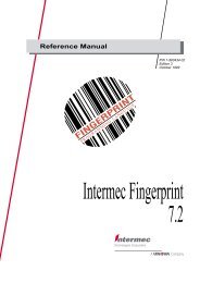
The <strong>9560</strong> <strong>Transaction</strong> <strong>Manager</strong><br />
1-4<br />
The <strong>Intermec</strong> <strong>9560</strong> <strong>Transaction</strong> <strong>Manager</strong> is a stationary online data collection<br />
reader. It collects data from digital input devices, such as a bar code scanner,<br />
and transmits the data to a host device, such as a PC. The following drawing<br />
shows the <strong>9560</strong> in a typical data collection system.<br />
Supervisory CRT<br />
Bar Code Label<br />
9191<br />
Satellite<br />
Wand<br />
Station<br />
Port Concentrator<br />
7 8 9<br />
4 5 6<br />
1 2 3<br />
- .<br />
0<br />
Bksp Space Enter<br />
<strong>9560</strong><br />
F1 F6<br />
F2 F7<br />
F3 F8<br />
F4 F9<br />
F5 F10<br />
<strong>9560</strong><br />
Laser Scanner<br />
<strong>Intermec</strong><br />
A Litton Company<br />
Host Computer<br />
Door Lock<br />
(connects to<br />
Output Relay)<br />
Door Sensor<br />
(connects to<br />
Sense Input)<br />
<strong>9560</strong>-01U<br />
Note: The <strong>9560</strong> is built to withstand constant use in industrial environments, but<br />
improper use can damage it. To avoid problems, please read this manual carefully.
nugget code39 helconital Getting Started<br />
<strong>9560</strong> Component Options<br />
1<br />
The <strong>9560</strong> offers two display options, three keyboard options, and three reader<br />
options. Both displays are LCD displays with an LED backlight. All keyboards<br />
have programmable function keys. You have these basic options for the <strong>9560</strong>:<br />
• 2-line by 40-character display<br />
• 1-line by 20-character oversized display<br />
• Full alphanumeric keypad with tactile feedback<br />
• Numeric/function keypad with tactile feedback<br />
• Numeric/function keypad with large function keys<br />
• Bar code slot scanner<br />
• Magnetic card reader<br />
• No internal reader<br />
You can monitor and control other devices through the three input/output<br />
relays in the <strong>9560</strong>. The sense inputs monitor various events, such as opening<br />
and closing doors. The output relays allow the <strong>9560</strong> to control external devices,<br />
such as door locks.<br />
The following drawing shows the keyboards and displays for the <strong>9560</strong>. Your<br />
version may have any combination of the available options.<br />
2x40<br />
1x20<br />
Code 128<br />
STANDARD<br />
Code 128 STANDARD<br />
Numeric II<br />
Numeric<br />
<strong>9560</strong><br />
<strong>Intermec</strong> <strong>Intermec</strong><br />
A Litton Company<br />
Alphanumeric<br />
<strong>9560</strong>-46U<br />
1-5
<strong>9560</strong> <strong>Transaction</strong> <strong>Manager</strong> User’s <strong>Manual</strong> nugget code39 helconital<br />
1-6<br />
Optional Input Devices<br />
The <strong>9560</strong> accepts input from several sources. The basic configuration includes<br />
either an internal magnetic card reader or an internal slot scanner. The slot<br />
scanner is available in visible or infraredlight models. You can connect any of<br />
the following input devices to the <strong>9560</strong>:<br />
• 1700 Digital Keyboard<br />
• 9191 Digital Satellite Wand Station<br />
• 1260/1270 Series Digital Wands<br />
• 1350 Series Badge Scanners<br />
• 1500/1600 Series Laser Scanners<br />
• RS-232 magnetic stripe reader<br />
• Any asynchronous CRT terminal<br />
• Any asynchronous host computer<br />
Data Formats and Programming<br />
The <strong>9560</strong> can format the data it collects to meet your system’s protocol and<br />
communication requirements. You specify the format by scanning bar code<br />
command labels, downloading command sequences from the host, or selecting<br />
options from menus in the reader’s Prompting Configuration mode.<br />
You can develop custom programs for the <strong>9560</strong> with the Interactive Reader<br />
Language (IRL). IRL provides the flexibility of a high-level language and does<br />
not require a development system. See Chapter 9, “Interactive Reader<br />
Language,” for more information on IRL.<br />
You can store programs in the <strong>9560</strong>’s memory (256K of RAM) or in the host’s<br />
memory to be downloaded to the reader. If the <strong>9560</strong> loses power, a NiCad<br />
battery retains the memory for up to 10 days.<br />
Memory<br />
The <strong>9560</strong> provides 256K of RAM for storing IRL programs and data. The data<br />
may be validation files or collected input, especially if the host cannot receive<br />
data. The maximum memory available is limited as follows:<br />
Type Maximum Size<br />
System overhead 12K<br />
IRL programs 52K<br />
Data (with IRL programs) 182K<br />
Data (no IRL programs) 240K
nugget code39 helconital Getting Started<br />
Bar Code Symbologies<br />
1<br />
The <strong>9560</strong> can automatically discriminate between several bar code symbologies.<br />
You can set the reader to decode any combination of the valid symbologies.<br />
You can save reader memory by enabling only the symbologies required for<br />
your tasks.<br />
The <strong>9560</strong> can decode these bar code symbologies:<br />
• Code 39<br />
• HIBC<br />
• Interleaved 2 of 5 (I 2 of 5; variable length and even, fixed length)<br />
• Code 2 of 5<br />
• Codabar (Standard, American Blood Commission, and Concatenated)<br />
• UPC (including supplemental codes for periodicals)<br />
• EAN<br />
• Code 11<br />
• Code 93<br />
• Code 128<br />
Communications<br />
The <strong>9560</strong> supports RS-232, RS-422, and 4-wire RS-485 multi-drop<br />
communications standards. Current loop can be supported with an external<br />
adapter. Contact your local <strong>Intermec</strong> service supplier for suggested<br />
manufacturers and ordering instructions.<br />
Status Beeps<br />
The <strong>9560</strong> sounds high or low beeps to indicate status conditions. A single beep<br />
means a valid read, a high pitched beep means immediate transmission to the<br />
host, and a low pitched beep means no transmission. For more information on<br />
beep sequences, see “Starting the <strong>9560</strong>” in Chapter 4.<br />
The <strong>9560</strong> standard speaker may not be loud enough in an extremely noisy<br />
environment. You can connect a set of headphones or an external amplifier and<br />
speaker to the audio connector. For more information, see “Attaching Audio<br />
Output Devices” in Chapter 2.<br />
You can attach an external speaker or light to a relay to supplement the<br />
standard speaker. For more information, see “Selecting External Devices” in<br />
Chapter 2.<br />
1-7
nugget code39 helconital<br />
A B C D E Caps<br />
F G H I J $<br />
K L M N O /<br />
P Q R S T<br />
U V W<br />
X Y Z<br />
,<br />
7 8 9<br />
4 5 6<br />
1 2 3<br />
- . 0<br />
Bksp Space Enter<br />
Preparing to Install the <strong>9560</strong><br />
F1 F6<br />
F2 F7<br />
F3 F8<br />
F4 F9<br />
F5 F10<br />
<strong>9560</strong><br />
<strong>Intermec</strong><br />
2
nugget code39 helconital
Preparing to Install the <strong>9560</strong><br />
This chapter contains the background information you need before you install the<br />
<strong>9560</strong>. If you are familiar with the <strong>9560</strong>, you may skip this chapter.<br />
Getting Ready to Install the <strong>9560</strong><br />
2<br />
Once you are familiar with the <strong>9560</strong>, you are ready to plan your system and<br />
how to include the <strong>9560</strong>. The following topics provide the background<br />
information you need:<br />
• Determining a mounting location<br />
• Selecting external devices<br />
• Connecting to a data collection system<br />
• Meeting power supply requirements<br />
If you are already familiar with these topics, skip ahead to Chapter 3,<br />
“Installing the <strong>9560</strong>.”<br />
2-3
<strong>9560</strong> <strong>Transaction</strong> <strong>Manager</strong> User’s <strong>Manual</strong><br />
Determining a Mounting Location<br />
<strong>9560</strong> Mounted on a Wall<br />
2-4<br />
You can mount the <strong>9560</strong> on a horizontal surface, such as a desktop, or on a<br />
vertical surface, such as a wall.<br />
Make sure that the mounting location provides the following:<br />
• Easy access to the internal card reader<br />
• Easy access to all front panel keys<br />
• An unobstructed view of the display<br />
• Clearance for cables and power supply<br />
A B C D E Caps 7 8 9<br />
F G H I J $ 4 5 6<br />
K L M N O / 1 2 3<br />
- .<br />
P Q R S T ,<br />
0<br />
U V W X Y Z<br />
Bksp Space Enter<br />
F1 F6<br />
F2 F7<br />
F3 F8<br />
F4 F9<br />
F5 F10<br />
<strong>9560</strong><br />
<strong>Intermec</strong><br />
A Litton Company<br />
Mount the <strong>9560</strong><br />
right side up as shown.<br />
<strong>9560</strong>-37U<br />
Note: The <strong>9560</strong> is moisture- and dust-resistant only if it is mounted right side up on a<br />
wall or other vertical surface.
Choosing Secured or Unsecured Wiring<br />
Preparing to Install the <strong>9560</strong><br />
2<br />
Before mounting the <strong>9560</strong>, you must choose which type of wiring your system<br />
requires. Secured wiring protects the cables from exposure and requires you to<br />
install the security plate on the <strong>9560</strong>. Unsecured wiring routes the cables into<br />
the room with no extra protection.<br />
Note: To comply with IEC 950, you must install the <strong>9560</strong> near an easily accessible<br />
socket outlet.<br />
Selecting External Devices<br />
You can use many types of external devices with the <strong>9560</strong>.<br />
Choosing Input Devices<br />
You use input devices, such as wands and laser scanners, to provide<br />
information to the <strong>9560</strong>. Input devices can supplement or replace the internal<br />
scanner or card reader included with the <strong>9560</strong>.<br />
This Input Device Connects To<br />
1200 series digital wands Wand (modular) connector<br />
1350 series badge scanners Wand (modular) connector<br />
1500 and 1600 series laser scanners<br />
(with 9-pin D-subminiature connector)<br />
Laser scanner connector<br />
1700 keyboard Wand (modular) connector<br />
9191 digital satellite wand station Wand (modular) connector<br />
Any asynchronous CRT terminal Terminal plug<br />
RS-232 magnetic stripe reader Terminal plug<br />
Any asynchronous host computer Modem socket<br />
Note: If you order the <strong>9560</strong> with the internal slot scanner or magnetic card reader, you<br />
may not need an additional input device.<br />
Attaching Wands and Scanners<br />
You can connect a combination of wands and scanners to the <strong>9560</strong> if you are<br />
certain that you will use only one device at a time. The <strong>9560</strong> uses the same<br />
video line for the internal slot scanner and the external scanners (9191 satellite<br />
wand stations, laser scanners). If you try to scan from any two of these devices<br />
at the same time, the <strong>9560</strong> does not accept any input at all.<br />
2-5
<strong>9560</strong> <strong>Transaction</strong> <strong>Manager</strong> User’s <strong>Manual</strong><br />
2-6<br />
For example, if your system has a 9191 satellite wand station and an internal<br />
slot scanner, you can only scan from one or the other at one time. The <strong>9560</strong><br />
cannot process information from both scanners at the same time.<br />
The internal magnetic card reader does not use the video line and does not<br />
interfere with wands or scanners. You can swipe a magnetic card and scan a<br />
label with a wand at the same time.<br />
Attaching Devices to the Terminal Plug<br />
Use the terminal plug to attach a remote terminal, external magnetic card<br />
reader, or other device to the <strong>9560</strong>. If you order the <strong>9560</strong> with the internal<br />
magnetic card reader, you cannot attach an external device to the terminal<br />
plug. The internal magnetic card reader uses the terminal plug.<br />
Installing the <strong>9560</strong> Without Input Devices<br />
You can install the <strong>9560</strong> without a 1700 keyboard or any other external input<br />
device. If you do, you must start the IRL program before permanently<br />
mounting the unit, or you must start the IRL program from the host. For more<br />
information, see “Creating and Running IRL Programs” in Chapter 9.<br />
Unattended Scanning<br />
You can configure the <strong>9560</strong> to accept input from an unattended laser scanner.<br />
For example, you can mount a laser scanner beside a conveyor line where<br />
boxes with bar code labels pass in front of the scanner. You can set the scanner<br />
to automatically scan when it senses a label. This is called remote triggering.<br />
You either physically set the <strong>9560</strong> for remote triggering, or you can send<br />
software commands to the <strong>9560</strong>.<br />
To physically enable remote triggering<br />
1. Position jumper J17 to short pins 1 and 2.<br />
J17<br />
<strong>9560</strong>-30U<br />
Or, provide an external device that senses when a bar code is waiting to be<br />
read. When triggered, the external device should short pin 11 on either the<br />
modem or terminal port to signal ground (pin 7). Do not use pin 11 on the<br />
unused port.
Preparing to Install the <strong>9560</strong><br />
2<br />
2. Set the <strong>9560</strong> trigger mode to edge and define a scanner timeout. To set these<br />
parameters, see Chapter 6, “Configuring the <strong>9560</strong>,” and Chapter 7,<br />
“Configuration Commands.”<br />
To enable remote triggering with software commands<br />
1. Set the scanner to Auto Trigger mode. See “Enter Auto Trigger Mode” in<br />
Chapter 8.<br />
2. Set the <strong>9560</strong> trigger mode to edge and define a scanner timeout. To set these<br />
parameters, see Chapter 6, “Configuring the <strong>9560</strong>,” and Chapter 7,<br />
“Configuration Commands.”<br />
Note: Remote triggering requires an environment with an electrically clean signal.<br />
Noise or static will disrupt the scanner.<br />
Using the Sense Inputs<br />
The <strong>9560</strong> includes three sense inputs and three output relays. You use the<br />
inputs to monitor events, such as the opening and closing of doors or gates.<br />
For example, you may want the reader to beep if the door open. Each sense<br />
input monitors its line for an input signal within the following range:<br />
• 1 msec minimum duration<br />
• 5V to 24V (AC or DC)<br />
• 10mA to 60mA<br />
You select the voltage range of the input signal by setting a jumper on the<br />
appropriate jumper block. Each sense input is isolated to protect the <strong>9560</strong> from<br />
any damaging currents that may inadvertently enter through the input line.<br />
Voltage Range Jumper Setting<br />
5 to 14 V Pins 1 and 2<br />
14 to 24 V Pins 2 and 3<br />
When a sense input detects a signal, the circuitry is put in a “set” state. The<br />
circuitry remains set until the software reads the status of the sense inputs.<br />
When the <strong>9560</strong> executes an IRL F command, it places the status of the inputs<br />
into the #0 register and resets the circuitry. For more information, see<br />
Chapter 9, “Interactive Reader Language.”<br />
2-7
<strong>9560</strong> <strong>Transaction</strong> <strong>Manager</strong> User’s <strong>Manual</strong><br />
2-8<br />
The status is stored as follows:<br />
• The #0 register contains a 3-digit binary string.<br />
• A 1 indicates a signal has been detected; a 0 indicates no signal.<br />
• The digits correspond to the inputs as shown in the following diagram:<br />
Third input<br />
J3<br />
0 1 1 Register #0<br />
Second input<br />
J2<br />
First input<br />
J1<br />
<strong>9560</strong>-40U<br />
For example, if the #0 register contains 011, it would indicate a signal at the<br />
first and second inputs, but none at the third input.<br />
The following diagram shows a typical connection to a sense input. In this<br />
example, a normally open door sense switch is wired in series with the sense<br />
input and a secondary power circuit. When the door switch is closed, the sense<br />
input detects the 24V output from the power circuit.<br />
Sample Sense Input Application<br />
Input Range Selection<br />
Jumper Block<br />
Terminal<br />
Block<br />
Normally Open Door<br />
Sense Switch<br />
330 1200<br />
1 2 3<br />
1 2 3<br />
Secondary circuit of no<br />
more than 24 VDC or VAC<br />
and no more than 60 mA.<br />
4 5<br />
Optical<br />
Isolator<br />
For 5-14V input, jumper pins 1 and 2.<br />
For 14-24V input, jumper pins 2 and 3.<br />
<strong>9560</strong><br />
External<br />
<strong>9560</strong>-03U
Using the Output Relays<br />
Preparing to Install the <strong>9560</strong><br />
2<br />
The <strong>9560</strong> includes three sense inputs and three single-pole, double-throw<br />
output relays. You use these relays to actuate external devices, such as door or<br />
turnstile locks. Each relay is rated as follows:<br />
• 24V (AC or DC) maximum<br />
• 1A maximum.<br />
You control the relays with the IRL F command command. If you execute a<br />
reset or remove power to the <strong>9560</strong>, the relays turn off. The relays remain off<br />
until the <strong>9560</strong> receives an F command. For more information on the F<br />
command, see Chapter 9, “Interactive Reader Language.”<br />
The following diagram shows the output relays in a typical application.<br />
Sample Output Relay Application<br />
Relay<br />
Terminal<br />
Block 4<br />
1<br />
2<br />
3<br />
Secondary circuit of no<br />
more than 24 VDC or VAC<br />
and no more than 1A.<br />
5<br />
Electric<br />
Door<br />
Opener<br />
<strong>9560</strong><br />
External<br />
Attaching Audio Output Devices<br />
<strong>9560</strong>-05U<br />
The <strong>9560</strong> contains a 0.138 inch (3.5 mm) audio jack for connecting an external<br />
amplifier and speaker or headphones. When you plug a connector into the<br />
audio jack, the internal speaker is disconnected.<br />
2-9
<strong>9560</strong> <strong>Transaction</strong> <strong>Manager</strong> User’s <strong>Manual</strong><br />
Connecting to a Data Collection System<br />
2-10<br />
You can connect the <strong>9560</strong> into a data collection system in one of three ways:<br />
• Connect to a computer only<br />
• Connect to a computer and terminal<br />
• Connect to a port concentrator or system unit with or without a terminal<br />
Before connecting the data collection system, be sure your system meets the<br />
interface requirements listed next.<br />
Cable Interface Requirements<br />
You can connect the <strong>9560</strong> to an RS-232, RS-422, or 4-wire RS-485 multi-drop<br />
interface. The type of cabling depends upon the distance between the <strong>9560</strong> and<br />
the other components of the system, as shown in the following table.<br />
Maximum Distance Preferred Interface<br />
50 feet RS-232<br />
2000 feet RS-485 multi-drop (use only with a 9161A Option 2 multidrop<br />
concentrator or 9154 Line Controller)<br />
4000 feet RS-422<br />
RS-232 is designed for short distances and is generally not used for long data<br />
lines. It can be used successfully over longer distances if there is a “clean”<br />
electrical environment in the building. Because RS-232 connects the two signal<br />
grounds of the units together, any ground noise is coupled directly to the units.<br />
RS-232 cables longer than 50 feet are susceptible to noise and may cause data<br />
transmission problems. To avoid problems with longer RS-232 cables, you can<br />
install modems at each end of the cable. Modems isolate the equipment<br />
grounds from the cable and reduce noise. Follow the modem manufacturer’s<br />
instructions for terminating the cable, and be sure that the modem has<br />
transformer coupling or optical isolation.<br />
RS-422 uses balanced transmission to provide noise immunity. The<br />
transmission is received with a differential receiver, and the receiver signal<br />
ground is not common with the cable.<br />
Note: If you use RS-422 or RS-485 wiring, you must configure the <strong>9560</strong> for the<br />
chosen interface. The default is RS-232.<br />
For information about host protocols and interface considerations, see<br />
Chapter 5, “Data Communications and Operating Options.”
Preparing to Install the <strong>9560</strong><br />
2<br />
The following cable diagrams and connector pin assignments apply to the three<br />
<strong>9560</strong> data collection system choices:<br />
• Computer<br />
• Computer and terminal<br />
• Port concentrator or system control unit with or without a terminal<br />
Null Modem Cable Diagram and Modem Connector Pin Assignments<br />
To Reader To Computer<br />
13 25<br />
1 14<br />
<strong>9560</strong>-07U<br />
The 25-pin null modem cable works with an RS-232 interface only. You will<br />
need to build a custom cable if you are using RS-422 or RS-485. Use the pin<br />
assignments from the following table to build a custom cable for the modem<br />
connector.<br />
Modem Connector Pin Assignments<br />
Interface Pin No. Signal<br />
RS-232 1 Chassis Ground (optional)<br />
RS-422<br />
and<br />
4-wire<br />
RS-485<br />
Direction From<br />
Reader<br />
2 Transmitted Data Outgoing<br />
3 Received Data Incoming<br />
4 Request to Send Outgoing<br />
5 Clear to Send Incoming<br />
7 Signal Ground (required)<br />
20 Data Terminal Ready Outgoing<br />
1<br />
13<br />
14<br />
Chassis Ground (optional)<br />
Received Data B<br />
Transmitted Data A<br />
Incoming<br />
Outgoing<br />
16 Received Data A Incoming<br />
19 Transmitted Data B Outgoing<br />
all 11 Remote Triggering (when enabled)<br />
2-11
<strong>9560</strong> <strong>Transaction</strong> <strong>Manager</strong> User’s <strong>Manual</strong><br />
2-12<br />
Modem Cable Diagram and Terminal Connector Pin Assignments<br />
To Reader To Computer<br />
13 25<br />
1 14<br />
<strong>9560</strong>-07U<br />
The 25-pin modem cable works with an RS-232 interface only. You will need to<br />
build a custom cable if you are using RS-422 or RS-485. Use the pin<br />
assignments from the following table to build a custom cable for the terminal<br />
connector.<br />
Terminal Connector Pin Assignments<br />
Interface Pin No. Signal<br />
RS-232 1 Chassis Ground (optional)<br />
RS-422<br />
and<br />
4-wire<br />
RS-485<br />
Direction From<br />
Reader<br />
2 Transmitted Data Incoming<br />
3 Received Data Outgoing<br />
4 Request to Send Incoming<br />
5 Clear to Send Outgoing<br />
7 Signal Ground (required)<br />
1<br />
13<br />
14<br />
16<br />
19<br />
Chassis Ground (optional)<br />
Received Data B<br />
Transmitted Data A<br />
Received Data A<br />
Transmitted Data B<br />
all 11 Remote Triggering (when enabled)<br />
Outgoing<br />
Incoming<br />
Outgoing<br />
Incoming
Connecting Directly to a Computer<br />
Preparing to Install the <strong>9560</strong><br />
2<br />
You can connect a computer directly to the <strong>9560</strong> modem connector. If the<br />
connector on the computer is a plug (not a socket), then use a socket/socket<br />
adapter cable, such as <strong>Intermec</strong> Part No. 035009S. The <strong>9560</strong> modem connector<br />
is wired as a Data Terminal Equipment (DTE) device.<br />
Connecting to a Computer<br />
Modem Connector<br />
Computer<br />
<strong>9560</strong>-06U<br />
You need a null modem cable, such as <strong>Intermec</strong> Part No. 043069, or any other<br />
null modem cable that meets these standards:<br />
• 4-wire null modem cable<br />
• 10-foot suggested length<br />
• 25-pin D-subminiature connector that is compatible with the computer<br />
• 25-pin, D-subminiature plug connector at one end<br />
Connecting to a Computer and Terminal<br />
If your system includes a computer and a terminal, connect the computer to<br />
the <strong>9560</strong> modem connector first. Use a null modem cable as described in the<br />
previous section, “Connecting Directly to a Computer.”<br />
Next connect the CRT terminal or other ASCII device to the <strong>9560</strong> terminal<br />
connector with a modem cable. The terminal connector is wired as a Data<br />
Communications Equipment (DCE) device.<br />
2-13
<strong>9560</strong> <strong>Transaction</strong> <strong>Manager</strong> User’s <strong>Manual</strong><br />
2-14<br />
Connecting to a Computer and Terminal<br />
CRT Terminal<br />
Terminal Connector<br />
Modem Connector<br />
Computer<br />
<strong>9560</strong>-10U<br />
You need a modem cable, such as <strong>Intermec</strong> cable Part No. 043237S. You can<br />
also use any other modem cable that meets these standards:<br />
• 4-wire modem cable<br />
• 8-foot suggested length<br />
• 25-pin D connector<br />
• Plug connector at one end that is compatible with the terminal<br />
• 25-pin “D” subminiature socket connector at one end<br />
Connecting to a Port Concentrator or System Unit<br />
You can connect one or more <strong>9560</strong>s to a port concentrator or other system unit.<br />
You use direct wiring to connect the <strong>9560</strong> directly to the port concentrator. You<br />
use multi-drop line wiring to connect several <strong>9560</strong>s to the same line and port.<br />
If your system also includes a CRT, connect the CRT cable to the terminal<br />
connector.
Port Concentrator Options<br />
Connecting the <strong>9560</strong> to a Port Concentrator<br />
Preparing to Install the <strong>9560</strong><br />
Modem Connector Modem Connector<br />
Port Concentrator<br />
Connecting the <strong>9560</strong> to a 9154 Line Controller<br />
Modem Connector<br />
9154 Line Controller <strong>9560</strong>-12U<br />
Concentrator Protocol Interface Cable<br />
9161B Option 01 Polling Mode D RS-232 or RS-422 RS-232 cable, <strong>Intermec</strong> Part No. 041789S<br />
RS-422 cable, supplied by customer<br />
9161B Option 02 Polling Mode D<br />
or Multi-Drop<br />
RS-232, RS-422, or<br />
4-wire RS-485<br />
multi-drop<br />
<strong>9560</strong>-11U<br />
2<br />
RS-232 cable, <strong>Intermec</strong> Part No. 041789S<br />
RS-422 cable supplied by customer<br />
RS-485 cable, Part No. 047661<br />
9165A Polling Mode D RS-232 or RS-422 Supplied by customer<br />
9154 Line Controller Multi-Drop 4-wire RS-485 RS-485 cable, <strong>Intermec</strong> Part No. 047661<br />
2-15
<strong>9560</strong> <strong>Transaction</strong> <strong>Manager</strong> User’s <strong>Manual</strong><br />
2-16<br />
Direct Wiring<br />
Direct wiring to a port concentrator requires a cable with the following:<br />
• One connector that is compatible with the port concentrator<br />
• 25-pin, D-subminiature plug connector<br />
The modem connector is wired as a Data Terminal Equipment (DTE) device.<br />
For more information, see “Null Modem Cable Diagram and Modem<br />
Connector Pin Assignments” earlier in this section.<br />
Multi-Drop Line Wiring<br />
You can connect one or more <strong>9560</strong>s to a concentrator using RS-485 multi-drop<br />
line wiring. The multi-drop layout consists of a main line up to 2000 feet long,<br />
as shown in in the following diagram.<br />
Multi-Drop Wiring to a Port Concentrator<br />
Port Concentrator<br />
2000 Ft Max<br />
Device Device Device<br />
30 Ft Max<br />
<strong>9560</strong>-08U<br />
You can connect up to 32 readers, with each a maximum of 20 feet from the<br />
main line. If you use <strong>Intermec</strong> cable Part No. 047653, you can space the readers<br />
up to 30 feet. <strong>Intermec</strong> has tested and approved this layout. Any other multidrop<br />
system layout may not work properly.<br />
For multi-drop wiring, you need a cable that meets these standards:<br />
• 4-wire cable with two individually shielded wire pairs<br />
• One connector that is compatible with the computer<br />
• 25-pin, D-subminiature plug connector<br />
• At least 24-gauge wire<br />
• Nominal impedance ≤ 150 ohms<br />
• Nominal capacitance ≤ 20 pF/ft<br />
• Attenuation ≤ 6 dbv in 2000 feet.
Preparing to Install the <strong>9560</strong><br />
2<br />
<strong>Intermec</strong> recommends using a cable capable of passing the VW-1 vertical flame<br />
test. The following table lists Belden cables that meet these requirements.<br />
Belden Cable Meeting Multi-Drop Requirements<br />
Nominal Nominal<br />
Belden Part VW-1 Test Gauge Impedance Capacitance 6 dbv<br />
9729 No 24 100 12.5 2100<br />
8102 No 24 100 12.5 2100<br />
8162 No 24 100 12.5 2100<br />
82729 UL Listed (60°C) 24 100 12.5 2100<br />
89729 UL Listed (200°C) 24 100 12.5 2100<br />
Note: Belden cable #89729 has the additional feature of being UL listed for use in an air plenum without being in<br />
conduit - NEC Article 725, UL classified, Class 2 Circuits).<br />
You can make open, unshielded, connections between cable sections with heat<br />
shrink or other applied protection. Keep the unshielded section shorter than 2.0<br />
inches (5.08 cm). You do not need a shielded box for connections.<br />
Connect sections to the concentrator or the <strong>9560</strong> at pin 1 of the selected channel,<br />
as shown in the following diagram.<br />
Cable/Connector Diagram for Multi-Drop Wiring<br />
9-Pin D Sub Male<br />
Port Concentrator<br />
Shield<br />
TXDB<br />
TXDA<br />
RXDB<br />
RXDA<br />
1<br />
4<br />
6<br />
8<br />
9<br />
Devices<br />
1<br />
13<br />
16<br />
19<br />
14<br />
GND<br />
RXDB<br />
RXDA<br />
TXDB<br />
TXDA<br />
1<br />
13<br />
16<br />
19<br />
14<br />
GND<br />
RXDB<br />
RXDA<br />
TXDB<br />
TXDA<br />
1<br />
13<br />
16<br />
19<br />
14<br />
GND<br />
RXDB<br />
RXDA<br />
TXDB<br />
TXDA<br />
<strong>9560</strong>-09U<br />
2-17
<strong>9560</strong> <strong>Transaction</strong> <strong>Manager</strong> User’s <strong>Manual</strong><br />
Meeting Power Supply Requirements<br />
2-18<br />
The <strong>9560</strong> contains an internal power supply that automatically adjusts to any<br />
input from 100 to 240 VAC and from 50 to 60 Hz. A standard IEC connector,<br />
located on the chassis and directly below the connector board, accepts various<br />
power cords used throughout the world. To fit properly, a power cord must<br />
have a right-angle connector with a maximum overall height of 1.77 inches (45<br />
mm).<br />
The <strong>9560</strong> is designed to be powered on continuously: there is no power switch.<br />
to remove power from the unit, simply unplug the power cord.<br />
If the reader is configured to resume IRL and the power is disconnected while a<br />
program is running, the program resumes when you restore power.
nugget code39 helconital<br />
A B C D E Caps<br />
F G H I J $<br />
K L M N O /<br />
P Q R S T<br />
U V W<br />
X Y Z<br />
,<br />
7 8 9<br />
4 5 6<br />
1 2 3<br />
- . 0<br />
Bksp Space Enter<br />
F1 F6<br />
F2 F7<br />
Installing the <strong>9560</strong><br />
F3 F8<br />
F4 F9<br />
F5 F10<br />
<strong>9560</strong><br />
<strong>Intermec</strong><br />
3
nugget code39 helconital
Installing the <strong>9560</strong><br />
3<br />
This chapter contains the installation procedures for the <strong>9560</strong>. To properly and safely<br />
install the <strong>9560</strong>, you must read this entire chapter and understand the installation<br />
process.<br />
Overview of Installing the <strong>9560</strong><br />
Before installing the <strong>9560</strong>, make sure that you received all the necessary parts.<br />
Your shipment should include these components:<br />
• <strong>9560</strong> unit and housing<br />
• AC power cord<br />
• Security plate with three screws<br />
• Mounting plate with eight screws.<br />
The following two drawings show the main <strong>9560</strong> components.<br />
<strong>9560</strong> Parts and Their Locations<br />
Housing<br />
Chassis<br />
Security<br />
Plate<br />
Display<br />
Keypad<br />
(Alpha Characters<br />
optional)<br />
A B C D E Caps 7 8 9<br />
F G H I J $ 4 5 6<br />
K L M N O / 1 2 3<br />
- .<br />
P Q R S T ,<br />
0<br />
U V W<br />
Power<br />
Connector<br />
X Y Z<br />
Bksp Space Enter<br />
Connector<br />
PCB<br />
F1 F6<br />
F2 F7<br />
F3 F8<br />
F4 F9<br />
F5 F10<br />
<strong>9560</strong><br />
Mounting<br />
Plate<br />
<strong>Intermec</strong> <strong>Intermec</strong><br />
A Litton Company<br />
Slot<br />
Scanner<br />
<strong>9560</strong>-45U<br />
3-3
<strong>9560</strong> <strong>Transaction</strong> <strong>Manager</strong> User’s <strong>Manual</strong><br />
3-4<br />
WARNING<br />
Connector PCB Parts and Their Locations<br />
Relays<br />
Connector<br />
PCB<br />
Audio<br />
Connector<br />
Sense Jumper<br />
Block<br />
Wand/Slot Scanner<br />
Connector<br />
Terminal<br />
Blocks Laser<br />
Scanner<br />
Connector<br />
Terminal<br />
Connector<br />
Battery<br />
Modem<br />
Connector<br />
Exit IRL<br />
Switch<br />
<strong>9560</strong>-44U<br />
General Installation Steps<br />
Your system requirements determine some of the installation steps. In general,<br />
follow these steps to install the <strong>9560</strong>:<br />
1. Read and follow all warnings and cautions.<br />
2. Turn off the power to the installation area.<br />
3. Route the cables through the mounting plate.<br />
4. Connect the cables for any external devices.<br />
5. Connect the AC power cable. Do not turn on the power.<br />
6. Attach the mounting plate to the housing.<br />
7. Attach the unit to the wall or other surface.<br />
The next sections explain Steps 3 through 7.<br />
Warning<br />
The <strong>9560</strong> uses potentially hazardous AC power. For your safety, you must<br />
understand and follow all safety procedures in this manual and any and all<br />
local building codes. <strong>Intermec</strong> does not assume liability for personal injury,<br />
death, or equipment damage that occurs as a result of your failure to comply<br />
with the installation procedures contained in this manual.<br />
Avertissement<br />
Comme la <strong>9560</strong> utilise le courant AC, qui est potentiellement hazardeux, il est<br />
impératif que vous preniez en considération la sécurité de toutes personnes<br />
installant ou opérant cet équipement. Il faut lire et suivre les avertissements<br />
cidessous. <strong>Intermec</strong> n'assume aucune responsabilité en cas de blessures<br />
personnelles, mort ou endommagement d'équipement dûs à l'inobservation de<br />
l'opérateur des procédures d'installation indiquées dans ce manuel.
WARNING<br />
WARNING<br />
Installing the <strong>9560</strong><br />
3<br />
Warning<br />
When you install the <strong>9560</strong>, you must strictly follow the procedures in this<br />
manual and any and all local building codes. Failure to comply may result in<br />
a hazardous situation.<br />
Avertissement<br />
Il faut réaliser l'installation de la <strong>9560</strong> en suivant strictement les procédures<br />
décrites dans ce manuel ainsi que tout code de construction local, le cas<br />
échéant, faute de quoi vous risquez de provoquer une situation hasardeuse.<br />
Warning<br />
Never open the <strong>9560</strong> by separating the chassis from the housing. Injury or<br />
death can result from the high voltage levels inside.<br />
Avertissement<br />
La <strong>9560</strong> présente un niveau de voltage hasardeux lorsqu'elle est mise sous<br />
tension. Il ne faut jamais l'ouvrir en séparant le cadre du logement, faute de<br />
quoi vous risquez blessures ou mort.<br />
Routing Cables and Power Supply<br />
You can route the cables and power supply in two ways:<br />
• Secured wiring—through the wall into the back of the <strong>9560</strong> with no<br />
exposed wires<br />
• Unsecured wiring—through the hole in the bottom of the <strong>9560</strong> with the<br />
wires exposed to the room<br />
3-5
<strong>9560</strong> <strong>Transaction</strong> <strong>Manager</strong> User’s <strong>Manual</strong><br />
3-6<br />
Routing With Secured Wiring<br />
Use the following drawing as a guide for routing secured wiring in the <strong>9560</strong>.<br />
A B C D E Caps 7 8 9<br />
F G H I J $ 4 5 6<br />
K L M N O / 1 2 3<br />
- .<br />
P Q R S T ,<br />
0<br />
U V W<br />
X Y Z<br />
Mounting<br />
Plate Mounting<br />
Surface<br />
Bksp Space Enter<br />
F1 F6<br />
F2 F7<br />
F3 F8<br />
F4 F9<br />
F5 F10<br />
<strong>9560</strong><br />
<strong>Intermec</strong> <strong>Intermec</strong><br />
A Litton Company<br />
Security<br />
Plate<br />
To route the <strong>9560</strong> with secured wiring<br />
Sealed<br />
Hole<br />
View rotated 180°<br />
<strong>9560</strong>-42U<br />
1. Attach the security plate to the bottom of the housing with the three<br />
screws.<br />
2. Route all wires through a sealed, watertight hole in the mounting surface.<br />
3. Route the wires through the sealing foam in the mounting plate.<br />
4. Connect the wires to the appropriate connector on the <strong>9560</strong>. See<br />
“Connecting External Devices” later in this chapter.<br />
5. After you connect all other devices, connect the power supply cable.
Routing With Unsecured Wiring<br />
Installing the <strong>9560</strong><br />
3<br />
Use the following drawing as a guide to routing unsecured wiring in the <strong>9560</strong>.<br />
A B C D E Caps 7 8 9<br />
F G H I J $ 4 5 6<br />
K L M N O / 1 2 3<br />
- .<br />
P Q R S T ,<br />
0<br />
U V W<br />
X Y Z<br />
Bksp Space Enter<br />
Mounting<br />
Plate<br />
F1 F6<br />
F2 F7<br />
F3 F8<br />
F4 F9<br />
F5 F10<br />
<strong>9560</strong><br />
<strong>Intermec</strong><br />
A Litton Company<br />
To route the <strong>9560</strong> with unsecured wiring<br />
View rotated 180°<br />
Mounting<br />
Surface<br />
<strong>9560</strong>-43U<br />
1. Route the wires through the slot in the bottom of the housing.<br />
2. Route the wires through the sealing foam in the mounting plate.<br />
3. Connect the wires to the appropriate connector on the <strong>9560</strong>. See the next<br />
section, “Connecting External Devices.”<br />
4. After you connect all other devices, connect the power supply cable.<br />
3-7
<strong>9560</strong> <strong>Transaction</strong> <strong>Manager</strong> User’s <strong>Manual</strong><br />
Connecting External Devices<br />
3-8<br />
External devices, such as scanners, laser wands, CRTs, and sense input devices,<br />
connect to the <strong>9560</strong> PCB connector board. The following drawing shows the<br />
connector locations.<br />
Relays<br />
Connector<br />
PCB<br />
Audio<br />
Connector<br />
Sense Jumper<br />
Block<br />
Wand/Slot Scanner<br />
Connector<br />
Terminal<br />
Blocks Laser<br />
Scanner<br />
Connector<br />
Terminal<br />
Connector<br />
Battery<br />
Modem<br />
Connector<br />
Exit IRL<br />
Switch<br />
<strong>9560</strong>-44U<br />
You connect the sense input devices and output relay devices to the terminal<br />
blocks and jumpers as shown.<br />
Sense Input and Output Component Locations<br />
J5<br />
J1<br />
J2<br />
1 2 3 4 5 1 2 3 4 5 1 2 3 4 5<br />
J6<br />
J3<br />
J7<br />
<strong>9560</strong>-04U
Connecting Input Devices<br />
Installing the <strong>9560</strong><br />
Connect the input device to the connector listed in the following table.<br />
Model and Description Connect To<br />
1260 and 1270 Series digital wands Wand (modular) connector<br />
1350 Series badge scanners Wand (modular) connector<br />
1500 and 1600 Series laser scanners<br />
(with 9-pin D-sub connector)<br />
Laser scanner connector<br />
1700 Keyboard Wand (modular) connector<br />
9191 Digital Satellite Wand Station Wand (modular) connector<br />
Any asynchronous CRT terminal Terminal plug<br />
RS-232 magnetic stripe reader Terminal plug<br />
Any asynchronous host computer Modem socket<br />
Connecting to Sense Inputs<br />
3<br />
You use sense inputs to monitor conditions, such as a door opening or closing.<br />
You connect the Sense input lines to terminals 4 and 5 of a terminal block. For<br />
more information, see “Selecting External Devices” in Chapter 2.<br />
Caution<br />
Power to the sense inputs must be from a Class 2 circuit of 5V to 24V, 10mA to<br />
60mA. Never connect main power lines directly to the inputs. Failure to<br />
comply could result in equipment damage.<br />
Conseil<br />
Le courant utilisé par les lecteurs sensoriels doit provenir d'un circuit Classe 2<br />
de 5V - 24V, 10mA - 60mA. Ne connectez jamais les lignes de courant<br />
principales directement aux lecteurs, faute de quoi vous risquez d'endommager<br />
l'équipement.<br />
3-9
<strong>9560</strong> <strong>Transaction</strong> <strong>Manager</strong> User’s <strong>Manual</strong><br />
3-10<br />
To connect to sense inputs<br />
1. Determine the required terminal and jumper blocks, and then set the<br />
jumpers for the sense inputs.<br />
a. Use the following terminal and jumper blocks for each sense input:<br />
Sense Input Terminal Block Jumper Block<br />
1 J1 J5<br />
2 J2 J6<br />
3 J3 J7<br />
b. Set the jumpers for the voltage levels for the sense inputs as follows:<br />
For this voltage Set jumper pins<br />
5V to 14V jumper pins 1 and 2<br />
14V to 24V jumper pins 2 and 3.<br />
2. Connect the external sense input device to posts 4 and 5 of the appropriate<br />
terminal block. The switch mechanism on each device should normally be<br />
open. Use the following diagram as a guide.<br />
Sample Sense Input Application<br />
Input Range Selection<br />
Jumper Block<br />
Terminal<br />
Block<br />
Normally Open Door<br />
Sense Switch<br />
330 1200<br />
1 2 3<br />
1 2 3<br />
Secondary circuit of no<br />
more than 24 VDC or VAC<br />
and no more than 60 mA.<br />
4 5<br />
Optical<br />
Isolator<br />
For 5-14V input, jumper pins 1 and 2.<br />
For 14-24V input, jumper pins 2 and 3.<br />
<strong>9560</strong><br />
External<br />
<strong>9560</strong>-03U
Connecting to Output Relays<br />
Installing the <strong>9560</strong><br />
3<br />
You use the output relays to control external devices, such as an electronic door<br />
lock. You connect output devices to terminals 1, 2, and 3 of a terminal block.<br />
For more information, see “Selecting External Devices” in Chapter 2.<br />
Caution<br />
Power to the external portion of the output relay circuit must be from a<br />
Class 2 circuit providing a maximum of 24V, 1A. Never connect main power<br />
lines directly to the terminal block. Failure to comply could result in<br />
equipment damage.<br />
Conseil<br />
Le courant utilisé par la partie extérieure du circuit de relais en sortie doit<br />
provenir d'un circuit Classe 2 fournissant un maximum de 24V, 1A. Ne<br />
connectez jamais les lignes de courant principales directement au bloc du<br />
terminal, faute de quoi vous risquez d'endommager l'équipement.<br />
To connect output relays<br />
1. Use the following terminal blocks for each output relay:<br />
Output Relay Terminal Block<br />
1 J1<br />
2 J2<br />
3 J3<br />
2. Connect the external devices to the appropriate terminal block.<br />
a. If the device requires a normally closed contact, connect the wires to<br />
posts 1 and 2 on the terminal block.<br />
b. If the device requires a normally open contact, connect the wires to<br />
posts 2 and 3 on terminal block.<br />
3-11
<strong>9560</strong> <strong>Transaction</strong> <strong>Manager</strong> User’s <strong>Manual</strong><br />
3-12<br />
Sample Output Relay Application<br />
Relay<br />
Terminal<br />
Block 4<br />
1<br />
2<br />
3<br />
Secondary circuit of no<br />
more than 24 VDC or VAC<br />
and no more than 1A.<br />
5<br />
Electric<br />
Door<br />
Opener<br />
Connecting Audio Devices<br />
<strong>9560</strong><br />
External<br />
<strong>9560</strong>-05U<br />
You can connect an external amplifier and speaker or a set of headphones to<br />
the <strong>9560</strong>. Connect the cables from the audio device to jumper J12 inside the<br />
<strong>9560</strong>.<br />
Connecting to a Data Collection Host System<br />
Data collection systems vary greatly. For guidelines and system requirements,<br />
see “Connecting to a Data Collection System” in Chapter 2.
Attaching the Mounting Plate<br />
Installing the <strong>9560</strong><br />
After connecting all cables to the <strong>9560</strong>, attach the mounting plate to the<br />
housing. Use the following drawing as a guide.<br />
Attaching the Mounting Plate to <strong>9560</strong> Housing<br />
Mounting<br />
Screws<br />
(3 places)<br />
A B C D E Caps 7 8 9<br />
F G H I J $ 4 5 6<br />
K L M N O / 1 2 3<br />
- .<br />
P Q R S T ,<br />
0<br />
U V W<br />
X Y Z<br />
Mounting<br />
Plate Mounting<br />
Bksp Space Enter<br />
F1 F6<br />
F2 F7<br />
F3 F8<br />
F4 F9<br />
F5 F10<br />
<strong>9560</strong><br />
<strong>Intermec</strong><br />
A Litton Company<br />
Surface<br />
Mounting<br />
Plate Screw<br />
(8 places. Torque<br />
value: 3-4 in/lbs.)<br />
To attach the mounting plate to the housing<br />
<strong>9560</strong>-39U<br />
3<br />
1. Make sure all cabling passes through the sealing foam unbunched and<br />
evenly spaced, as shown below. This routing protects the seal integrity for<br />
secured and unsecured wiring.<br />
2. Fasten the mounting plate over the rear of the <strong>9560</strong> with the eight 6-32<br />
flathead machine screws (Phillips drive). Torque the screws to 3-4 in-lbs<br />
with a torque driver.<br />
3-13
<strong>9560</strong> <strong>Transaction</strong> <strong>Manager</strong> User’s <strong>Manual</strong><br />
3-14<br />
WARNING<br />
Routing Cables through the Sealing Foam<br />
Sealing<br />
Foam<br />
<strong>9560</strong>-32U<br />
Warning<br />
If you need to remove the <strong>9560</strong> mounting plate, first disconnect power to the<br />
unit. Failure to comply could result in injury or death.<br />
Avertissement<br />
Si vous devez enlever la plaque de montage de la <strong>9560</strong>, il faut d'abord coupe le<br />
courant de l'équipement, faute de quoi vous risquez blessures ou mort.
Attaching the <strong>9560</strong> to the Wall<br />
Installing the <strong>9560</strong><br />
3<br />
1. Hold the <strong>9560</strong> to the wall and mark the three screw locations.<br />
2. Set aside the <strong>9560</strong> and predrill the screw holes.<br />
3. Screw the <strong>9560</strong> to the mounting surface with three screws as shown below.<br />
Screw Locations for Attaching the <strong>9560</strong> to the Wall<br />
Mounting<br />
Screws<br />
(3 places)<br />
A B C D E Caps 7 8 9<br />
F G H I J $ 4 5 6<br />
K L M N O / 1 2 3<br />
- .<br />
P Q R S T ,<br />
0<br />
U V W<br />
X Y Z<br />
Mounting<br />
Plate Mounting<br />
Bksp Space Enter<br />
F1 F6<br />
F2 F7<br />
F3 F8<br />
F4 F9<br />
F5 F10<br />
<strong>9560</strong><br />
<strong>Intermec</strong><br />
A Litton Company<br />
Surface<br />
Mounting<br />
Plate Screw<br />
(8 places. Torque<br />
value: 3-4 in/lbs.)<br />
<strong>9560</strong>-39U<br />
3-15
nugget code39 helconital<br />
A B C D E Caps<br />
F G H I J $<br />
K L M N O /<br />
P Q R S T<br />
U V W<br />
X Y Z<br />
,<br />
Starting and Operating the <strong>9560</strong><br />
7 8 9<br />
4 5 6<br />
1 2 3<br />
- . 0<br />
Bksp Space Enter<br />
F1 F6<br />
F2 F7<br />
F3 F8<br />
F4 F9<br />
F5 F10<br />
<strong>9560</strong><br />
<strong>Intermec</strong><br />
4
nugget code39 helconital
Starting the <strong>9560</strong><br />
Operating the <strong>9560</strong><br />
4<br />
This chapter explains how to start the <strong>9560</strong> and how to use the slot scanner, magnetic<br />
card reader, wand, laser scanner, and keypad.<br />
To start the <strong>9560</strong>, you simply plug in the power cord. If the <strong>9560</strong> contains an<br />
IRL program and the unit is configured to resume IRL, that program<br />
automatically runs.<br />
The <strong>9560</strong> beeps to tell you its status while operating. The following table lists<br />
the beeps and their meanings. For a list of the commands that control beeps,<br />
see Chapter 6, “Configuring the <strong>9560</strong>,” and Chapter 7, “Configuration<br />
Commands.”<br />
Beeps Meaning<br />
4 low Power was applied or unit was reset. RAM and ROM are in proper working condition.<br />
High low high An input or output error occurred.<br />
1 low A valid label was read, but not transmitted to the host.<br />
The host sent a BEL character to the <strong>9560</strong>.<br />
An Enter (%+), Backspace (%-), or Space (%/) label was scanned while the <strong>9560</strong> was in<br />
Prompting Configuration mode.<br />
2 low Clear buffer label was read.<br />
3 low Invalid data or an invalid command.<br />
Clear command was sent when the buffer was already empty.<br />
The buffer is full: more than 25 characters in regular operation or 128 characters in<br />
Accumulate mode.<br />
The CAPS key was pressed.<br />
1 high A valid label was read and immediately transmitted to the host.<br />
The host sent a Backslash (\) character to the <strong>9560</strong>.<br />
While in Prompting Configuration mode, data was entered by scanner or wand.<br />
The Enter key was pressed.<br />
A function key was pressed.<br />
Click A keypad character was pressed (other than Caps).<br />
Other sequence The <strong>9560</strong> received a beep sequence command from the host.<br />
Continuous The <strong>9560</strong> was powered up with the magnetic card reader attached and with incorrect<br />
host settings.<br />
4-3
<strong>9560</strong> <strong>Transaction</strong> <strong>Manager</strong> User’s <strong>Manual</strong><br />
4-4<br />
Starting the <strong>9560</strong> With the Magnetic Card Reader<br />
The magnetic card reader requires the <strong>9560</strong> to have specific host<br />
communication settings at power up. If you have not changed the host<br />
settings, you will not have a problem. However, if you change the host settings<br />
and the <strong>9560</strong> loses power, the reader may malfunction.<br />
The internal magnetic card reader requires these host settings at power up:<br />
• 9600 baud<br />
• Even parity<br />
• 7 data bits<br />
• 1 stop bit<br />
If these settings are not correct at power up, the <strong>9560</strong> beeps continually and the<br />
magnetic card reader and the <strong>9560</strong> hang up. Use the following procedure to<br />
correct this problem.<br />
To set the <strong>9560</strong> to use the magnetic card reader on power up<br />
1. Scan each of the following labels, or download the commands from the<br />
host.<br />
Labels Host Commands<br />
9600 Baud<br />
*$+IA6$-*<br />
*$+IA6$-*<br />
Even Parity<br />
*$+IB1$-*<br />
*$+IB1$-*<br />
Data Bits 7<br />
*$+II7$-*<br />
*$+II7$-*<br />
Stop Bits 1<br />
*$+IC1$-*<br />
*$+IC1$-*<br />
$+IA6$-<br />
$+IB1$-<br />
$+II7$-<br />
$+IC1$-<br />
2. Turn off the power to the <strong>9560</strong>, and then turn it on again.
Reading Bar Code Labels<br />
Operating the <strong>9560</strong><br />
4<br />
Bar code labels can contain data or commands. Each label must include start<br />
and stop characters that provide initial timing references and direction of read<br />
information to the coding logic. <strong>Intermec</strong> printers automatically generate<br />
asterisks (*) as the start and stop characters.<br />
Multiple-Read Labels<br />
Multiple-read labels allow several labels to be stored in the reader buffer. The<br />
reader transmits this data only after you scan the Enter label or a label that<br />
does not begin with a space. Multiple-read labels have the format * DATA*,<br />
with a space before the data. A multiple-read label looks like this:<br />
Multiple-Read Label<br />
* DATA*<br />
* DATA*<br />
When you scan a multiple-read label, the reader:<br />
1. sounds one low beep,<br />
2. adds the bar code data (minus the leading space character) to the<br />
transmission buffer,<br />
3. holds the data until receiving the transmit command.<br />
Regular Labels<br />
The reader transmits the data in a regular label as soon as it is scanned. Regular<br />
labels have the format *DATA* with no space before the data. A regular label<br />
looks like this:<br />
Regular Label<br />
*DATA*<br />
*DATA*<br />
When you scan a regular label, the reader:<br />
1. sounds one high beep,<br />
2. adds the label to the data buffer,<br />
3. transmits the data as soon as it is received,<br />
4. clears the data buffer.<br />
4-5
<strong>9560</strong> <strong>Transaction</strong> <strong>Manager</strong> User’s <strong>Manual</strong><br />
Using the Slot Scanner<br />
4-6<br />
You can order the <strong>9560</strong> with an internal infrared or visible light slot scanner.<br />
The slot scanner is always triggered and available for input.<br />
To use the slot scanner, simply slide a bar-coded object (such as an<br />
identification badge, envelope, or file folder) through the slot in either<br />
direction. Make sure that:<br />
• the bar code is placed properly on the object.<br />
• the bar code faces up in the scanner slot as shown.<br />
7 8 9<br />
4 5 6<br />
1 2 3<br />
- .<br />
0<br />
Bksp Space Enter<br />
F1 F6<br />
F2 F7<br />
F3 F8<br />
F4 F9<br />
F5 F10<br />
<strong>9560</strong><br />
<strong>Intermec</strong><br />
A Litton Company<br />
Bar Code Placement<br />
<strong>9560</strong>-49U<br />
The scanning beam must pass through the entire bar code. The beam path is<br />
0.5 in (1.27cm) from the bottom of the scanning slot. For proper scanning, the<br />
bar code must meet the following specifications:<br />
• at least 0.2 in (0.51 cm) tall with a center line 0.5 in (1.27 cm) from the edge<br />
• parallel to the edge of the card or object that passes through the scanner
Using the Magnetic Card Reader<br />
Operating the <strong>9560</strong><br />
4<br />
The <strong>9560</strong> requires an IRL program to use the magnetic card reader. When you<br />
order the <strong>9560</strong> with an internal magnetic card reader, the IRL control program<br />
is already installed on the unit and on a disk.<br />
The magnetic card reader accepts magnetic cards that meet ANSI and ISO<br />
specifications for Track 2. Track 2 only encodes numeric data.<br />
To use the card reader<br />
1. Download the IRL program that controls the card reader to the <strong>9560</strong>. By<br />
default, the program is downloaded at the factory.<br />
2. If you are not using the factory default settings, configure the <strong>9560</strong><br />
communications settings for 9600 baud, 7 data bits, 1 stop bit, and even<br />
parity. See Chapter 7, “Configuration Commands,” or scan this label:<br />
9600 Baud, 7 Data Bits, 1 Stop Bit, Even Parity<br />
*+/$+IA6II7IB1IC1$-*<br />
*+/$+IA6II7IB1IC1$-*<br />
3. Slide a card with a magnetic stripe through the slot, in either direction.<br />
Make sure that the magnetic stripe is facing up towards the top of the unit.<br />
7 8 9<br />
4 5 6<br />
1 2 3<br />
- .<br />
0<br />
Bksp Space Enter<br />
F1 F6<br />
F2 F7<br />
F3 F8<br />
F4 F9<br />
F5 F10<br />
<strong>9560</strong><br />
<strong>Intermec</strong><br />
A Litton Company<br />
Magnetic Strip Reader<br />
<strong>9560</strong>-48U<br />
4-7
<strong>9560</strong> <strong>Transaction</strong> <strong>Manager</strong> User’s <strong>Manual</strong><br />
Using a Wand<br />
4-8<br />
The IRL control program and the magnetic card reader settings are explained<br />
in Chapter 9, “Interactive Reader Language.”<br />
For more information on the magnetic card reader specifications, refer to these<br />
publications:<br />
• ANSI X4.13-1983 Specifications for Credit Cards<br />
• ANSI X4.16-1983 Financial <strong>Transaction</strong> Cards<br />
• ISO 7811/2 THRU 5 Identification Cards Track 1 Thru 3<br />
You can use <strong>Intermec</strong> 1260 and 1270 series digital wands with the <strong>9560</strong>. This<br />
drawing shows how to correctly scan a label with the wand.<br />
*LABEL*<br />
*LABEL*<br />
*LABEL*<br />
*LABEL*<br />
Correct Scanning Procedures<br />
*LABEL*<br />
*LABEL*<br />
Incorrect Scanning Procedures<br />
To scan a label<br />
17°<br />
(Optimum)<br />
*LABEL*<br />
35°<br />
(Maximum)<br />
Optimum Scanning Angle <strong>9560</strong>-15U<br />
1. Place the wand comfortably in your hand, as if it were a pencil, and touch<br />
the tip to the label. Tilt the wand slightly as shown earlier.<br />
2. Place the tip of the wand in the white area at the beginning or end of the<br />
bar code.<br />
3. Using very light pressure, draw an imaginary line through the entire bar<br />
code without stopping. You can scan the bar code in either direction.
Operating the <strong>9560</strong><br />
4<br />
4. Practice using the wand on the following label. Be sure to hold the wand at<br />
a slight angle. Lightly touch the label when scanning.<br />
*LABEL*<br />
*LABEL*<br />
Using a Laser Scanner<br />
WARNING<br />
You can use <strong>Intermec</strong> 1500 and 1600 series laser scanners with the <strong>9560</strong>. Refer<br />
to the documentation supplied with the laser scanner for specific operating<br />
instructions, warnings, and cautions.<br />
Warning<br />
Do not look directly into the window area while the laser is scanning. Long<br />
term exposure to the laser beam can damage vision.<br />
Avertissement<br />
Ne regardez pas directement la région de la fenêtre pendant le passage du laser.<br />
L'exposition à long terme au rayon laser peut endommager la vue.<br />
To scan a label<br />
1. Hold the scanner in the palm of your hand with the index finger resting on<br />
the trigger.<br />
2. Squeeze and hold the trigger to activate the scanner.<br />
3. The spotting beam should fall across all bars and the “quiet zone” at each<br />
end of the label. A quiet zone is a clean, nonprinted space. Use this drawing<br />
as a guide.<br />
Quiet Zone<br />
The scan line must cross<br />
every bar and space<br />
on the symbol.<br />
*LABEL*<br />
Correct<br />
Quiet Zone<br />
*LABEL*<br />
Incorrect <strong>9560</strong>-16U<br />
4-9
<strong>9560</strong> <strong>Transaction</strong> <strong>Manager</strong> User’s <strong>Manual</strong><br />
4-10<br />
4. For best results, do not scan a label straight on. Aim the scanner as shown.<br />
Generally you get the best results with a skew near zero and a pitch near<br />
±20°.<br />
± 2° Dead Zone<br />
where specular<br />
reflection may occur<br />
55°<br />
Skew (Horizontal Reading Angle)<br />
Optimum Scanning<br />
*123*<br />
65°<br />
*123*<br />
Pitch (Vertical Reading Angle)<br />
<strong>9560</strong>-17U<br />
Optimum scanning angles depend upon the type of the label, the distance from<br />
the label, the printing quality, and the lighting of your work area. The<br />
optimum scanning distance from the label to the laser scanner varies with the<br />
type and length of bar code label and the scanning angle. The optimum<br />
distance varies between 3.5 in and 12 in (8.89 cm and 30.48 cm).
Using the Keypad<br />
The <strong>9560</strong> has three keypad options:<br />
• Alphanumeric<br />
• Numeric<br />
• Numeric II, large keys<br />
2x40<br />
1x20<br />
Code 128<br />
STANDARD<br />
Code 128 STANDARD<br />
Numeric II<br />
Operating the <strong>9560</strong><br />
Numeric<br />
<strong>9560</strong><br />
<strong>Intermec</strong><br />
A Litton Company<br />
Alphanumeric<br />
<strong>9560</strong>-46U<br />
4<br />
4-11
<strong>9560</strong> <strong>Transaction</strong> <strong>Manager</strong> User’s <strong>Manual</strong><br />
4-12<br />
Function Key Layout<br />
Each keypad has 10 programmable function keys. The alphanumeric and<br />
numeric/function keypads label the keys F1 through F10. Add your own labels<br />
or use the labels included with the <strong>9560</strong> for custom key names.<br />
The numeric II keypad with the oversized function keys does not label the keys<br />
F1 through F10. The keys do correspond to F1 through F10 as shown in the<br />
following drawing. You can customize the function keys with your own labels<br />
or the labels included with the <strong>9560</strong>.<br />
Layout of Function Keys<br />
F1<br />
F2<br />
F1<br />
F2<br />
F3<br />
F4<br />
F5<br />
F3<br />
F4<br />
F5<br />
F6<br />
F7<br />
F8<br />
F9<br />
F10<br />
F6<br />
F7<br />
F8<br />
F9<br />
F10<br />
Numeric keypad with oversize keys<br />
Alphanumeric and Numeric keypads<br />
<strong>9560</strong>-41U<br />
All keypads ship with replaceable inserts, and the oversize keypad ships with<br />
preprinted labels. You can apply these to meet your applications. You can also<br />
use transfer letters or your own labels. For example, you can print function key<br />
names from your laser printer and cut them to the same size as the insert.
nugget code39 helconital<br />
A B C D E Caps<br />
F G H I J $<br />
K L M N O /<br />
P Q R S T<br />
U V W<br />
Data Communications and Operating Options<br />
X Y Z<br />
,<br />
7 8 9<br />
4 5 6<br />
1 2 3<br />
- . 0<br />
Bksp Space Enter<br />
F1 F6<br />
F2 F7<br />
F3 F8<br />
F4 F9<br />
F5 F10<br />
<strong>9560</strong><br />
<strong>Intermec</strong><br />
5
nugget code39 helconital
Data Communications and Operating Options<br />
5<br />
This chapter provides a general overview of data communications and <strong>9560</strong> operating<br />
options, such as display settings. For more details, refer to <strong>Intermec</strong>’s Data<br />
Communications Reference <strong>Manual</strong>.<br />
Introduction to Data Communications<br />
Your bar code equipment and data processing equipment (the host computer)<br />
must be able to understand and exchange data quickly and accurately. Data<br />
communication standards and protocols spell out exactly how data is to be sent<br />
and received. This section briefly explains the standards and protocols<br />
common to data collection systems.<br />
Data Communications in a Data Collection System<br />
The main purpose of bar code data collection is to get data from the warehouse,<br />
the shop floor, or the factory to a central database quickly where the<br />
information can be processed. To do this, numerous devices transmit and<br />
receive data:<br />
• The host computer sends bar code label formats to a bar code label printer.<br />
• The host computer sends data collection programs through a network<br />
controller to the <strong>9560</strong> and other bar code readers.<br />
• The readers transmit the data collected back to the host computer through a<br />
network controller.<br />
The ISO Data Communications Model<br />
All <strong>Intermec</strong> equipment follows the standards established by the International<br />
Standards Organization (ISO) to describe the data communications process.<br />
The ISO model describes seven, sequential, autonomous layers. For example,<br />
the lowest layer, called the physical layer, describes cable connectors, basic<br />
signaling, and signal levels used in data communications.<br />
The physical layer and the data link layer are the largest layers used by<br />
<strong>Intermec</strong> equipment. For more information on the ISO model and other layers,<br />
refer to <strong>Intermec</strong>’s Data Communications Reference <strong>Manual</strong>.<br />
5-3
<strong>9560</strong> <strong>Transaction</strong> <strong>Manager</strong> User’s <strong>Manual</strong><br />
5-4<br />
Physical Layer<br />
The physical layer describes the hardware components of data transmission. It<br />
sets standards for transmitting voltages and electrical pulses through cables,<br />
connectors, and components. Data transmission at the physical layer is defined<br />
in these three areas:<br />
• Full-duplex or half-duplex transmission<br />
• Parallel or serial transmission<br />
• Asynchronous or synchronous transmission<br />
Half-duplex Transmits and receives data over a single channel, but in one<br />
direction at a time.<br />
Full-duplex Transmits and receives data simultaneously over two separate<br />
channels within the cable.<br />
Parallel transmission Sends several data bits across the interface together.<br />
A group of bits moves over several lines at the same time.<br />
Serial transmission Sends data one bit at a time as a series of pulses. Pulses are<br />
received in a mark (binary 1), or space (binary 0) condition. The speed of the<br />
serial transmission is the baud rate or BPS (bits per second).<br />
You use parallel transmission when the bar code equipment and computers are<br />
located within a few feet of each other. Parallel transmission is much faster<br />
than serial. However, as data lines get longer, noise and interference on the<br />
data lines increase.<br />
Asynchronous transmission Requires a start bit to mark the beginning of a data<br />
block and a stop bit to mark the end of the data block.<br />
Synchronous transmission Uses a clock to determine the exact sending or<br />
receiving time for each bit. More than one data character can be sent per frame,<br />
and start and stop characters are not included.<br />
Several different interface cables and connectors meet the standards for the<br />
physical layer. Each has its own strengths and limitations, depending on the<br />
distances between connected devices and the configuration of the equipment.<br />
The <strong>9560</strong> supports RS-232, RS-422, and RS-485 multi-drop interfaces. For more<br />
information, see Chapter 2, “Preparing to Install the <strong>9560</strong>.”<br />
Data Link Layer<br />
The data link layer deals with the recognition of data received and the<br />
formatting of data transmitted. Protocols guarantee the control and integrity of<br />
messages between both ends of a communication link. Communication at this<br />
layer is either asynchronous or synchronous.
Data Communications and Operating Options<br />
5<br />
Asynchronous protocols at this level perform error detection. For synchronous<br />
protocols, this layer detects starting and ending flags and generates a cyclical<br />
redundancy check (CRC). This layer also identifies whether the transmission<br />
channel is dedicated (point-to-point) or shared (multipoint), and if transmission<br />
is full- or half-duplex.<br />
Full-Duplex Protocols Versus Half-Duplex Protocols<br />
At the data link layer, protocols are described as either full-duplex or halfduplex.<br />
A full-duplex protocol allows messages to be received and transmitted<br />
simultaneously. Your system must have separate, dedicated channels for<br />
receiving and transmitting data to use a full-duplex protocol. Also, the host<br />
and reader must have the necessary hardware (interrupt structure) to support<br />
receiving and transmitting data simultaneously. You define a full-duplex<br />
protocol by disabling both the solicitation sequence (Poll and Select) and<br />
AFF/NEG handshakes.<br />
Point-to-Point and similar user-defined protocols are the only <strong>Intermec</strong><br />
protocols that are full-duplex. These protocols do not support retransmission of<br />
data messages. The reader transmits data when commanded to by the<br />
operator, but the reader receives data from the host at any time.<br />
A half-duplex protocol requires that only one device transmit data at a time<br />
over a shared or dedicated channel. You can use a half-duplex protocol over a<br />
full-duplex medium, but only one device at a time can transmit data. You<br />
define a half-duplex protocol by defining either the POL character or the<br />
AFF character.<br />
Full-Duplex Devices Versus Half-Duplex Devices<br />
Devices are full-duplex or half-duplex depending on their ability to receive and<br />
transmit data simultaneously. Both hardware and software design determine if<br />
a device is full or half-duplex. A full-duplex design requires a hardware UART<br />
(universal asynchronous receiver/transmitter) with double-buffered transmit<br />
and receive buffers. The UART signals the CPU when a character is received or<br />
when the transmit buffer is ready for another character. The software must<br />
perform the transmit or receive functions when the UART signals the CPU<br />
with an interrupt.<br />
The DLE Character and XON/XOFF Flow Control<br />
You use the DLE (data link escape) character to send protocol commands or<br />
parameters that you want to be treated as data. The DLE must precede the<br />
transparent command or parameter. The following protocol parameters are<br />
considered transparent if DLE is enabled: RES, REQ, SOM, TX EOM1,<br />
TX EOM2, and XON/XOFF.<br />
You can send the DLE, EOR (end of record), and EOF (end of file) characters as<br />
data if each is preceded by an DLE.<br />
5-5
<strong>9560</strong> <strong>Transaction</strong> <strong>Manager</strong> User’s <strong>Manual</strong><br />
Working With Protocols<br />
5-6<br />
The XON or the XOFF character may match the LRC (Longitudinal<br />
Redundancy Check character). If so, the LRC is never checked for<br />
transparency. It is always treated as a parameter.<br />
Received data is also checked for a DLE. The XON or XOFF character is<br />
interpreted as data if XON/XOFF flow control is enabled and the character is<br />
preceded by a DLE. In User-Defined protocol, the reader allows flow control to<br />
be implemented along with an LRC. The reader knows when the LRC character<br />
is expected. It does not perform the XON or XOFF character check when the<br />
LRC is the next character expected.<br />
Data link protocols govern the way data is transmitted. They provide the<br />
framework for an orderly exchange of data between computers, terminals, and<br />
data collection devices. With most protocols, the reader (slave) never<br />
communicates unless the host (master) initiates the transaction with a<br />
poll/select sequence. Point-to-Point protocol is the exception.<br />
Polling Mode D and Multi-Drop are very secure data link protocols designed<br />
to interface with the <strong>Intermec</strong> 9154 Network Controller and 9161 Port<br />
Concentrator. Both devices continuously poll bar code readers and printers for<br />
transactions and pass those transactions to the host computer.<br />
Both Polling Mode D and Multi-Drop provide recovery from transmission<br />
errors (parity and framing errors) and use affirmative and negative responses<br />
to verify successful and unsuccessful communication events. If the transmitting<br />
device receives a negative acknowledgment, the data is retransmitted.<br />
You use User-Defined and User-Defined Multi-Drop protocols to develop a<br />
custom protocol. You can define how secure the data link protocol will be and<br />
implement a master/slave data link with error recovery.<br />
Point-to-Point Protocol<br />
Point-to-Point protocol is designed specifically for <strong>Intermec</strong> readers where the<br />
reader is connected to a terminal or a host computer. Point-to-Point protocol<br />
has the following characteristics:<br />
Full-duplex This protocol can send and receive data simultaneously.<br />
Asynchronous The data is sent one character at a time.<br />
Nonpolling The solicitation (POL) and handshake sequences (XON/XOFF) are<br />
disabled.<br />
Whenever data is available to transmit, the data is transmitted immediately.<br />
You can control the flow of data by enabling XON/XOFF or by sending the<br />
CTS command (Clear to Send) from the host.
Data Communications and Operating Options<br />
Point-to-Point accepts and then transmits all data to the host when either:<br />
• the reader receives the EOM character.<br />
• the timeout delay limit is reached.<br />
Polling Mode D Protocol<br />
5<br />
Polling Mode D protocol is a proprietary <strong>Intermec</strong> block transfer protocol. It<br />
works in a Point-to-Point environment and supports only one polled device on<br />
the line. Polling Mode D protocol has these characteristics:<br />
Half-duplex This protocol can send or receive data at one time.<br />
Asynchronous The data is sent one character at a time.<br />
Solicited The solicitation (POL) and handshake sequences (XON/XOFF) are<br />
enabled and required.<br />
Error checking The data block includes the LRC for data integrity.<br />
You can set the Terminal Port mode for either transparent or buffered<br />
operation. The default is buffered. See “Displaying Data on a Terminal” later in<br />
this chapter for descriptions of transparent and buffered operation.<br />
If you are connecting the reader to a host computer, you may need to know the<br />
details of Polling Mode D. However, if you are using an <strong>Intermec</strong> concentrator,<br />
you do not need to understand Polling Mode D. These <strong>Intermec</strong> concentrators<br />
use Polling Mode D protocol:<br />
• 9160 with Rev. C software or higher<br />
• 9160A and 9161B (Options 01 and 02)<br />
• 9165 System Control Unit<br />
Multi-Drop Protocol<br />
You use Multi-Drop protocol in a data communications network where several<br />
devices are connected to a common line. It is designed to work in an<br />
RS-422/RS-485 environment with up to 32 devices on a single multi-drop<br />
transmission line.<br />
Multi-Drop protocol has the following characteristics:<br />
Half-duplex This protocol can send or receive data at one time.<br />
Asynchronous The data is sent one character at a time.<br />
Solicited The solicitation (POL) and handshake sequences (XON/XOFF) are<br />
enabled and required.<br />
The 9154A and the 9161B Option 02 <strong>Intermec</strong> controllers support Multi-Drop<br />
protocol.<br />
5-7
<strong>9560</strong> <strong>Transaction</strong> <strong>Manager</strong> User’s <strong>Manual</strong><br />
5-8<br />
User-Defined and User-Defined Multi-Drop Protocols<br />
You define all protocol parameters in User-Defined protocols. Thus, you can<br />
duplicate any protocol to emulate a proprietary or irregular protocol on a host<br />
computer.<br />
Some protocols are very robust and secure, while others are not. A secure data<br />
link protocol can recover from transmission line errors (parity and framing<br />
errors) and uses affirmative and negative responses to verify communication<br />
events. If the transmitting device receives a negative acknowledgment, the data<br />
is retransmitted. The maximum retry count is three for all asynchronous<br />
<strong>Intermec</strong> protocols.<br />
Tips for Defining Secure Protocols<br />
Use these tips for defining secure User-Defined protocols:<br />
1. Define all protocol fields with ASCII control characters. See the Glossary for<br />
definitions of unfamiliar acronyms and terms. Examples:<br />
SOM = STX REQ = ENQ<br />
AFF = ACK RES = EOT<br />
NEG = NAK EOR1 = RS<br />
EOM1 = ETX EOF = ETB<br />
2. Use even or odd parity when transmitting data.<br />
3. Enable the LRC (Longitudinal Redundancy Check character) to provide<br />
added data security to all transmitted and received messages. When both<br />
parity and LRC checks are enabled, horizontal and vertical error checking<br />
are performed. If the SOM is enabled, it is not included in the LRC<br />
calculation. The reader allows the LRC to be enabled in addition to<br />
XON/XOFF flow control. The host device must also be able to receive the<br />
XON or XOFF character as the LRC or receive the XON or XOFF characters<br />
as data if preceded by the DLE.<br />
4. If the host device cannot guarantee reception of data at all times, the host<br />
should control the transmission of data from the reader. There are three<br />
methods available. Use one of the methods or combine them:<br />
a. Enable Solicitation. This prohibits the reader from sending any type of<br />
data or response unless the host is ready for it.<br />
b. Enable XON/XOFF flow control.<br />
c. Use CTS (clear to send) hardware handshake. The reader checks CTS<br />
before transmitting all characters with the exception of XON/XOFF<br />
responses. If CTS is false, the reader either stops or does not start<br />
transmitting data.<br />
5. Always enable the SOM.
Data Communications and Operating Options<br />
5<br />
6. If the REQ is enabled, also enable the RES. When the REQ is enabled, the<br />
reader waits for the timeout period to expire and then accepts the data. By<br />
enabling the RES, the host sends the RES when it recognizes the response<br />
(AFF) sent by the reader if the data was correctly received.<br />
Buffering Received Data<br />
The <strong>9560</strong> uses three different circular queues to hold received data.<br />
20-byte queue Buffers all characters received. This queue serves as a buffer if<br />
the data cannot be processed as fast as it is received. If XON/XOFF flow<br />
control is enabled, the device transmits the XOFF character when the queue is<br />
half full.<br />
512-byte queue Buffers data characters only. When the data queue has 32 bytes<br />
remaining, the reader sends the XOFF character to the host.<br />
Packet queue Contains a pointer to the packet start position and a byte count.<br />
This information is used to pass complete packets of successfully received<br />
messages to the operating system. The packet queue holds up to 20 packets.<br />
The device sends the XOFF character when the queue has 18 packets.<br />
Communications Delays<br />
While receiving data, the reader waits a specific time before sending an error<br />
message. You can modify this time in Point-to-Point or User-Defined protocols.<br />
Intercharacter delay The amount of time the reader waits before sending each<br />
character to the host. This delay modifies the outgoing transmission rate only.<br />
Use the intercharacter delay when communicating with a controller through<br />
modems in full-duplex operation.<br />
Timeout The amount of time the reader waits between receiving each character<br />
before sending an error message. Also, it is the amount of time the reader waits<br />
for an acknowledgment from the host before sending an error message.<br />
Turnaround delay The amount of time the reader waits after receiving data<br />
before sending a response to the host.<br />
5-9
<strong>9560</strong> <strong>Transaction</strong> <strong>Manager</strong> User’s <strong>Manual</strong><br />
Data Format Requirements<br />
5-10<br />
Regardless of the protocol you selected, the host and the reader must format<br />
the data before transmitting it. Each transmission includes a start character, the<br />
data block, and an end character. The SOM (start of message) character and the<br />
EOM (end of message) character are determined by the protocol. The data<br />
block may include preambles, data, and a postamble.<br />
The following figure shows the data format parameters. The <strong>Intermec</strong> Data<br />
Communications Reference <strong>Manual</strong> describes these parameters in detail.<br />
SOM Preamble Record Postamble EOM(s)<br />
Data Block<br />
SOM Character (Start of Message)<br />
The SOM character precedes the data and indicates the beginning of a data<br />
block. The SOM character is a protocol character and is not part of the data<br />
format.<br />
Preambles and Postambles<br />
The preamble is a field of data sent before record data and a postamble is sent<br />
after record data. Preambles and postambles are typically used to tag<br />
transactions for rapid processing by the host computer. They are also used to<br />
expand the data field (record) length. The reader has two preambles,<br />
Preamble A and Preamble B, and one postamble, Postamble C.<br />
If you select “Preamble A Required” in Configuration mode, you must also<br />
define Preamble A. For preamble commands, see Chapter 8, “Data Entry<br />
Commands.” Your preamble definition is erased if you reset the reader to the<br />
default settings. You will need to re-enter the preamble to use it again.<br />
When the reader transmits a message block, the presentation control first<br />
checks to see if the preamble or postamble functions are enabled and defined.<br />
If they are, then the transmitted data has the following format:<br />
message block <br />
The message may consist of a single record or multiple records. If a file is being<br />
transmitted with multiple records per message block, the message block has<br />
the following format:<br />
record record record last record
Data Communications and Operating Options<br />
• The EOF (End of File) is only transmitted after the last record of a file.<br />
• Time is never appended to the transmitted files.<br />
Preambles and the postamble are described more completely in Chapter 8,<br />
“Data Entry Commands.”<br />
EOR Characters (End of Record)<br />
5<br />
Your destination for the data from the <strong>9560</strong> may require an end of record<br />
character in the data files. If you enable EOR, the reader adds the EOR<br />
character at the end of all the individual records within the file. EOR is disabled<br />
in Polling Mode D, Multi-Drop, and Point-to-Point protocols.<br />
EOF Characters (End of File)<br />
Your destination for the data from the <strong>9560</strong> may require an end of file character<br />
in the data file. The EOF character follows the last record transmitted within<br />
any record block, regardless of the size of the record block. If you enable EOF,<br />
the reader adds the EOF character after the last EOR character (if EOR is<br />
enabled).<br />
EOF is disabled in Point-to-Point protocol. The default EOF character in Polling<br />
Mode D and Multi-Drop protocols is SOH.<br />
Record<br />
A record is a maximum of 128 data characters that can be stored in the reader’s<br />
memory. A record can be:<br />
• Data from a regular label<br />
• Data from several multiple-read labels<br />
• Data from regular or multiple-read labels when the reader is in Accumulate mode<br />
• Data entered from a 1700 keyboard or terminal keyboard<br />
Records per Block<br />
For all protocols except User-Defined protocol, the number of Records per<br />
Block is one. You can set Records per Block from 0 to 99 in User-Defined<br />
protocol. Setting this value to zero transmits the whole file within a single<br />
block.<br />
5-11
<strong>9560</strong> <strong>Transaction</strong> <strong>Manager</strong> User’s <strong>Manual</strong><br />
5-12<br />
EOM Characters (End of Message)<br />
The EOM character follows the data and indicates the end of a data block. The<br />
EOM character is a protocol character and is not part of the data format. The<br />
<strong>9560</strong> can transmit one or two EOM characters.<br />
If you use NUL for the first EOM character, the reader transmits the ASCII<br />
NUL character (00 Hex) and disables communications from the host. If you<br />
enter NUL for the second EOM character, the reader disables the second<br />
character and transmits nothing for the character. The characters cannot be the<br />
same, unless both are NUL.<br />
Error Checking<br />
In User-Defined protocol, the reader can add a Longitudinal Redundancy<br />
Check (LRC) character to data transmissions. The host must have software to<br />
handle the LRC.<br />
The LRC character is the exclusive “OR” of the seven (or eight) data bits in the<br />
data block. The LRC character is the last character sent, but it is not part of the<br />
data. For more detailed information, refer to the Data Communications Reference<br />
<strong>Manual</strong>.<br />
Displaying Data on the <strong>9560</strong><br />
The <strong>9560</strong> has either a 2-line by 40-character standard display or a 1-line by<br />
20-character oversize display. You can scroll the standard display back two<br />
lines. You can scroll the oversize display back three lines, one line at a time.<br />
Note: The keypad on the <strong>9560</strong> does not provide keys for scrolling. You must use an<br />
IRL program, scan bar code command labels, or use the arrow keys on the 1700<br />
keyboard to scroll the display.<br />
Types of Data Displayed<br />
The reader distinguishes between four data types for the display:<br />
Input data All data entered from the keyboard or an input device. This includes<br />
IRL program statements being entered and displayed in the editor.<br />
Host messages Any message received from the host at the reader modem port<br />
with the correct protocol. Host messages can interrupt the current display at<br />
any time.<br />
Reader prompts All messages to the operator, such as those that occur during<br />
Prompting Configuration, with the exception of those messages that describe<br />
errors. This also includes IRL prompt statements when an IRL program is<br />
running.
Data Communications and Operating Options<br />
5<br />
Reader warning messages All error or warning messages to the operator. These<br />
messages can interrupt the current display at any time and are generally<br />
accompanied by a beep. If transparent display is selected, the error messages<br />
are not displayed.<br />
Display Settings and Formatting<br />
The reader has two display settings: buffered and transparent.<br />
Buffered Display<br />
In buffered display mode, the reader adds and executes a CR LF sequence to<br />
all transmitted, received, or scanned data or messages. The CR LF formats the<br />
reader display to show each record, message, or prompt on a new line.<br />
After displaying a host message, the reader adds a CR LF sequence is to any<br />
accumulated data. The CR LF is then executed and any buffered accumulated<br />
data is displayed again on the next display operation.<br />
Transparent Display<br />
In transparent display mode the display does not format data or host messages<br />
with CR LF sequences. You use control codes or control sequences in host<br />
messages or IRL prompts to format data for the display.<br />
Formatting the Display<br />
You use control codes to position the cursor or format the reader display. The<br />
reader recognizes these display control codes:<br />
Description Code Action<br />
Backspace BS (08 Hex) Moves the cursor one position to the left until the cursor reaches<br />
the first column. Except when in the first row, the cursor moves<br />
from the first column of the current row to the last column of<br />
the previous row.<br />
Home CR (0D Hex) Returns the cursor to the first column of the current row.<br />
Next line LF (0A Hex) Moves the cursor down one row in the current column position.<br />
If the cursor is already in the last row, a new line is added.<br />
Erase Display ESC[2J Erases all of the display and returns the cursor to the home<br />
position (row 1, column 1). Erases the entire virtual display<br />
image (buffer with up to four rows of the most recently<br />
displayed data).<br />
5-13
<strong>9560</strong> <strong>Transaction</strong> <strong>Manager</strong> User’s <strong>Manual</strong><br />
Description Code Action<br />
Cursor Position ESC[#;#H Moves the cursor to the position specified by the # parameters.<br />
The first parameter specifies the row or line number and the<br />
second parameter specifies the column number. If zero or no<br />
parameter is entered, the parameter is set equal to one.<br />
Parameters exceeding the maximum row or column number are<br />
set equal to the display’s maximum.<br />
Save Cursor<br />
Position<br />
Restore Cursor<br />
Position<br />
Select Character<br />
Set<br />
Restore<br />
Configured<br />
Character Set<br />
5-14<br />
ESC[s Saves the current cursor position. Successive Save Cursor<br />
Position commands overwrite previous positions saved.<br />
ESC[u Restores the cursor position saved with a Save Cursor Position<br />
command. Each Restore Cursor Position command must be<br />
paired with a preceding Save Cursor Position command. If a<br />
Save Cursor Position command has not been previously issued,<br />
the cursor position remains unchanged<br />
ESC[#w Defines the character set to be used (character sets are defined<br />
later in this chapter). The character set to be used is specified by<br />
the # parameter.<br />
ESC[x Returns the display to the character set defined during<br />
configuration.<br />
Display Overflow<br />
The reader can receive more data than it can display at one time. The display<br />
overflow is stored in the virtual display image buffer of the reader. This buffer<br />
holds up to four rows of the most recently displayed.<br />
The reader display is a window or viewport into the virtual display image. The<br />
2-line by 40-character display shows the last two rows by default. The 1-line by<br />
20-character display shows the last row by default.<br />
You use the review and forward commands to move the display up or down in<br />
the current virtual display image. When you scroll the display up, the cursor is<br />
disabled. When you scroll the display back to the default position in the virtual<br />
display image, the cursor is restored.<br />
Any event that alters the display returns the display to the default position. For<br />
example, entered data, accumulated data, or commands (such as Enter,<br />
Backspace, Clear, or End Accumulate) automatically return the display to the<br />
default position.
Data Communications and Operating Options<br />
Use these commands to modify the virtual display:<br />
Command Result<br />
Review Moves the display up one row in the current virtual display<br />
image if a display control sequence was executed.<br />
5<br />
Forward Moves the display image down one row in the current virtual<br />
display image following a review command.<br />
Backspace Can cause the default display position to be moved up one row<br />
in the current virtual display image if (1) display overflow has<br />
occurred since the last erase display control sequence, and (2)<br />
the command is executed with the cursor in the first column of<br />
the last display row.<br />
Clear Executes multiple backspaces. Can also cause the default<br />
display position to be moved up one or more rows in the<br />
current virtual display image.<br />
Displaying ASCII Control Codes<br />
The reader uses a center dot to display ASCII control code characters such as<br />
CR LF. The center dot is a unique programmed character distinguishable from<br />
all other ASCII characters.<br />
The reader displays prompting configuration and IRL display control<br />
characters as a sequence of characters that can be displayed. Two to five<br />
characters can be used to display one control code. For example, the line feed<br />
control code could be displayed as or LF.<br />
Displaying Data on a Terminal<br />
When you connect the <strong>9560</strong> to a CRT terminal, you need to set the type of<br />
terminal operation. Typically, you set the display to match the reader’s<br />
terminal setting. Your choices as are follows:<br />
• Buffered (default)<br />
• Transparent<br />
• Nonbuffered, full-duplex<br />
• Nonbuffered, half-duplex<br />
• Block<br />
5-15
<strong>9560</strong> <strong>Transaction</strong> <strong>Manager</strong> User’s <strong>Manual</strong><br />
5-16<br />
This table lists valid reader settings for the terminal and reader.<br />
Terminal Screen Formatting Reader Setting Protocol Choices<br />
Reader formats terminal screen Buffered Point-to-Point<br />
User-Defined<br />
User-Defined<br />
Multi-Drop<br />
Polling Mode D<br />
Multi-Drop<br />
Host formats terminal screen Transparent Point-to-Point<br />
User-Defined<br />
User-Defined<br />
Multi-Drop<br />
Polling Mode D<br />
Multi-Drop<br />
Host formats terminal screen,<br />
and uses full-duplex<br />
Host formats the terminal screen,<br />
and uses half-duplex<br />
“Smart” terminal that can buffer several<br />
blocks of data<br />
Buffered Terminal Operation<br />
Nonbuffered, full-duplex Point-to-Point<br />
User-Defined<br />
Nonbuffered, half-duplex Point-to-Point<br />
User-Defined<br />
Block operation Point-to-Point<br />
User-Defined<br />
In buffered operation, the reader is usually connected to a port concentrator<br />
through the modem port and to the terminal through the terminal port. The<br />
reader emulates a smart terminal for batching transmissions to the host.<br />
The reader buffers data from both the terminal and scanner, and then formats<br />
and displays that data on the terminal screen. The reader echoes input from the<br />
terminal until you send a command to transmit the data. The reader transmits<br />
the data to the host when one of these events occurs:<br />
• The reader receives a Transmit command.<br />
• The reader scans a regular label.<br />
• You press Enter from the terminal keyboard.<br />
You can use host control characters to format the terminal screen and display<br />
messages from the host. The terminal also displays communication<br />
diagnostics.
Data Communications and Operating Options<br />
If a host message interrupts a data transmission, the reader:<br />
1. Sends a carriage return line feed (CR LF) to the terminal<br />
2. Displays the host message on the terminal<br />
3. Sends a CR LF to the terminal<br />
4. Displays the entire contents of the preamble and data buffers on the<br />
terminal<br />
Use one of these protocols when the terminal is in full-duplex:<br />
• Point-to-Point<br />
• Polling Mode D<br />
• Multi-Drop<br />
• User-Defined<br />
Although you can configure the terminal in half-duplex, <strong>Intermec</strong> does not<br />
recommend it.<br />
Transparent Terminal Operation<br />
5<br />
When the terminal is set to transparent operation, the host formats the terminal<br />
screen and the terminal does not display diagnostic messages. The reader<br />
accepts limited commands from the terminal.<br />
The reader buffers data from both the terminal and scanner and displays the<br />
unformatted data on the terminal screen. The reader transmits the data to the<br />
host when one of these events occurs:<br />
• The reader receives a Transmit command.<br />
• The reader scans a regular label.<br />
• You press Enter from the terminal keyboard.<br />
Use one of these protocols when the terminal is in full-duplex:<br />
• Point-to-Point<br />
• Polling Mode D<br />
• Multi-Drop<br />
• User-Defined<br />
Although you can configure the terminal in half-duplex, <strong>Intermec</strong> does not<br />
recommend it.<br />
5-17
<strong>9560</strong> <strong>Transaction</strong> <strong>Manager</strong> User’s <strong>Manual</strong><br />
5-18<br />
Nonbuffered Full-Duplex Operation<br />
In nonbuffered, full-duplex operation, the reader does not buffer, format, or<br />
display the data. The reader sends all terminal port input out the modem port<br />
as the data is received. The host echoes all received data, and formats and<br />
sends the data for displaying on the terminal screen. The reader does not<br />
accept terminal commands.<br />
Use one of these protocols when the terminal is in nonbuffered, full-duplex<br />
mode:<br />
• Point-to-Point<br />
• User-Defined<br />
Although you can configure the terminal in half-duplex, <strong>Intermec</strong> does not<br />
recommend it.<br />
Nonbuffered Half-Duplex Operation<br />
In nonbuffered half-duplex operation, the host formats the terminal screen. The<br />
reader transmits data to the host and the terminal screen simultaneously. The<br />
reader does not buffer or format data from the terminal or scanner, but<br />
displays and updates the current data buffer on the terminal screen.<br />
The host must also be set for half-duplex operation and does not echo the<br />
terminal or reader data. The reader sends host messages directly to the<br />
terminal without formatting, and the reader does not accept terminal<br />
commands.<br />
Although you can configure the terminal in full-duplex, <strong>Intermec</strong> does not<br />
recommend it.<br />
Use one of these protocols when the terminal is in nonbuffered, half-duplex<br />
mode:<br />
• Point-to-Point<br />
• User-Defined<br />
Block Terminal Operation<br />
Block terminal operation is generally used with “smart” terminals that can<br />
buffer data. The reader does not buffer, format, or display data from the<br />
terminal but sends this data directly out the modem port to the host.<br />
The reader sends scanned data directly to the terminal through the terminal<br />
port to accumulate in the terminal buffer. The reader does not accept terminal<br />
commands.
Data Communications and Operating Options<br />
5<br />
You must set the host for half-duplex operation. The reader does not format<br />
messages from the host, but displays host messages directly on the terminal<br />
screen.<br />
Although you can configure the terminal in full-duplex, <strong>Intermec</strong> does not<br />
recommend it.<br />
Use one of these protocols when the terminal is in half-duplex mode:<br />
• Point-to-Point<br />
• User-Defined<br />
Displaying International Character Sets<br />
The <strong>9560</strong> supports nine character sets: US-ASCII, seven Western European<br />
character sets, and the Japanese Katakana character set. You can use these<br />
character sets only during Data Entry mode or during IRL execution. Sign-on<br />
messages, error messages, Prompting Configuration mode, IRL Editor, and<br />
IRL Monitor always use the US-ASCII character set.<br />
You define the character set you want to display with a configuration<br />
parameter or a display command. This table lists the display configuration<br />
commands.<br />
DX# Display Language<br />
0 US-ASCII<br />
1 French<br />
2 German<br />
3 United Kingdom<br />
4 Danish<br />
5 Swedish<br />
6 Italian<br />
7 Spanish<br />
8 Japanese Katakana<br />
The following table lists the ASCII characters that change for the seven<br />
European languages. The top row indicates the ASCII hexadecimal value, and<br />
the remaining rows display the various characters for each character set. Only<br />
the eleven characters displayed in this table change in any character set.<br />
The Katakana character set is discussed in the next section.<br />
5-19
<strong>9560</strong> <strong>Transaction</strong> <strong>Manager</strong> User’s <strong>Manual</strong><br />
5-20<br />
US-ASCII and Western European Character Sets<br />
COUNTRY 23 40 5B 5C 5D 5E 60 7B 7C 7D 7E<br />
United States<br />
England<br />
Germany<br />
Denmark<br />
France<br />
Sweden<br />
Italy<br />
Spain<br />
<strong>9560</strong>-50U<br />
All other characters in the ASCII chart remain as defined in the US ASCII chart<br />
on the following pages.
ASCII Chart<br />
Data Communications and Operating Options<br />
Binary 0 Hex 1 Dec 2 C39 3 Char 4 Binary 0 Hex 1 Dec 2 C39 3 Char 4<br />
00000000 00 00 %U NUL 00100000 20 32 SP SP 5<br />
00000001 01 01 $A SOH 00100001 21 33 /A !<br />
00000010 02 02 $B STX 00100010 22 34 /B "<br />
00000011 03 03 $C ETX 00100011 23 35 /C #<br />
00000100 04 04 $D EOT 00100100 24 36 /D $<br />
00000101 05 05 $E ENQ 00100101 25 37 /E %<br />
00000110 06 06 $F ACK 00100110 26 38 /F &<br />
00000111 07 07 $G BEL 00100111 27 39 /G '<br />
00001000 08 08 $H BS 00101000 28 40 /H (<br />
00001001 09 09 $I HT 00101001 29 41 /I )<br />
00001010 0A 10 $J LF 00101010 2A 42 /J *<br />
00001011 0B 11 $K VT 00101011 2B 43 /K +<br />
00001100 0C 12 $L FF 00101100 2C 44 /L ,<br />
00001101 0D 13 $M CR 00101101 2D 45 /M -<br />
00001110 0E 14 $N SO 00101110 2E 46 /N .<br />
00001111 0F 15 $O SI 00101111 2F 47 /O /<br />
00010000 10 16 $P DLE 00110000 30 48 /P6 0<br />
00010001 11 17 $Q DC1 00110001 31 49 /Q 1<br />
00010010 12 18 $R DC2 00110010 32 50 /R 2<br />
00010011 13 19 $S DC3 00110011 33 51 /S 3<br />
00010100 14 20 $T DC4 00110100 34 52 /T 4<br />
00010101 15 21 $U NAK 00110101 35 53 /U 5<br />
00010110 16 22 $V SYN 00110110 36 54 /V 6<br />
00010111 17 23 $W ETB 00110111 37 55 /W 7<br />
00011000 18 24 $X CAN 00111000 38 56 /X 8<br />
00011001 19 25 $Y EM 00111001 39 57 /Y 9<br />
00011010 1A 26 $Z SUB 00111010 3A 58 /Z :<br />
00011011 1B 27 %A ESC 00111011 3B 59 %F ;<br />
00011100 1C 28 %B FS 00111100 3C 60 %G <<br />
00011101 1D 29 %C GS 00111101 3D 61 %H =<br />
00011110 1E 30 %D RS 00111111 3E 62 %I ><br />
00011111 1F 31 %E US 00111111 3F 63 %J ?<br />
5<br />
5-21
<strong>9560</strong> <strong>Transaction</strong> <strong>Manager</strong> User’s <strong>Manual</strong><br />
ASCII Chart (continued)<br />
Binary 0 Hex 1 Dec 2 C39 3 Char 4 Binary 0 Hex 1 Dec 2 C39 3 Char 4<br />
01000000 40 64 %V @ 01100100 64 100 +D d<br />
01000001 41 65 A A 01100101 65 101 +E e<br />
01000010 42 66 B B 01100110 66 102 +F f<br />
01000011 43 67 C C 01100111 67 103 +G g<br />
01000100 44 68 D D 01101000 68 104 +H h<br />
01000101 45 69 E E 01101001 69 105 +I i<br />
01000110 46 70 F F 01101010 6A 106 +J j<br />
01000111 47 71 G G 01101011 6B 107 +K k<br />
01001000 48 72 H H 01101100 6C 108 +L l<br />
01001001 49 73 I I 01101101 6D 109 +M m<br />
01001010 4A 74 J J 01101110 6E 110 +N n<br />
01001011 4B 75 K K 01101111 6F 111 +O o<br />
01001100 4C 76 L L 01110000 70 112 +P p<br />
01001101 4D 77 M M 01110001 71 113 +Q q<br />
01001110 4E 78 N N 01110010 72 114 +R r<br />
01001111 4F 79 O O 01110011 73 115 +S s<br />
01010000 50 80 P P 01110100 74 116 +T t<br />
01010001 51 81 Q Q 01110101 75 117 +U u<br />
01010010 52 82 R R 01110110 76 118 +V v<br />
01010011 53 83 S S 01110111 77 119 +W w<br />
01010100 54 84 T T 01111000 78 120 +X x<br />
01010101 55 85 U U 01111001 79 121 +Y y<br />
01010110 56 86 V V 01111010 7A 122 +Z z<br />
01010111 57 87 W W 01111011 7B 123 %P {<br />
01011000 58 88 X X 01111100 7C 124 %Q |<br />
01011001 59 89 Y Y 01111101 7D 125 %R }<br />
01011010 5A 90 Z Z 01111110 7E 126 %S ~<br />
01011011 5B 91 %K [ 01111111 7F 127 %T7 n8<br />
01011100<br />
01011101<br />
01011110<br />
01011111<br />
01100000<br />
01100001<br />
01100010<br />
01100011<br />
5-22<br />
5C<br />
5D<br />
5E<br />
5F<br />
60<br />
61<br />
62<br />
63<br />
92<br />
93<br />
94<br />
95<br />
96<br />
97<br />
98<br />
99<br />
%L<br />
%M<br />
%N<br />
%O<br />
%W<br />
+A<br />
+B<br />
+C<br />
\<br />
]<br />
^<br />
_<br />
`<br />
a<br />
b<br />
c<br />
Notes:<br />
0 Bit positions are 76543210<br />
1 Hexadecimal value<br />
2 Decimal value<br />
3 Code 39 character(s)<br />
4 ASCII character<br />
5 SP is the SPACE character<br />
6 The Code 39 characters /P through /Y may be<br />
interchanged with the numbers 0 through 9.<br />
7 May be interchanged with %X or %Y or %Z<br />
8 n is the DELETE character
ASCII Control Characters<br />
Data Communications and Operating Options<br />
Control Character Definitions Control Character Definitions<br />
NUL Null, or all zeros DC1 Device Control 1 (XON)<br />
SOH Start of Heading DC2 Device Control 2<br />
STX Start of Text DC3 Device Control 3 (XOFF)<br />
ETX End of Text DC4 Device Control 4<br />
EOT End of Transmission NAK Negative Acknowledge<br />
ENQ Enquiry SYN Synchronous Idle<br />
ACK Acknowledgment ETB End Transmission Block<br />
BEL Bell CAN Cancel<br />
BS Backspace EM End of Medium<br />
HT Horizontal Tab SUB Substitute<br />
LF Line Feed ESC Escape<br />
VT Vertical Tab FS File Separator<br />
FF Form Feed GS Group Separator<br />
CR Carriage Return RS Record Separator<br />
SO Shift Out US Unit Separator<br />
SI Shift In SP Space<br />
DLE Data Link Escape DEL Delete<br />
Using the Katakana Character Set<br />
5<br />
The following table shows the Katakana characters and their hex codes that the<br />
<strong>9560</strong> displays. Characters with hex codes less than 40H remain as defined in<br />
the US ASCII chart. To use the Katakana feature, your system needs 8-bit<br />
communication with the host.<br />
To determine the correct hex code for a character, add the column heading to<br />
the row heading.<br />
To display Katakana characters from the host or IRL, send the hex codes A1 to<br />
DE to the display.<br />
5-23
<strong>9560</strong> <strong>Transaction</strong> <strong>Manager</strong> User’s <strong>Manual</strong><br />
5-24<br />
Japanese Katakana Character Set<br />
HEX<br />
CODE<br />
0<br />
1<br />
2<br />
3<br />
4<br />
5<br />
6<br />
7<br />
8<br />
9<br />
A<br />
B<br />
C<br />
D<br />
E<br />
F<br />
2 3 AB C D<br />
Note 1<br />
Note 1<br />
<strong>9560</strong>-51U<br />
Note: Character FD is not supported in this version of the <strong>9560</strong>.<br />
Note: Enter the yen sign, ¥, as Alt-@ or 5C hex.
Entering Katakana Characters<br />
Data Communications and Operating Options<br />
5<br />
You can enter Katakana characters in two different ways: you can use<br />
keyboard mapping, and you can type in Ro-maji:<br />
• Keyboard mapping (Kana entry style) maps the Katakana characters to<br />
specific keys on your 1700 keyboard. The reader maps different Katakana<br />
characters to the uppercase and lowercase Roman letters and numerals.<br />
You access some Katakana characters by holding down the Alt key and<br />
pressing another key. Special characters and numbers are not converted.<br />
• The Ro-maji entry style translates Roman letters and phonetic input to<br />
produce Katakana characters. Case is not important.<br />
Note: The <strong>9560</strong> keypad does not have an Alt key. You can use the 1700 keyboard or a<br />
terminal to enter characters that require the Alt key.<br />
To set the reader to use the Japanese Katakana character set<br />
1. Enter Prompting Configuration mode by pressing Ctrl E from the keyboard<br />
or scan the label below:<br />
Enter Prompting Configuration<br />
*$+$+*<br />
*$+$+*<br />
2. Press Enter until the prompt OP PARAMETERS is displayed.<br />
3. Press Space until the YES prompt is displayed.<br />
4. Press Enter to edit the operating parameter settings.<br />
5. Press Enter until the CHARACTER SET prompt is displayed.<br />
6. Press Space until KATAKANA is displayed.<br />
7. Press Enter. The ENTRY STYLE selection is displayed.<br />
8. Press Space to toggle between KANA and RO-MAJI entry styles.<br />
9. Press Enter to select the desired entry style.<br />
Continue to configure the reader by using the following procedure to assign a<br />
function key to toggle between US-ASCII and Katakana. Use this feature to<br />
type US-ASCII letters while you are typing Katakana characters.<br />
5-25
<strong>9560</strong> <strong>Transaction</strong> <strong>Manager</strong> User’s <strong>Manual</strong><br />
5-26<br />
Assigning a Function Key to Katakana and US-ASCII<br />
Character Sets<br />
You can assign one function key to toggle between US-ASCII and Katakana, or<br />
you can assign a different function key to select each character set. The function<br />
keys you assign work only when the reader is configured to use the Katakana<br />
character set.<br />
To assign a function key<br />
1. Press Space until the function key you want to assign for the US KEY is<br />
displayed.<br />
2. Press Enter.<br />
3. Press Space until the function key you want to assign for the KATAKANA<br />
KEY is displayed.<br />
Note: If you assign the same function key to US-ASCII and Katakana, it toggles<br />
between the two character sets.<br />
4. Press Enter.<br />
5. Press Esc to exit Prompting Configuration mode, or scan the following bar<br />
code:<br />
Exit Prompting Configuration<br />
*$-*<br />
*$-*<br />
You can now use your reader to enter Katakana characters.<br />
Kana Mode Character Tables<br />
Use the following three tables for typing Japanese characters in Kana mode<br />
with the 1700 keyboard. The first table lists the Katakana characters in Roman<br />
alphabetical order. Type the character in the Key column to get the character in<br />
the next column.<br />
The second table lists the Roman characters in Japanese alphabetical order.<br />
The last table lists the special characters in Japanese alphabetical order.
Katakana Characters in Roman Alphabetical Order<br />
Data Communications and Operating Options<br />
Key Key Alt+key Alt+key<br />
a A Ku-Ten a “ 3 del<br />
b B Hajime-<br />
Kakko<br />
c C Owari-<br />
Kakko<br />
b ! 4 <br />
c 5 <br />
d D Doku-Ten d > 6 Daku-Ten<br />
e E Chyu-Ten e $ 7 <br />
f F f % 8 <br />
g G g ? 9 <br />
h H h :<br />
i I i =<br />
j J j ;<br />
k K k .<br />
l L l _<br />
m M m &<br />
n N n ¥<br />
o O o (<br />
p P Cho-on<br />
Fugue<br />
p )<br />
q Q q ‘<br />
r R r *<br />
s S s <<br />
t T t /<br />
u U u -<br />
v V v <br />
w W w #<br />
x X x <br />
y Y y +<br />
z Z z <br />
5<br />
5-27
<strong>9560</strong> <strong>Transaction</strong> <strong>Manager</strong> User’s <strong>Manual</strong><br />
Katakana Characters in Japanese Alphabetical Order<br />
Normal Katakana Characters<br />
<br />
Alt+9 w t o j e Alt+5 Alt+c V Q<br />
5-28<br />
<br />
x p k f a Alt+7 W R<br />
<br />
y u q l g b Alt+v X S<br />
<br />
z r m h c Alt+8 Y T<br />
<br />
F Alt+z v s n i d Alt+4 Z U<br />
<br />
Alt+x<br />
Lowercase Katakana Characters<br />
<br />
L G<br />
<br />
H<br />
<br />
O M I<br />
<br />
J<br />
<br />
N K
Special Katakana Characters in Japanese Alphabetical Order<br />
Cho-on<br />
Alt+U<br />
Chu-ten<br />
Alt+L<br />
¥<br />
Alt+N<br />
Daku-Ten<br />
Alt+6<br />
Ku-ten<br />
A<br />
Hajime-kakko<br />
B<br />
Owari-Kakko<br />
C<br />
Doku-ten<br />
D<br />
Chyu-ten<br />
Ro-maji Spelling for Katakana Characters<br />
Normal Katakana Characters<br />
E<br />
Data Communications and Operating Options<br />
5<br />
Ro-maji Mode Character Table<br />
The following table shows the Ro-maji spelling for each Katakana character<br />
that appears on the display. When the reader is configured for Ro-maji mode,<br />
type in the Roman letters underneath the desired character and the Katakana<br />
character appears on the display.<br />
Hint: As you type in Ro-maji, Katakana characters appear on your display. If<br />
you see Roman letters appear, and you did not press the function key to toggle<br />
to the US-ASCII character set, you made a mistake. To correct your mistake,<br />
press Backspace to erase all the Roman letters and retype your message.<br />
<br />
wa ra ya ma ha na ta sa ka a<br />
<br />
ri mi hi ni ti/chi si/shi ki i<br />
<br />
ru yu mu hu/fu nu tu/tsu su ku u<br />
<br />
re me he ne te se ke e<br />
<br />
nn ro yo mo ho no to so ko o<br />
5-29
<strong>9560</strong> <strong>Transaction</strong> <strong>Manager</strong> User’s <strong>Manual</strong><br />
Ro-maji Spelling for Katakana Characters (continued)<br />
Daku On Characters<br />
<br />
ba da za ga<br />
<br />
bi di zi/ji gi<br />
<br />
bu du zu gu<br />
<br />
be de ze ge<br />
<br />
bo do zo go<br />
Handaku On Characters Lowercase Katakana Characters<br />
<br />
pa xya xa<br />
<br />
pi xi<br />
<br />
pu xyu xtu/xtsu xu<br />
<br />
pe xe<br />
<br />
po xyo xo<br />
5-30
Data Communications and Operating Options<br />
<strong>9560</strong> Operating Modes and Command Types<br />
The <strong>9560</strong> has three basic operating modes:<br />
• Data Entry mode, which includes Accumulate and Full ASCII modes<br />
• Configuration mode<br />
• IRL Editor mode<br />
5<br />
Data Entry mode By default, the reader is in Data Entry mode, waiting to receive<br />
data or commands from a bar code label, the keypad, or the host. You scan a<br />
label or send a command to change modes. For example, if you want to set<br />
several reader parameters, you would enter Prompting Configuration and<br />
make changes.<br />
Configuration mode Use configuration mode to define the general operation of<br />
the scanner, such as bar codes recognized. For more information, see Chapter<br />
6, “Configuring the <strong>9560</strong>.”<br />
IRL Editor mode Use the IRL editor to create and edit IRL programs. For more<br />
information, see Chapter 9, “Interactive Reader Language.”<br />
Accumulate Mode<br />
Accumulate mode is a part of Data Entry mode that you use to build longer<br />
data blocks to send to the host. The reader stores both multiple-read and<br />
regular labels in the data buffer until you tell the reader to send the information<br />
to the host.<br />
After scanning the Enter Accumulate label and a regular label, the reader does<br />
the following:<br />
1. sounds one low beep,<br />
2. adds the label information to the data buffer,<br />
3. holds the data until you send the command to transmit.<br />
The reader transmits the buffer contents only after you scan the Enter label, the<br />
Exit Accumulate label, or the Transmit (No Clear) label.<br />
See Chapter 8, “Data Entry Commands,” for information on the Accumulate<br />
mode commands.<br />
5-31
<strong>9560</strong> <strong>Transaction</strong> <strong>Manager</strong> User’s <strong>Manual</strong><br />
5-32<br />
Full ASCII Mode<br />
Full ASCII mode is a part of Data Entry mode that you use to enter or transmit<br />
ASCII control characters or lowercase characters as data. When the reader is in<br />
Full ASCII mode, it decodes alphanumeric characters as ASCII characters.<br />
For example:<br />
If the Reader Is And You Scan The Reader Records<br />
In Full ASCII *$M* the ASCII control character<br />
CR (0D Hex)<br />
Out of Full ASCII *$M* 2 alphanumeric characters,<br />
$ and M<br />
In or Out *$* and *M* 2 alphanumeric characters,<br />
of Full ASCII $ and M<br />
See Chapter 8 “Data Entry Commands” for information on the Full ASCII<br />
mode commands.<br />
Command Types<br />
The <strong>9560</strong> recognizes two types of commands: configuration commands and<br />
data entry commands.<br />
Configuration commands Set the reader operating parameters, bar codes,<br />
communication protocol, and protocol characters. These settings are saved in<br />
memory, even if the reader’s power is removed. When you scan the Default<br />
Configuration label, the reader operating parameters return to the factory<br />
default settings.<br />
For the complete definition of all Configuration commands, see Chapter 7,<br />
“Configuration Commands.”<br />
Data Entry commands Cause the reader to perform specific functions, such as<br />
transmit data or sound beeps. When you scan a Default Configuration label,<br />
changes you made with Data Entry commands are not saved.<br />
For the complete definition of all Data Entry commands, see Chapter 8, “Data<br />
Entry Commands.”
nugget code39 helconital<br />
A B C D E Caps<br />
F G H I J $<br />
K L M N O /<br />
P Q R S T<br />
U V W<br />
X Y Z<br />
,<br />
7 8 9<br />
4 5 6<br />
1 2 3<br />
- . 0<br />
Bksp Space Enter<br />
Configuring the <strong>9560</strong><br />
F1 F6<br />
F2 F7<br />
F3 F8<br />
F4 F9<br />
F5 F10<br />
<strong>9560</strong><br />
<strong>Intermec</strong><br />
6
nugget code39 helconital
Configuring the <strong>9560</strong><br />
This chapter explains how to configure the <strong>9560</strong> to work in your system.<br />
Specifying Configuration Parameters<br />
Before you use the <strong>9560</strong> with your system, you must specify these<br />
configuration parameters:<br />
• Bar code symbologies<br />
• Reader operating parameters<br />
• Communications protocol<br />
6<br />
You may be able to use the default configuration settings. Compare the default<br />
settings listed in the tables in this section with the settings required by your<br />
system. If your system can operate with the default settings, then skip this<br />
chapter and proceed to Chapter 8, “Data Entry Commands.”<br />
Use any of the following five methods to specify the configuration settings.<br />
Bar code command label configuration You can quickly configure the <strong>9560</strong> for one<br />
or more particular parameters by scanning the appropriate bar code label. For a<br />
specific bar code command, see Chapter 7, “Configuration Commands.”<br />
Batch configuration In Batch configuration, you can configure each reader in the<br />
system identically. You print a bar code “menu” of the common parameters,<br />
and then scan this into each reader. See “Using Batch Configuration,” later in<br />
this chapter.<br />
Default configuration Scan the Default Configuration label or download the .+<br />
command from the host to use the factory default settings. You can scan this<br />
label any time except when the <strong>9560</strong> is in Prompting Configuration mode.<br />
Default Configuration<br />
*.+*<br />
*.+*<br />
Download configuration You can download configuration commands from the<br />
host computer. See “Using Downloading Commands,” later in this chapter.<br />
Prompting configuration The <strong>9560</strong> displays the configuration commands on the<br />
reader display or terminal screen and prompts you for all the options for each<br />
command. See “Using Prompting Configuration,” later in this chapter.<br />
6-3
<strong>9560</strong> <strong>Transaction</strong> <strong>Manager</strong> User’s <strong>Manual</strong><br />
Bar Code Configuration Settings<br />
Parameter Options<br />
Codabar Disable<br />
No start/stop<br />
6-4<br />
Note: You do not need to reconfigure the <strong>9560</strong> after a power failure. The <strong>9560</strong> saves<br />
your selected parameters in nonvolatile memory.<br />
Note: The <strong>9560</strong> keypad does not contain a Ctrl key. To enter a command requiring the<br />
Ctrl key, scan a bar code or use a 1700 keyboard or a terminal keyboard.<br />
ABC<br />
ABCD stop/start<br />
Standard<br />
DC1-DC4<br />
stop/start<br />
CODE 11 Disable 1 check digit 2 check digits<br />
CODE 39 Disable<br />
Transmit ck digit<br />
Code 93 Enable Disable<br />
No check digit<br />
Not transmit ck<br />
digit<br />
Check digit HBIC<br />
Concatenated<br />
Code 128 Disable Standard UCC128 only<br />
Full ASCII Enable Disable<br />
I 2/5 Disable Specified even<br />
length<br />
Variable length Case code<br />
2 of 5 Disable 3 bar start/stop 2 bar start/stop Specified length<br />
UPC/EAN All versions<br />
enabled<br />
Default settings are in bold text.<br />
UPC E enable<br />
UPC E disable<br />
UPC A/EAN-13<br />
enable<br />
UPC A/EAN-13<br />
disable<br />
EAN-8 enable<br />
EAN-8 disable<br />
UPC A only<br />
Supplementals<br />
enable<br />
Supplementals<br />
disable
Operating Parameters Configuration Settings<br />
Parameter Options<br />
Beep volume 0 (softest)<br />
8 (lower volume)<br />
3 (medium)<br />
9 (raise volume)<br />
Display mode Buffered Transparent<br />
Character Set US-ASCII<br />
Danish<br />
Katakana<br />
(Japanese)<br />
Computer<br />
Response<br />
Required Mode<br />
French<br />
Swedish<br />
Enable (required) Disable<br />
Preamble A<br />
required<br />
Enable Disable<br />
Scanner timeout 0 (no timeout) 1 - 60 msec<br />
Scanner mode One shot Auto-trigger<br />
Trigger event Level Edge<br />
Append time to<br />
data<br />
Enable Disable<br />
Time in Seconds Enable Disable<br />
Resume IRL on<br />
power-up<br />
Default settings are in bold text.<br />
Enable Disable<br />
7 (loudest)<br />
German<br />
Italian<br />
Configuring the <strong>9560</strong><br />
6<br />
United Kingdom<br />
Spanish<br />
6-5
<strong>9560</strong> <strong>Transaction</strong> <strong>Manager</strong> User’s <strong>Manual</strong><br />
Communications Protocol Configuration Settings<br />
Point-to-Point<br />
Parameters Options<br />
6-6<br />
Point-to-Point<br />
(Default Protocol)<br />
Interface RS-232 RS-422/RS-485<br />
Terminal setting Buffered,<br />
Block<br />
XON/XOFF NUL/NUL Any ASCII<br />
character<br />
Baud rate 110<br />
2400<br />
Transparent Nonbuffered<br />
Full-Duplex<br />
300<br />
4800<br />
600<br />
9600<br />
Parity Even Odd Disable<br />
Data bits 7 8<br />
Stop bits 1 2<br />
Timeout Delay 5 msec<br />
10 sec<br />
Intercharacter<br />
Delay<br />
0 msec<br />
10 msec<br />
Turnaround Delay 0 msec<br />
10 msec<br />
100 msec<br />
20 sec<br />
1 msec<br />
20 msec<br />
1 msec<br />
20 msec<br />
500 msec<br />
40 sec<br />
2 msec<br />
50 msec<br />
2 msec<br />
50 msec<br />
Nonbuffered<br />
Half-Duplex<br />
1200<br />
19200<br />
2 sec<br />
60 sec<br />
5 msec<br />
100 msec<br />
5 msec<br />
100 msec<br />
AAAAAAAAAAAAAAAAAAAAAAAAAAAAAAAAAAAAAAAAAAAAAAAAAAAAAAAAAAAAAAAAAAAAAAAAAAAAAAAAAAAAAAAAAAAAAAAAAAAAAAAAAAAAAAAAAAAAAAAAAAAAAAAAAAAAAA<br />
Polling Mode D<br />
Parameters Options<br />
Interface RS-232 RS-422/RS-485<br />
(single device)<br />
Terminal setting Buffered Transparent<br />
Baud rate 2400 4800 9600 19200<br />
Default settings are in bold text. continued
Communications Protocol Configuration Settings (continued)<br />
Multi-Drop<br />
Parameters Options<br />
Interface RS-222/RS485<br />
Address character A A to Z, 0 to 5<br />
Terminal setting Buffered Transparent<br />
XON/XOFF NUL/NUL Any ASCII<br />
character<br />
Configuring the <strong>9560</strong><br />
Baud rate 2400 4800 9600 19200<br />
Parity Even Odd Disable<br />
Data bits 7 8<br />
Stop bits 1 2<br />
Timeout Delay 5 msec<br />
10 sec<br />
Intercharacter<br />
Delay<br />
0 msec<br />
10 msec<br />
Turnaround Delay 0 msec<br />
10 msec<br />
Default settings are in bold text.<br />
100 msec<br />
20 sec<br />
1 msec<br />
20 msec<br />
1 msec<br />
20 msec<br />
500 msec<br />
40 sec<br />
2 msec<br />
50 msec<br />
2 msec<br />
50 msec<br />
2 sec<br />
60 sec<br />
5 msec<br />
100 msec<br />
5 msec<br />
100 msec<br />
6<br />
6-7
<strong>9560</strong> <strong>Transaction</strong> <strong>Manager</strong> User’s <strong>Manual</strong><br />
User-Defined and User-Defined Multi-Drop Protocol Configuration Settings<br />
Parameters Options<br />
Interface RS-232 RS-422/RS-485 Multi-drop default<br />
Terminal setting Buffered,<br />
Block<br />
XON/XOFF NUL/NUL Any ASCII<br />
character<br />
Baud rate 110<br />
2400<br />
6-8<br />
Transparent Nonbuffered<br />
Full-Duplex<br />
300<br />
4800<br />
600<br />
9600<br />
Parity Even Odd Disable<br />
Data bits 7 8<br />
Stop bits 1 2<br />
Timeout Delay 5 msec<br />
10 sec<br />
Intercharacter<br />
Delay<br />
0 msec<br />
10 msec<br />
Turnaround Delay 0 msec<br />
10 msec<br />
100 msec<br />
20 sec<br />
1 msec<br />
20 msec<br />
1 msec<br />
20 msec<br />
Interface RS-232 RS-422/RS-485<br />
LRC Disabled<br />
POL NUL<br />
SEL NUL<br />
RES NUL<br />
REQ NUL<br />
AFF NUL<br />
NEG NUL<br />
SOM NUL<br />
EOM CR LF<br />
EOR NUL, NUL<br />
Records per block 1<br />
EOF NUL<br />
SOP SI<br />
EOP SYN<br />
500 msec<br />
40 sec<br />
2 msec<br />
50 msec<br />
2 msec<br />
50 msec<br />
Nonbuffered<br />
Half-Duplex<br />
1200<br />
19200<br />
2 sec<br />
60 sec<br />
5 msec<br />
100 msec<br />
5 msec<br />
100 msec<br />
Default settings are in bold text. continued
Configuring the <strong>9560</strong><br />
User-Defined and User-Defined Multi-Drop Protocol Configuration Settings (continued)<br />
RUN DC2<br />
END SO<br />
PSS CR<br />
PAK RS<br />
BAK BEL<br />
Default settings are in bold text.<br />
Note: For User-Defined Multi-Drop protocol, the interface default is RS-422/RS485.<br />
6<br />
6-9
<strong>9560</strong> <strong>Transaction</strong> <strong>Manager</strong> User’s <strong>Manual</strong><br />
Using Batch Configuration<br />
6-10<br />
To configure several readers identically, you can print a bar code “menu” with<br />
several parameters per label. A label can contain up to 48 characters, but this<br />
many characters may not scan easily.<br />
Each label should include the following, in this order:<br />
• Start character (*). <strong>Intermec</strong> printers automatically generate this start<br />
character.<br />
• The Enter Configuration command ($+).<br />
• Desired configuration commands and applicable data. See Chapter 7,<br />
“Configuration Commands.”<br />
• The Exit Configuration command ($-).<br />
• Stop character (*). <strong>Intermec</strong> printers automatically generate this stop<br />
character.<br />
Batch Configuration Example<br />
To configure the reader with Point-to-Point protocol using 2400 baud, scan the<br />
following batch label:<br />
*$+PA1IA4$-*<br />
*$+PA1IA4$-*<br />
The label contains the following information:<br />
<strong>9560</strong>-53U
Downloading Configuration Commands<br />
Configuring the <strong>9560</strong><br />
6<br />
You can download any configuration command from a host computer. You can<br />
combine commands into a single downloaded string of up to 254 characters.<br />
The string must use the host communication protocol currently in effect.<br />
Each command string should include the following, in this order:<br />
• Enter Configuration command ($+)<br />
• Desired configuration commands and data<br />
• Exit Configuration command ($-)<br />
If you send a string of configuration commands that contains an invalid<br />
command, the reader executes the last valid command and stops processing<br />
the string. The reader remains in Configuration mode and recognizes only<br />
these two commands:<br />
• Exit Configuration ($-) to act on the valid commands<br />
• Reset (-.) to exit without acting on the commands<br />
The data string for a specific command may include another recognized<br />
command, such as CR, LF, or HT. If you want the reader to treat the command<br />
as data, you must precede the command with the Command Override (DLE).<br />
For more information, see “Command Override” in Chapter 8.<br />
Download Command Example<br />
As noted above, each command must include the Enter Configuration<br />
command ($+) and the Exit Configuration command ($-). For example, to set<br />
the <strong>9560</strong>’s baud rate at 9600, send this data string:<br />
$+IA6$where:<br />
$+ enters Configuration mode<br />
IA identifies the baud rate parameter<br />
6 selects the 9600 option<br />
$- exits Configuration mode and updates the parameter.<br />
6-11
<strong>9560</strong> <strong>Transaction</strong> <strong>Manager</strong> User’s <strong>Manual</strong><br />
Using Prompting Configuration Mode<br />
6-12<br />
In Prompting Configuration, the <strong>9560</strong> prompts you step by step through all<br />
configuration tasks. The reader displays a prompt for each option within each<br />
parameter, beginning with the current setting. You can change each setting or<br />
accept it as is.<br />
The following pages explain how to enter Prompting Configuration, how to<br />
move around, and how to exit. The Standard Display Prompts table and Large-<br />
Type Display Prompts table list the configuration prompts and their options.<br />
The options are the same for the standard and large-type displays, but the<br />
prompts are different.<br />
Entering Prompting Configuration Mode<br />
1. Make sure that the reader is plugged in and the power is on.<br />
2. If the reader is connected to a CRT terminal, set the reader for buffered or<br />
transparent display to match the terminal setting. Scan one of these labels:<br />
Buffered<br />
*$+OC1$-*<br />
*$+OC1$-*<br />
Transparent<br />
*$+OC2$-*<br />
*$+OC2$-*<br />
3. Enter Prompting Configuration mode. Press Ctrl E from the keyboard or<br />
scan this label:<br />
Enter Prompting Configuration<br />
*$+$+*<br />
*$+$+*<br />
The <strong>9560</strong> sounds one low beep and the reader displays the first Prompting<br />
Configuration screen.<br />
HELP START<br />
Use the following sections and tables to change your settings in Prompting<br />
Configuration mode.
Configuring the <strong>9560</strong><br />
6<br />
Moving Around in Prompting Configuration Mode<br />
You can move through all the parameters of a particular task or move through<br />
the options within each parameter.<br />
To move through Prompting Configuration mode<br />
1. Decide which task to perform: select bar codes, set operating parameters, or<br />
define host protocols.<br />
2. Press Enter until the prompt for that task appears on the screen or terminal<br />
display. Pressing Enter moves you to the next configuration prompt.<br />
3. Press Space until the option you want appears on the screen. Pressing<br />
Space cycles through the choices for the current prompt.<br />
4. Press Enter to accept the currently displayed option. The prompt for the<br />
next parameter is displayed.<br />
Type Or Scan This Label To Do This<br />
Ctrl E¤<br />
*$+$+*<br />
*$+$+*<br />
Enter Prompting Configuration mode.<br />
Enter<br />
Bksp or Del<br />
Space<br />
*%+*<br />
*%+*<br />
*%-*<br />
*%-*<br />
*%/*<br />
*%b/*<br />
Move forward from one parameter to the next.<br />
Move backward from one parameter to the<br />
previous one.<br />
Move through the parameter options. To select<br />
the displayed option, press Enter. The new value<br />
is stored in the buffer until you exit Prompting<br />
Configuration mode.<br />
Ctrl P Treat the next character entered as data. You can<br />
enter control characters into configuration<br />
command strings.<br />
?<br />
Esc<br />
Ctrl Z<br />
*%J*<br />
*?*<br />
*$-*<br />
*$-*<br />
* *<br />
*-.*<br />
Enter Help mode.<br />
Exit Prompting Configuration mode and save<br />
your changes.<br />
Exit Prompting Configuration mode without<br />
saving your changes.<br />
Note: You must set the <strong>9560</strong> for transparent or buffered display if you are using a CRT.<br />
6-13
<strong>9560</strong> <strong>Transaction</strong> <strong>Manager</strong> User’s <strong>Manual</strong><br />
6-14<br />
Finding Help in Prompting Configuration Mode<br />
You can use the help command anytime in Prompting Configuration. When<br />
you type the question mark ?, the <strong>9560</strong> displays the commands that Prompting<br />
Configuration recognizes, one screen at a time.<br />
To enter Help, press ?.<br />
To move forward in Help, press Enter.<br />
To move backward in Help, press Bksp.<br />
To exit Help:<br />
1. Scroll through to the beginning or end of the help prompts.<br />
2. At the first prompt, press #.<br />
Or, at the last prompt, press Enter.<br />
The screen returns to the prompt shown prior to entering Help mode.<br />
Exiting Prompting Configuration Mode<br />
You have two ways to exit Prompting Configuration mode:<br />
• To exit and update the parameters, press Esc or scan:<br />
*$-*<br />
*$-*<br />
• To exit without updating the parameters, press Ctrl Z or scan:<br />
*-.*<br />
*-.*<br />
Prompting Configuration Mode Example<br />
In this example, the reader is not connected to a CRT, and you want to disable<br />
Code 93. The reader has the large character 1x20 display. Follow these steps:<br />
1. Scan the Prompting Configuration label.<br />
Enter Prompting Configuration<br />
*$+$+*<br />
*$+$+*<br />
The <strong>9560</strong> displays this prompt:<br />
HELP START<br />
2. Press Enter. The <strong>9560</strong> displays this prompt:
SELECT CODES NO<br />
3. Press Space. The <strong>9560</strong> displays this prompt:<br />
SELECT CODES YES<br />
Configuring the <strong>9560</strong><br />
4. Press Enter to begin changing bar code settings. The <strong>9560</strong> displays this<br />
prompt:<br />
CODE 39 NO CK DIGIT<br />
5. Press Enter until this prompt is displayed:<br />
CODE 93 ENABLE<br />
6. Press Space. The prompt changes to:<br />
CODE 93 DISABLE<br />
7. Press Enter to set CODE 93 to disabled.<br />
8. Scan this label:<br />
Exit Configuration and Save<br />
*$-*<br />
*$-*<br />
The <strong>9560</strong> exits Prompting Configuration mode and saves your changes.<br />
6<br />
6-15
<strong>9560</strong> <strong>Transaction</strong> <strong>Manager</strong> User’s <strong>Manual</strong><br />
6-16<br />
Standard Display Prompts<br />
The following table lists the configuration prompts and options for the<br />
standard 2x40 character display. The options are the same for each display, but<br />
the prompts are different. The prompts are listed in the order they appear.<br />
Configuration Prompts for 2x40 Standard Display<br />
Prompt Options Comments<br />
FOR HELP<br />
START<br />
SELECT CODES<br />
NO<br />
CODE 39<br />
NO CHK DIGIT<br />
FULL ASCII C39<br />
DISABLED<br />
I 2/5<br />
VARIABLE<br />
UPC A / EAN-13<br />
ENABLED<br />
UPC VERSION E<br />
ENABLED<br />
EAN-8<br />
ENABLED<br />
SUPPLEMENTALS<br />
ENABLED<br />
CODABAR<br />
STANDARD<br />
START / STOP<br />
ABCD S/S<br />
CODE 11<br />
1 CHECK DIGIT<br />
CODE 93<br />
ENABLED<br />
NO<br />
YES<br />
NO CHK DIGIT<br />
WITH CHK DIGIT<br />
HIBC<br />
DISABLED<br />
DISABLED<br />
ENABLED<br />
VARIABLE<br />
CASECODE<br />
FIXED LENGTH<br />
DISABLED<br />
ENABLED<br />
UPC A ONLY<br />
DISABLED<br />
ENABLED<br />
DISABLED<br />
ENABLED<br />
DISABLED<br />
ENABLED<br />
DISABLED<br />
STANDARD<br />
CONCATENATED<br />
DISABLED<br />
ABC<br />
ABCD S/S<br />
DC1-DC4 S/S<br />
DISABLE S/S<br />
1 CHECK DIGIT<br />
2 CHECK DIGIT<br />
DISABLE<br />
ENABLED<br />
DISABLED<br />
Type ? to view help prompts, or press Enter to<br />
configure.<br />
Selecting No skips the following options and<br />
displays the OP PARAMETERS prompt.<br />
Fixed length requires an even-numbered<br />
length.
Configuration Prompts for 2x40 Standard Display (continued)<br />
CODE 128<br />
STANDARD<br />
STANDARD<br />
UCC-128<br />
DISABLED<br />
Configuring the <strong>9560</strong><br />
AAAAAAAAAAAAAAAAAAAAAAAAAAAAAAAAAAAAAAAAAAAAAAAAAAAAAAAAAAAAAAAAAAAAAAAAAAAAAAAAAAAAAAAAAAAAAAAAAAAAAAAAAAAAAAAAAAAAAAAAAAAAAAAAAAAAAA<br />
OP PARAMETERS<br />
NO<br />
BEEP VOLUME<br />
X<br />
DISPLAY MODE<br />
BUFFERED<br />
CHARACTER SET<br />
US-ASCII<br />
CRRM<br />
DISABLED<br />
PREAMBLE A REQD<br />
NO<br />
SCANNER TIMEOUT<br />
0 SECONDS<br />
SCANNER MODE<br />
1 SHOT<br />
TRIGGER MODE<br />
LEVEL<br />
APPEND TIME<br />
NO<br />
TIME IN SECONDS<br />
NO<br />
RESUME IRL PROG<br />
NO<br />
SELECT PROTOCOL<br />
NO (PT. TO PT.)<br />
NO<br />
YES<br />
6<br />
Selecting No skips the following options and<br />
displays the SELECT PROTOCOL prompt.<br />
0 THROUGH 7 Press Space to select a number from 0 through<br />
7 for X.<br />
BUFFERED<br />
TRANSPARENT<br />
US-ASCII<br />
FRENCH<br />
GERMAN<br />
UNITED KINGDOM<br />
DANISH<br />
SWEDISH<br />
ITALIAN<br />
SPANISH<br />
KATAKANA<br />
DISABLED<br />
ENABLED<br />
NO<br />
YES<br />
1 SHOT<br />
AUTOMATIC<br />
LEVEL<br />
EDGE<br />
NO<br />
YES<br />
NO<br />
YES<br />
NO<br />
YES<br />
If you choose Katakana, you also specify Kana<br />
or Ro-maji entry style and select a function key<br />
to switch between US-ACII and Katakana.<br />
Type a number from 0 through 60 msec.<br />
AAAAAAAAAAAAAAAAAAAAAAAAAAAAAAAAAAAAAAAAAAAAAAAAAAAAAAAAAAAAAAAAAAAAAAAAAAAAAAAAAAAAAAAAAAAAAAAAAAAAAAAAAAAAAAAAAAAAAAAAAAAAAAAAAAAAA<br />
SELECT PROTOCOL<br />
USER DEFINED<br />
NO (PT. TO PT.)<br />
NO (USER DEFINED)<br />
NO (POLLING D)<br />
NO (MULTI-DROP)<br />
NO (U.D.M-DROP)<br />
USER DEFINED<br />
POINT TO POINT<br />
POLLING MODE D<br />
MULTI-DROP<br />
USER D. M-DROP<br />
This prompt displays the currently selected<br />
protocol. Press Space to view the protocol<br />
options.<br />
The following prompts and options are<br />
displayed if needed for the protocol you<br />
choose here.<br />
6-17
<strong>9560</strong> <strong>Transaction</strong> <strong>Manager</strong> User’s <strong>Manual</strong><br />
Configuration Prompts for 2x40 Standard Display (continued)<br />
INTERFACE<br />
RS232<br />
TERMINAL MODE<br />
NON BUFFERED FD<br />
XON =<br />
NUL<br />
XOFF =<br />
NUL<br />
BAUD RATE<br />
9600<br />
PARITY<br />
EVEN<br />
DATA BITS<br />
7<br />
STOP BITS<br />
1<br />
TIMEOUT DELAY<br />
10 SEC<br />
TURNAROUND DELAY<br />
0 MSEC<br />
6-18<br />
RS232<br />
RS422/485<br />
NON BUFFERED FD<br />
BUFFERED<br />
TRANSPARENT<br />
NON BUFFERED HD<br />
BLOCK<br />
NUL<br />
ANY ASCII CHARACTER<br />
NUL<br />
ANY ASCII CHARACTER<br />
110<br />
300<br />
600<br />
1200<br />
2400<br />
4800<br />
9600<br />
19200<br />
EVEN<br />
ODD<br />
DISABLED<br />
7<br />
8<br />
1<br />
2<br />
5 MSEC<br />
100 MSEC<br />
500 MSEC<br />
2 SEC<br />
10 SEC<br />
20 SEC<br />
40 SEC<br />
60 SEC<br />
0 MSEC<br />
1 MSEC<br />
2 MSEC<br />
5 MSEC<br />
10 MSEC<br />
20 MSEC<br />
50 MSEC<br />
100 MSEC
Configuration Prompts for 2x40 Standard Display (continued)<br />
INTERCHAR DELAY<br />
0 MSEC<br />
LRC<br />
DISABLED<br />
POL =<br />
NUL<br />
SEL =<br />
NUL<br />
RES =<br />
NUL<br />
REQ =<br />
NUL<br />
AFF =<br />
NUL<br />
NEG =<br />
NUL<br />
SOM =<br />
NUL<br />
#1 RX EOM =<br />
CR<br />
#2 RX EOM<br />
LF<br />
#1 TX EOM =<br />
CR<br />
#2 TX EOM<br />
LF<br />
#1 EOR =<br />
NUL<br />
#2 EOR =<br />
NUL<br />
RECORDS/BLOCK<br />
0<br />
EOF =<br />
NUL<br />
SOP =<br />
SI<br />
0 MSEC<br />
1 MSEC<br />
2 MSEC<br />
5 MSEC<br />
10 MSEC<br />
20 MSEC<br />
50 MSEC<br />
100 MSEC<br />
DISABLED<br />
ENABLED<br />
NUL<br />
ANY ASCII CHARACTER<br />
NUL<br />
ANY ASCII CHARACTER<br />
NUL<br />
ANY ASCII CHARACTER<br />
NUL<br />
ANY ASCII CHARACTER<br />
NUL<br />
ANY ASCII CHARACTER<br />
NUL<br />
ANY ASCII CHARACTER<br />
NUL<br />
ANY ASCII CHARACTER<br />
CR<br />
ANY ASCII CHARACTER<br />
LF<br />
ANY ASCII CHARACTER<br />
CR<br />
ANY ASCII CHARACTER<br />
LF<br />
ANY ASCII CHARACTER<br />
NUL<br />
ANY ASCII CHARACTER<br />
NUL<br />
ANY ASCII CHARACTER<br />
NUL<br />
ANY ASCII CHARACTER<br />
SI<br />
ANY ASCII CHARACTER<br />
Configuring the <strong>9560</strong><br />
Type a number from 0 through 99.<br />
6<br />
6-19
<strong>9560</strong> <strong>Transaction</strong> <strong>Manager</strong> User’s <strong>Manual</strong><br />
Configuration Prompts for 2x40 Standard Display (continued)<br />
EOP =<br />
SYN<br />
RUN =<br />
DC2<br />
END =<br />
SO<br />
PSS =<br />
CR<br />
PAK =<br />
RS<br />
BAK =<br />
BEL<br />
6-20<br />
SYN<br />
ANY ASCII CHARACTER<br />
DC2<br />
ANY ASCII CHARACTER<br />
SO<br />
ANY ASCII CHARACTER<br />
CR<br />
ANY ASCII CHARACTER<br />
RS<br />
ANY ASCII CHARACTER<br />
BEL<br />
ANY ASCII CHARACTER
Configuration Prompts for 1x20 Display<br />
Configuring the <strong>9560</strong><br />
6<br />
Large-Type Display Prompts<br />
This table lists the configuration prompts and options for the large-type 1x20<br />
character display. The options are the same for the standard and large-type<br />
displays, but the prompts are shorter for the large-type display. The prompts<br />
are listed in the order they appear.<br />
For information on using Prompting Configuration, see “Entering Prompting<br />
Configuration Mode” or “Moving Around in Prompting Configuration Mode”<br />
earlier in this chapter.<br />
Prompt Options Comments<br />
HELP START Type ? to view help prompts, or press Enter to<br />
configure.<br />
SELECT CODES NO NO<br />
YES<br />
CODE 39 NO CK DIGIT NO CK DIGIT<br />
CK DIGIT<br />
HIBC<br />
DISABLE<br />
FL ASCI C39 DISABLE DISABLE<br />
ENABLE<br />
I 2/5 VARIABLE VARIABLE<br />
CASECODE<br />
FIXED LENGTH<br />
DISABLE<br />
UPCA/EAN13 ENABLE ENABLE<br />
UPC A ONLY<br />
DISABLE<br />
UPC VER E ENABLE ENABLE<br />
DISABLE<br />
EAN-8 ENABLE ENABLE<br />
DISABLE<br />
SUPPLEMENTLS ENABLE ENABLE<br />
DISABLE<br />
CODABAR STANDARD STANDARD<br />
CONCATENATED<br />
DISABLE<br />
ABC<br />
START / STOP ABCD ABCD<br />
DC1-DC4<br />
DISABLE<br />
Selecting No skips the following options and<br />
displays the OP PARAMETERS prompt.<br />
Fixed length requires an even-numbered<br />
length.<br />
6-21
<strong>9560</strong> <strong>Transaction</strong> <strong>Manager</strong> User’s <strong>Manual</strong><br />
Configuration Prompts for 1x20 Display (continued)<br />
CODE 11 1 CK DIGIT 1 CK DIGIT<br />
2 CK DIGIT<br />
DISABLE<br />
CODE 93 ENABLE ENABLE<br />
DISABLE<br />
CODE 128 STANDARD STANDARD<br />
UCC-128<br />
DISABLE<br />
AAAAAAAAAAAAAAAAAAAAAAAAAAAAAAAAAAAAAAAAAAAAAAAAAAAAAAAAAAAAAAAAAAAAAAAAAAAAAAAAAAAAAAAAAAAAAAAAAAAAAAAAAAAAAAAAAAAAAAAAAAAAAAAAAAAAA<br />
OP PARAMETERS NO NO<br />
YES<br />
6-22<br />
Selecting No skips the following options and<br />
displays the PROTOCOL prompt.<br />
BEEP VOLUME X 0 THROUGH 7 Press Space to select a number from 0 through<br />
7 for X.<br />
DISPLAY BUFFERED BUFFERED<br />
TRANSPARENT<br />
CHAR SET US-ASCII US-ASCII<br />
FRENCH<br />
GERMAN<br />
UNITED KINGDOM<br />
DANISH<br />
SWEDISH<br />
ITALIAN<br />
SPANISH<br />
KATAKANA<br />
If you choose Katakana, you also specify Kana<br />
or Ro-maji entry style and select a function key<br />
to switch between US-ACII and Katakana.<br />
CRRM DISABLE DISABLE<br />
ENABLE<br />
PREAMBLE A REQD NO NO<br />
YES<br />
SCAN TIMEOUT XX SEC Type a number from 0 through 60 msec.<br />
SCANNER MODE 1 SHOT 1 SHOT<br />
AUTOMATIC<br />
TRIGGER MODE LEVEL LEVEL<br />
EDGE<br />
APPEND TIME NO NO<br />
YES<br />
TIME IN SECONDS NO NO<br />
YES<br />
RESUME IRL PROG NO NO<br />
YES<br />
AAAAAAAAAAAAAAAAAAAAAAAAAAAAAAAAAAAAAAAAAAAAAAAAAAAAAAAAAAAAAAAAAAAAAAAAAAAAAAAAAAAAAAAAAAAAAAAAAAAAAAAAAAAAAAAAAAAAAAAAAAAAAAAAAAAAA<br />
PROTOCOL (PT TO PT) (PT TO PT)<br />
(USER DEF)<br />
(POLLING D)<br />
(MULTI-DROP)<br />
(U.D.MDROP)<br />
This prompt displays the currently selected<br />
protocol. Press Space to view the protocol<br />
options.
Configuration Prompts for 1x20 Display (continued)<br />
PROTOCOL USER DEF USER DEF<br />
PT TO PT<br />
POLLING D<br />
MULTI-DROP<br />
USER MDROP<br />
INTERFACE RS232 RS232<br />
RS422/485<br />
TERM NON BUFFER FD NON BUFFER FD<br />
BUFFERED<br />
TRANSPARENT<br />
NON BUFFER HD<br />
BLOCK<br />
XON = NUL NUL<br />
ANY ASCII CHARACTER<br />
XOFF = NUL NUL<br />
ANY ASCII CHARACTER<br />
BAUD RATE 9600 110<br />
300<br />
600<br />
1200<br />
2400<br />
4800<br />
9600<br />
19200<br />
PARITY EVEN EVEN<br />
ODD<br />
DISABLE<br />
DATA BITS 7 7<br />
8<br />
STOP BITS 1 1<br />
2<br />
TIMEOUT DLY 10 SEC 5 MSEC<br />
100 MSEC<br />
500 MSEC<br />
2 SEC<br />
10 SEC<br />
20 SEC<br />
40 SEC<br />
60 SEC<br />
TURNARND DLY 0 MS 0 MSEC<br />
1 MSEC<br />
2 MSEC<br />
5 MSEC<br />
10 MSEC<br />
20 MSEC<br />
50 MSEC<br />
100 MSEC<br />
Configuring the <strong>9560</strong><br />
6<br />
The following options are displayed if needed<br />
for the protocol you choose here.<br />
6-23
<strong>9560</strong> <strong>Transaction</strong> <strong>Manager</strong> User’s <strong>Manual</strong><br />
Configuration Prompts for 1x20 Display (continued)<br />
INTRCHAR DLY 0 MS 0 MSEC<br />
1 MSEC<br />
2 MSEC<br />
5 MSEC<br />
10 MSEC<br />
20 MSEC<br />
50 MSEC<br />
100 MSEC<br />
LRC DISABLE DISABLE<br />
ENABLE<br />
POL = NUL NUL<br />
ANY ASCII CHARACTER<br />
SEL = NUL NUL<br />
ANY ASCII CHARACTER<br />
RES = NUL NUL<br />
ANY ASCII CHARACTER<br />
REQ = NUL NUL<br />
ANY ASCII CHARACTER<br />
AFF = NUL NUL<br />
ANY ASCII CHARACTER<br />
NEG = NUL NUL<br />
ANY ASCII CHARACTER<br />
SOM = NUL NUL<br />
ANY ASCII CHARACTER<br />
#1 RX EOM = CR CR<br />
ANY ASCII CHARACTER<br />
#2 RX EOM LF LF<br />
ANY ASCII CHARACTER<br />
#1 TX EOM = CR CR<br />
ANY ASCII CHARACTER<br />
#2 TX EOM LF LF<br />
ANY ASCII CHARACTER<br />
#1 EOR = NUL NUL<br />
ANY ASCII CHARACTER<br />
#2 EOR = NUL NUL<br />
ANY ASCII CHARACTER<br />
RECORDS/BLOCK = 0 Type a number from 0 through 99.<br />
EOF = NUL NUL<br />
ANY ASCII CHARACTER<br />
SOP = SI SI<br />
ANY ASCII CHARACTER<br />
6-24
Configuration Prompts for 1x20 Display (continued)<br />
EOP = SYN SYN<br />
ANY ASCII CHARACTER<br />
RUN = DC2 DC2<br />
ANY ASCII CHARACTER<br />
END = SO SO<br />
ANY ASCII CHARACTER<br />
PSS = CR CR<br />
ANY ASCII CHARACTER<br />
PAK = RS RS<br />
ANY ASCII CHARACTER<br />
BAK = BEL BEL<br />
ANY ASCII CHARACTER<br />
Configuring the <strong>9560</strong><br />
6<br />
6-25
A B C D E Caps<br />
F G H I J $<br />
K L M N O /<br />
P Q R S T<br />
U V W<br />
X Y Z<br />
,<br />
7 8 9<br />
4 5 6<br />
1 2 3<br />
- . 0<br />
Bksp Space Enter<br />
Configuration Commands<br />
F1 F6<br />
F2 F7<br />
F3 F8<br />
F4 F9<br />
F5 F10<br />
<strong>9560</strong><br />
<strong>Intermec</strong><br />
7
Configuration Commands<br />
This chapter provides an alphabetical listing and description of all configuration<br />
commands the <strong>9560</strong> recognizes.<br />
Using the Configuration Commands<br />
7<br />
This chapter provides the following information on each configuration<br />
command:<br />
• Description of the command<br />
• Syntax for sending the command from a host computer, executing the<br />
command in an IRL program, or entering the command from the reader or<br />
terminal keypad.<br />
• Bar code label for scanning the command<br />
For more information on configuring the reader, see Chapter 6, “Configuring<br />
the <strong>9560</strong>.”<br />
Note: IRL commands are grouped together alphabetically under IRL Name, where<br />
name is the command name.<br />
7-3
Configuration Commands - ADDR (Address, Multidrop)<br />
ADDR (Address, Multidrop)<br />
Purpose: Defines the address of the communication port when using a Mutli-Drop<br />
protocol. Each address has unique POL and SEL characters, which are<br />
automatically set when the address is configured.<br />
Default: A<br />
Syntax: HCdata<br />
Acceptable values for data are:<br />
7-4<br />
A - Z, or 0 - 5<br />
NUL = disable<br />
Scan: 1. Scan the following label:<br />
Enter Accumulate/Change Configuration/Address<br />
*+/$+HC*<br />
*+/$+HC*<br />
2. Scan a bar code for data from the full ASCII chart in Appendix B, “Full<br />
ASCII Chart.”<br />
3. Scan the following label:<br />
Exit Configuration, Save Settings<br />
*$-*<br />
*$ - *
AFF (Affirmative Acknowledgment)<br />
Configuration Commands - AFF (Affirmative Acknowledgment)<br />
Purpose: Enables or disables the handshake event that is an affirmative<br />
acknowledgment to a message. AFF and NEG must both be enabled.<br />
Default: NUL (disabled)<br />
Syntax:<br />
PGdata<br />
Acceptable values for data are:<br />
Any ASCII character<br />
NUL = disable<br />
Scan: To disable AFF, scan this label:<br />
Disable AFF<br />
*$+PG%U$-*<br />
*$+PG%U$ -*<br />
Or: To set the AFF to an ASCII character:<br />
1. Scan the following label:<br />
Enter Accumulate/Change Configuration/AFF<br />
*+/$+PG*<br />
*+/$+PG*<br />
2. Scan a bar code for data from the full ASCII chart in<br />
Appendix B, “Full ASCII Chart.”<br />
3. Scan the following label:<br />
Exit Configuration, Save Settings<br />
*$-*<br />
*$ - *<br />
7<br />
7-5
Configuration Commands - Append Time to Data<br />
Append Time to Data<br />
Purpose: Determines if the time is added after the data for transmission.<br />
Default: Not appended<br />
Syntax: DEdata<br />
Acceptable values for data are:<br />
7-6<br />
0 Time not appended<br />
1 Time appended<br />
Scan: Scan one of these labels:<br />
Disable Append Time<br />
*$+DE0$-*<br />
*$+DE0$-*<br />
Enable Append Time<br />
*$+DE1$-*<br />
*$+DE1$-*
Baud Rate<br />
Configuration Commands - Baud Rate<br />
Purpose: Defines the data transfer speed. It must match the baud rate of the device<br />
(host) that the reader is communicating with.<br />
For Polling Mode D, the baud rate must be 1200 or higher. For Multi-Drop<br />
protocol, the baud rate must be 2400 or higher.<br />
Default: 9600<br />
Syntax: IAdata<br />
Acceptable values for data are:<br />
0 110<br />
1 300<br />
2 600<br />
3 1200<br />
4 2400<br />
5 4800<br />
6 9600<br />
7 19200<br />
Scan: Scan one of these labels:<br />
110 2400<br />
*$+IA0$-* *$+IA4$-*<br />
*$+IA0$-* *$+IA4$-*<br />
300 4800<br />
*$+IA1$-* *$+IA5$-*<br />
*$+IA1$-* *$+IA5$-*<br />
600 9600<br />
*$+IA2$-* *$+IA6$-*<br />
*$+IA2$-* *$+IA6$-*<br />
1200 19200<br />
*$+IA3$-* *$+IA7$-*<br />
*$+IA3$-* *$+IA7$-*<br />
7<br />
7-7
Configuration Commands - Beeper Volume<br />
Beeper Volume<br />
Purpose: Adjusts the volume of beeps from the reader. Set the beep volume according<br />
to your preference and work environment.<br />
Default: Loudest level<br />
Syntax: BVdata<br />
Acceptable values for data are:<br />
7-8<br />
0 to 9, where:<br />
0 Softest level<br />
3 Medium level<br />
7 Loudest level<br />
8 Lower volume<br />
9 Raise volume<br />
Scan: To raise or lower the beeper volume, scan one of these labels:<br />
Louder Softer<br />
*$+BV9$-* *$+BV8$-*<br />
*$+BV9$-* *$+BV8$-*<br />
Or: To define a specific volume, scan one of these labels:<br />
Level 0 (softest)<br />
*$+BV0$-*<br />
*$+BV0$-*<br />
Level 1<br />
*$+BV1$-*<br />
*$+BV1$-*<br />
Level 2<br />
*$+BV2$-*<br />
*$+BV2$-*<br />
Level 3 (medium)<br />
*$+BV3$-*<br />
*$+BV3$-*<br />
Level 4<br />
*$+BV4$-*<br />
*$+BV4$-*<br />
Level 5<br />
*$+BV5$-*<br />
*$+BV5$-*<br />
Level 6<br />
*$+BV6$-*<br />
*$+BV6$-*<br />
Level 7 (loudest)<br />
*$+BV7$-*<br />
*$+BV7$-*
Character Set<br />
Configuration Commands - Character Set<br />
Purpose: Determines the language used to display characters.<br />
Default: US ASCII<br />
Syntax: DXdata<br />
Acceptable values for data are:<br />
0 US ASCII<br />
1 French<br />
2 German<br />
3 United Kingdom<br />
4 Danish<br />
5 Swedish<br />
6 Italian<br />
7 Spanish<br />
8 Japanese Katakana<br />
Scan: Scan one of these labels:<br />
US-ASCII Swedish<br />
*$+DX0$-* *$+DX5$-*<br />
*$+DX0$-* *$+DX5$-*<br />
French Italian<br />
*$+DX1$-* *$+DX6$-*<br />
*$+DX1$-* *$+DX6$-*<br />
German Spanish<br />
*$+DX2$-* *$+DX7$-*<br />
*$+DX2$-* *$+DX7$-*<br />
United Kingdom Japanese Katakana<br />
*$+DX3$-* *$+DX8$-*<br />
*$+DX3$-* *$+DX8$-*<br />
Danish<br />
*$+DX4$-*<br />
*$+DX4$-*<br />
7<br />
7-9
Configuration Commands - Codabar<br />
Codabar<br />
Purpose: Enables or disables decoding of Codabar symbology.<br />
Default: Standard with ABCD start/stop characters<br />
Syntax: CDdata<br />
data must be 2 digits. Acceptable values are:<br />
7-10<br />
First digit:<br />
0 Disabled<br />
1 ABC<br />
2 Standard<br />
3 Concatenated<br />
Second digit:<br />
0 No start/stop transmitted<br />
1 ABCD start/stop transmitted<br />
2 DC1 - DC4 start/stop transmitted<br />
Note: data = 10 is not allowed<br />
Scan: To disable Codabar, scan this label:<br />
Disable Codabar<br />
*$+CD00$-*<br />
*$+CD00$-*<br />
Or: To use Codabar ABC, scan one of these labels:<br />
ABC, ABCD Start/Stop ABC, DC1-DC4 Start/Stop<br />
*$+CD11$-* *$+CD12$-*<br />
*$+CD11$-* *$+CD12$-*
Or: To use Codabar Standard, scan one of these labels:<br />
Configuration Commands - Codabar<br />
Standard, No Start/Stop Standard, DC1-DC4 Start/Stop<br />
*$+CD20$-* *$+CD22$-*<br />
*$+CD20$-* *$+CD22$-*<br />
Standard, ABCD Start/Stop<br />
*$+CD21$-*<br />
*$+CD21$-*<br />
Or: To use Codabar Concatenated, scan one of these labels:<br />
Concatenated, No Start/Stop Concatenated, DC1-DC4 Start/Stop<br />
*$+CD30$-* *$+CD32$-*<br />
*$+CD30$-* *$+CD32$-*<br />
Concatenated, ABCD Start/Stop<br />
*$+CD31$-*<br />
*$+CD31$-*<br />
7<br />
7-11
Configuration Commands - Code 11<br />
Code 11<br />
Purpose: Enables or disables decoding of Code 11 symbology.<br />
Default: Enabled with one check digit<br />
Syntax: CGdata<br />
Acceptable values for data are:<br />
7-12<br />
0 Disabled<br />
1 One check digit<br />
2 Two check digits<br />
Scan: Scan one of these labels:<br />
Disable Code 11 2 check digits<br />
*$+CG0$-* *$+CG2$-*<br />
*$+CG0$-* *$+CG2$-*<br />
1 check digit<br />
*$+CG1$-*<br />
*$+CG1$-*
Code 39<br />
Configuration Commands - Code 39<br />
Purpose: Enables or disables the coding of Code 39 symbology.<br />
Default: Enabled, no check digit<br />
Syntax: CBdata<br />
data must be 2 digits. Acceptable values are:<br />
First digit:<br />
0 Disabled<br />
1 Enabled, no check digit<br />
2 Enabled, with check digit<br />
3 HIBC<br />
Second digit:<br />
0 Don’t transmit check digit<br />
1 Transmit check digit<br />
Scan: Scan one of these labels:<br />
Disable Code 39 HIBC<br />
*$+CB00$-* *$+CB31$-*<br />
*$+CB00$-* *$+CB31$-*<br />
7<br />
Enable Code 39, Do Not Transmit Check Digit Enable Code 39, Transmit Check Digit<br />
*$+CB20$-* *$+CB21$-*<br />
*$+CB20$-* *$+CB21$-*<br />
Enable Code 39 Without Check Digit<br />
*$+CB10$-*<br />
*$+CB10$-*<br />
7-13
Configuration Commands - Code 93<br />
Code 93<br />
Purpose: Enables or disables decoding of Code 93 symbology.<br />
Default: Enabled<br />
Syntax: CFdata<br />
Acceptable values for data are:<br />
7-14<br />
0 Disabled<br />
1 Enabled<br />
Scan: One of these labels:<br />
Disable Code 93 Enable Code 93<br />
*$+CF0$-* *$+CF1$-*<br />
*$+CF0$-* *$+CF1$-*
Code 128<br />
Configuration Commands - Code 128<br />
Purpose: Enables or disables decoding of Code 128 symbology<br />
Default: Enabled<br />
Syntax: CHdata<br />
Acceptable values for data are:<br />
0 Disabled<br />
1 Standard<br />
2 Enable UCC-128 (decodes UCC-128 enhancements if present)<br />
Scan: Scan one of these labels:<br />
Disable Code 128 Enable UCC-128<br />
*$+CH0$-* *$+CH2$-*<br />
*$+CH0$-* *$+CH2$-*<br />
Standard<br />
*$+CH1$-*<br />
*$+CH1$-*<br />
7<br />
7-15
Configuration Commands - Computer Response Required Mode (CRRM)<br />
Computer Response Required Mode (CRRM)<br />
Purpose: Determines if the reader requires a response from the host before the reader<br />
accepts any more data.<br />
Default: Disabled<br />
Syntax: PBdata<br />
Acceptable values for data are:<br />
7-16<br />
0 Disabled<br />
1 Enabled<br />
Scan: Scan one of these labels:<br />
Disable CRRM Enable CRRM<br />
*$+PB0$-* *$+PB1$-*<br />
*$+PB0$-* *$+PB1$-*
Data Bits<br />
Configuration Commands - Data Bits<br />
Purpose: Sets the number of data bits the reader uses when communicating with<br />
another device.<br />
Default: 7<br />
Syntax: IIdata<br />
Acceptable values for data are:<br />
7 7 data bits<br />
8 8 data bits<br />
Scan: Scan one of these labels:<br />
7 Data Bits 8 Data Bits<br />
*$+II7$-* *$+II8$-*<br />
*$+II7$-* *$+II8$-*<br />
7<br />
7-17
Configuration Commands - Display Setting<br />
Display Setting<br />
Purpose: Determines how the reader displays and formats data.<br />
Default: Buffered<br />
Syntax: ODdata<br />
Acceptable values for data are:<br />
7-18<br />
0 Buffered<br />
1 Transparent<br />
Scan: Scan one of these labels:<br />
Buffered Transparent<br />
*$+OD0$-* *$+OD1$-*<br />
*$+OD0$-* *$+OD1$-*
EOM (End of Message)<br />
Configuration Commands - EOM (End of Message)<br />
Purpose: Defines the EOM character that is attached to the end of a data block to<br />
indicate the end of data transmission to and from the reader. The transmit<br />
and receive EOM can be defined together or separately.<br />
Default: CR LF<br />
Syntax: PFdata Transmit and Receive EOM same<br />
PIdata Transmit EOM<br />
PJdata Receive EOM<br />
data can be one or two ASCII characters<br />
NUL NUL = disable<br />
Scan: 1. Scan one of these labels:<br />
Transmit and Receive<br />
*+/$+PF*<br />
*+/$+PF*<br />
Transmit only<br />
*+/$+PI*<br />
*+/$+PI*<br />
Receive only<br />
*+/$+PJ*<br />
*+/$+PJ*<br />
2. Scan one or two bar codes for data from the full ASCII chart in<br />
Appendix B, “Full ASCII Chart.”<br />
3. Scan this bar code:<br />
Exit Configuration, Save Settings<br />
*$-*<br />
*$ - *<br />
7<br />
7-19
Configuration Commands - Full ASCII<br />
Full ASCII<br />
Purpose: Allows the reader to accept ASCII characters as data or commands.<br />
Default: Disabled<br />
Syntax: RBdata<br />
Acceptable values for data are:<br />
7-20<br />
0 Disabled<br />
1 Enabled<br />
Scan: Scan one of these labels:<br />
Disable Full ASCII Enable Full ASCII<br />
*$+RB0$-* *$+RB1$-*<br />
*$+RB0$-* *$+RB1$-*
Intercharacter Delay<br />
Configuration Commands - Intercharacter Delay<br />
Purpose: Defines the length of time the reader waits before sending each character to<br />
the host. It modifies outgoing data only by slowing the transmission speed.<br />
A character delay can be useful when your a communicating through<br />
modems with full-duplex operation.<br />
Default: 0 msec<br />
Syntax: IDdata<br />
Acceptable values for data are:<br />
0 0 msec<br />
1 1 msec<br />
2 2 msec<br />
3 5 msec<br />
4 10 msec<br />
5 20 msec<br />
6 50 msec<br />
7 100 msec<br />
Scan: Scan one of these labels:<br />
0 msec 10 msec<br />
*$+ID0$-* *$+ID4$-*<br />
*$+ID0$-* *$+ID4$-*<br />
1 msec 20 msec<br />
*$+ID1$-* *$+ID5$-*<br />
*$+ID1$-* *$+ID5$-*<br />
2 msec 50 msec<br />
*$+ID2$-* *$+ID6$-*<br />
*$+ID2$-* *$+ID6$-*<br />
5 msec 100 msec<br />
*$+ID3$-* *$+ID7$-*<br />
*$+ID3$-* *$+ID7$-*<br />
7<br />
7-21
Configuration Commands - Interface<br />
Interface<br />
Purpose: Defines the communications interface.<br />
Default: RS-232<br />
Syntax: IKdata<br />
Acceptable values for data are:<br />
7-22<br />
0 RS-232<br />
1 RS-422/RS-485<br />
Scan: Scan one of these labels:<br />
RS-232 RS-422/485<br />
*$+IK0$-* *$+IK1$-*<br />
*$+IK0$-* *$+IK1$-*
Interleaved 2 of 5 (I 2 of 5)<br />
Configuration Commands - Interleaved 2 of 5 (I 2 of 5)<br />
Purpose: Enables or disables decoding of Interleaved 2 of 5 symbology. Enabling<br />
I 2 of 5 automatically disables 2 of 5.<br />
Default: Variable length<br />
Syntax: CAdata<br />
Acceptable values for data are:<br />
0 Disabled<br />
2-32 Specified Length—must be even increments<br />
98 Case code<br />
99 Variable length<br />
Scan: Scan one of these labels:<br />
Disabled Variable Length<br />
*$+CA0$-* *$+CA99$-*<br />
*$+CA0$-* *$+CA99$-*<br />
Case code<br />
*$+CA98$-*<br />
*$+CA98$-*<br />
Or: To use a specific label length:<br />
1. Scan this label:<br />
Specified Length<br />
*+/$+CA*<br />
*+/$+CA*<br />
2. Scan an even number between 2 and 32 from the full ASCII chart in<br />
Appendix B, “Full ASCII Chart.”<br />
3. Scan this label:<br />
*$-*<br />
*$ -*<br />
7<br />
7-23
Configuration Commands - IRL BAK (Bad Program Acknowledge)<br />
IRL BAK (Bad Program Acknowledge)<br />
Purpose: Character sent by the reader to the host to indicate that an IRL program<br />
cannot be successfully downloaded.<br />
Default: BEL<br />
Syntax: ZBdata<br />
Acceptable values for data are:<br />
7-24<br />
Any ASCII character<br />
NUL = disable<br />
Scan: To disable BAK, scan this label:<br />
Disable BAK<br />
*$+ZB%U$-*<br />
*$+ZB%U$ - *<br />
Or: To set BAK to an ASCII character:<br />
1. Scan this label:<br />
Set BAK<br />
*+/$+ZB$-*<br />
*+/$+ZB$ - *<br />
2. Scan a label for data from the full ASCII chart in Appendix B, “Full<br />
ASCII Chart.”<br />
3. Scan this label:<br />
Exit Configuration, Save Settings<br />
*$-*<br />
*$ - *
IRL END (End of Program)<br />
Configuration Commands - IRL END (End of Program)<br />
Purpose: Indicates the last block of an IRL program when downloading to the reader.<br />
Default: SO (shift out)<br />
Syntax: XDdata<br />
Acceptable values for data are:<br />
Any ASCII character<br />
NUL = disable<br />
Scan: To disable END, scan this label:<br />
Disable END<br />
*$+XD%U$-*<br />
*$+XD%U$ - *<br />
Or: To set END to an ASCII character:<br />
1. Scan this label:<br />
Set END<br />
*+/$+XD*<br />
*+/$+XD*<br />
2. Scan a label for data from the full ASCII chart in Appendix B, “Full<br />
ASCII Chart.”<br />
3. Scan this label:<br />
Exit Configuration, Save Settings<br />
*$-*<br />
*$ - *<br />
7<br />
7-25
Configuration Commands - IRL EOF (End of File)<br />
IRL EOF (End of File)<br />
Purpose: Indicates the end of an IRL program file when downloading an IRL program<br />
to the reader.<br />
Default: NUL (disabled)<br />
Syntax: FAdata<br />
Acceptable values for data are:<br />
7-26<br />
Any ASCII character<br />
NUL = disable<br />
Scan: To disable EOF, scan this label:<br />
Disable EOF<br />
*$+FA%U$-*<br />
*$+FA%U$ - *<br />
Or: To set EOF to an ASCII character:<br />
1. Scan this label:<br />
Set EOF<br />
*+/$+FA*<br />
*+/$+FA*<br />
2. Scan a label for data from the full ASCII chart in Appendix B, “Full ASCII<br />
Chart.”<br />
3. Scan this label:<br />
Exit Configuration, Save Settings<br />
*$-*<br />
*$ - *
IRL EOP (End of Program Block)<br />
Configuration Commands - IRL EOP (End of Program Block)<br />
Purpose: Indicates the end of an IRL program block when downloading from the host<br />
to the reader.<br />
Default: SYN (synchronous idle)<br />
Syntax: XBdata<br />
Acceptable values for data are:<br />
Any ASCII character<br />
NUL = disable<br />
Scan: To disable EOP, scan this label:<br />
Disable EOP<br />
*$+XB%U$-*<br />
*$+XB%U$ - *<br />
Or: To set EOP to an ASCII character:<br />
1. Scan this label:<br />
Set EOP<br />
*+/$+XB*<br />
*+/$+XB*<br />
2. Scan a label for data from the full ASCII chart in Appendix B, “Full<br />
ASCII Chart.”<br />
3. Scan this label:<br />
Exit Configuration, Save Settings<br />
*$-*<br />
*$ - *<br />
7<br />
7-27
Configuration Commands - IRL EOR (End of Record)<br />
IRL EOR (End of Record)<br />
Purpose: Indicates the end of an IRL program record (block) when downloading an<br />
IRL program to the reader.<br />
Default: NUL NUL (disabled)<br />
Syntax: FBdata<br />
Acceptable values for data are:<br />
7-28<br />
Any two ASCII characters<br />
NUL NUL = disable<br />
Scan: To disable EOR, scan this label:<br />
Disable EOR<br />
*$+FB%U$-*<br />
*$+FB%U$ - *<br />
Or: To set EOR to an ASCII character:<br />
1. Scan this label:<br />
Set EOR<br />
*+/$+FB*<br />
*+/$+FB*<br />
2. Scan a label for data from the full ASCII chart in Appendix B, “Full<br />
ASCII Chart.”<br />
3. Scan this label:<br />
Exit Configuration, Save Settings<br />
*$-*<br />
*$ - *
IRL PAK (Program Acknowledge)<br />
Configuration Commands - IRL PAK (Program Acknowledge)<br />
Purpose: Character sent by the reader to the host to acknowledge receiving an IRL<br />
program.<br />
Default: RS (record separator)<br />
Syntax: ZAdata<br />
Acceptable values for data are:<br />
Any ASCII character<br />
NUL = disable<br />
Scan: To disable PAK, scan this label:<br />
Disable PAK<br />
*$+ZA%U$-*<br />
*$+ZA%U$ - *<br />
Or: To set PAK to an ASCII character:<br />
1. Scan this label:<br />
Set PAK<br />
*+/$+ZA*<br />
*+/$+ZA*<br />
2. Scan a label for data from the full ASCII chart in Appendix B, “Full<br />
ASCII Chart.”<br />
3. Scan this label:<br />
Exit Configuration, Save Settings<br />
*$-*<br />
*$ - *<br />
7<br />
7-29
Configuration Commands - IRL PSS (Program Statement Separator)<br />
IRL PSS (Program Statement Separator)<br />
Purpose: Indicates the separation character for IRL program statements. Do not define<br />
PSS as the same character used for EOM.<br />
Default: CR (carriage return)<br />
Syntax: XEdata<br />
Acceptable values for data are:<br />
7-30<br />
Any ASCII character<br />
NUL = disable<br />
Scan: To disable PSS, scan this label:<br />
Disable PSS<br />
*$+XE%U$-*<br />
*$+XE%U$ - *<br />
Or: To set PSS to an ASCII character:<br />
1. Scan this label:<br />
Set PSS<br />
*+/$+XE*<br />
*+/$+XE*<br />
2. Scan a label for data from the full ASCII chart in Appendix B, “Full<br />
ASCII Chart.”<br />
3. Scan this label:<br />
Exit Configuration, Save Settings<br />
*$-*<br />
*$ - *
IRL RUN<br />
Configuration Commands - IRL RUN<br />
Purpose: Indicates the end of an IRL program block when downloading from the host<br />
to the reader.<br />
Default: DC2<br />
Syntax: XCdata<br />
Acceptable values for data are:<br />
Any ASCII character<br />
NUL = disable<br />
Scan: To disable RUN, scan this label:<br />
Disable RUN<br />
*$+XC%U$-*<br />
*$+XC%U$ - *<br />
Or: To set RUN to an ASCII character:<br />
1. Scan this label:<br />
Set RUN<br />
*+/$+XC*<br />
*+/$+XC*<br />
2. Scan a label for data from the full ASCII chart in Appendix B, “Full<br />
ASCII Chart.”<br />
3. Scan this label:<br />
Exit Configuration, Save Settings<br />
*$-*<br />
*$ - *<br />
7<br />
7-31
Configuration Commands - IRL SOP (Start of Program Block)<br />
IRL SOP (Start of Program Block)<br />
Purpose: Indicates the beginning of an IRL program download from the host to the<br />
reader.<br />
Default: SI (shift in)<br />
Syntax: XAdata<br />
Acceptable values for data are:<br />
7-32<br />
Any ASCII character<br />
NUL = disable<br />
Scan: To disable SOP, scan this label:<br />
Disable SOP<br />
*$+XA%U$-*<br />
*$+XA%U$ - *<br />
Or: To set SOP to an ASCII character:<br />
1. Scan this label:<br />
Set SOP<br />
*+/$+XA*<br />
*+/$+XA*<br />
2. Scan a label for data from the full ASCII chart in Appendix B, “Full<br />
ASCII Chart.”<br />
3. Scan this label:<br />
Exit Configuration, Save Settings<br />
*$-*<br />
*$ - *
Katakana<br />
Configuration Commands - Katakana<br />
Purpose: Sets the displayed character set to Katakana. You need to specify the entry<br />
style (Kana or Ro-maji) and assign function keys to switch between US<br />
ASCII and Katakana. See “Using the Katakana Character Set” in Chapter 5<br />
for more information.<br />
Default: Entry style = Kana<br />
US key = F1<br />
Katakana key = F1<br />
Syntax:<br />
Entry Style<br />
Syntax:<br />
US Function<br />
Key<br />
Syntax:<br />
Katakana<br />
Function Key<br />
LAdata<br />
Acceptable values for data are:<br />
0 Kana<br />
1 Ro-maji<br />
LBdata<br />
Acceptable values for data are:<br />
1 thru 9<br />
1 = F1 6 = F6<br />
2 = F2 7 = F7<br />
3 = F3 8 = F8<br />
4 = F4 9 = F9<br />
5 = F5<br />
LCdata<br />
Acceptable values for data are:<br />
1 thru 9<br />
1 = F1 6 = F6<br />
2 = F2 7 = F7<br />
3 = F3 8 = F8<br />
4 = F4 9 = F9<br />
5 = F5<br />
Scan: 1. To set the entry style, scan one of these labels:<br />
Kana Entry Style Ro-maji Entry Style<br />
*$+LA0$-* *$+LA1$-*<br />
*$+LA0$-* *$+LA1$-*<br />
7<br />
7-33
Configuration Commands - Katakana<br />
7-34<br />
2. Optional. To set the US function key, scan one of these labels:<br />
US ASCII key F1 US ASCII key F6<br />
*$+LB1$-* *$+LB6$-*<br />
*$+LB1$-* *$+LB6$-*<br />
US ASCII key F2 US ASCII key F7<br />
*$+LB2$-* *$+LB7$-*<br />
*$+LB2$-* *$+LB7$-*<br />
US ASCII key F3 US ASCII key F8<br />
*$+LB3$-* *$+LB8$-*<br />
*$+LB3$-* *$+LB8$-*<br />
US ASCII key F4 US ASCII key F9<br />
*$+LB4$-* *$+LB9$-*<br />
*$+LB4$-* *$+LB9$-*<br />
US ASCII key F5<br />
*$+LB5$-*<br />
*$+LB5$-*<br />
3. Optional, to set the Katakana function key, scan one of these labels:<br />
Katakana key F1 Katakana key F6<br />
*$+LC1$-* *$+LC6$-*<br />
*$+LC1$-* *$+LC6$-*<br />
Katakana key F2 Katakana key F7<br />
*$+LC2$-* *$+LC7$-*<br />
*$+LC2$-* *$+LC7$-*<br />
Katakana key F3 Katakana key F8<br />
*$+LC3$-* *$+LC8$-*<br />
*$+LC3$-* *$+LC8$-*
Configuration Commands - Katakana<br />
Katakana key F4 Katakana key F9<br />
*$+LC4$-* *$+LC9$-*<br />
*$+LC4$-* *$+LC9$-*<br />
Katakana key F5<br />
*$+LC5$-*<br />
*$+LC5$-*<br />
Note: When the function key for US ASCII and Katakana are the same key,<br />
pressing the function key toggles between the two character sets. By default,<br />
F1 is set for both character sets.<br />
7<br />
7-35
Configuration Commands - LRC (Longitudinal Redundancy Check)<br />
LRC (Longitudinal Redundancy Check)<br />
Purpose: The Longitudinal Redundancy Check character is an error checking<br />
character that you can append to transmitted and received blocks of data.<br />
The host software must support LRC.<br />
Default: Disabled<br />
Syntax: IFdata<br />
Acceptable values for data are:<br />
7-36<br />
0 Disabled<br />
1 Enabled<br />
Scan: Scan one of these labels:<br />
Disable LRC<br />
*$+IF0$-*<br />
*$+IF0$-*<br />
Enable LRC<br />
*$+IF1$-*<br />
*$+IF1$-*
NEG (Negative Acknowledgment)<br />
Configuration Commands - NEG (Negative Acknowledgment)<br />
Purpose: Indicates a negative acknowledgment to a transmitted message. NEG and<br />
AFF must both be defined.<br />
Default: NUL (disabled)<br />
Syntax: PHdata<br />
Acceptable values for data are:<br />
Any ASCII character<br />
NUL = disable<br />
Scan: To disable NEG, scan this label:<br />
Disable NEG<br />
*$+PH%U$-*<br />
*$+PH%U$ - *<br />
Or: To set NEG to an ASCII character:<br />
1. Scan this label:<br />
Set NEG<br />
*+/$+PH*<br />
*+/$+PH*<br />
2. Scan a label for data from the full ASCII chart in Appendix B, “Full<br />
ASCII Chart.”<br />
3. Scan this label:<br />
Exit Configuration, Save Settings<br />
*$-*<br />
*$ - *<br />
7<br />
7-37
Configuration Commands - Parity<br />
Parity<br />
Purpose: Sets the error checking for data transmissions.<br />
Default: Even<br />
Syntax: IBdata<br />
Acceptable values for data are:<br />
7-38<br />
0 Disabled<br />
1 Even<br />
2 Odd<br />
Scan: Scan one of these labels:<br />
Disabled Odd<br />
*$+IB0$-* *$+IB2$-*<br />
*$+IB0$-* *$+IB2$-*<br />
Even<br />
*$+IB1$-*<br />
*$+IB1$-*<br />
Or: To set parity to Mark, set these options:<br />
• 7 data bits<br />
• disabled parity<br />
• 2 stop bits<br />
To set parity to Space, set these options:<br />
• 8 data bits<br />
• disabled parity<br />
• 1 stop bit
POL (Poll)<br />
Purpose: Solicits or requests data from a polled device.<br />
Default: NUL (disabled)<br />
Syntax: HBdata<br />
Acceptable value for data is:<br />
Any ASCII character<br />
Scan: To disable POL, scan this label:<br />
Disable POL<br />
*$+HB%U$-*<br />
*$+HB%U$ - *<br />
Or: To set POL to an ASCII character:<br />
1. Scan this label:<br />
Set POL<br />
*+/$+HB*<br />
*+/$+HB*<br />
Configuration Commands - POL (Poll)<br />
2. Scan a label for data from the full ASCII chart in Appendix B, “Full<br />
ASCII Chart.”<br />
3. Scan this label:<br />
Exit Configuration, Save Settings<br />
*$-*<br />
*$ - *<br />
7<br />
7-39
Configuration Commands - Preamble A Required<br />
Preamble A Required<br />
Purpose: Adds the Preamble characters to the beginning of the data before<br />
transmitting the data.<br />
Default: Not required<br />
Syntax: OAdata<br />
Acceptable values for data are:<br />
7-40<br />
0 Not required<br />
1 Required<br />
Scan: Scan one of these labels:<br />
Not required Required<br />
*$+OA0$-* *$+OA1$-*<br />
*$+OA0$-* *$+OA1$-*
Protocol<br />
Configuration Commands - Protocol<br />
Purpose: Determines how the reader communicates with the host through the DTE<br />
interface.<br />
Default: Point-to-Point<br />
Syntax: PAdata<br />
Acceptable values for data are:<br />
0 User-Defined<br />
1 Point-to-Point<br />
2 Polling Mode D<br />
3 Multi-Drop<br />
4 User-Defined Multi-Drop<br />
Scan: Scan one of these labels:<br />
User Defined Multi-Drop<br />
*$+PA0$-* *$+PA3$-*<br />
*$+PA0$-* *$+PA3$-*<br />
Point-to-Point User Defined Multi-Drop<br />
*$+PA1$-* *$+PA4$-*<br />
*$+PA1$-* *$+PA4$-*<br />
Polling Mode D<br />
*$+PA2$-*<br />
*$+PA2$-*<br />
7<br />
7-41
Configuration Commands - Records per Block<br />
Records per Block<br />
Purpose: Defines the maximum number of data records transmitted per block of data.<br />
Usually files are transmitted record by record.<br />
7-42<br />
You must select the communications protocol before setting the parameters<br />
that define the protocol.<br />
Default: All records within block<br />
Syntax: FCdata<br />
Acceptable values for data are:<br />
0 All records within block<br />
1-99 Number of records per block<br />
Scan: To set to all records, scan this label:<br />
All<br />
*$+FC0$-*<br />
*$+FC0$-*<br />
Or: To set the number of records per block to 1 through 99:<br />
1. Scan this label:<br />
Set Records per Block<br />
*+/$+FC*<br />
*+/$+FC*<br />
2. Scan a label for 1 through 99 from the full ASCII chart in<br />
Appendix B, “Full ASCII Chart.”<br />
3. Scan this label:<br />
Exit Configuration, Save Settings<br />
*$-*<br />
*$ - *
REQ (Request for Acknowledgment)<br />
Configuration Commands - REQ (Request for Acknowledgment)<br />
Purpose: Enables or disables a request for a repeat handshake event. If REQ is<br />
enabled, AFF and NEG must also be enabled.<br />
Default: Disabled<br />
Syntax: PDdata<br />
Acceptable values for data are:<br />
Any ASCII character<br />
NUL = disable<br />
Scan: To disable REQ, scan this label:<br />
Disable REQ<br />
*$+PD%U$-*<br />
*$+PD%U$ - *<br />
Or: To set REQ to an ASCII character:<br />
1. Scan this label:<br />
Set REQ<br />
*+/$+PD*<br />
*+/$+PD*<br />
2. Scan a label for data from the full ASCII chart in Appendix B, “Full<br />
ASCII Chart.”<br />
3. Scan this label:<br />
Exit Configuration, Save Settings<br />
*$-*<br />
*$ - *<br />
7<br />
7-43
Configuration Commands - RES (Reset)<br />
RES (Reset)<br />
Purpose: Enables or disables a reset event.<br />
Default: NUL (disabled)<br />
Syntax: PCdata<br />
Acceptable value for data is:<br />
7-44<br />
Any ASCII character<br />
NUL = disable<br />
Scan: To disable RES, scan this label:<br />
Disable RES<br />
*$+PC%U$-*<br />
*$+PC%U$ - *<br />
Or: To set RES to an ASCII character:<br />
1. Scan this label:<br />
Set RES<br />
*+/$+PC*<br />
*+/$+PC*<br />
2. Scan a label for data from the full ASCII chart in Appendix B, “Full<br />
ASCII Chart.”<br />
3. Scan this label:<br />
Exit Configuration, Save Settings<br />
*$-*<br />
*$ - *
Resume IRL<br />
Configuration Commands - Resume IRL<br />
Purpose: Sets the scanner to resume an interrupted IRL program at power up. If the<br />
program was completed, it starts at the beginning.<br />
Default: 0 (disabled)<br />
Syntax: XGdata<br />
Acceptable values for data are:<br />
0 Disabled<br />
1 Enabled<br />
Scan: Scan one of these labels:<br />
Disable Resume IRL Enable Resume IRL<br />
*$+XG0$-* *$+XG1$-*<br />
*$+XG0$-* *$+XG1$-*<br />
7<br />
7-45
Configuration Commands - Scanner Timeout<br />
Scanner Timeout<br />
Purpose: Defines the maximum length of time the scanner stays on after the trigger is<br />
pulled or after a label is passed through the slot.<br />
Default: No timeout<br />
Syntax: SAdata<br />
or<br />
IHdata<br />
7-46<br />
Acceptable values for data are:<br />
0 No timeout<br />
1 - 60 1 - 60 msec<br />
Scan: 1. Scan this label:<br />
Set Scanner Timeout<br />
*+/$+SA*<br />
*+/$+SA*<br />
2. Scan a label for 0 through 60 from the full ASCII chart in Appendix B,<br />
“Full ASCII Chart.”<br />
3. Scan this label:<br />
Exit Configuration, Save Settings<br />
*$-*<br />
*$ - *
Scanner Operation<br />
Configuration Commands - Scanner Operation<br />
Purpose: Defines how the scanner operates when the trigger is pulled. One-shot mode<br />
requires you to pull the trigger each time you want to scan a bar code. The<br />
scanner turns off once it scans the bar code.<br />
Default: One shot<br />
Automatic mode allows you to pull the trigger once and scan several bar<br />
codes. The scanner turns off when you release the trigger.<br />
Syntax: SBdata<br />
Acceptable values for data are:<br />
0 One-shot<br />
1 Auto-trigger<br />
Scan: Scan one of these labels:<br />
One Shot Auto Trigger<br />
*$+SB0$-* *$+SB1$-*<br />
*$+SB0$-* *$+SB1$-*<br />
7<br />
7-47
Configuration Commands - SEL (Select)<br />
SEL (Select)<br />
Purpose: Defines the character that requests permission for the controller to send data<br />
to the polled device.<br />
Default: NUL (disabled)<br />
Syntax: HAdata<br />
Acceptable value for data is:<br />
7-48<br />
Any ASCII character<br />
Scan: To disable SEL, scan this label:<br />
Disable SEL<br />
*$+HA%U$-*<br />
*$+HA%U$ - *<br />
Or: To set SEL to an ASCII character:<br />
1. Scan this label:<br />
Set SEL<br />
*+/$+HA*<br />
*+/$+HA*<br />
2. Scan a label for data from the full ASCII chart in Appendix B, “Full<br />
ASCII Chart.”<br />
3. Scan this label:<br />
Exit Configuration, Save Settings<br />
*$-*<br />
*$ - *
Select Terminal Mode<br />
Configuration Commands - Select Terminal Mode<br />
Purpose: Determines the Operating mode for connecting to a terminal.<br />
Default: Nonbuffered full-duplex<br />
Syntax: OCdata<br />
Acceptable values for data are:<br />
0 Nonbuffered (full-duplex)<br />
1 Buffered<br />
2 Transparent<br />
3 Nonbuffered (half-duplex)<br />
4 Block<br />
Scan: Scan one of these labels:<br />
Nonbuffered, Full-Duplex Nonbuffered, Half-Duplex<br />
*$+OC0$-* *$+OC3$-*<br />
*$+OC0$-* *$+OC3$-*<br />
Buffered Transparent<br />
*$+OC1$-* *$+OC2$-*<br />
*$+OC1$-* *$+OC2$-*<br />
Block<br />
*$+OC4$-*<br />
*$+OC4$-*<br />
7<br />
7-49
Configuration Commands - SOM (Start of Message)<br />
SOM (Start of Message)<br />
Purpose: Defines the first character in a message sent to or received from the host.<br />
Default: NUL (disabled)<br />
Syntax: PEdata<br />
Acceptable values for data are:<br />
7-50<br />
Any ASCII character<br />
NUL = disable<br />
Scan: To disable SOM, scan this label:<br />
Disable SOM<br />
*$+PE%U$-*<br />
*$+PE%U$ - *<br />
Or: To set SOM to an ASCII character:<br />
1. Scan this label:<br />
Set SOM<br />
*+/$+PE*<br />
*+/$+PE*<br />
2. Scan a label for data from the full ASCII chart in Appendix B, “Full<br />
ASCII Chart.”<br />
3. Scan this label:<br />
Exit Configuration, Save Settings<br />
*$-*<br />
*$ - *
Stop Bits<br />
Purpose: Sets the number of stop bits.<br />
Default: 1 stop bit<br />
Syntax: ICdata<br />
Acceptable values for data are:<br />
1 1 stop bit<br />
2 2 stop bits<br />
Scan: Scan one of these labels:<br />
Configuration Commands - Stop Bits<br />
1 Stop Bit 2 Stop Bits<br />
*$+IC1$-* *$+IC2$-*<br />
*$+IC1$-* *$+IC2$-*<br />
7<br />
7-51
Configuration Commands - Trigger Event<br />
Trigger Event<br />
Purpose: Defines the triggering method for the scanner. In level triggering, the laser<br />
comes on when you pull the trigger and stays on until you release the<br />
trigger.<br />
Default: Level<br />
7-52<br />
In edge triggering, the laser comes on when you pull the trigger and stays<br />
on until you pull the trigger again or until a timeout occurs. When you<br />
release the trigger, the laser stays on.<br />
Syntax: SCdata<br />
Acceptable values for data are:<br />
0 Level<br />
1 Edge<br />
Scan: Scan one of these labels:<br />
Level Edge<br />
*$+SC0$-* *$+SC1$-*<br />
*$+SC0$-* *$+SC1$-*
Time in Seconds<br />
Purpose: Determines if time is measured in seconds.<br />
Default: Disabled<br />
Syntax: DAdata<br />
Acceptable values for data are:<br />
0 Disabled<br />
1 Enabled<br />
Scan: Scan one of these labels:<br />
Configuration Commands - Time in Seconds<br />
Disabled Enabled<br />
*$+DA0$-* *$+DA1$-*<br />
*$+DA0$-* *$+DA1$-*<br />
7<br />
7-53
Configuration Commands - Timeout Delay<br />
Timeout Delay<br />
Purpose: Defines the length of time the reader waits between characters when<br />
receiving a message. When the timeout is reached, an error occurs.<br />
Default: 10 sec<br />
Syntax: IEdata<br />
Acceptable values for data are:<br />
7-54<br />
0 5 msec 4 10 sec<br />
1 100 msec 5 20 sec<br />
2 500 msec 6 40 sec<br />
3 2 sec 7 60 sec<br />
Scan: Scan one of these labels:<br />
5 msec 10 sec<br />
*$+IE0$-* *$+IE4$-*<br />
*$+IE0$-* *$+IE4$-*<br />
100 msec 20 sec<br />
*$+IE1$-* *$+IE5$-*<br />
*$+IE1$-* *$+IE5$-*<br />
500 msec 40 sec<br />
*$+IE2$-* *$+IE6$-*<br />
*$+IE2$-* *$+IE6$-*<br />
2 sec 60 sec<br />
*$+IE3$-* *$+IE7$-*<br />
*$+IE3$-* *$+IE7$-*
Turnaround Delay<br />
Configuration Commands - Turnaround Delay<br />
Purpose: Defines the length of time the reader waits to respond after receiving data<br />
from the host.<br />
Default: 0 msec<br />
Syntax: IGdata<br />
Acceptable values for data are:<br />
0 0 msec<br />
1 1 msec<br />
2 2 msec<br />
3 5 msec<br />
4 10 msec<br />
5 20 msec<br />
6 50 msec<br />
7 100 msec<br />
Scan: Scan one of these labels:<br />
0 msec 10 msec<br />
*$+IG0$-* *$+IG4$-*<br />
*$+IG0$-* *$+IG4$-*<br />
1 msec 20 msec<br />
*$+IG1$-* *$+IG5$-*<br />
*$+IG1$-* *$+IG5$-*<br />
2 msec 50 msec<br />
*$+IG2$-* *$+IG6$-*<br />
*$+IG2$-* *$+IG6$-*<br />
5 msec 100 msec<br />
*$+IG3$-* *$+IG7$-*<br />
*$+IG3$-* *$+IG7$-*<br />
7<br />
7-55
Configuration Commands - 2 of 5 (Two of Five)<br />
2 of 5 (Two of Five)<br />
Purpose: Enables or disables decoding of 2 of 5 symbology. If Interleaved 2 of 5 is<br />
enabled, 2 of 5 is disabled.<br />
Default: Disabled<br />
Syntax: CCdata<br />
data must be 3 digits. Acceptable values are:<br />
7-56<br />
First digit:<br />
0 3 bar start/stop<br />
1 2 bar start/stop<br />
Second and third digits:<br />
00 Disable 2/5<br />
01 - 32 Length<br />
Scan: To disable 2 of 5, scan this label:<br />
Or: To enable 2 of 5:<br />
Disable 2 of 5<br />
*$+CC000$-*<br />
*$+CC000$-*<br />
1. Scan one of these labels:<br />
2 of 5, 3 bar Start/Stop 2 of 5, 2 bar Start/Stop<br />
*+/$+CC0* *+/$+CC1*<br />
*+/$+CC0* *+/$+CC1*<br />
2. Scan a label for a two digit number from 1 through 32 for the label length<br />
from the full ASCII chart in Appendix B, “Full ASCII Chart.”<br />
3. Scan this label:<br />
Exit Configuration, Save Settings<br />
*$-*<br />
*$ - *
UPC/EAN<br />
Configuration Commands - UPC/EAN<br />
Purpose: Enables or disables decoding of UPC/EAN symbologies.<br />
Default: UPC A/EAN-13 enabled, UPC E enabled, Supplementals enabled<br />
Syntax: CEdata<br />
data must be 4 digits. Acceptable values are:<br />
First digit<br />
0 UPC A/EAN-13 disabled<br />
1 UPC A/EAN-13 enabled<br />
2 UPC A only<br />
Second digit<br />
0 UPC E disabled<br />
1 UPC E enabled<br />
Third digit<br />
0 EAN-8 disabled<br />
1 EAN-8 enabled<br />
Fourth digit:<br />
0 Supplementals disabled<br />
1 Supplementals enabled<br />
Note: Enabling UPC A only disables EAN-8, regardless of the third digit setting.<br />
Scan: To enable or disable all UPC/EAN versions, scan one of these labels:<br />
Disable all versions<br />
*$+CE0000$-*<br />
*$+CE0000$-*<br />
Enable all versions<br />
*$+CE1111$-*<br />
*$+CE1111$-*<br />
7<br />
7-57
Configuration Commands - UPC/EAN<br />
Or: To enable specific UPC/EAN versions:<br />
7-58<br />
1. Scan this label:<br />
Set UPC/EAN<br />
*+/$+CE*<br />
*+/$+CE*<br />
2. Scan one of these labels for the first digit:<br />
Disable UPC A/EAN 13 Enable UPC A/EAN 13<br />
* 0* * 1*<br />
* 0* * 1*<br />
Enable UPC-A only<br />
* 2*<br />
* 2*<br />
3. Scan one of these labels for the second digit:<br />
Disable UPC-E Enable UPC-E<br />
* 0* * 1*<br />
* 0* * 1*<br />
4. Scan one of these labels for the third digit:<br />
Disable EAN-8 Enable EAN-8<br />
* 0* * 1*<br />
* 0* * 1*<br />
5. Scan one of these labels for the fourth digit:<br />
Disable Supplementals Enable Supplementals<br />
* 0* * 1*<br />
* 0* * 1*
6. Scan this label:<br />
Exit Configuration, Save Settings<br />
*$-*<br />
*$ - *<br />
Configuration Commands - UPC/EAN<br />
7<br />
7-59
Configuration Commands - XOFF<br />
XOFF<br />
Purpose: Defines the XOFF character for controlling handshake events.<br />
Default: NUL (disabled)<br />
Syntax: PLdata<br />
Acceptable values for data are:<br />
7-60<br />
Any ASCII character<br />
NUL = disable<br />
Scan: To disable XOFF, scan this label:<br />
Disable XOFF<br />
*$+PL%U$-*<br />
*$+PL%U$ - *<br />
Or: To set XOFF to an ASCII character:<br />
1. Scan this label:<br />
Set XOFF<br />
*+/$+PL*<br />
*+/$+PL*<br />
2. Scan a label for data from the full ASCII chart in Appendix B, “Full<br />
ASCII Chart.”<br />
3. Scan this label:<br />
Exit Configuration, Save Settings<br />
*$-*<br />
*$ - *
XON<br />
Configuration Commands - XON<br />
Purpose: Defines the XON character for controlling handshake events. When XON is<br />
disabled, the receive timeout is also disabled.<br />
Default: NUL (disabled)<br />
Syntax: PKdata<br />
Acceptable values for data are:<br />
Any ASCII character<br />
NUL = disable<br />
Scan: To disable XON, scan this label:<br />
Disable XON<br />
*$+PK%U$-*<br />
*$+PK%U$ - *<br />
Or: To set XON to an ASCII character:<br />
1. Scan this label:<br />
Set XON<br />
*+/$+PK*<br />
*+/$+PK*<br />
2. Scan a label for data from the full ASCII chart in Appendix B, “Full<br />
ASCII Chart.”<br />
3. Scan this label:<br />
Exit Configuration, Save Settings<br />
*$-*<br />
*$ - *<br />
7<br />
7-61
nugget code39 helconital<br />
A B C D E Caps<br />
F G H I J $<br />
K L M N O /<br />
P Q R S T<br />
U V W<br />
X Y Z<br />
,<br />
7 8 9<br />
4 5 6<br />
1 2 3<br />
- . 0<br />
Bksp Space Enter<br />
Data Entry Commands<br />
F1 F6<br />
F2 F7<br />
F3 F8<br />
F4 F9<br />
F5 F10<br />
<strong>9560</strong><br />
<strong>Intermec</strong><br />
8
nugget code39 helconital
Data Entry Commands<br />
This chapter provides an alphabetical listing and description of all commands the<br />
<strong>9560</strong> recognizes in Data Entry mode.<br />
Using Data Entry Commands<br />
8<br />
You use Data Entry commands to tell the reader to take a specific immediate<br />
action, such as clearing the data buffer or temporarily modifying the reader<br />
operation. The reader responds to Data Entry commands whenever it is in Data<br />
Entry mode. Unless you specifically entered Configuration mode, the <strong>9560</strong> is in<br />
Data Entry mode.<br />
The following Data Entry commands are not saved when the reader loses<br />
power:<br />
• Enter/Exit Computer Response Required mode<br />
• Enter/Exit Full ASCII<br />
• Enter/Exit Auto Trigger mode<br />
These Data Entry commands are saved when the reader loses power:<br />
• Preambles and Postambles<br />
• Enter/Exit Accumulate<br />
Note: When you scan the Default Configuration label, all Data Entry commands are<br />
reset to the factory default.<br />
8-3
<strong>9560</strong> <strong>Transaction</strong> <strong>Manager</strong> User’s <strong>Manual</strong><br />
8-4<br />
Entering Data Entry Commands<br />
You enter data commands in three ways:<br />
• Typing commands or control codes from a 1700 keyboard or terminal. To<br />
enter a command as data, precede the command with the DLE character,<br />
Ctrl P.<br />
• Downloading data from the host computer. The host system may send<br />
commands one at a time or combine up to 254 characters in a command<br />
string. Use the host communications protocol currently in effect to send<br />
commands.<br />
• Scanning bar code labels in this manual or labels you make yourself. You<br />
can combine several Data Entry commands into a single label of up to 48<br />
characters.<br />
The reader transmits the data according to the current configuration parameter<br />
settings. For more information on configuring the reader, see Chapter 6,<br />
“Configuring the <strong>9560</strong>.”<br />
Regardless of how you enter the Data Entry commands, several general rules<br />
apply:<br />
• The reader executes concatenated commands in the order that they appear<br />
in the string. If the reader finds an invalid command in the string, it sounds<br />
three low beeps and ignores all subsequent commands.<br />
• A string may contain preambles, postambles, commands, and data. The<br />
order is: Preamble A, Preamble B, commands, data, Postamble.<br />
• When the reader is running IRL, the Data Entry commands operate<br />
differently . For example, the Enter command returns from an IRL input<br />
statement rather than transmitting data to the host. For more information,<br />
refer to the IRL Programming Reference <strong>Manual</strong>.<br />
• Some Data Entry commands have equivalent Configuration commands;<br />
entering a Data Entry command overrides the Configuration command for<br />
the current operation, but does not change the configuration setting.<br />
For example, if the reader is configured for Computer Response Required<br />
mode (CRRM enabled) and the reader receives an Exit Computer Response<br />
Required command, then the reader exits Computer Response Required<br />
mode. Prompting Configuration still displays Computer Response<br />
Required, even if the power is turned off or a Reset label is scanned.
Backspace<br />
Data Entry Commands - Backspace<br />
Purpose: Deletes one character in the current record. If the reader is in buffered<br />
terminal mode, the reader sends a backspace-space-backspace to the<br />
terminal. If the buffer is empty, the reader sounds three low beeps.<br />
Terminal /<br />
Keyboard<br />
Host: - +<br />
Scan: Backspace<br />
*-+*<br />
*-+*<br />
Capacity<br />
BS or Bksp or or DEL<br />
Purpose: Displays the amount of unused RAM remaining after all IRL programs, files,<br />
and variable storage are allocated. You can execute the Capacity command<br />
any time.<br />
Terminal /<br />
Keyboard<br />
Ctrl K<br />
Host: Not Applicable<br />
Scan: Capacity<br />
*%$*<br />
*%$*<br />
8<br />
8-5
Data Entry Commands - Clear<br />
Clear<br />
Purpose: Clears the current record in the buffer. If the reader is in buffered terminal<br />
mode, the reader sends as many backspace–space–backspace strings as<br />
necessary to clear the record on the screen. Also clears the<br />
preamble/postamble buffer if preamble/postamble data is entered.<br />
Terminal /<br />
Keyboard<br />
8-6<br />
If the buffer is empty, the reader sounds three low beeps. If the buffer is not<br />
empty, the reader sounds two low beeps.<br />
Ctrl X<br />
Host: - -<br />
Scan: Clear<br />
*--*<br />
* - -*
Command<br />
Data Entry Commands - Command<br />
Purpose: Searches the data record for commands and full ASCII characters. You can<br />
build up commands and ASCII characters from the ASCII chart in Appendix B,<br />
“Full ASCII Chart.”<br />
Terminal: Not Applicable<br />
Keyboard: Ctrl Enter<br />
Host: - %<br />
Scan: Command<br />
*-%*<br />
*-%*<br />
Command Override<br />
8<br />
If no data has been entered in the buffer, this command is combined with the<br />
next entry to produce a command. For example, Ctrl Enter [B] (or download -<br />
%B) starts an IRL program. See the command summary in Appendix C:<br />
“Command Summary.”<br />
Purpose: Treats the next character entered as data. Use to enter control characters into<br />
preambles, data, and configuration command strings.<br />
Terminal /<br />
Keyboard<br />
Ctrl P<br />
Host: DLE<br />
Scan: Not Applicable<br />
8-7
Data Entry Commands - Default Configuration<br />
Default Configuration<br />
Purpose: Sets the reader to the factory default configuration. All Data Entry<br />
commands (including any IRL programs) entered before executing the<br />
Default Configuration command are lost.<br />
Terminal: Not Applicable<br />
Host: . +<br />
Scan: Default Configuration<br />
*.+*<br />
*.+*<br />
8-8
Delete Data<br />
Data Entry Commands - Delete Data<br />
Purpose: Either deletes the data portion of a file without deleting the entire file, or else<br />
deletes the entire file.<br />
Terminal: Not Applicable<br />
Keyboard: Ctrl Enter C data<br />
Host: .$ data<br />
Scan: 1. Scan this label:<br />
Delete Data<br />
*.$*<br />
*.$*<br />
2. Scan data from the full ASCII chart in appendix B, “Full ASCII Chart.”<br />
Notes: If data is 0 (default file) or A-Z (IRL files), then that file is cleared of data but<br />
is not deleted.<br />
If data is omitted and the host sent the command or there is no display<br />
connected, and then all data in the file is cleared.<br />
If data is omitted and the scanner or keyboard sent the command and a<br />
display is connected, and then the message “CLEAR ALL DATA?” is<br />
displayed.<br />
Enter Y to clear all data (except IRL program files).<br />
Or, enter N to save all data.<br />
8<br />
8-9
Data Entry Commands - Enable Clock<br />
Enable Clock<br />
Purpose: Sets the real time clock.<br />
Format: YY/MM/DD:HH:MM<br />
MM/DD:HH:MM<br />
DD:HH:MM<br />
HH:MM<br />
MM<br />
Terminal /<br />
Keyboard<br />
8-10<br />
If data does not match one of these formats, the reader sounds an error<br />
beep and ignores the command.<br />
If you omit data, the display prompts you for each clock element<br />
separately. Enter the digits followed by Enter for each clock element prompt.<br />
Press [Bksp] on the keyboard or scan the Backspace command to remove the<br />
last digit entered.<br />
If you press Enter at a prompt without entering data, the remaining clock<br />
elements are set to the default values.<br />
Ctrl T<br />
Host: /+ data<br />
Scan: 1. Scan this label:<br />
Enable Clock<br />
*/+*<br />
*/+*<br />
2. Scan data from the full ASCII chart in appendix B, “Full ASCII<br />
Chart.”
Enter Accumulate<br />
Data Entry Commands - Enter Accumulate<br />
Purpose: All labels decoded after this command are added to the current data buffer<br />
until the contents of the buffer are transmitted. If the record count exceeds<br />
128 characters, the reader sounds three low beeps and rejects the last label<br />
data.<br />
Terminal /<br />
Keyboard<br />
Host: +/<br />
Ctrl U<br />
Scan: Enter Accumulate<br />
*+/*<br />
*+/*<br />
Enter-Auto Trigger Mode<br />
Purpose: Sets the scanner to read more than one label per trigger pull. The laser<br />
remains on after a good read until you release the laser trigger. Send this<br />
command a second time to return the laser to one-shot mode.<br />
Terminal /<br />
Keyboard<br />
Host: $/<br />
Ctrl J<br />
Scan: Enter Auto-Trigger Mode<br />
*$/*<br />
*$/*<br />
8<br />
8-11
Data Entry Commands - Enter Computer Response Required Mode (CRRM)<br />
Enter Computer Response Required Mode (CRRM)<br />
Purpose: Waits for a host response after a transmission before allowing more input.<br />
This data entry command overrides the configuration command setting until<br />
you scan the Exit CRRM label. Then the reader returns to the configuration<br />
command setting.<br />
Terminal /<br />
Keyboard<br />
Host: ./<br />
8-12<br />
Ctrl R<br />
Scan: Enter CRRM<br />
*./*<br />
*./*<br />
Enter Configuration Mode<br />
Purpose: Sets reader to accept configuration commands. See also Enter Prompting<br />
Configuration Mode command.<br />
Terminal: Not Applicable<br />
Host: $+<br />
Scan: Enter Configuration Mode<br />
*$+*<br />
*$ +*
Enter Display Editor<br />
Data Entry Commands - Enter Display Editor<br />
Purpose: Toggles the IRL editor between displaying on the <strong>9560</strong> display and<br />
displaying on the terminal display.<br />
Terminal: Not Applicable<br />
Keyboard: Ctrl I<br />
Host: $$<br />
Scan: Enter Display Editor<br />
*$$*<br />
*$$*<br />
Enter Full ASCII Mode<br />
Purpose: Causes the reader to decode Code 39 data as the equivalent full ASCII<br />
characters.<br />
Terminal /<br />
Keyboard<br />
Host: +$<br />
Ctrl @<br />
Scan: Full ASCII<br />
*+$*<br />
*+$*<br />
8<br />
8-13
Data Entry Commands - Enter IRL Editor<br />
Enter IRL Editor<br />
Purpose: Enters the IRL editor. You can toggle between displaying the editor on the<br />
<strong>9560</strong> display and the terminal display by sending this command again.<br />
Terminal: Ctrl I<br />
Keyboard: Not Applicable<br />
Host: $$<br />
Scan: Enter IRL Editor<br />
*$$*<br />
*$$*<br />
Enter Prompting Configuration Mode<br />
Purpose: Enters Prompting Configuration mode and accepts configuration commands<br />
from terminal, keyboard, or scanner.<br />
Terminal /<br />
Keyboard<br />
8-14<br />
Ctrl E<br />
Host: Not Applicable<br />
Scan: Enter Prompting Configuration Mode<br />
*$+$+*<br />
*$+$+*
Enter Record<br />
Data Entry Commands - Enter Record<br />
Purpose: Transmits the record and clears it from memory. If no data exists, the reader<br />
transmits the EOM character and any defined preambles or postambles. Use<br />
this command to exit from preamble/postamble entry modes.<br />
Terminal /<br />
Keyboard<br />
Enter<br />
Host: Not Applicable<br />
Scan: Enter<br />
**<br />
**<br />
Exit Accumulate and Transmit<br />
Purpose: Transmits and clears the current data record, and then exits Accumulate<br />
mode.<br />
Terminal /<br />
Keyboard<br />
Ctrl V<br />
Host: - /<br />
Scan: Exit Accumulate and Transmit<br />
*-/*<br />
* - /*<br />
8<br />
8-15
Data Entry Commands - Exit Auto-Trigger Mode<br />
Exit Auto-Trigger Mode<br />
Purpose: Sets the scanner to read one label per trigger pull. Enter this command a<br />
second time to return the laser to auto-trigger mode.<br />
Terminal /<br />
Keyboard<br />
Host: $/<br />
8-16<br />
Ctrl J<br />
Scan: Exit Auto-Trigger Mode<br />
*$/*<br />
*$/*<br />
Exit Computer Response Required Mode (CRRM)<br />
Purpose: Accepts user input after a transmission without waiting for a host response.<br />
This data entry command temporarily overrides the configuration command<br />
setting until you scan the Enter CRRM label. Then the reader returns to the<br />
configuration command setting.<br />
Terminal /<br />
Keyboard<br />
Host: .-<br />
Ctrl O<br />
Scan: Exit CRRM<br />
*.-*<br />
*.-*
Data Entry Commands - Exit Configuration Mode, Do Not Save Settings<br />
Exit Configuration Mode, Do Not Save Settings<br />
Purpose: Exits Configuration mode without updating the parameters.<br />
Terminal /<br />
Keyboard<br />
Host: -.<br />
Ctrl Z<br />
Scan: Exit Configuration Mode No Save<br />
*-.*<br />
* - .*<br />
Exit Configuration Mode, Save Settings<br />
Purpose: Exits Configuration mode and saves current configuration settings. Saves all<br />
Data Entry command settings.<br />
Terminal /<br />
Keyboard<br />
Esc<br />
Host: $ -<br />
Scan: Exit Configuration Mode, Save Settings<br />
*$-*<br />
*$ - *<br />
8<br />
8-17
Data Entry Commands - Exit Full ASCII Mode<br />
Exit Full ASCII Mode<br />
Purpose: Exits Full ASCII mode and decodes full ASCII characters as Code 39 data.<br />
Terminal /<br />
Keyboard<br />
8-18<br />
Ctrl Q<br />
Host: - $<br />
Scan: Exit Full ASCII<br />
*-$*<br />
* - $*<br />
Exit IRL Editor<br />
Purpose: Exits the regular CRT-based IRL editor.<br />
Terminal /<br />
Keyboard<br />
Q Enter<br />
Host: Not Applicable<br />
Scan: Exit IRL Editor<br />
*/$*<br />
*/$*
Exit Program<br />
Data Entry Commands - Exit Program<br />
Purpose: Interrupts an IRL program. The program is not resumed.<br />
Terminal: Not Applicable<br />
Keyboard: Ctrl-Enter [E]<br />
Note: Simultaneously press Ctrl and Enter, and then press E.<br />
Host: /$<br />
Scan: Exit Program<br />
*/$*<br />
*/$*<br />
Forward<br />
Purpose: Scrolls the display down one row in the current virtual display image (after a<br />
review command has moved the display up).<br />
Terminal: Not Applicable<br />
Keyboard: <br />
Host: Not Applicable<br />
Scan: Forward<br />
*%+*<br />
*%+*<br />
8<br />
8-19
Data Entry Commands - High Beep<br />
High Beep<br />
Purpose: Generates a high beep when the computer sends a backslash character (\).<br />
Multiple \’s cause multiple high 60 msec beeps with a 45 msec delay<br />
between beeps. High and low beeps can be intermixed.<br />
Terminal /<br />
Keyboard<br />
Host: \<br />
8-20<br />
Not Applicable<br />
Scan: Not Applicable<br />
Laser Trigger<br />
Purpose: Turn the laser on.<br />
Terminal /<br />
Keyboard<br />
Host: /.<br />
Not Applicable<br />
Scan: Not Applicable
Laser Untrigger<br />
Purpose: Turns the laser off.<br />
Terminal /<br />
Keyboard<br />
Host: /%<br />
Not Applicable<br />
Scan: Not Applicable<br />
Data Entry Commands - Laser Untrigger<br />
8<br />
8-21
Data Entry Commands - LED/Relay Control<br />
LED/Relay Control<br />
Purpose: Controls the four status LEDs of an attached 9191 Digital Wand Station and<br />
the three internal relays of the <strong>9560</strong>. Also returns the status of the sense<br />
inputs to the #0 register. You can enter up to eight valid data characters. This<br />
command is specific to the <strong>9560</strong>.<br />
Terminal /<br />
Keyboard<br />
8-22<br />
Valid data characters are:<br />
0 = turn LED/relay off<br />
1 = turn LED/relay on<br />
X = default LED function or no change to current state<br />
The command syntax is:<br />
$%char1 char2...char8<br />
Character LED/Relay<br />
1st Configuration LED<br />
2nd Fault LED<br />
3rd Wait LED<br />
4th Good Read LED<br />
5th 1st relay<br />
6th 2nd relay<br />
7th 3rd relay<br />
8th Reserved<br />
The relays retain their states from the last LED/Relay command until the<br />
next LED/Relay command. A power on or off reset turns the relays off and<br />
they stay off until an LED/Relay Control command turns them on.<br />
When the LED/Relay Control command is executed, the status of the sense<br />
inputs is returned to the #0 register. For more information, see “<strong>9560</strong>-Unique<br />
IRL Commands” in Chapter 9, “Interactive Reader Language.”<br />
Not Applicable<br />
Host: $%dataX
Scan: All Relays On, LEDs to Default<br />
*$%XXXX111X*<br />
*$%XXXX111X*<br />
All Relays Off, LEDs to Default<br />
*$%XXXX000X*<br />
*$%XXXX000X*<br />
Data Entry Commands - LED/Relay Control<br />
8<br />
8-23
Data Entry Commands - Low Beep<br />
Low Beep<br />
Purpose: Generates a low beep when the computer sends a BEL. Multiple BELs cause<br />
multiple 60 msec low beeps with a 45 msec delay between beeps. High and<br />
low beeps can be intermixed.<br />
Terminal /<br />
Keyboard<br />
8-24<br />
Not Applicable<br />
Host: Ctrl G or BEL<br />
Scan: Not Applicable
Preamble A<br />
Data Entry Commands - Preamble A<br />
Purpose: Enters up to 25 characters into the Preamble A buffer to be transmitted with<br />
the data. For an explanation of preambles, see Chapter 5, “Data<br />
Communications and Operating Options.”<br />
Terminal /<br />
Keyboard<br />
Host: +.data+.<br />
If you enter the Preamble A command without entering data, then the<br />
preamble buffer is cleared.<br />
If you enter a single space or you enter data from the terminal, all<br />
subsequent data is stored in the preamble buffer until you send the Enter<br />
command (**) or until the buffer overflows.<br />
Ctrl A data Enter Ctrl A Enter<br />
Scan: To enter Preamble A:<br />
1. Scan this label:<br />
Enter Preamble A<br />
*+. *<br />
*+. *<br />
2. Scan up to 25 characters from the full ASCII chart in appendix B, “Full<br />
ASCII Chart.”<br />
3. Scan this label:<br />
Enter<br />
**<br />
**<br />
Or: To clear Preamble A, scan this label:<br />
Clear Preamble A<br />
*+.*<br />
*+.*<br />
8<br />
8-25
Data Entry Commands - Preamble B<br />
Preamble B<br />
Purpose: Enters up to 25 characters into the Preamble B buffer to be transmitted with<br />
the data. For an explanation of Preambles, see Chapter 5, “Data<br />
Communications and Operating Options.”<br />
Terminal /<br />
Keyboard<br />
Host: ++data++<br />
8-26<br />
If you enter the Preamble B command without entering data, then the<br />
preamble buffer is cleared.<br />
If you enter a single space or you enter data from the terminal, all<br />
subsequent data is stored in the preamble/postamble buffer until you send<br />
the Enter command (**) or until the buffer overflows.<br />
Ctrl B data Enter Ctrl B Enter<br />
Scan: To enter Preamble B:<br />
1. Scan this label:<br />
Enter Preamble B<br />
*++*<br />
*++*<br />
2. Scan up to 25 characters from the full ASCII chart in Appendix B, “Full<br />
ASCII Chart.”<br />
3. Scan this label:<br />
Enter<br />
**<br />
**<br />
Or: To clear Preamble B, scan this label:<br />
Clear Preamble B<br />
*++*<br />
*++*
Postamble C<br />
Data Entry Commands - Postamble C<br />
Purpose: Enters up to 25 characters into the Postamble C buffer to be transmitted with<br />
the data. For an explanation of Postambles, see Chapter 5, “Data<br />
Communications and Operating Options.”<br />
Terminal /<br />
Keyboard<br />
Host: +%data+%<br />
If you enter the Postamble C command without entering data, then the<br />
postamble buffer is cleared.<br />
If you enter a single space or you enter data from the terminal, all<br />
subsequent data is stored in the preamble/postamble buffer until you send<br />
the Enter command (**) or until the buffer overflows.<br />
Ctrl C data Enter Ctrl C Enter<br />
Scan: To enter Postamble C:<br />
1. Scan this label:<br />
Enter Postamble C<br />
*+%*<br />
*+%*<br />
2. Scan up to 25 characters from the full ASCII chart in Appendix B, “Full<br />
ASCII Chart.”<br />
3. Scan this label:<br />
Enter<br />
**<br />
**<br />
Or: To clear Postamble C, scan this label:<br />
Clear Postamble C<br />
*+%*<br />
*+%*<br />
8<br />
8-27
Data Entry Commands - Reset<br />
Reset<br />
Purpose: Exits Configuration mode without updating the parameters. Clears the data<br />
buffer.<br />
Terminal /<br />
Keyboard<br />
8-28<br />
Ctrl Z<br />
Host: - .<br />
Scan: Reset<br />
*-.*<br />
*-.*<br />
Resume Program<br />
Purpose: Resumes running an IRL program from the point where the previously run<br />
program stopped. If none was stopped, this starts a new IRL program from<br />
the beginning.<br />
Terminal: Not Applicable<br />
Note: If the program is resumed after prompts have been displayed,<br />
the prompts are lost.<br />
Keyboard: Ctrl Enter R<br />
Note: Simultaneously press Ctrl Enter, and then press R.<br />
Host: $ -<br />
Scan: Resume Program<br />
*$.*<br />
*$.*
Review<br />
Data Entry Commands - Review<br />
Purpose: Scrolls the display up one row in the current virtual display image if any<br />
rows of data have scrolled off the display.<br />
Terminal: Not Applicable<br />
Keyboard: <br />
Host: Not Applicable<br />
Scan: Review<br />
*%/*<br />
*%/*<br />
Right Host Message<br />
Purpose: Transmits messages to the terminal in buffered mode by sending an HT<br />
(horizontal tab) followed by the message. If the reader is waiting for a<br />
computer response, a right host message does not release it.<br />
Terminal /<br />
Keyboard<br />
Not Applicable<br />
Host: Ctrl [I]<br />
or HT<br />
Scan: Not Applicable<br />
8<br />
8-29
Data Entry Commands - Run Program<br />
Run Program<br />
Purpose: Executes an IRL program beginning at the first statement.<br />
Terminal: Not Applicable<br />
Keyboard: Ctrl Enter B<br />
Note: Simultaneously press Ctrl and Enter, and then press B.<br />
Host: //<br />
Scan: Run Program<br />
*//*<br />
*//*<br />
Transmit (No Clear)<br />
Purpose: Transmits the current record without clearing it from memory. This<br />
command does not exit Accumulate mode.<br />
Terminal /<br />
Keyboard<br />
8-30<br />
Ctrl S<br />
Host: + -<br />
Scan: Transmit No Clear<br />
*+-*<br />
*+ - *
Transmit File<br />
Data Entry Commands - Transmit File<br />
Purpose: Transmits an IRL file to the host with the selected protocol.<br />
Terminal /<br />
Keyboard<br />
If you omit the filename, the reader prompts you to enter it.<br />
Not Applicable<br />
Host: %%filename<br />
Scan: 1. Scan this label:<br />
The filename must be one character from A to Z.<br />
Transmit File<br />
*%%*<br />
*%%*<br />
8<br />
2. Scan the filename (A to Z) from the full ASCII chart in Appendix B, “Full<br />
ASCII Chart.” Or, type the filename from the keypad.<br />
8-31
nugget code39 helconital<br />
A B C D E Caps<br />
F G H I J $<br />
K L M N O /<br />
P Q R S T<br />
U V W<br />
X Y Z<br />
,<br />
7 8 9<br />
4 5 6<br />
1 2 3<br />
- . 0<br />
Bksp Space Enter<br />
Interactive Reader Language<br />
F1 F6<br />
F2 F7<br />
F3 F8<br />
F4 F9<br />
F5 F10<br />
<strong>9560</strong><br />
<strong>Intermec</strong><br />
9
nugget code39 helconital
Introduction to IRL<br />
Interactive Reader Language<br />
9<br />
This chapter explains how to use the IRL editor and how to enter, change, and store<br />
IRL programs. Sample programs are included: two for using the sense inputs/output<br />
relays and one for controlling the optional magnetic card reader. There is also a<br />
description of commands for the magnetic card reader.<br />
You use <strong>Intermec</strong>’s Interactive Reader Language (IRL) to develop custom<br />
programs for the <strong>9560</strong>. You can use the reader’s built-in IRL programming<br />
capability, or you can develop programs on a DOS-based computer. Contact<br />
your local <strong>Intermec</strong> dealer for information on PC-IRL (for DOS) or Collect (for<br />
Windows).<br />
You can enter IRL programs in several ways:<br />
• Scan bar-coded program statements with a wand or scanner<br />
• Enter the commands from a CRT terminal or 1700 keyboard<br />
• Enter most of the commands from the <strong>9560</strong> keypad<br />
• Download the program file from the host computer<br />
You can store programs in the reader’s memory (256K RAM) or in the host’s<br />
memory for downloading later to the reader. Also, you can copy a program in<br />
one reader into another reader. IRL programs are limited to 52K, including<br />
comments.<br />
This chapter includes three sample programs and a table of the IRL bar codes<br />
referenced in this section. For a more detailed explanation of IRL, refer to the<br />
IRL Programming Reference <strong>Manual</strong> (<strong>Intermec</strong> Part No. 048609). Any commands<br />
that are exclusive to the <strong>9560</strong> are described in “Unique IRL Commands for the<br />
<strong>9560</strong>” in this chapter.<br />
Note: The <strong>9560</strong> supports IRL version 2.1. Later versions, such as IRL 2.2 and<br />
IRL 4.0, contain commands that the <strong>9560</strong> does not support. See “Unique IRL<br />
Commands for the <strong>9560</strong>” later in this chapter.<br />
9-3
<strong>9560</strong> <strong>Transaction</strong> <strong>Manager</strong> User’s <strong>Manual</strong><br />
IRL Editor<br />
9-4<br />
You use the IRL editor to develop, input, and edit IRL programs on the reader<br />
or on a terminal attached to the reader. The IRL editor has two modes:<br />
Command Line mode and Program Edit mode.<br />
In Command Line mode the editor accepts any of the commands listed in the<br />
following table. If you enter an invalid editor command, the editor displays an<br />
error message. For complete information on using the IRL editor, refer to the<br />
IRL Programming Reference <strong>Manual</strong>.<br />
IRL Editor Commands<br />
Command Description<br />
D Delete line<br />
E End (and compile)<br />
F Find<br />
I Insert line<br />
L List<br />
M Enter Monitor<br />
Q Quit<br />
S Substitute<br />
U Usage<br />
Enter Exit Program Edit mode (when typed at the beginning of a new line)<br />
You enter Program Edit mode by using any command that edits your program,<br />
such as I (Insert). In Program Edit mode the editor displays a program line for<br />
you to edit. You can enter valid and invalid IRL statements. The statements are<br />
not checked until you compile the program.<br />
Using the Editor<br />
To enter the IRL editor<br />
• Enter the $$ command, press Ctrl I, or scan the Enter IRL Editor command<br />
label.<br />
Enter IRL Editor<br />
*$$*<br />
*$$*
Exiting from Command Line Mode<br />
Interactive Reader Language<br />
9<br />
The reader enters Command Line mode and displays the following prompt:<br />
IRL v2.1<br />
>_<br />
You can display the IRL editor on the terminal screen by scanning the Enter<br />
IRL Editor command label a second time.<br />
Exiting the IRL Editor<br />
The method you use to exit the IRL editor depends on the mode you are<br />
working in and whether you want to compile and run the program. Choose the<br />
exit method you want from the following two tables and follow the steps in the<br />
table.<br />
Input the Command To Exit Without Compiling To Exit and Compile<br />
From the host or scanner Send the /$ command or scan the Exit<br />
IRL Editor command label.<br />
Exit IRL Editor<br />
*/$*<br />
*/$*<br />
From the <strong>9560</strong> keypad 1. Press Q at the editor prompt.<br />
2. Press Enter.<br />
1. Exit IRL without compiling.<br />
2. Send the E command or scan<br />
the Compile IRL Program<br />
label.<br />
Compile IRL Program<br />
*E*<br />
*E*<br />
1. Press E at the editor prompt.<br />
2. Press Enter.<br />
9-5
<strong>9560</strong> <strong>Transaction</strong> <strong>Manager</strong> User’s <strong>Manual</strong><br />
Exiting from Program Edit Mode<br />
9-6<br />
Input the Command To Exit Without Compiling To Exit and Compile<br />
From the host or scanner 1. Press Enter at the beginning of a<br />
new line. The editor prompt is<br />
displayed.<br />
2. Send the /$ command or scan the<br />
Exit IRL Editor command label.<br />
Exit IRL Editor<br />
*/$*<br />
*/$*<br />
From the <strong>9560</strong> keypad 1. Press Enter at the beginning of a<br />
new line. The editor prompt is<br />
displayed.<br />
2. Press Q at the editor prompt.<br />
3. Press Enter.<br />
Creating and Running IRL Programs<br />
1. Exit IRL without compiling.<br />
2. Send the E command or<br />
scan the Compile IRL<br />
Program label.<br />
Compile IRL Program<br />
*E*<br />
*E*<br />
1. Press Enter at the beginning<br />
of a new line. The editor<br />
prompt is displayed.<br />
2. Press E at the editor<br />
prompt.<br />
3. Press Enter.<br />
For a complete listing of the IRL program commands, refer to the IRL<br />
Programming Reference <strong>Manual</strong> (<strong>Intermec</strong> Part No. 048609). This section presents<br />
only those commands necessary to start, stop, and edit an IRL program.<br />
Inserting a Program Statement<br />
Use the Insert command to enter program statements. This command displays<br />
the next available line number. If you type a program statement followed by<br />
Enter, the statement is added and a new line is displayed.<br />
To enter program statements<br />
1. Enter the I command or scan the Insert Program Statement command label.<br />
Insert Program Statement<br />
*I*<br />
*I*<br />
2. Type the program statement and then press Enter.
Interactive Reader Language<br />
To exit the Insert mode and return to the IRL editor<br />
• Press Enter at the beginning of a new program line.<br />
Compiling a Program<br />
The E command exits the IRL editor, compiles the program, and stores the<br />
program in the reader’s memory.<br />
To compile an IRL program while in the IRL editor<br />
9<br />
• Enter the E command or scan the Compile IRL Program command label.<br />
Compile IRL Program<br />
*E*<br />
*E*<br />
To transmit a compiled IRL file to the host<br />
• Enter the %%1 command or scan the Transmit command label.<br />
Transmit<br />
*%%1*<br />
*%%1*<br />
Running a Program<br />
The Run IRL command begins executing an IRL program at the first statement.<br />
The Resume IRL command resumes a previously run program at the point<br />
where it was interrupted.<br />
To run an IRL program<br />
1. Exit the IRL editor.<br />
2. Enter the // command or scan the Run IRL Program command label.<br />
Run IRL Program<br />
*//*<br />
*//*<br />
9-7
<strong>9560</strong> <strong>Transaction</strong> <strong>Manager</strong> User’s <strong>Manual</strong><br />
9-8<br />
To resume an IRL program<br />
• Enter the $. command or scan the Resume IRL Program command label. If<br />
the program is resumed after prompts have been displayed, the prompts<br />
are lost.<br />
Resume IRL Program<br />
*$.*<br />
*$.*<br />
IRL Bar Codes<br />
Enter IRL Editor Exit IRL Editor/Program<br />
*$$* */$*<br />
*$$* */$*<br />
Insert Program Statement Compile IRL Program<br />
*I* *E*<br />
*I* *E*<br />
Transmit Run IRL Program<br />
*%%1* *//*<br />
*%%1* *//*<br />
Resume IRL Program<br />
*$.*<br />
*$.*
Unique IRL Commands for the <strong>9560</strong><br />
Interactive Reader Language<br />
The <strong>9560</strong> uses standard IRL 2.1 commands plus the Function Output<br />
command for the sense inputs and relays.<br />
IRL v2.1 and IRL v2.2 Differences<br />
9<br />
IRL 2.1 does not support the following IRL 2.2 and later commands and<br />
operations:<br />
YMP. File receive with protocol<br />
YMN. File receive without protocol<br />
Q, G, and S commands with these conditional operations:<br />
>= Greater than or equal to<br />
<strong>9560</strong> <strong>Transaction</strong> <strong>Manager</strong> User’s <strong>Manual</strong><br />
Sample Program 1<br />
9-10<br />
The digits correspond to the inputs as shown below:<br />
Third input<br />
J3<br />
0 1 1 Register #0<br />
Second input<br />
J2<br />
First input<br />
J1<br />
<strong>9560</strong>-40U<br />
For example, if the #0 register contains 011, it would indicate a signal at the<br />
first and second inputs, but none at the third input.<br />
• Clears the sense inputs<br />
For a complete description of the command syntax, see “LED/Relay Control”<br />
in Chapter 8. For a description of commands for the magnetic card reader, see<br />
“Magnetic Card Reader Commands” later in this chapter.<br />
In this example, the <strong>9560</strong> controls access to a restricted area. If the user scans a<br />
badge with an authorized number, the <strong>9560</strong> responds by actuating a relay that<br />
may be connected to a door lock. An invalid badge number does not unlock the<br />
door.<br />
This program is appropriate for a configuration where the <strong>9560</strong> is not<br />
connected to a host computer. Instead, the IRL program contains a list of all<br />
valid badge numbers that are sequentially checked against the scanned badge.<br />
You can use this programs as is, line by line, with or without the comments.<br />
Program Listing #1: Controlling Access to a Restricted Area<br />
.START :Label for start of loop.<br />
D$0="" :Initialize register for badge number.<br />
P"ENTER BADGE" :Prompt user to scan badge.<br />
A :Accept input.<br />
G.CHECK :Go verify badge number.<br />
:**********************************************************************<br />
:If the badge is valid, this subroutine opens the door. *<br />
:**********************************************************************<br />
:<br />
.GOOD<br />
P"VALID BADGE" :Tell user the badge is valid.<br />
P"ENTRY ALLOWED"<br />
W1 :Wait 1 second.<br />
FXXXX1000 :Actuate relay to open door.
Interactive Reader Language<br />
W2 :Leave door open for 2 seconds.<br />
FXXXX0000 :Lock door.<br />
G.START :Return to beginning.<br />
:**********************************************************************<br />
:This subroutine compares the scanned badge with the valid badge *<br />
:numbers. *<br />
:**********************************************************************<br />
:<br />
.CHECK<br />
G$0="B00280".GOOD<br />
G$0="B00314".GOOD<br />
G$0="B00313".GOOD<br />
B101010 :If the badge is invalid, respond with beep and<br />
P"NOT A VALID BADGE":message.<br />
P"ENTRY DENIED"<br />
W2 :Wait 2 seconds.<br />
G.START :Return to beginning.<br />
E<br />
Sample Program 2<br />
9<br />
This program performs the same functions as Sample 1, with the following<br />
exceptions:<br />
• The <strong>9560</strong> is connected to a host computer that stores the “valid” badge<br />
numbers.<br />
• The sense inputs are monitored. If the alarm input is high, access is denied.<br />
• If you hold the door open, the <strong>9560</strong> beeps and prompts you to close it.<br />
You can use this programs as is, line by line, with or without the comments.<br />
Program Listing #2: Controlling Access to a Restricted Area with a Host and Sense Inputs<br />
.START :Label for start of loop.<br />
D$0="" :Initialize register for badge number.<br />
P"ENTER BADGE" :Prompt user to scan badge.<br />
P"" :Move previous line to top of display.<br />
A;3000 :Accept input; wait up to 30 seconds.<br />
G$0=".HOUSKEP" :If no input, do housekeeping.<br />
:**********************************************************************<br />
:This subroutine prepares the input and sends it to the host. *<br />
:**********************************************************************<br />
:<br />
.BADGE<br />
I$0"--" :Add end of badge marker.<br />
TA :Append time to badge number.<br />
P"WAITING FOR HOST" :Give feedback to user.<br />
XMP,$0;1000 :Transmit badge number to host.<br />
9-11
<strong>9560</strong> <strong>Transaction</strong> <strong>Manager</strong> User’s <strong>Manual</strong><br />
G#0=0.GOODSND :If the transmission is good, wait for response.<br />
:**********************************************************************<br />
:The subroutine executes the following statements if the host does *<br />
:not respond. *<br />
:**********************************************************************<br />
:<br />
.BADHOST<br />
P"HOST NOT RESPONDING" :Inform user if host does not respond.<br />
P"ACCESS DENIED"<br />
W5 :Wait 5 seconds for message to be read.<br />
G.START :Return to beginning.<br />
:**********************************************************************<br />
:These statements accept the response from the host. *<br />
:**********************************************************************<br />
:<br />
.GOODSND<br />
D$0="" :Clear the badge string and set up for response.<br />
YMP;1000 :Wait up to 10 seconds for the host response.<br />
#0=0.GOODREC :If reception from host is valid, go check<br />
:response.<br />
G.BADHOST<br />
:**********************************************************************<br />
:This subroutine acts on whether the host says the badge is valid or *<br />
:invalid. *<br />
:**********************************************************************<br />
:<br />
.GOODREC<br />
G$0="VALID".OPENDOR :If the badge is valid, open the door.<br />
P"INVALID BADGE NUMBER" :Otherwise, inform user.<br />
P"ACCESS DENIED"<br />
W5 :Wait 5 seconds for the message to be read.<br />
G.START :Return to beginning.<br />
:**********************************************************************<br />
:Open the door and allow the user time to enter before locking the *<br />
:door. *<br />
:**********************************************************************<br />
:<br />
.OPENDOR<br />
P"WELCOME TO WORK" :Greet the user.<br />
FXXXX1 :Actuate relay to open door.<br />
W10 :Leave door open for 10 seconds.<br />
FXXXX0 :Lock door.<br />
G.START :Return to beginning.<br />
:**********************************************************************<br />
:If there is no input on the badge scanner, the program goes to this *<br />
:subroutine. The sense inputs are checked and evaluated. *<br />
:**********************************************************************<br />
:<br />
.HOUSKEP<br />
D#0=0 :Initialize to no alarms/door closed<br />
FX :Read the sense inputs.<br />
9-12
Interactive Reader Language<br />
G#0=0.START :Nothing at the sense inputs, return to beginning.<br />
C$0=#0 :Convert the input to string for test.<br />
D#1=[$0] :Determine the string length.<br />
G#1=2.ALARM :If second bit is set, an alarm is detected.<br />
G#1=1.DOROPEN :If first bit is set, the door is open.<br />
G.FAULT :If any other bit is set, the unit faulted.<br />
:**********************************************************************<br />
:This subroutine handles an alarm signal. *<br />
:**********************************************************************<br />
:<br />
.ALARM<br />
P"ALARM SIGNAL DETECTED" :Inform user of the alarm.<br />
P"ACCESS DENIED"<br />
D$0="ALARM --" :Prepare message for host.<br />
TA :Append time to message.<br />
XMP,$0 :Transmit alarm message to host.<br />
G.HOUSKEP :Continue testing for alarm.<br />
:**********************************************************************<br />
:If the door is held open too long, the program prompts the user to *<br />
:close it. *<br />
:**********************************************************************<br />
:<br />
.DOROPEN<br />
B01010101 :Beep at the user.<br />
P"DOOR OPEN" :Prompt user to close door.<br />
P"PLEASE CLOSE"<br />
W5 :Wait 5 seconds for the message to be read.<br />
G.HOUSKEP :Continue testing for open door.<br />
:**********************************************************************<br />
:This subroutine handles any fault detection. *<br />
:**********************************************************************<br />
:<br />
.FAULT<br />
B11110000 :Beep at the user.<br />
P"FAULT" :Inform user of the fault<br />
P"INVALID SENSE INPUT"<br />
W5 :Wait 5 seconds for the message to be read.<br />
G.HOUSKEP :Continue testing for fault.<br />
E<br />
9<br />
9-13
<strong>9560</strong> <strong>Transaction</strong> <strong>Manager</strong> User’s <strong>Manual</strong><br />
Sample Program 3<br />
9-14<br />
This program enables the <strong>9560</strong> to read data from the magnetic card reader.<br />
You must use this program or a similar program to control the internal<br />
magnetic card reader.<br />
If you ordered the <strong>9560</strong> with the internal magnetic card reader, you already<br />
have this program in two places. It is installed on the <strong>9560</strong> at the factory, and<br />
your package includes a disk with this program on it. The disk is <strong>Intermec</strong> Part<br />
No. 061795, and the program name is MAGDRVR.IRL. You can use this<br />
program as is, line by line, with or without the comments.<br />
Magnetic Card Reader Specifications<br />
The <strong>9560</strong> reads track 2 from the card reader. Track 2 meets the ANSI/ISO<br />
standards described in these publications:<br />
• ANSI X4.13-1983 Specifications for Credit Cards<br />
• ANSI X4.16-1983 Financial <strong>Transaction</strong> Cards<br />
• ISO 7811/2 THRU 5 Identification Cards Track 1 Thru 3<br />
Note: The magnetic card reader does not function when the <strong>9560</strong> is using the Japanese<br />
Katakana character set. Katakana requires 8-bit characters, but the magnetic card<br />
reader only supports 7-bit characters.<br />
Communications Settings<br />
The magnetic card reader requires specific host and terminal communications<br />
settings. Make sure that you configure the <strong>9560</strong> to match these settings:<br />
Baud 9600<br />
Data bits 7<br />
Stop bits 1<br />
Parity Even<br />
Terminal Buffered, Transparent<br />
If you are using User-Defined or Point-to-Point protocol, set the terminal to<br />
buffered or transparent.<br />
For information on configuring the <strong>9560</strong>, see Chapter 6, “Configuring the<br />
<strong>9560</strong>,” and Chapter 7, “Configuration Commands.”
Program Listing #3 Controlling the Magnetic Card Reader<br />
Interactive Reader Language<br />
:Program - MAGDRVR.IRL <strong>Intermec</strong> Disk No. 061795<br />
: Copyright <strong>Intermec</strong>, 1994 All rights reserved.<br />
:<br />
:***********************************************************************<br />
:Purpose - This program enables communication between the <strong>9560</strong> and the<br />
: magnetic strip card reader. You must add code to send the<br />
: data to a host computer for processing.<br />
:***********************************************************************<br />
.MAIN<br />
:<br />
.READ<br />
P"\e[2J"<br />
D$0=""<br />
S.MAGINIT<br />
D$0=""<br />
P"READY FOR SCAN"<br />
VDEB;300 : Looks for input<br />
G#0=0.READ : Timeout occurs loopback to read<br />
S#0=4.MAGREAD : Input received from mag stripe card reader<br />
G#00.MAGINT1<br />
D$0="\0x1b" : <br />
XTP,$0 : Tell mag reader to stop waiting for a<br />
: card swipe<br />
VTP;300<br />
D$0="P"<br />
XTP,$0 : Tell mag reader to clear storage and<br />
: start read cycle<br />
D$0=""<br />
9<br />
9-15
<strong>9560</strong> <strong>Transaction</strong> <strong>Manager</strong> User’s <strong>Manual</strong><br />
VTP;300<br />
D$0=""<br />
Q<br />
:<br />
:**********************************************************************<br />
:<strong>9560</strong> receives data from mag stripe reader<br />
:**********************************************************************<br />
:<br />
.MAGREAD<br />
B1<br />
D#0=2 : default to terminal error<br />
Q$0="*" : Error<br />
Q$0=":" : Power on report<br />
Q$0="+" : No data found<br />
D#0=0<br />
Q$0="!" : Invalid command or command already active<br />
: $0 should contain a "^" = ACK<br />
: Tell the mag reader to send its buffer.<br />
D$0="R"<br />
XTP,$0;1500<br />
YTN;1<br />
YTP;1<br />
D$0=""<br />
.MAGLOOP<br />
VTP;20<br />
G#0>0.MAGLOOP<br />
b00<br />
G$0="*".MAGERR : Error<br />
G$0="+".MAGERR : Error<br />
D#0=4<br />
Q<br />
.MAGERR<br />
B10101<br />
P"BAD SCAN"<br />
W2<br />
Q<br />
:<br />
.QUIT<br />
ET<br />
9-16
Magnetic Card Reader Commands<br />
Interactive Reader Language<br />
The magnetic card reader accepts many data formats. Use the commands in<br />
this section to specify your data format and to create custom IRL programs.<br />
Reading Standard Data<br />
The host may request the data from the reader in two ways:<br />
9<br />
Single Byte Command Standard card data is read from the corresponding track<br />
location. For example, standard track 2 data is read at track 2 on the card.<br />
Double Byte Command A particular track format is read from a different track<br />
location. For example, track 1 format is read on track 2. The command is<br />
followed by an ASCII number (1, 2, or 3) representing the ANSI track format<br />
for processing the data.<br />
Reading Custom Data<br />
The magnetic card reader accepts custom data with 3 to 7 bits per word. Use<br />
one of two methods to read custom data:<br />
• If the data does not contain NULL characters (all bits zero), then use the<br />
2-byte command.<br />
• If the data contains NULL characters, then you must insert an “Underline”<br />
(5F) between the 2 bytes. The card reader stores all bits found in the card,<br />
starting with the first 1 bit. The card reader ignores the last 10 bits at the<br />
end of the card.<br />
The IRL program must request data from the card reader using the following<br />
structure:<br />
Transmit custom data (fwd/rev.) Track X (X = Track #, 1-3).<br />
“Underline” (if data with NULL is expected)<br />
Number of bits per character (3-7)<br />
The card reader takes the number of bits specified for each character, adds the<br />
selected parity, and then transmits all the data. The read sequence starts when<br />
the card reader locates the first “1” in its storage and ends with the last<br />
character found.<br />
9-17
<strong>9560</strong> <strong>Transaction</strong> <strong>Manager</strong> User’s <strong>Manual</strong><br />
Read and Transmit Data Commands<br />
Command Hex Value Operation<br />
P 0x50 Clear storage and accept new data<br />
R 0x52 Transmit standard data T2 from track 2<br />
I 0x49 Transmit error data (uppercase i )<br />
r1 0x72 0x31 Transmit track 2 data using ANSI track format T1<br />
r2 0x72 0x32 Transmit track 2 data using ANSI track format T2<br />
r3 0x72 0x33 Transmit track 2 data using ANSI track format T3<br />
Vdata 0x56 data Transmit forward direction custom data from track 2<br />
vdata 0x76 data Transmit reverse direction custom data from track 2<br />
1 0x31 Data = 1 (track number)<br />
2 0x32 Data = 2 (track number)<br />
3 0x33 Data = 3 (track number or bits per custom character)<br />
4 0x34 Data = 4 (bits per custom character)<br />
5 0x35 Data = 5 (bits per custom character)<br />
6 0x36 Data = 6 (bits per custom character)<br />
7 0x37 Data = 7 (bits per custom character)<br />
_ 0x5F Underline for double-byte commands<br />
% 0x25 Retransmit<br />
# 0x23 Configuration request<br />
XOFF 0x13 Pause card reader transmit<br />
XON 0x11 Resume card reader transmit<br />
J 0x4A General purpose input report<br />
Esc 0x1B Abort (Esc)<br />
9 0x39 Version report<br />
Note: data is the number of bits per custom character. Valid numbers are 3 through 7.<br />
9-18
Card Reader Responses to Host<br />
Command Hex Value Operation<br />
^ 0x5E Command completed (ACK)<br />
+ 0x2B No data found<br />
* 0x2A Error<br />
? 0x3F Retransmit (communication error)<br />
! 0x21 Invalid command<br />
~ 0x7E Cannot execute<br />
: 0x3A Power on report<br />
Interactive Reader Language<br />
9<br />
9-19
nugget code39 helconital<br />
A B C D E Caps<br />
F G H I J $<br />
K L M N O /<br />
P Q R S T<br />
U V W<br />
X Y Z<br />
,<br />
7 8 9<br />
4 5 6<br />
1 2 3<br />
- . 0<br />
Bksp Space Enter<br />
F1 F6<br />
F2 F7<br />
F3 F8<br />
F4 F9<br />
F5 F10<br />
<strong>9560</strong><br />
Troubleshooting<br />
<strong>Intermec</strong><br />
10
nugget code39 helconital
10<br />
Troubleshooting<br />
This chapter provides simple troubleshooting procedures for some of the more<br />
common problems that the <strong>9560</strong> may experience.<br />
Troubleshooting Checklist<br />
Use the following tables to diagnose and correct minor problems with the <strong>9560</strong>.<br />
Reader Does Not Read Bar Code...<br />
Possible Causes Try This<br />
Faulty scanner. Read bar code with another scanner.<br />
Scanner does not read that density of bar code. Check scanner manual specifications for maximum<br />
density of bar code read.<br />
Reader does not accept that type of bar code. Check specifications for bar codes (see Appendix A).<br />
Check configuration (see Chapters 6 and 7).<br />
Poor bar code print quality. Scan another bar code of known good quality.<br />
Poor scanning technique. Review scanning procedures (see Chapter 4).<br />
Magnetic card reader attempted to read<br />
alphanumeric data.<br />
Reader Does Not Communicate With Host...<br />
Possible Causes Try This<br />
Input only numeric data. The magnetic card reader<br />
only accepts numeric data. This is the ANSI standard<br />
for Track 2.<br />
Not configured properly. Check configuration (see Chapters 6 and 7).<br />
Faulty or incorrect cabling. Check that cable ends are securely fastened to the<br />
correct ports, then try again.<br />
Check that cable meets system requirements (see<br />
Chapter 2).<br />
Check that cable was made properly; look for opens,<br />
shorts, loose wires.<br />
10-3
<strong>9560</strong> <strong>Transaction</strong> <strong>Manager</strong> User’s <strong>Manual</strong><br />
Reader “Hung Up”...<br />
Possible Causes Try This<br />
IRL program looping. Remove power from unit. Press and hold the Exit IRL<br />
switch (located on connector board) while restoring<br />
power.<br />
Exit IRL Switch<br />
10-4<br />
J17<br />
Slot Scanner Does Not Function...<br />
Possible Causes Try This<br />
Exit<br />
IRL<br />
Switch<br />
<strong>9560</strong>-47U<br />
Incorrect ink type. Repeat scan with a bar code printed with carbonbased<br />
ink.<br />
Reader Beeps Continually on Power Up...<br />
Possible Causes Try This<br />
Internal magnetic card reader is attached and<br />
communications settings were changed before<br />
power loss.<br />
Configure the reader to 9600 Baud, even parity, 7<br />
data bits, and 1 stop bit. See “Using the Magnetic<br />
Card Reader” in Chapter 4.
Status Beeps<br />
Error Status Beeps<br />
Beeps Error Condition<br />
The reader beeps to indicate its status and condition.<br />
10<br />
Troubleshooting<br />
4 low Power was applied or unit was reset. RAM and ROM are in proper working<br />
condition.<br />
high low high An input or output error occurred.<br />
1 low A valid label was read, but not transmitted to the host.<br />
3 low Invalid data or an invalid command.<br />
Clear command was sent when the buffer was already empty.<br />
The buffer is full; more than 25 characters in regular operation or 128 characters in<br />
Accumulate mode.<br />
The CAPS key was pressed.<br />
Adjusting the Beep Volume<br />
To adjust the beep volume:<br />
Scan the Raise or Lower Beep Volume labels.<br />
Lower Beep Volume<br />
*$+BV8$-*<br />
*$+BV8$-*<br />
Raise Beep Volume<br />
*$+BV9$-*<br />
*$+BV9$-*<br />
10-5
<strong>9560</strong> <strong>Transaction</strong> <strong>Manager</strong> User’s <strong>Manual</strong><br />
Communications Errors<br />
10-6<br />
A communications error occurs when the reader fails to complete a transaction<br />
with the host. When an error occurs, the reader sounds three beeps (high low<br />
high) and displays the error message on the reader display or the CRT<br />
terminal. The <strong>9560</strong> displays error messages only when the reader display or the<br />
reader terminal port is configured for buffered operation.<br />
The table at the end of this section lists some of the most common<br />
communications errors and their causes.<br />
Host Communications Failure<br />
Two types of errors cause communication failures with the host: Receive errors<br />
and Transmit errors.<br />
When the host does not receive a transmission, a receive error occurs. You can<br />
ignore this error or enter a command. If an error occurred during a<br />
transmission to the host, the <strong>9560</strong> saves the data for automatic retransmission.<br />
To clear the complete data buffer, use the Clear command.<br />
When the host sends a transmission to the reader and a transmit error occurs,<br />
the reader does not buffer any more data. The only commands accepted from<br />
the scanner or terminal are:<br />
• Clear<br />
• Transmit No Clear<br />
• Reset<br />
• Enter Configuration<br />
• Enter<br />
• Review<br />
• Backspace<br />
• Forward<br />
• Set Clock<br />
If you attempt to enter data or other commands, the reader sounds three low<br />
beeps.<br />
Maximum Received Data<br />
The reader can receive up to 255 data characters from the host (excluding<br />
protocol characters). If the host sends more than 255 characters, a host<br />
communications failure occurs.
Common Errors and Causes<br />
10<br />
Troubleshooting<br />
Maximum Transmitted Data<br />
The maximum number of characters transmitted is 215 characters. That is<br />
128 characters for the data, 75 characters for the preambles and postamble, and<br />
12 characters for time. Any protocol characters used during data transmission<br />
are not calculated in the maximum.<br />
• The reader has a 128-character data buffer for transmitting completed<br />
records to the host. The data buffer holds only one data record.<br />
• If the preambles or a postamble have been defined, they are transmitted<br />
with the data. Each preamble or postamble may be 25 characters. If both<br />
preambles and the postamble are defined, then up to 75 characters can be<br />
transmitted with the data..<br />
• If the Append Time to Data parameter is enabled, then the time is<br />
transmitted with the data. The appended time is either 10 characters or 12<br />
characters.<br />
Error Cause<br />
Framing (Transmit or Receive) Incorrect baud rate or number of data bits.<br />
Parity (Transmit or Receive) Incorrect parity.<br />
Start of Message (Receive Only) SOM character not received before data string.<br />
Longitudinal Redundancy Check (Receive Only) Incorrect LRC character received.<br />
Host Aborted (Transmit or Receive) RES character received from host while expecting<br />
data or handshake response.<br />
Timeout (Transmit or Receive) Received timeout exceeded.<br />
UART Overflow (Transmit or Receive) Characters received faster than the reader could<br />
process them.<br />
Buffer Overflow (Receive Only) Characters received faster than the reader could<br />
process them, or message longer than 254<br />
characters.<br />
Bad Transmit (Transmit only) Retry limit exceeded.<br />
10-7
nugget code39 helconital<br />
A B C D E Caps<br />
F G H I J $<br />
K L M N O /<br />
P Q R S T<br />
U V W<br />
X Y Z<br />
,<br />
7 8 9<br />
4 5 6<br />
1 2 3<br />
- . 0<br />
Bksp Space Enter<br />
F1 F6<br />
F2 F7<br />
F3 F8<br />
F4 F9<br />
F5 F10<br />
<strong>9560</strong><br />
<strong>Intermec</strong><br />
A<br />
Specifications
nugget code39 helconital
Specifications<br />
A<br />
This appendix lists the hardware and software specifications for the <strong>9560</strong>. It includes<br />
bar code symbologies, physical and environmental specifications, interfaces,<br />
protocols supported, and configuration methods<br />
Bar Code Symbologies Supported<br />
Code Options<br />
CODE 39<br />
HIBC<br />
I 2 OF 5 Fixed length (even only)<br />
Variable length<br />
2 of 5<br />
UPC/EAN<br />
UPC Version E<br />
EAN-8<br />
UPC Version A<br />
EAN-13 with Supplementals<br />
Codabar Standard<br />
American Blood Commission (ABC) Concatenated<br />
CODE 11<br />
CODE 93<br />
Code 128<br />
Physical and Environmental Specifications<br />
The <strong>9560</strong> <strong>Transaction</strong> <strong>Manager</strong> consists of cast aluminum top and bottom<br />
covers that house the electronics in a dust- and rain-resistant enclosure. A<br />
sheet metal mounting base provides secure installation to either a wall or desk.<br />
A connector printed circuit board, mounted outside the sealed enclosure but<br />
protected by the case design, contains the relays, sense inputs, 422 drivers and<br />
receivers, and the connectors. The case design and the sheet metal mounting<br />
plate conceal and protect all of the connectors.<br />
<strong>9560</strong> Dimensions<br />
Length = 14.4 in (36.6 cm)<br />
Width = 3.3 in (8.4 cm)<br />
Height = 9.1 in (23.1 cm)<br />
A-3
<strong>9560</strong> <strong>Transaction</strong> <strong>Manager</strong> User’s <strong>Manual</strong><br />
A-4<br />
Operating Environment<br />
Operating temperature range 32°F to 122°F 0°C to +50°C<br />
Storing temperature range -4°F to 158°F -20°C to +70°C<br />
Operating humidity 10% to 90% relative humidity<br />
Operator Feedback<br />
A cone speaker on the base of the <strong>9560</strong> beeps to indicate status conditions. You<br />
program the volume in Configuration mode. The laser scanner is also<br />
connected to this speaker line. The laser scanner beeps when the reader does.<br />
The <strong>9560</strong> contains an audio output jack for connecting headphones or an<br />
external amplifier and speaker.<br />
Communications Settings<br />
Baud Rate Parity Data Bits Stop Bits<br />
110 Disabled 7 1<br />
300 Even 8 2<br />
600 Odd<br />
1200 Mark<br />
2400 Space<br />
4800<br />
9600<br />
19200
Hardware Interfaces<br />
Port Interface Connectors<br />
Specifications<br />
Modem RS-232-C 25-Pin, D-subminiature, wired as DTE<br />
RS-422<br />
A<br />
Terminal RS-232-C Connector: 25-Pin, D-subminiature, wired as DCE<br />
RS-422<br />
Pin Assignments for 6-Pin Wand Connector<br />
Pin Signal Direction<br />
1 +12V<br />
2 +5V<br />
3 Ground<br />
4 Ground<br />
5 Video Incoming<br />
6 Serial Out Outgoing<br />
Pin Assignments for 9-Pin Laser Scanner Connector<br />
Pin Signal Direction<br />
1 Trigger Incoming<br />
2 Video Incoming<br />
3 LED Outgoing<br />
4 Beeper Outgoing<br />
5 Laser Enable Outgoing<br />
6 Start of Scan Incoming<br />
7 Shield<br />
8 +5V (1.8A maximum)<br />
9 Ground<br />
A-5
<strong>9560</strong> <strong>Transaction</strong> <strong>Manager</strong> User’s <strong>Manual</strong><br />
Pin Assignments for 25-Pin Modem Connector<br />
A-6<br />
Pin Signal Direction<br />
1 Chassis Ground (optional)<br />
2 Transmitted Data Outgoing<br />
3 Received Data Incoming<br />
4 Request to Send Outgoing<br />
5 Clear to Send Incoming<br />
7 Signal Ground (required)<br />
11 Remote Triggering (when enabled)<br />
13 Received Data B Incoming<br />
14 Transmitted Data A Outgoing<br />
16 Received Data A Incoming<br />
19 Transmitted Data B Outgoing<br />
20 Data Terminal Ready Outgoing<br />
Pin Assignments for 25-Pin Terminal Connector<br />
Pin Signal Direction<br />
1 Chassis Ground (optional)<br />
2 Transmitted Data Incoming<br />
3 Received Data Outgoing<br />
4 Request to Send Incoming<br />
5 Clear to Send Outgoing<br />
7 Signal Ground (required)<br />
11 Remote Triggering (when enabled)<br />
13 Received Data B Outgoing<br />
14 Transmitted Data A Incoming<br />
16 Received Data A Outgoing<br />
19 Transmitted Data B Incoming
Input Devices Compatible With the <strong>9560</strong><br />
Model and Description Connect To<br />
Specifications<br />
1260 and 1270 Series digital wands Wand (modular) connector<br />
1350 Series badge scanners Wand (modular) connector<br />
1500 and 1600 Series laser scanners<br />
(with 9-pin D-sub connector) Laser scanner connector<br />
1700 Keyboard Wand (modular) connector<br />
9191 Digital Satellite Wand Station Wand (modular) connector<br />
Any asynchronous CRT terminal Terminal plug<br />
RS-232 magnetic stripe reader Terminal plug<br />
Any asynchronous host computer Modem socket<br />
Communications Protocols Supported on the <strong>9560</strong><br />
Point-to-Point<br />
Polling Mode D<br />
User Defined<br />
Multi-Drop<br />
User-Defined Multidrop<br />
Configuration Methods<br />
Prompting Configuration with a terminal<br />
Scanning Configuration with a scanner or wand<br />
Downloading from a host computer<br />
A<br />
A-7
A B C D E Caps<br />
F G H I J $<br />
K L M N O /<br />
P Q R S T<br />
U V W<br />
X Y Z<br />
,<br />
7 8 9<br />
4 5 6<br />
1 2 3<br />
- . 0<br />
Bksp Space Enter<br />
F1 F6<br />
F2 F7<br />
F3 F8<br />
F4 F9<br />
F5 F10<br />
<strong>9560</strong><br />
Full ASCII Chart<br />
<strong>Intermec</strong><br />
B
ASCII Bar Code Labels<br />
Full ASCII Chart<br />
B<br />
This appendix lists each character in the full ASCII chart with a multiple-read CODE<br />
39 bar code label.<br />
To use these labels, you must set the <strong>9560</strong> in Full ASCII Mode. For a<br />
description of multiple-read labels, see Chapter 5, “Data Communications and<br />
Operating Options.”<br />
Scan this label to enter Full ASCII mode:<br />
Enter Full ASCII Mode<br />
*+$*<br />
*+$*<br />
Scan this label to exit Full ASCII mode:<br />
Exit Full ASCII Mode<br />
*-$*<br />
*-$*<br />
B-3
<strong>9560</strong> <strong>Transaction</strong> <strong>Manager</strong> User’s <strong>Manual</strong><br />
Control Characters<br />
ACK<br />
* $F*<br />
* $F*<br />
BEL<br />
* $G*<br />
* $G*<br />
BS<br />
* $H*<br />
* $H*<br />
CAN<br />
* $X*<br />
* $X*<br />
CR<br />
* $M*<br />
* $M*<br />
DC1<br />
* $Q*<br />
* $Q*<br />
DC2<br />
* $R*<br />
* $R*<br />
DC3<br />
* $S*<br />
* $S*<br />
DC4<br />
* $T*<br />
* $T*<br />
B-4<br />
DEL<br />
* %T*<br />
* %T*<br />
DLE<br />
* $P*<br />
* $P*<br />
EM<br />
* $Y*<br />
* $Y*<br />
ENQ<br />
* $E*<br />
* $E*<br />
EOT<br />
* $D*<br />
* $D*<br />
ESC<br />
* %A*<br />
* %A*<br />
ETB<br />
* $W*<br />
* $W*<br />
ETX<br />
* $C*<br />
* $C*<br />
FF<br />
* $L*<br />
* $L*<br />
FS<br />
* %B*<br />
* %B*<br />
GS<br />
* %C*<br />
* %C*<br />
HT<br />
* $I*<br />
* $I*<br />
LF<br />
* $J*<br />
* $J*<br />
NAK<br />
* $U*<br />
* $U*<br />
NUL<br />
* %U*<br />
* %U*<br />
RS<br />
* %D*<br />
* %D*<br />
SI<br />
* $O*<br />
* $O*<br />
SO<br />
* $N*<br />
* $N*<br />
SUB<br />
* $Z*<br />
* $Z*<br />
SYN<br />
* $V*<br />
* $V*<br />
SOH<br />
* $A*<br />
* $A*<br />
STX<br />
* $B*<br />
* $B*<br />
US<br />
* %E*<br />
* %E*<br />
VT<br />
* $K*<br />
* $K*
Symbols<br />
!<br />
* /A*<br />
* /A*<br />
, (comma)<br />
* /L*<br />
* /L*<br />
" (quotation mark)<br />
* /B*<br />
*/B*<br />
- (dash)<br />
* /M*<br />
* /M*<br />
#<br />
* /C*<br />
* /C*<br />
. (period)<br />
* /N*<br />
* /N*<br />
$<br />
* /D*<br />
* /D*<br />
/<br />
* /O*<br />
* /O*<br />
%<br />
* /E*<br />
* /E*<br />
' (apostrophe)<br />
* /G*<br />
* /G*<br />
*<br />
* /J*<br />
* /J*<br />
(<br />
* /H*<br />
* /H*<br />
+<br />
* /K*<br />
* /K*<br />
^<br />
* %N*<br />
* %N*<br />
]<br />
* %M*<br />
* %M*<br />
_ (underline)<br />
* %O*<br />
* %O*<br />
: (colon)<br />
* /Z*<br />
* /Z*<br />
° (grave)<br />
* %W*<br />
* %W*<br />
<<br />
* %G*<br />
* %G*<br />
|<br />
* %Q*<br />
* %Q*<br />
=<br />
* %H*<br />
* %H*<br />
}<br />
* %R*<br />
* %R*<br />
><br />
* %I*<br />
* %I*<br />
~ (tilde)<br />
* %S*<br />
* %S*<br />
?<br />
* %J*<br />
* %J*<br />
[<br />
* %K*<br />
* %K*<br />
@<br />
* %V*<br />
* %V*<br />
Full ASCII Chart<br />
&<br />
* /F*<br />
* /F*<br />
)<br />
* /I*<br />
* /I*<br />
; (semicolon)<br />
* %F*<br />
* %F*<br />
{<br />
* %P*<br />
* %P*<br />
\<br />
* %L*<br />
* %L*<br />
Space<br />
* SP*<br />
* SP*<br />
B<br />
B-5
<strong>9560</strong> <strong>Transaction</strong> <strong>Manager</strong> User’s <strong>Manual</strong><br />
Numbers<br />
0<br />
* 0*<br />
* 0*<br />
1<br />
* 1*<br />
* 1*<br />
2<br />
* 2*<br />
* 2*<br />
3<br />
* 3*<br />
* 3*<br />
B-6<br />
4<br />
* 4*<br />
* 4*<br />
5<br />
* 5*<br />
* 5*<br />
6<br />
* 6*<br />
* 6*<br />
7<br />
* 7*<br />
* 7*<br />
8<br />
* 8*<br />
* 8*<br />
9<br />
* 9*<br />
* 9*
Uppercase Letters<br />
A<br />
* A*<br />
* A*<br />
B<br />
* B*<br />
* B*<br />
C<br />
* C*<br />
* C*<br />
D<br />
* D*<br />
* D*<br />
E<br />
* E*<br />
* E*<br />
F<br />
* F*<br />
* F*<br />
G<br />
* G*<br />
* G*<br />
H<br />
* H*<br />
* H*<br />
I<br />
* I*<br />
* I*<br />
J<br />
* J*<br />
* J*<br />
K<br />
* K*<br />
* K*<br />
L<br />
* L*<br />
* L*<br />
M<br />
* M*<br />
* M*<br />
N<br />
* N*<br />
* N*<br />
O<br />
* O*<br />
* O*<br />
P<br />
* P*<br />
* P*<br />
Q<br />
* Q*<br />
* Q*<br />
R<br />
* R*<br />
* R*<br />
S<br />
* S*<br />
* S*<br />
T<br />
* T*<br />
* T*<br />
U<br />
* U*<br />
* U*<br />
Full ASCII Chart<br />
V<br />
* V*<br />
* V*<br />
W<br />
* W*<br />
* W*<br />
X<br />
* X*<br />
* X*<br />
Y<br />
* Y*<br />
* Y*<br />
Z<br />
* Z*<br />
* Z*<br />
B<br />
B-7
<strong>9560</strong> <strong>Transaction</strong> <strong>Manager</strong> User’s <strong>Manual</strong><br />
Lowercase Letters<br />
a<br />
* +A*<br />
* +A*<br />
b<br />
* +B*<br />
* +B*<br />
c<br />
* +C*<br />
* +C*<br />
d<br />
* +D*<br />
* +D*<br />
e<br />
* +E*<br />
* +E*<br />
f<br />
* +F*<br />
* +F*<br />
g<br />
* +G*<br />
* +G*<br />
B-8<br />
h<br />
* +H*<br />
* +H*<br />
i<br />
* +I*<br />
* +I*<br />
j<br />
* +J*<br />
* +J*<br />
k<br />
* +K*<br />
* +K*<br />
l<br />
* +L*<br />
* +L*<br />
m<br />
* +M*<br />
* +M*<br />
n<br />
* +N*<br />
* +N*<br />
o<br />
* +O*<br />
* +O*<br />
p<br />
* +P*<br />
* +P*<br />
q<br />
* +Q*<br />
* +Q*<br />
r<br />
* +R*<br />
* +R*<br />
s<br />
* +S*<br />
* +S*<br />
t<br />
* +T*<br />
* +T*<br />
u<br />
* +U*<br />
* +U*<br />
v<br />
* +V*<br />
* +V*<br />
w<br />
* +W*<br />
* +W*<br />
x<br />
* +X*<br />
* +X*<br />
y<br />
* +Y*<br />
* +Y*<br />
z<br />
* +Z*<br />
* +Z*
A B C D E Caps<br />
F G H I J $<br />
K L M N O /<br />
P Q R S T<br />
U V W<br />
X Y Z<br />
,<br />
7 8 9<br />
4 5 6<br />
1 2 3<br />
- . 0<br />
Bksp Space Enter<br />
Command Summary<br />
F1 F6<br />
F2 F7<br />
F3 F8<br />
F4 F9<br />
F5 F10<br />
<strong>9560</strong><br />
<strong>Intermec</strong><br />
C
Command Summary<br />
Command Summary<br />
C<br />
This appendix lists the commands that the <strong>9560</strong> recognizes in Data Entry Mode or in<br />
an IRL program. For a complete description of the Data Entry commands, see<br />
Chapter 8, “Data Entry Commands.” For a complete description of IRL commands,<br />
refer to the IRL Programming Reference <strong>Manual</strong>.<br />
The tables in this chapter use the following symbols:<br />
Symbol Meaning<br />
Ctrl Bold type represents a key to press. Press the Ctrl or Control<br />
key.<br />
data Italic type represents variable data. Type a data string after<br />
the command name.<br />
Ctrl-P A dash between key names means to press the keys at the<br />
same time. Press the Control key and P at the same time.<br />
Ctrl-Enter, C A comma between key names means to press the keys<br />
separately in the order shown. Press the Ctrl key and Enter<br />
key at the same time, and then press C.<br />
C-3
<strong>9560</strong> <strong>Transaction</strong> <strong>Manager</strong> User’s <strong>Manual</strong><br />
Data Entry Mode Command Summary<br />
C-4<br />
Data Entry Mode Entered from This Source<br />
Command Name Label Host Terminal Keyboard<br />
Enter Preamble A +. data +. data Ctrl-A data Ctrl-A data<br />
Clear Preamble A +. +. Ctrl-A Ctrl-A<br />
Enter Preamble B ++ data ++ data Ctrl-B data Ctrl-B data<br />
Clear Preamble B ++ ++ Ctrl-B Ctrl-B<br />
Enter Postamble C +% data +% data Ctrl-C data Ctrl-C data<br />
Clear Postamble C +% +% Ctrl-C Ctrl-C<br />
Enter Record ** Not used Enter or CR Enter<br />
Transmit (No Clear) +- +- Ctrl-S Ctrl-S<br />
Enter Accumulate +/ +/ Ctrl-U Ctrl-U<br />
Exit Accumulate -/ -/ Ctrl-V Ctrl-V<br />
Enter Full ASCII +$ +$ Ctrl-@ Ctrl-@<br />
Exit Full ASCII -$ -$ Ctrl-Q Ctrl-Q<br />
Backspace -+ -+ BS or DEL / or Del<br />
Clear - - - - Ctrl-X Ctrl-X<br />
Delete Data .$ .$ Not used Ctrl-Enter, C<br />
Reset -. -. Ctrl-Z Ctrl-Z<br />
High Beep Not used \ Not used Not used<br />
Low Beep Not used Not used Not used<br />
Capacity %$ %$ Not used Not used<br />
Enter CRRM ./ ./ Ctrl-R Ctrl-R<br />
Exit CRRM .- .- Ctrl-O Ctrl-O<br />
Enter Configuration $+ $+ Not used Not used<br />
Enter Prompting<br />
Configuration<br />
$+$+ Not used Ctrl-E Ctrl-E<br />
Exit Configuration $- $- Ctrl-F Esc<br />
Exit Prompting<br />
Configuration<br />
$- $- Esc Esc<br />
Default Configuration .+ .+ Not used Not used
Data Entry Mode Entered from This Source<br />
Command Summary<br />
Command Name Label Host Terminal Keyboard<br />
Laser Trigger Not used /. Not used Not used<br />
Laser Untrigger Not used /% Not used Not used<br />
Set Clock /+ data /+ data Not used Not used<br />
Right Host Msg Not used Not used Not used<br />
Review %/ Not used Not used <br />
Forward %+ Not used Not used <br />
Change LEDS $% data $% data Not used Not used<br />
Enter Display Editor $$ $$ Not used Ctrl-I<br />
Enter CRT Editor $$$$ $$$$ Ctrl-I Not used<br />
Exit Editor/Program /$ /$ E E<br />
Resume IRL Program $. Not used Not used Ctrl-Enter, R<br />
Run IRL Program // Not used Not used Ctrl-Enter, B<br />
Transmit File %% %% Not used Not used<br />
Enter/Exit Auto<br />
Trigger<br />
$/ $/ Ctrl-J Ctrl-J<br />
Command Override Not used Ctrl-P Ctrl-P<br />
C<br />
C-5
<strong>9560</strong> <strong>Transaction</strong> <strong>Manager</strong> User’s <strong>Manual</strong><br />
IRL Run Mode Command Summary<br />
C-6<br />
IRL Entered from This Source<br />
Command Name Label Host Terminal Keyboard IRL Z Command<br />
Enter Preamble A Not used Not used Not used Not used +. data<br />
Clear Preamble A Not used Not used Not used Not used +.<br />
Enter Preamble B Not used Not used Not used Not used ++ data<br />
Clear Preamble B Not used Not used Not used Not used ++<br />
Enter Postamble C Not used Not used Not used Not used +% data<br />
Clear Postamble C Not used Not used Not used Not used +%<br />
Enter Record ** Not used CR Enter Not used<br />
Transmit (No Clear) Not used Not used Not used Not used Not used<br />
Enter Accumulate +/ +/ Ctrl-U Ctrl-U +/<br />
Exit Accumulate Not used Not used Not used Not used Not used<br />
Exit Accumulate -/ -/ Ctrl-V Ctrl-V -/<br />
Enter Full ASCII +$ +$ Ctrl-@ Ctrl-@ +$<br />
Exit Full ASCII -$ -$ Ctrl-Q Ctrl-Q -$<br />
Backspace - + - + BS or Del or Del Not used<br />
Clear - - - - Ctrl-X Ctrl-X Not used<br />
Delete Data Not used Not used Not used Not used Not used<br />
Reset Not used Not used Not used Not used Not used<br />
High Beep Not used \ Not used Not used Not used<br />
Low Beep Not used Not used Not used Not used<br />
Capacity %$ Not used Ctrl-K Ctrl-K Not used<br />
Enter CRRM Not used Not used Not used Not used Not used<br />
Exit CRRM Not used Not used Not used Not used Not used<br />
Enter Configuration Not used Not used Not used Not used $+<br />
Enter Prompt.<br />
Configuration<br />
Not used Not used Not used Not used Not used<br />
Exit Configuration Not used Not used Not used Not used $ -<br />
Exit Prompting<br />
Configuration<br />
Not used Not used Not used Not used Not used
IRL Entered from This Source<br />
Command Summary<br />
Command Name Label Host Terminal Keyboard IRL Z Command<br />
Default<br />
Configuration<br />
Not used Not used Not used Not used Not used<br />
Laser Trigger Not used /. Not used Not used /.<br />
Laser Untrigger Not used /% Not used Not used /%<br />
Set Clock Not used /+ Ctrl-T Ctrl-T /+<br />
Right Host Message Not used Not used Not used Not used HTdata<br />
Review %/ Not used Not used %/<br />
Forward %+ Not used Not used %+<br />
Change LEDS Not used $% Not used Not used Not used<br />
Enter Display Editor Not used Not used Not used Not used Not used<br />
Enter CRT Editor Not used Not used Not used Not used Not used<br />
Exit Editor/ Program /$ /$ Not used Not used Not used<br />
Resume IRL Program Not used Not used Not used Not used Not used<br />
Run IRL Program Not used Not used Not used Not used Not used<br />
Transmit File Not used Not used Not used Not used Not used<br />
Enter/Exit Auto<br />
Trigger<br />
$/ $/ Ctrl-J Ctrl-J Not used<br />
Command Override Not used Not used Not used Not used Not used<br />
C<br />
C-7
A B C D E Caps<br />
F G H I J $<br />
K L M N O /<br />
P Q R S T<br />
U V W<br />
X Y Z<br />
,<br />
7 8 9<br />
4 5 6<br />
1 2 3<br />
- . 0<br />
Bksp Space Enter<br />
F1 F6<br />
F2 F7<br />
F3 F8<br />
F4 F9<br />
F5 F10<br />
<strong>9560</strong><br />
<strong>Intermec</strong><br />
G<br />
Glossary
Glossary<br />
Glossary<br />
G<br />
This glossary defines general data collection terms and terms used in this manual.<br />
2 of 5 Code<br />
A discrete, self-checking code for encoding numeric data only. The bars encode<br />
information, and the spaces separate individual bars. It can achieve densities of<br />
15 characters per inch.<br />
ABC symbol<br />
The American Blood Commission symbol, developed in 1977 by the<br />
Committee for the Commonality in Blood Banking Automation (CCBBA) as a<br />
bar code standard for automated systems in the blood service community. The<br />
symbology is known as Codabar.<br />
Accumulate mode<br />
Reader stores scanned labels in the buffer until a transmit command is<br />
received. Enabled in Data Entry Mode only.<br />
AFF<br />
affirmative acknowledgement character<br />
Enables or disables the handshake event and/or indicates an affirmative<br />
acknowledgement to a message.<br />
alphanumeric<br />
Character set containing letters, numbers, and other characters, such as<br />
punctuation marks.<br />
ANSI<br />
The American National Standards Institute. A non-governmental organization<br />
responsible for developing voluntary manufacturing standards.<br />
ASCII<br />
The character set and code described in American National Standard Code for<br />
Information Interchange, ANSI X3.4-1977. Each ASCII character is encoded<br />
with 7-bits (8 bits including parity check). The ASCII set consists of both<br />
control and printing characters used for information interchange between data<br />
processing systems, communication systems, and associated equipment.<br />
G-3
<strong>9560</strong> <strong>Transaction</strong> <strong>Manager</strong> User’s <strong>Manual</strong><br />
G-4<br />
autodiscrimination<br />
Capability of a reader to read multiple symbologies automatically without a<br />
significant change in first read rate or substitution error rate.<br />
BAK<br />
bad program acknowledgment character<br />
Sent from the reader when the received IRL program has compile errors. The<br />
host must correct and retransmit the program.<br />
bar<br />
The dark element of a printed bar code symbol. The black lines.<br />
bar code<br />
An automatic identification technology that encodes information as parallel<br />
rectangular bars and spaces.<br />
bar code character<br />
A single group of bars and spaces that represent an individual number, letter,<br />
punctuation mark, or other symbol.<br />
bar code density<br />
Number of data characters that can be represented in a linear unit of measure.<br />
Often expressed in characters per inch.<br />
bar code label<br />
A label that carries a bar code symbol.<br />
bar code reader<br />
A device used to read a bar code symbol.<br />
bar code symbol<br />
A printed or photographically reproduced bar code that contains a quiet zone,<br />
a start character, one or more data characters, a stop character, and a trailing<br />
quiet zone. The data characters may include a check character.<br />
bar height<br />
bar length<br />
The bar dimension perpendicular to the bar width.<br />
bar width<br />
The thickness of a bar measured from the edge closest to the symbol start<br />
character and to the trailing edge of the same bar.
Glossary<br />
bidirectional<br />
A bar code symbol that can be read successfully independent of scanning<br />
direction.<br />
G<br />
bit<br />
An abbreviation for binary digit. A single element (0 or 1) in a binary number.<br />
byte<br />
A combination of eight bits in a predetermined pattern, designed to represent a<br />
digit or alphanumeric character.<br />
character<br />
1. A single group of bars and spaces that represent an individual number,<br />
letter, punctuation mark, or other symbol.<br />
2. A graphic shape representing a letter, numeral, or symbol.<br />
3. A letter, digit, or other symbol that is used as part of the organization,<br />
control, or representation of data.<br />
character set<br />
Those characters available for encoding in a particular automatic identification<br />
technology.<br />
code<br />
See bar code.<br />
code reader<br />
See bar code reader.<br />
Codabar<br />
Variable length, discrete, and self-checking bar code used by the American<br />
Blood Commission. Character set is limited to 16 data characters.<br />
Code 11<br />
Very high density discrete numeric bar code. Character set includes 10 digits<br />
and the dash symbol. This code is not self-checking. One or two check digits<br />
provide data security.<br />
G-5
<strong>9560</strong> <strong>Transaction</strong> <strong>Manager</strong> User’s <strong>Manual</strong><br />
G-6<br />
Code 39<br />
Alphanumeric bar code that is discrete, variable length, and self-checking.<br />
Character set includes a start/stop character, 10 digits, 26 letters of the<br />
alphabet, space, and six symbols. ASCII characters are represented by the<br />
alphanumeric characters combined with the six symbols.<br />
Code 93<br />
A variable length, high-density alphanumeric bar code. The complete ASCII<br />
character set may be encoded.<br />
Code 128<br />
Code developed by Computer Identics that encodes the full ASCII character set<br />
of 128 characters. Each character is represented by 11 modules and four bar<br />
widths.<br />
Compile and Run IRL Program character<br />
Sent by the host to define the end of a downloaded program and tell the reader<br />
to compile and run the program.<br />
Computer Response Required mode (CRRM)<br />
When enabled, the reader requires a response from the computer before the<br />
reader will accept more data. The message must be transmitted using the<br />
protocol currently in effect. The protocol characters only, with no data, are<br />
sufficient.<br />
concatenated code<br />
A subset of Codabar symbology. Two bar code labels are read as one where the<br />
stop code of the first label matches the start code of the second label.<br />
configuration<br />
The parameters selected to determine the operation of the reader.<br />
Configuration mode<br />
Mode used to select the parameters of the reader. One of two modes available<br />
in the reader.<br />
contact reader<br />
contact scanner<br />
A code reader (scanner) that requires physical contact between the code<br />
medium and the scanner.
Glossary<br />
continuous code<br />
continuous bar code symbol<br />
A bar code or symbol in which the space between two characters<br />
(intercharacter gap) is part of the code, such as USD-1 (Interleaved 2 of 5<br />
Code). A continuous code is the opposite of a discrete code.<br />
G<br />
contrast<br />
Amount of difference in reflectance between the dark bars and the light spaces<br />
of a bar code; measured by print contrast signal (PCS).<br />
controller<br />
A network device that regulates the starting or stopping of data from the<br />
polled device.<br />
CRRM<br />
Computer Response Required Mode.<br />
data transmission event<br />
A block of data is transmitted from one device to another.<br />
density<br />
Color strength. The mass of a unit volume opacity. See also Bar Code Density.<br />
digital<br />
Pertaining to data in the form of digits. In signals, digital refers to a signal that<br />
assumes one of a predetermined set of values, such as 0 to 1, as opposed to a<br />
signal that may assume any value over a continuing range of values, such as<br />
an analog signal.<br />
dirt<br />
Refers to the presence of relatively nonreflective foreign particles embedded in<br />
a sheet of paper. The size and lack of reflectance of the particles may be such<br />
that they will be mistaken for inked areas by an optical scanner.<br />
discrete code<br />
discrete bar code symbol<br />
A bar code symbol in which the intercharacter gap is not part of the code and is<br />
allowed to vary dimensionally within wide tolerance limits.<br />
EAN<br />
European Article Numbering; now also IAN - International Article Numbering.<br />
G-7
<strong>9560</strong> <strong>Transaction</strong> <strong>Manager</strong> User’s <strong>Manual</strong><br />
G-8<br />
echoplex<br />
Communication environment in which full duplex terminals work. Any data<br />
sent to the host is echoed back to the device that sent the data.<br />
Edge Trigger mode<br />
The laser only turns on or off when you pull the trigger–it completely ignores<br />
the trigger release. Thus, if you pull the trigger, it will go on and stay on when<br />
you release the trigger. Pulling the trigger a second time will cause the laser to<br />
go off. If the laser is on, the timeout and number of decodes per trigger event<br />
operate normally and will turn the laser off. Edge Trigger Mode is most often<br />
used in remote triggering applications.<br />
EEPROM<br />
Electrically erasable programmable read only memory.<br />
element<br />
A single binary position in a character; dimensionally the narrowest width in a<br />
character bar or space. A generic term used to refer to either a bar or a space.<br />
encoded Area<br />
The total lineal dimension occupied by all characters of a code pattern,<br />
including the start/stop characters and data.<br />
END<br />
End of IRL Program/Compile character<br />
Sent by the host to tell the reader that the IRL program has been downloaded.<br />
Instructs the reader to compile the program and to wait for the RUN<br />
command.<br />
EOF<br />
End of File character<br />
Control character indicating the end a file. Attached to the last record<br />
transmitted in a block of records and after the EOR, if the EOF character field is<br />
enabled.<br />
EOM<br />
End of Message character<br />
Sent at the end of reader messages and at the end of host messages. The<br />
transmitted and received EOM characters can be defined separately.
Glossary<br />
G<br />
EOP<br />
End of Program Block/Continue character<br />
Sent by the host after transmitting a block of IRL program statements to the<br />
reader. Indicates the end of an intermediate block of program data and that<br />
more program data will be transmitted.<br />
EOR<br />
End of Record character<br />
1. Attached to the end of every record transmitted by the polled device if the<br />
EOR character field is enabled.<br />
2. Sent by the host at the end of an IRL record.<br />
European Article Numbering<br />
International standard bar code for retail food packages corresponding to the<br />
Universal Product Code (UPC) in the United States. UPC is a subset of EAN,<br />
and a reader equipped to read EAN can also read UPC. A reader equipped to<br />
read UPC may not decode EAN. The EAN and UPC symbols were developed<br />
by IBM and introduced into the market in 1971. The US adopted UPC in 1973;<br />
EAN was adopted in 1976. EAN is now also called IAN (International Article<br />
Numbering).<br />
first read rate<br />
Percentage representing the number of successful reads per 100 attempts for a<br />
particular symbol; used as an approximation of “human friendliness” of the<br />
bar code reader and symbol to the operational environment.<br />
format<br />
The geometric construction rules that define a particular bar code or symbol.<br />
hand-held scanner<br />
A scanner held in the hand that is moved to the object to be scanned, instead of<br />
moving the object close to the scanner.<br />
handshake event<br />
Signifies the completion of a data block transmission. The exchange signifies<br />
either an affirmative acknowledgement (AFF) or a negative acknowledgement<br />
(NEG). To enable the Handshake Event, define AFF to be other than NULL.<br />
hardware<br />
Physical equipment, such as mechanical, magnetic, electrical, or electronic<br />
devices. Contrast with software or method of use.<br />
G-9
<strong>9560</strong> <strong>Transaction</strong> <strong>Manager</strong> User’s <strong>Manual</strong><br />
G-10<br />
HIBC<br />
Health Industry Bar Code Standard. A modified version of Code 39 that has 43<br />
characters, utilizes the Modulus 43 check character, and reserves some<br />
character combinations for special usage.<br />
human readable<br />
Contents of a bar code symbol that can be read by a human. Te bar codes<br />
throughout this manual show human readable text below the Code 39 bars.<br />
IAN<br />
International Article Numbering. See European Article Numbering.<br />
intercharacter delay<br />
Amount of time between transmitting successive characters.<br />
Intercharacter Gap/Space<br />
The space between the last element of one character and the first element of the<br />
adjacent character of a discrete bar code symbol.<br />
I 2 of 5 Code<br />
Interleaved 2 of 5 Code.<br />
interleaved bar code<br />
A bar code in which characters are paired together using bars to represent the<br />
first character and spaces to represent the second; for example, USS-I 2/5. See<br />
also Continuous Code.<br />
Interleaved 2 of 5 Code<br />
A bar code developed by <strong>Intermec</strong> for Computer Identics that encodes the ten<br />
digits 0 through 9. The name Interleaved 2 of 5 is derived from the method<br />
used to encode two characters. In this symbol, two characters are paired, using<br />
bars to represent the first character and the interleaved spaces to represent the<br />
second character. Each character has two wide elements and three narrow<br />
elements, for a total of five elements. The specification for this bar code is set<br />
forth in MHI/AIR USD-1. It can achieve a maximum density of 7.8 characters<br />
per inch.<br />
key mark/trigger<br />
A code bit that tells the scanner when the code is in position to be read.
Glossary<br />
G<br />
laser<br />
Light Amplification by the Stimulated Emission of Radiation. A coherent,<br />
monochromatic light source produced by directing a light beam repeatedly<br />
through an active material so that it becomes amplified, and then directing the<br />
beam into a narrow cone of divergence. The active material converts energy<br />
into laser light, a pumping source provides power or energy, and separate<br />
optics direct the beam through the active material and then into a narrow cone<br />
of divergence.<br />
laser scanner<br />
Optical bar code reader using a low energy laser light beam.<br />
LED<br />
Light emitting diode. A semiconductor that produces light at a wavelength<br />
determined by its chemical composition. Often the light source in bar code<br />
readers.<br />
Level Trigger mode<br />
The laser turns on when you pull the trigger and stays on until you release the<br />
trigger.<br />
LRC<br />
Longitudinal Redundancy Check character. Provides horizontal error checking<br />
of a data block received or transmitted. Performs an XOR of the data bits<br />
transmitted, excluding the SOM, but including the received or transmitted<br />
EOM characters.<br />
manufacturer’s identification number<br />
In the UPC systems, the four- or five-digit number assigned to a manufacturer<br />
by the Uniform Product Council, Inc. This number appears as the left half of<br />
the UPC number.<br />
margin<br />
See Quiet Zone.<br />
mil<br />
One thousandth of an inch (0.001 inch), or approximately 0.0254 millimeter. Bar<br />
code bar widths are commonly referred to as being a certain number of mils<br />
wide.<br />
G-11
<strong>9560</strong> <strong>Transaction</strong> <strong>Manager</strong> User’s <strong>Manual</strong><br />
G-12<br />
misread<br />
bad read<br />
A condition that occurs when the data output of a reader does not agree with<br />
the encoded data presented.<br />
modem<br />
MOdular/DEModular; a device that converts one form of a signal to another<br />
that is suitable for transmission over communication circuits, typically from<br />
digital to analog and then from analog to digital.<br />
Modulus 43 Check character<br />
Check character derivation method for Code 39.<br />
Multi-Drop protocol<br />
Communications protocol similar to Polling Mode D, used when connecting<br />
multiple readers to a port concentrator. In Multi-Drop, each reader on the line<br />
must be assigned a unique POL and SEL character. Multi-Drop operates only<br />
at 2400 baud or higher and cannot be modified.<br />
multiple-read label<br />
A bar code label that takes the form of .<br />
Multiple-read labels are stored in the reader’s buffer until a command to<br />
transmit is received or until a regular label is scanned.<br />
NEG<br />
Negative Acknowledgement character<br />
Indicates a negative acknowledgement to a message or event.<br />
OCR<br />
Optical character recognition.<br />
online<br />
An operation in which peripheral devices are connected directly to the<br />
processing unit.<br />
optical character recognition<br />
The machine identification of printed characters through use of light-sensitive<br />
devices.<br />
PAK<br />
Program Acknowledgment character<br />
Sent from the reader when the received IRL program compiles with no errors.
Glossary<br />
G<br />
parity<br />
A system for encoding characters with odd or even bar code patterns. Parity<br />
provides a self-checking feature in bar codes and other data transmission<br />
techniques. Even parity characters have an odd number of binary ones in their<br />
structure. Parity, for the purposes of data processing and data<br />
communications, does not relate to whether the original character is odd or<br />
even, but how an individual character is made odd or even with the addition of<br />
one more bit (1 or 0).<br />
parity bit/bar/module<br />
A parity bit is added to a binary array to make the sum of all of the bits always<br />
odd or always even for a fundamental check.<br />
Point-to-Point protocol<br />
Communications protocol typically used to connect the reader directly to a<br />
computer or terminal. Data sent by the reader is followed by a carriage return<br />
and line feed (CR LF). XON/XOFF is supported. Point-to-Point protocol<br />
characters cannot be modified; however, the transmission parameters, such as<br />
parity and data bits, can be modified.<br />
POL<br />
Poll character<br />
Enables or disables the solicitation event and/or requests data from a polled<br />
device.<br />
Sent by the host to request reader data. For User Defined Multi-Drop protocol,<br />
you must define a unique character for each reader on a data line.<br />
Poll sequence<br />
A controller command to a polled device that tells the device to send data.<br />
polled device<br />
Device in a network that transmits data in response to an initialization from the<br />
controller. If the POL character is not enabled, all <strong>Intermec</strong> readers and printers<br />
will transmit data when the operating system of the device requires data to be<br />
transmitted.<br />
postamble<br />
Predefined data that is automatically appended to the end of transmitted data.<br />
When a postamble is enabled, you must enter a valid Postamble C before the<br />
reader will send data to the computer. After exiting Prompting Configuration,<br />
the reader will not accept data until a you enter a valid Postamble C.<br />
G-13
<strong>9560</strong> <strong>Transaction</strong> <strong>Manager</strong> User’s <strong>Manual</strong><br />
G-14<br />
Polling Mode D protocol<br />
Communications protocol for connecting the reader to a 9160A or 9161A Port<br />
Concentrator or a 9165B System Control Unit. Polling Mode D operates only at<br />
2400 baud or higher and cannot be modified.<br />
preamble<br />
Predefined data that is automatically appended to the beginning of transmitted<br />
data. When a preamble is enabled, you must enter a valid Preamble A or B<br />
before the reader will send data to the computer. After exiting Prompting<br />
Configuration, the reader will not accept data until a valid Preamble A or B has<br />
been entered.<br />
Program Acknowledgment character<br />
See PAK.<br />
PSS<br />
Program Statement Separator character<br />
Indicates the end of an IRL program statement and separates individual IRL<br />
program statements from one another within a block of IRL program<br />
statements. The PSS must be unique, and cannot be the same as EOM.<br />
quiet zone<br />
Area in a bar code immediately preceding the start character and following the<br />
stop character that contains no markings and is free of any extraneous marks.<br />
It is quiet in terms of the scanning signal produced.<br />
reader<br />
A device used for machine reading bar codes. Typically consists of a scanner, a<br />
decoder, and a data communications interface.<br />
read rate<br />
Ratio of the number of successful reads on the first attempt to the number of<br />
attempts.<br />
regular label<br />
Bar code label that takes the form of . Regular labels<br />
are transmitted as soon as scanned.<br />
REQ<br />
Request for Acknowledgment character<br />
Sent by the reader to the host to request a retransmission of an<br />
acknowledgment to a reader message.
Glossary<br />
G<br />
RES<br />
Reset character<br />
Sent by the reader to end communication with the host. Enables or disables the<br />
reset event and/or resets the data transmission event to the solicitation event.<br />
reset event<br />
Terminates the current data transmission event and resets the communication<br />
event to the solicitation event. To enable the reset event, define RES to be other<br />
than NULL.<br />
retry count<br />
When a handshake event is enabled, the retry count is set to three. The polled<br />
device decrements the retry count every time the NEG is transmitted. The<br />
controller decrements its retry Count every time the REQ is transmitted. A<br />
reset event occurs when the retry count equals zero.<br />
RUN<br />
Compile and Run IRL Program character<br />
Causes the reader to compile and run an IRL program. If the program compiles<br />
correctly, the reader runs the received IRL program.<br />
RX EOM1<br />
Receive End of Message, First Character<br />
Enables or disables receiving data and/or indicates the end of a data block in<br />
the Receive Data Event.<br />
Older <strong>Intermec</strong> products may not include this protocol character. Newer<br />
generation online reader products implement this protocol acronym.<br />
RX EOM2<br />
Receive End of Message, Second Character<br />
Enables or disables the second character of the RX EOM and indicates the end<br />
of a data block in the Receive Data Event.<br />
Older <strong>Intermec</strong> products may not include this protocol character. Newer<br />
generation online reader products implement this protocol acronym.<br />
scan<br />
The search for a symbol that is to be optically recognized. Movement of a light<br />
source over a bar code and recognition of the reflective qualities of the returned<br />
signal.<br />
G-15
<strong>9560</strong> <strong>Transaction</strong> <strong>Manager</strong> User’s <strong>Manual</strong><br />
G-16<br />
scanner<br />
A device that examines a spatial pattern, one part after another, and generates<br />
analog or digital signals corresponding to the pattern. Scanners are often used<br />
in mark sensing, pattern recognition, character recognition, and bar code<br />
recognition. The scanner converts bar code symbols to electrical signals for<br />
input to a bar code reader decoder for processing and subsequent output<br />
through a data communications interface.<br />
scanner mode<br />
One shot or Automatic. The number of good decodes allowed per trigger<br />
event. One shot accepts one bar code label per event. Automatic accepts<br />
multiple bar code labels per event. To read the same label twice in Automatic<br />
Mode, you must move the scanner off that label for at least 2 seconds.<br />
scanner timeout<br />
Maximum time the laser is on. The laser will automatically turn off if timeout<br />
occurs before the trigger is released.<br />
SEL<br />
Select character<br />
Sent by the host to request if the reader can accept data. For User Defined<br />
Multi-Drop protocol, a unique character should be defined for each reader on a<br />
data line.<br />
Select sequence<br />
A controller command that asks if a polled device can receive data.<br />
solicitation event<br />
A communication event that initiates data transmission. The solicitation can be<br />
either a poll or select sequence. To enable solicitation, define POL to be other<br />
than NULL.<br />
SOM<br />
Start of Message character<br />
Start of Message. The first character in a message or data block sent to or<br />
received from the host.<br />
SOP<br />
Start of Program character<br />
Start of Program Block character<br />
Indicates the beginning of a block of IRL program statements.
space<br />
The light element of a printed bar code symbol. The white lines.<br />
Glossary<br />
G<br />
Start/Stop characters<br />
Distinct characters used at the beginning and end of each bar code symbol that<br />
provide initial timing references and direction of read information to the<br />
coding logic. For HIBC purposes, the asterisk (*) is used.<br />
symbology<br />
Representation or expression by means of symbols.<br />
timeout<br />
An error recovery rule. The amount of time the controller or the polled device<br />
will wait between received characters before aborting the transmission or<br />
requesting retransmission by a handshake event. If XON/XOFF flow control is<br />
enabled, the timeout event must be disabled entirely. To enable flow control,<br />
define XON to be other than NULL.<br />
Trigger mode<br />
The conditions that turn the laser on and off. See also Edge Trigger mode and<br />
Level Trigger mode.<br />
turnaround delay<br />
Time a polled device waits before transmitting any response to the controller.<br />
TX EOM1<br />
Transmit End of Message, First Character<br />
Enables or disables the transmission of the TX EOM characters and/or<br />
indicates the end of a data block in the data transmission event.<br />
Older <strong>Intermec</strong> products may not include this protocol character. Newer<br />
generation online reader products implement this protocol acronym.<br />
TX EOM2<br />
Transmit End of Message, Second Character<br />
Enables or disables the second character of the TX EOM and indicates the end<br />
of a data block in the Data Transmission Event.<br />
Older <strong>Intermec</strong> products may not include this protocol character. Newer<br />
generation online reader products implement this protocol acronym.<br />
G-17
<strong>9560</strong> <strong>Transaction</strong> <strong>Manager</strong> User’s <strong>Manual</strong><br />
G-18<br />
UPC<br />
Universal Product Code<br />
A 12-digit bar code pattern adopted by the U.S. grocery industry. Encodes the<br />
number system character (type of encoded product), five-digit manufacturer<br />
number assigned by the UPCC, five-digit product code assigned by the<br />
manufacturer, and a modulus 10 check digit as the 11th character. The code is<br />
numeric, and there are other versions. Nominal dimensions for the UPC<br />
symbol include a module width of 13 mils (+-) 4 mils. Magnification factors<br />
range from 0.80 to 2.00 of nominal supporting densities of 10.21 to 4.08<br />
characters per inch, with a nominal of 8.17 characters per inch.<br />
User-Defined protocol<br />
A custom protocol that can be modified to meet specific host requirements.<br />
Version A<br />
Standard 12-digit UPC Symbol.<br />
Version E<br />
Special 6-digit shortened UPC code that requires less space and uses zero<br />
suppression.<br />
XOFF character<br />
Defines a character that disables the transmission event. The receiving device<br />
sends XOFF when its receive buffers are nearly full of data.<br />
Older <strong>Intermec</strong> products may not include this protocol character. Newer<br />
generation online reader products implement this protocol acronym.<br />
XON character<br />
Enables or disables XON/XOFF flow control and defines a character that reenables<br />
transmission when the device can receive data again after an XOFF. 1<br />
XON/XOFF character<br />
Allows XON/XOFF flow control.
A B C D E Caps<br />
F G H I J $<br />
K L M N O /<br />
P Q R S T<br />
U V W<br />
X Y Z<br />
,<br />
7 8 9<br />
4 5 6<br />
1 2 3<br />
- . 0<br />
Bksp Space Enter<br />
F1 F6<br />
F2 F7<br />
F3 F8<br />
F4 F9<br />
F5 F10<br />
<strong>9560</strong><br />
<strong>Intermec</strong><br />
I<br />
Index
Index<br />
Numbers<br />
1700 keyboard, 1-6, 6-4, 8-4<br />
1x20 character display, 1-5, 5-12, 6-21<br />
2 of 5, 1-7, 6-4, G-3<br />
2 of 5 command, 7-56<br />
2x40 character display, 1-5, 5-12, 6-16<br />
9191 Satellite Wand Station, 1-6, 2-5<br />
<strong>9560</strong> <strong>Transaction</strong> <strong>Manager</strong>, description, 1-4<br />
A<br />
ABC Symbol, G-3<br />
Accumulate mode, 5-31, 8-15, G-3<br />
ADDR command, 7-4<br />
Address command, 7-4<br />
AFF, 5-5, 5-9, 6-8, 7-5, G-3<br />
AFF command, 7-5<br />
Affirmative Acknowledgement character, G-3<br />
Affirmative Acknowledgement command, 7-5<br />
alphanumeric, G-3<br />
ANSI, G-3<br />
Append Time to Data command, 7-6<br />
ASCII<br />
character set, G-3<br />
chart, 5-20, 7-5, B-3<br />
control characters, 5-8, 5-15, 5-32<br />
Full ASCII mode, 5-31, 5-32<br />
labels, B-3<br />
control characters, B-4<br />
lowercase letters, B-8<br />
numbers, B-6<br />
symbols, B-5<br />
uppercase letters, B-7<br />
asynchronous<br />
protocol, 5-5, 5-6, 5-7<br />
transmission, 5-4<br />
attaching<br />
a scanner, 2-5<br />
a wand, 2-5<br />
to a wall, 2-4, 3-4, 3-15<br />
audio devices, 3-12<br />
audio output connector, 1-7<br />
Auto-Trigger mode, 2-7<br />
Auto-Trigger Mode command, 8-11<br />
auto-triggering, 2-6, 2-7, 8-11, 8-16<br />
autodiscrimination, G-4<br />
automatic scanning, See auto-triggering<br />
B<br />
Index<br />
Backspace command, 5-13, 5-15, 8-5<br />
Bad Program Acknowledge command, 7-24<br />
Bad Program Acknowledgement character, G-4<br />
BAK, 6-9, 7-24, G-4<br />
BAK command, 7-24<br />
bar code, xix, G-4<br />
character, G-4<br />
codes read, A-3<br />
command labels, 6-3<br />
configuration, 6-4<br />
density, G-4<br />
labels, G-4<br />
multiple-read, 4-5<br />
programming with, 1-6<br />
reading, 4-5<br />
regular, 4-5<br />
placement, 4-6<br />
reader, G-4<br />
specifications, 4-6<br />
symbol, G-4<br />
symbologies, 1-7, 6-3, A-3, G-17<br />
ABC, G-3<br />
Codabar, G-5<br />
Code 11, G-5<br />
Code 128, G-6<br />
Code 39, G-6<br />
Code 93, G-6<br />
EAN, G-7, G-9<br />
HIBC, G-10<br />
I 2 of 5, G-10<br />
IAN, G-10<br />
UPC, G-18<br />
batch configuration, 6-3, 6-10<br />
battery, 1-6<br />
Baud Rate command, 7-7<br />
Beeper Volume command, 7-8<br />
beeps, status condition, 1-7<br />
Belden cables, 2-17<br />
block terminal, 5-15<br />
block teminal operation, 5-18<br />
buffered display settings, 5-13<br />
buffered terminal, 5-15<br />
full-duplex, 5-17<br />
operation, 5-16<br />
buffering received data, 5-9<br />
I<br />
I-3
<strong>9560</strong> <strong>Transaction</strong> <strong>Manager</strong> User’s <strong>Manual</strong><br />
C<br />
cable interface, 2-10<br />
cable requirements, 2-10<br />
cable/connectors for multi-drop wiring, 2-17<br />
Capacity command, 8-5<br />
card reader<br />
reading magnetic cards, 4-7<br />
proper scanning, 4-6<br />
character set, 5-19, G-5<br />
Character Set command, 7-9<br />
chart, US-ASCII, 5-20<br />
circular queues, 5-9<br />
Clear command, 5-15, 8-6<br />
Clear To Send character, 5-8<br />
Codabar, 1-7, 6-4, 7-10, G-3, G-5, G-6<br />
Codabar command, 7-10<br />
Code 11, 1-7, 6-4, 7-12, G-5<br />
Code 11 command, 7-12<br />
Code 128, 1-7, 6-4, 7-15, G-6<br />
Code 128 command, 7-15<br />
Code 39, 1-7, 6-4, 7-13, G-6, G-10<br />
Code 39 command, 7-13<br />
Code 93, 1-7, 6-4, 7-14, G-6<br />
Code 93 command, 7-14<br />
Command command, 8-7<br />
command labels, 1-6<br />
Command Override command, 8-7<br />
command summary, C-3<br />
command, configuration, 7-3<br />
2 of 5, 7-56<br />
ADDR, 7-4<br />
AFF, 7-5<br />
Append Time to Data, 7-6<br />
BAK, 7-24<br />
Baud Rate, 7-7<br />
Beeper Volume, 7-8<br />
Character Set, 7-9<br />
Codabar, 7-10<br />
Code 11, 7-12<br />
Code 128, 7-15<br />
Code 39, 7-13<br />
Code 93, 7-14<br />
Computer Response Required Mode, 7-16<br />
CRRM, 7-16<br />
Data Bits, 7-17<br />
Display Setting, 7-18<br />
EAN, 7-57<br />
End of Message, 7-19<br />
EOM, 7-19<br />
Full ASCII, 7-20<br />
I 2 of 5, 7-23<br />
Intercharacter Delay, 7-21<br />
Interface, 7-22<br />
I-4<br />
IRL<br />
BAK, 7-24<br />
END, 7-25<br />
EOF, 7-26<br />
EOP, 7-27<br />
EOR, 7-28<br />
Function Output, 9-9<br />
PAK, 7-29<br />
PSS, 7-30<br />
RUN, 7-31<br />
SOP, 7-32<br />
Katakana, 7-33<br />
LRC, 7-36<br />
NEG, 7-37<br />
Parity, 7-38<br />
POL, 7-39<br />
Preamble A Required, 7-40<br />
Protocol, 7-41<br />
Records per Block, 7-42<br />
REQ, 7-43<br />
Request for Acknowledgment, 7-43<br />
Reset, 7-44<br />
Resume IRL, 7-45<br />
Scanner operation, 7-47<br />
Scanner Timeout, 7-46<br />
SEL, 7-48<br />
Select Terminal Mode, 7-49<br />
SOM, 7-50<br />
Stop Bits, 7-51<br />
Terminal Mode, 7-49<br />
Time in Seconds, 7-53<br />
Timeout Delay, 7-54<br />
Trigger Event, 7-52<br />
Trigger mode, 7-47<br />
Turnaround Delay, 7-55<br />
UPC/EAN, 7-57<br />
XOFF, 7-60<br />
XON, 7-61<br />
command, data entry<br />
Backspace, 8-5<br />
Capacity, 8-5<br />
Clear, 8-6<br />
Command, 8-7<br />
Command Override, 8-7<br />
Computer Response Required Mode, 8-12, 8-16<br />
Configuration Mode, 8-12<br />
Default Configuration, 8-8<br />
Delete Data, 8-9<br />
Display Editor, 8-13<br />
Enable Clock, 8-10<br />
Enter Accumulate, 8-11<br />
Enter Auto-Trigger Mode, 8-11<br />
Enter CRRM, 8-12<br />
Enter Full ASCII Mode, 8-13
command, data entry continued<br />
Enter Prompting Configuration mode, 8-14<br />
Enter Record, 8-15<br />
Exit Accumulate Mode, 8-15<br />
Exit Auto-Trigger Mode, 8-16<br />
Exit Configuration Mode, 8-17<br />
Exit CRRM, 8-16<br />
Exit Full ASCII Mode, 8-18<br />
Exit IRL editor, 8-18<br />
Exit Program, 8-19<br />
Forward, 8-19<br />
High Beep, 8-20<br />
IRL Editor, 8-14<br />
Laser Trigger, 8-20<br />
Laser Untrigger, 8-21<br />
LED / Relay Control, 8-22<br />
Low Beep, 8-24<br />
Postamble C, 8-27<br />
Preamble A, 8-25<br />
Preamble B, 8-26<br />
Reset, 8-28<br />
Resume Program, 8-28<br />
Review, 8-29<br />
Right Host Message, 8-29<br />
Run Program, 8-30<br />
Transmit, 8-30<br />
Transmit File, 8-31<br />
command, display<br />
Backspace, 5-15<br />
Clear, 5-15<br />
Forward, 5-15<br />
Review, 5-15<br />
command, magnetic card reader, 9-17<br />
command, IRL<br />
BAK, 7-24<br />
END, 7-25<br />
EOF, 7-26<br />
EOP, 7-27<br />
EOR, 7-28<br />
Function Output, 9-9<br />
PAK, 7-29<br />
PSS, 7-30<br />
RUN, 7-31<br />
SOP, 7-32<br />
communications, 1-7<br />
delays, 5-9<br />
errors, 10-6, 10-7<br />
protocol, 6-3<br />
protocol configuration, 6-6, 6-7, 6-8, 6-9<br />
protocols supported, A-7<br />
settings, A-4<br />
compatible input devices, A-7<br />
Compile and Run IRL Program character, G-6, G-15<br />
Compile IRL Program command, 9-7<br />
compiling programs, 9-7<br />
Index<br />
I<br />
components, 3-3<br />
components of <strong>9560</strong>, 1-5, 3-3<br />
Computer Response Required mode, 7-16, 8-3, G-6, G-7<br />
Computer Response Required Mode command, 8-12,<br />
8-16<br />
concatenated code, G-6<br />
configuration, 1-6, 6-3, 6-12, G-6<br />
batch, 6-10<br />
commands, 5-32, 7-3<br />
Configuration mode, 5-31, 6-12, 6-13, 6-14, G-6<br />
default, 6-4, 6-5<br />
download string, 6-11<br />
downloading commands, 6-11<br />
methods, A-7<br />
parameters, 6-3<br />
Prompting, 6-12<br />
prompts<br />
large-type, 6-21<br />
standard, 6-16<br />
Configuration mode, 5-31, 6-12, 6-13, 6-14, G-6<br />
Configuration Mode command, 8-12<br />
configuring the <strong>9560</strong>, 6-3<br />
connecting to<br />
a computer, 2-13<br />
a computer and terminal, 2-13<br />
a port concentrator, 2-14<br />
a system, 2-10<br />
audio devices, 3-12<br />
connector board, 3-8<br />
connector locations, 3-8<br />
control characters, ASCII, B-4<br />
conventions for this manual, xviii<br />
CRRM, 8-16, G-6, G-7<br />
Enter CRRM command, 8-12<br />
Exit CRRM command, 8-16<br />
CRRM command, 7-16, 8-12, 8-16<br />
CTS, 5-6, 5-8<br />
current loop, 1-7<br />
cursor position, 5-14<br />
Cursor Position command, 5-14<br />
custom data, magnetic card reader, 9-17<br />
D<br />
Daku On characters, 5-30<br />
Data Bits command, 7-17<br />
data block, 5-10, 5-31<br />
data communications, 5-3<br />
data entry commands, 5-32, 8-3<br />
Data Entry mode, 5-31, 8-3<br />
data format, 1-6<br />
data format requirements, 5-10<br />
data link escape character, 5-5<br />
default configuration, 6-3, 6-4, 6-5<br />
Default Configuration command, 8-8<br />
default settings, 6-4, 6-5<br />
I-5
<strong>9560</strong> <strong>Transaction</strong> <strong>Manager</strong> User’s <strong>Manual</strong><br />
defined terms, xviii<br />
defining a secure protocol, 5-8<br />
delay<br />
intercharacter, 5-9<br />
timeout, 5-9, 6-6, 6-7, 6-8, 7-54<br />
turnaround, 5-9, 6-6, 6-7, 6-8, 7-55, G-17<br />
Delete Data command, 8-9<br />
dimensions, A-3<br />
display<br />
clearing, 5-15<br />
commands, 5-15<br />
control codes, 5-13<br />
format, 5-12<br />
large type, 6-21<br />
overflow, 5-14<br />
overrsize display, 6-21<br />
settings, 5-13<br />
sizes, 5-12<br />
virtual, 5-14, 5-15<br />
Display Setting command, 7-18<br />
displaying<br />
ASCII control characters, 5-15<br />
data, 5-12<br />
DLE, 5-5, 5-8<br />
download configuration, 6-3, 6-11<br />
E<br />
EAN, 1-7, 6-4, G-7, G-9<br />
EAN command, 7-57<br />
Edge Trigger mode, G-8<br />
edge triggering, 7-52<br />
Enable Clock command, 8-10<br />
END (protocol), 6-9<br />
END (IRL) command, 7-25<br />
End of File (EOF), 5-11, G-8<br />
End of File command (IRL EOF), 7-26<br />
End of IRL Program command (IRL END), 7-25, G-8<br />
End of Message (EOM), 5-10, 5-12, G-8, G-15, G-17<br />
End of Message command, 7-19<br />
End of Program Block command (IRL EOP), 7-27, G-9<br />
End of Program command (IRL END), 7-25, G-8<br />
End of record (EOR), 5-11, G-9<br />
End of Record command (IRL EOR), 7-28<br />
Enter Accumulate command, 8-11<br />
Enter Configuration Mode command, 8-12<br />
Enter Display Editor command, 8-13<br />
Enter Full ASCII Mode command, 8-13<br />
Enter IRL Editor command, 8-14, 9-4<br />
Enter Prompting Configuration Mode command, 8-14<br />
Enter Record command, 8-15<br />
entering<br />
Accumulate mode, 5-31, 8-11<br />
Configuration mode, 6-12<br />
data, xix<br />
I-6<br />
data entry commands, 8-4<br />
Full ASCII mode, 5-32, 8-13<br />
Katakana characters, 5-25<br />
Prompting Configuration mode, 6-12, 6-13<br />
environment requirements, A-4<br />
EOF, 5-11, 6-8, 7-26<br />
EOF command, 7-26<br />
EOM, 5-7, 5-10, 5-12, 6-8, 7-19, G-8, G-14, G-17<br />
EOM command, 7-19<br />
EOM1, G-17<br />
EOM2, G-17<br />
EOP, 6-8<br />
EOP (IRL) command, 7-27<br />
EOR, 5-11, 6-8, 7-28, G-8, G-9<br />
EOR (IRL) command, 7-28<br />
erase display, 5-15<br />
Erase Display command, 5-13<br />
error checking, 5-8, 5-12, 7-38<br />
error messages, 5-13, 10-6<br />
European Article Numbering, G-9<br />
Exit Accumulate Mode command, 8-15<br />
Exit Auto-Trigger Mode command, 8-16<br />
Exit Configuration Mode command, 8-17<br />
Exit Full ASCII Mode command, 8-18<br />
Exit IRL Editor command, 8-18<br />
Exit IRL switch, 10-4<br />
Exit Program command, 8-19<br />
Exit Prompting Configuration Mode command, 8-17<br />
exiting<br />
Accumulate mode, 8-13<br />
Configuration mode, 6-14<br />
Full ASCII mode, 8-18<br />
Prompting Configuration mode, 6-13, 6-14<br />
external devices, 2-5, 3-8<br />
F<br />
F command (IRL), 2-7, 2-9, 9-9<br />
formatting the display, 5-12<br />
Forward command, 5-15, 8-19<br />
Full ASCII, 6-4, 7-20, 8-13, 8-18<br />
bar code labels, B-3<br />
chart, B-3<br />
mode, 5-31, 5-32<br />
Full ASCII command, 7-20<br />
full-duplex, 5-4<br />
buffered terminal, 5-17<br />
device, 5-5<br />
nonbuffered terminal, 5-15, 5-18<br />
protocol, 5-5, 5-6<br />
function keys, 4-12<br />
Function Output command, 8-22,<br />
See also F command (IRL)
G<br />
getting started, 1-3<br />
glossary, G-3<br />
H<br />
half-duplex, 5-4<br />
device, 5-5<br />
nonbuffered terminal, 5-15, 5-18<br />
protocol, 5-5, 5-7<br />
Handaku On characters, 5-30<br />
hardware interface, A-5<br />
headphones, 2-9, 3-12<br />
Help command, 6-13, 6-14<br />
HIBC, 1-7, 6-16, G-10<br />
High Beep command, 8-20<br />
Home command, 5-13<br />
host communications failure, 10-6<br />
host messages, 5-12<br />
humidity, A-4<br />
I<br />
I 2 of 5 command, 7-23<br />
I 2 of 5, 6-4, G-10<br />
IAN, G-9, G-10<br />
input data, 5-12<br />
input devices, 1-6, 2-6, 3-8 to 3-10, A-7<br />
choosing, 2-5<br />
connector types, 3-9<br />
installing without, 2-6<br />
inserts for keypad, 4-12<br />
installation<br />
attaching to a wall, 3-15<br />
audio devices, 3-12<br />
into a system, 2-10<br />
mounting, 2-4<br />
plate, 3-13<br />
surface, 3-15<br />
output relays, 3-11<br />
preparing for, 2-3<br />
routing cables, 3-5<br />
sense inputs, 3-9<br />
installing the <strong>9560</strong>, 3-3, 3-4<br />
Interactive Reader Language, 1-6, 9-3<br />
See also IRL command<br />
intercharacter delay, 5-9<br />
Intercharacter Delay command, 7-21<br />
Interface command, 7-22<br />
interface options, 6-6, 6-7, 6-8, A-5<br />
interface requirements, 2-10<br />
connecting to a computer, 2-13<br />
connecting to a computer and terminal, 2-13<br />
connecting to host, 2-10<br />
Interleaved 2 of 5, 1-7, G-10<br />
Index<br />
Interleaved 2 of 5 command, 7-23<br />
Interleaved Two of Five, 1-7<br />
international character set, 5-19<br />
IRL, 9-3<br />
BAK command, 7-24<br />
bar codes, 9-8<br />
compiling, 9-7<br />
commands unique to the <strong>9560</strong>, 9-9<br />
Editor, 9-4<br />
END command, 7-25<br />
EOF command, 7-26<br />
EOP command, 7-27<br />
EOR command, 7-28<br />
F command, 2-7, 2-9, 9-9<br />
Function Output command, 2-7, 2-9, 9-9<br />
LED/Relay Control command, 2-7, 2-9, 8-22<br />
PAK command, 7-29<br />
PSS command, 7-30<br />
Resume command, 7-45<br />
RUN command, 7-31<br />
running, 9-7<br />
Sample Program 1, 9-10<br />
Sample Program 2, 9-11<br />
Sample Program 3, 9-14<br />
SOP command, 7-32<br />
unsupported commands, 9-9<br />
IRL Editor, 8-14, 8-18, 9-4, 9-5<br />
Enter command, 8-14<br />
entering, 9-4<br />
Exit command, 8-18<br />
exiting, 9-5<br />
IRL Editor mode, 5-31<br />
IRL program, 1-6<br />
compiling programs, 9-7<br />
creating, 9-6<br />
inserting statements, 9-6<br />
running, 9-7<br />
sample IRL programs, 9-10, 9-11, 9-14<br />
IRL program download<br />
BAK, G-4<br />
END, G-8<br />
RUN, G-15<br />
SOP, G-16<br />
IRL versions, 9-9<br />
ISO data communications model, 5-3<br />
physical layer, 5-4<br />
J<br />
Japanese Katakana character set, 5-23, 5-25<br />
See also Katakana<br />
jumper block, 3-10<br />
location, 3-8<br />
jumper J12, 3-12<br />
Jumper J17, 2-6<br />
I<br />
I-7
<strong>9560</strong> <strong>Transaction</strong> <strong>Manager</strong> User’s <strong>Manual</strong><br />
K<br />
Kana mode characters, 5-25 to 5-29<br />
Katakana, 5-23 to 5-30<br />
assigning function keys, 5-26<br />
lowercase characters, 5-28 to 5-30<br />
character set, 5-19, 5-23, to 5-30, 7-33, 9-14<br />
entering characters, 5-25<br />
Katakana command, 7-33<br />
keyboard for <strong>9560</strong>, 1-5<br />
keyboard, using, xviii<br />
keypad, 1-5, 4-11, 4-12<br />
description, 4-11<br />
options, 4-11, 4-12<br />
keypad, using, xviii<br />
L<br />
label<br />
bar code, 4-5<br />
function keys, 4-12<br />
multiple-read, G-12<br />
regular, 4-5, G-14<br />
labels for scanning<br />
ASCII control characters, B-4<br />
ASCII lowercase letters, B-8<br />
ASCII numbers, B-6<br />
ASCII symbols, B-5<br />
ASCII uppercase letters, B-7<br />
Full ASCII, B-3<br />
large-type display, 5-12, 6-21<br />
laser scanner, 1-6, 2-5, 4-9<br />
proper scanning, 4-6, 4-9<br />
Laser Trigger command, 8-20<br />
Laser Untrigger command, 8-21<br />
LED controls, 9-9<br />
LED/Relay Control command, 2-7, 2-9, 8-22, 9-9<br />
Level Trigger mode, G-11<br />
level triggering, 7-52<br />
line controller, 2-14<br />
Longitudinal Redundancy Check (LRC), 5-6 to 5-8,<br />
5-12, 6-8, 10-7, G-11<br />
Longitudinal Redundancy Check command, 7-36<br />
Low Beep command, 8-24<br />
lowercase letters, ASCII, B-8<br />
LRC, 5-6 to 5-8, 5-12, 6-8, 10-7, G-11<br />
LRC command, 7-36<br />
M<br />
MAGDRVR.IRL, 9-14<br />
magnetic card reader, 1-5, 1-6, 4-4, 9-14, 9-17, 10-4<br />
commands, 9-17<br />
proper scanning, 4-7<br />
reader commands, 9-18<br />
responses to host, 9-19<br />
I-8<br />
starting problems, 4-4<br />
transmit data commands, 9-18<br />
using, 4-7<br />
manual, organization, xvii<br />
maximum received data, 10-6<br />
maximum transmitted data, 10-7<br />
memory, 1-6, 9-3<br />
menu, 6-3, 6-10<br />
mode<br />
Accumulate mode, 5-31, 8-15, G-3<br />
Auto-Trigger mode, 2-7<br />
Computer Response Required mode, 7-16, 8-3, G-6<br />
Configuration mode, 5-31, 6-12, 6-13, 6-14, G-6<br />
Data Entry mode, 5-31, 8-3<br />
Full ASCII mode, 5-31, 5-32<br />
IRL Editor mode, 5-31<br />
Katakana, 5-23 to 5-30<br />
Prompting Configuration, 1-6<br />
Ro-maji mode characters, 5-29<br />
modem cable, 2-12, 2-14<br />
modem connector pin assignments, 2-11<br />
mounting location, 2-4<br />
mounting plate, 3-3, 3-4, 3-6, 3-7, 3-13, 3-14, 3-15<br />
Multi-Drop protocol, 5-6, 5-7, G-12<br />
configuration, 6-8, 6-9<br />
multi-drop wiring, 2-16<br />
cable/connector diagram, 2-17<br />
multiple-read labels, 4-5, G-12<br />
N<br />
NEG, 5-5, 6-8, 7-5, 7-37, G-12<br />
NEG command, 7-37<br />
Negative Acknowledgement, 5-5, 6-8, 7-5, 7-37, G-12<br />
Negative Acknowledgment command, 7-37<br />
Next line command, 5-13<br />
nonbuffered terminal<br />
full-duplex, 5-15, 5-18<br />
half-duplex, 5-15, 5-18<br />
nonpolling protocol, 5-6<br />
null modem cable, 2-11 to 2-13, 2-16<br />
numbers, ASCII, B-6<br />
O<br />
one shot, G-16<br />
operating parameters, 6-3<br />
configuration, 6-5<br />
operating the <strong>9560</strong>, 4-3<br />
operator feedback, A-4<br />
optimum scanning, 4-10<br />
options for <strong>9560</strong>, 1-5<br />
other <strong>Intermec</strong> manuals, xx<br />
output relays, 1-5<br />
connecting, 3-11<br />
control, 9-9
output relays, continued<br />
description, 2-9<br />
sample application, 2-9<br />
typical application, 3-12<br />
oversize display, 5-12<br />
P<br />
PAK, 6-9, 7-29, G-12<br />
PAK command, 7-29<br />
Parity command, 7-38<br />
PC-IRL, 9-9<br />
pin assignments<br />
25 pin modem connector, 2-11<br />
25 pin terminal connector, 2-12<br />
25-pin modem connector, A-6<br />
25-pin terminal connector, A-6<br />
6-pin wand connector, A-5<br />
9-pin laser scanner connector, A-5<br />
Point-to-Point protocol, 5-6, G-13<br />
POL, 5-5, 5-6, 5-7, 6-8, G-13<br />
POL command, 7-39<br />
Poll character (POL), 7-4<br />
Poll command, 7-39<br />
Poll event, 5-5<br />
Polling Mode D protocol, 5-6, 5-7, 6-6, G-14<br />
port concentrator, 2-14, 2-15<br />
postamble, 5-10, 8-4, G-13<br />
Postamble C command, 8-27<br />
power cable, 2-18, 3-4<br />
power supply, 2-3, 2-18, 3-5<br />
preamble, 5-10, 5-17, G-14<br />
Preamble A command, 8-25<br />
Preamble A Required command, 7-40<br />
Preamble B command, 8-26<br />
program<br />
compiling, 9-7<br />
creating, 9-6<br />
running, 9-7<br />
Program Acknowledgement command, 7-29<br />
Program disk, MAGDRVR.IRL, 9-14<br />
Program Statement Separator (IRL), G-14<br />
Program Statement Separator command, 7-30<br />
Prompting Configuration mode, 1-6, 6-3, 6-12<br />
moving around, 6-13<br />
Prompts, 6-16, 6-21<br />
Prompting Configuration Mode command, 8-14<br />
protocol<br />
asynchronous, 5-5, 5-6, 5-7<br />
configuration, 6-6, 6-7, 6-8, 6-9<br />
defining a secure, 5-8<br />
error checking, 5-7<br />
full-duplex, 5-5, 5-6<br />
half-duplex, 5-5, 5-7<br />
Multi-Drop, 5-6, 5-7, G-12<br />
nonpolling, 5-6<br />
Point-to-Point, 5-6, G-13<br />
Polling Mode D, 5-6, 5-7, G-14<br />
solicited, 5-7<br />
User-Defined, 5-8, G-18<br />
protocol acronyms<br />
AFF, G-3<br />
LRC, G-11<br />
NEG, G-12<br />
POL, G-13<br />
REQ, G-14<br />
RES, G-15<br />
RX EOM1, G-15<br />
RX EOM2, G-15<br />
TX EOM1, G-17<br />
TX EOM2, G-17<br />
XOFF, G-18<br />
XON, G-18<br />
Protocol command, 7-41<br />
protocol control characters, 5-8<br />
PSS, 6-9<br />
PSS command, 7-30<br />
Q<br />
queue, 5-9<br />
quiet zone, 4-9, G-14<br />
R<br />
Index<br />
RAM, 1-6<br />
reader prompts, 5-12<br />
reader warning messages, 5-13<br />
reading bar code labels, 4-5<br />
Receive End of Message First character, G-15<br />
Receive End of Message Second character, G-15<br />
received data, buffering, 5-9<br />
record, 5-11<br />
records per block, 5-11, 6-8<br />
Records per Block command, 7-42<br />
register #0, 2-8<br />
regular bar code label, 4-5<br />
regular label, 4-5, G-14<br />
remote triggering, 2-6, 2-7<br />
enable with hardware, 2-6, 2-7<br />
REQ, 5-9, 6-8, G-14<br />
REQ command, 7-43<br />
Request for Acknowledgment (REQ), G-14<br />
Request for Acknowledgment command, 7-43<br />
RES, 5-9, 6-8, 10-7, G-15<br />
RES command, 7-44, 8-28<br />
Reset character, G-15<br />
Reset command, 7-44, 8-28<br />
Restore Configured Character Set command, 5-14<br />
Restore Cursor Position command, 5-14<br />
Resume IRL command, 7-45, 9-7, 9-8<br />
Resume Program command, 8-28<br />
I<br />
I-9
<strong>9560</strong> <strong>Transaction</strong> <strong>Manager</strong> User’s <strong>Manual</strong><br />
Review command, 5-15, 8-29<br />
Right Host Message command, 8-29<br />
roadmap, 1-3<br />
Ro-maji characters, 5-25, 5-29, 5-30<br />
Ro-maji spelling, 5-29, 5-30<br />
routing cables, 3-5, 3-14<br />
routing wires, 3-14<br />
RS-232, 1-7, 2-10<br />
RS-422, 1-7, 2-10<br />
RS-485 Multi-Drop, 1-7, 2-10, 2-16<br />
RUN, 6-9, 7-31, G-8, G-15<br />
RUN (IRL) command, 7-31<br />
Run IRL Program command, 9-7<br />
Run Program command, 8-30<br />
RX EOM1, G-15<br />
RX EOM2, G-15<br />
S<br />
safety summary, xv<br />
sample IRL program<br />
Sample 1, 9-10<br />
Sample 2, 9-11<br />
Sample 3, 9-14<br />
Save Cursor Position, 5-14<br />
Scanner Operation command, 7-47<br />
scanner timeout, G-16<br />
Scanner Timeout command, 7-46<br />
scanning a label, 4-9<br />
scanning beam, 4-6<br />
secured wiring, 2-5, 3-5, 3-6<br />
security plate, 3-3<br />
SEL, 6-8<br />
SEL command, 7-48<br />
Select character, 7-4, G-16<br />
Select Character Set command, 5-14<br />
Select command, 7-48<br />
Select event, 5-5<br />
Select Terminal Mode command, 7-49<br />
sense inputs, 1-5<br />
component locations, 3-8<br />
connecting, 3-9, 3-10<br />
description, 2-7<br />
sample application, 2-8<br />
status, 2-8<br />
typical application, 3-10<br />
voltage levels, 3-10<br />
sense outputs<br />
component locations, 3-8<br />
slot scanner, 1-6, 4-6<br />
bar code requirements, 4-6<br />
slot scanner, proper scanning, 4-6<br />
solicited<br />
protocol, 5-7<br />
solicited protocol, 5-7<br />
SOM, 5-8, 5-10, 6-8, G-16<br />
I-10<br />
SOM command, 7-50<br />
SOP, 6-8, G-16<br />
SOP command, 7-32<br />
speaker, 2-9<br />
external, 1-7<br />
internal, A-4<br />
special terms, xviii<br />
specifications, A-3<br />
physical, A-3<br />
standard display, 5-12<br />
Start of Message, G-16<br />
Start of Message character, 5-8, 5-10<br />
Start of Message command, 7-50<br />
Start of Program Block command, 7-32<br />
Start of Program character, G-16<br />
starting the <strong>9560</strong>, 4-3, 4-4<br />
status, sense inputs, 2-8<br />
status beeps, 1-7, 4-3, 10-5<br />
Stop Bits command, 7-51<br />
supported bar codes and symbologies, 6-3, A-3<br />
symbologies, G-17<br />
symbology, 6-3<br />
Symbols, ASCII, B-5<br />
synchronous<br />
transmission, 5-4<br />
system unit, 2-14<br />
T<br />
temperature range, A-4<br />
terminal<br />
block operation, 5-18<br />
buffered, 5-15<br />
full-duplex, 5-17<br />
nonbuffered<br />
full-duplex, 5-15, 5-18<br />
half-duplex, 5-15, 5-18<br />
transparent, 5-15, 5-17<br />
terminal block, 3-10, 3-11<br />
location, 3-8, 3-10<br />
terminal connector, 2-13<br />
terminal connector pin assignments, 2-12<br />
terminal display, 5-15<br />
Terminal mode,<br />
Select command, 7-49<br />
terminal operation, 5-15<br />
terminal pin connector, 2-12<br />
terminal plug, 2-6<br />
terms and conventions, xviii<br />
Time in Seconds command, 7-53<br />
timeout, 2-7, 7-54<br />
timeout delay, 5-9<br />
Timeout Delay command, 7-54<br />
Transmit command, 8-30<br />
Transmit End of Message First character, G-17<br />
Transmit End of Message Second character, G-17
Transmit File command, 8-31<br />
Transmit(NoClear) command, 8-30<br />
transparent display settings, 5-13<br />
transparent terminal, 5-15<br />
full-duplex, 5-17<br />
transparent terminal operation, 5-17<br />
Trigger Event command, 7-52<br />
Trigger mode, 2-7, 7-47<br />
triggering<br />
auto, 7-47<br />
edge, 7-52<br />
level, 7-52<br />
one-shot, 7-47<br />
troubleshooting checklist, 10-3<br />
turnaround delay, 5-9<br />
Turnaround Delay command, 7-55<br />
Two of Five command, 7-56<br />
TX EOM1, G-17<br />
TX EOM2, G-17<br />
U<br />
UART, 5-5<br />
unattended scanning, 2-6<br />
unique IRL commands, 9-9<br />
Universal Product Code, G-18<br />
unsecured wiring, 2-5, 3-5, 3-7<br />
unsupported IRL commands, 9-9<br />
UPC, 1-7, G-18<br />
UPC command, 7-57<br />
uppercase letters<br />
ASCII, B-7<br />
US-ASCII character set, 5-19<br />
User-Defined protocol, 5-8<br />
configuration, 6-8, 6-9<br />
user-defined protocol, G-18<br />
using the magnetic card reader, 4-7<br />
using the slot scanner, 4-6<br />
V<br />
virtual display, 5-14, 5-15<br />
virtual display commands, 5-15<br />
W<br />
Index<br />
wall, attaching to, 3-15<br />
wand, 1-6, 4-8<br />
warning messages, 5-13<br />
warnings, 3-4, 3-5, 3-14<br />
warnings and cautions, about, xvi<br />
warranty information, ii, xv<br />
Western European character set, 5-19, 5-20<br />
wiring, 3-5, 3-14<br />
multi-drop, 2-16<br />
secured, 2-5, 3-5, 3-6<br />
to a port concentrator, 2-16<br />
unsecured, 2-5, 3-5, 3-7<br />
X<br />
XOFF, 5-5 to 5-8, 6-6 to 6-8, G-18<br />
XOFF command, 7-60<br />
XON, 5-5 to 5-8, 6-6 to 6-8, G-18<br />
XON command, 7-61<br />
XON/XOFF, 5-5, 5-6, 5-7, 5-8, 6-6, 6-7, 6-8, G-18<br />
XON/XOFF character, G-18<br />
I<br />
I-11
nugget code39 helconital<br />
Addendum to the <strong>9560</strong> User’s <strong>Manual</strong><br />
The Terminal Port of the <strong>9560</strong>E <strong>Transaction</strong> <strong>Manager</strong> is not available for use. Terminal Port<br />
functions described in the <strong>9560</strong> <strong>Transaction</strong> <strong>Manager</strong> User’s <strong>Manual</strong> are not supported.<br />
Connector PCB<br />
Terminal Port<br />
not supported.<br />
A Western Atlas Company<br />
6001 36th Avenue West<br />
P.O. Box 4280<br />
Everett, WA 98203-9280<br />
© 1995 <strong>Intermec</strong> Corporation<br />
All Rights Reserved<br />
P/N 064192-001