APC Smart-UPS 5000 User Manual - ExcessUPS
APC Smart-UPS 5000 User Manual - ExcessUPS
APC Smart-UPS 5000 User Manual - ExcessUPS

You also want an ePaper? Increase the reach of your titles
YUMPU automatically turns print PDFs into web optimized ePapers that Google loves.
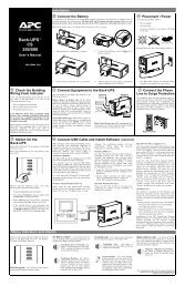
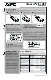
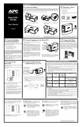
3. Install the Batteries<br />
The battery compartment is accessed from the front panel of the <strong>UPS</strong>. The <strong>5000</strong> VA unit requires four battery packs (each<br />
pack consists of four individual batteries).<br />
Note:<br />
Graphics are not drawn to scale. They are shown for reference only.<br />
4. Connect Power and Equipment to the <strong>UPS</strong><br />
1. Remove the front bezel by grasping the finger clips on the side of the<br />
bezel and carefully loosening the four (4) snaps.<br />
2. Use a screwdriver or coin to remove the two battery door screws and<br />
open the door.<br />
3. For rack mount units, hold a battery pack so its battery leads are on the<br />
right hand side and slide it into the <strong>UPS</strong>. For tower units, hold the battery<br />
such that the battery leads are on the top and slide it into the <strong>UPS</strong>. Push<br />
the battery pack to the back of the compartment.<br />
Note:<br />
Be careful lifting the batteries – they are heavy. Support the bottom of<br />
the batteries as you move them.<br />
4. Connect the battery leads to the <strong>UPS</strong> connector within the battery<br />
compartment.<br />
Note:<br />
Small sparks at the battery connectors are normal during connection.<br />
5. Tuck the white cord (that serves as a handle for the connector) neatly to<br />
the side.<br />
6. Repeat steps 3 through 5 to add the remaining battery packs.<br />
•= The <strong>UPS</strong> package includes six IEC jumper cords. Use these cords to connect your equipment to the <strong>UPS</strong>.<br />
•= Do not plug laser printers into the <strong>UPS</strong>.<br />
Caution:<br />
DO NOT use a standard serial interface cable to connect to the Computer Interface Port on the <strong>UPS</strong>. Standard<br />
serial interface cables are incompatible with the <strong>UPS</strong> connector. Use the cable provided with your <strong>UPS</strong>.<br />
•= Turn on all connected equipment.<br />
5. Connect Power to the <strong>UPS</strong><br />
•= Press the <strong>UPS</strong>’s ON switch to turn on your <strong>UPS</strong>. This will power-up connected equipment.<br />
•= The unit performs a self-test automatically when turned on, and every two weeks thereafter.<br />
•= The <strong>UPS</strong> charges its battery whenever it is connected to utility power. The battery charges fully during the first four<br />
hours of normal operation. Do not expect full runtime during this initial charge period.<br />
6. Install PowerChute and Accessories<br />
For additional computer system security, install PowerChute <strong>UPS</strong> monitoring software. It provides automatic unattended<br />
shutdown capabilities on most major network operating systems. Once PowerChute is loaded, install the PowerChute ®<br />
black communication cable between <strong>UPS</strong> and computer. See the Software Installation: Instruction Sheet for details.<br />
Notes:<br />
This <strong>UPS</strong> is equipped with two <strong>Smart</strong>Slots for accessories. See the <strong>APC</strong> website (www.apcc.com) for available<br />
accessories. If a standard accessory is installed in this <strong>UPS</strong>, a <strong>User</strong>’s <strong>Manual</strong> for the accessory is included.<br />
5<br />
990-7032A, Revision 3 7/01