APC Smart-UPS 5000 User Manual - ExcessUPS
APC Smart-UPS 5000 User Manual - ExcessUPS
APC Smart-UPS 5000 User Manual - ExcessUPS

You also want an ePaper? Increase the reach of your titles
YUMPU automatically turns print PDFs into web optimized ePapers that Google loves.
<strong>APC</strong> <strong>Smart</strong>-<strong>UPS</strong><br />
Uninterruptible Power Supply<br />
Model <strong>5000</strong>I<br />
<strong>User</strong>’s <strong>Manual</strong><br />
990-7032A, Revision 3 7/01
Entire contents copyright ©1999 by American Power Conversion. All rights reserved. Reproduction in whole or in part without<br />
permission is prohibited. <strong>Smart</strong>-<strong>UPS</strong> is a registered trademark of <strong>APC</strong>. All other trademarks are the property of their respective<br />
owners.<br />
990-7032A, Revision 3 7/01
<strong>Smart</strong> <strong>UPS</strong> Safety Guide English<br />
This Safety Guide contains important instructions that should be followed during installation and maintenance of the <strong>APC</strong> equipment and batteries.<br />
It is intended for <strong>APC</strong> customers who setup, install, relocate, or maintain <strong>APC</strong> equipment.<br />
Handling Safety<br />
•= Be careful. Do not lift heavy loads without assistance.<br />
= 120 lb.)<br />
•= Equipment with casters is built to move on a smooth surface without any obstacles.<br />
•= Do not use a ramp inclined at more than 10°.<br />
•= This equipment is intended for installation in a temperature-controlled indoor area (0 to 40ΓC (+32 to +104ΓF)), free of conductive contaminants.<br />
Electrical Safety<br />
•= Do not work alone under hazardous conditions.<br />
•= High short circuit current through conductive materials could cause severe burns.<br />
•= A licensed electrician is required to install permanently wired equipment.<br />
•= Check that the power cord(s), plug(s), and sockets are in good condition.<br />
•= To reduce the risk of electric shock when grounding cannot be verified, disconnect the equipment from the AC power outlet before installing or<br />
connecting to other equipment. Reconnect the power cord only after all connections are made.<br />
•= Do not handle any kind of metallic connector before the power has been removed.<br />
•= Use one hand, whenever possible, to connect or disconnect signal cables to avoid a possible shock from touching two surfaces with different<br />
electrical grounds.<br />
•= Connect the equipment to a three wire AC outlet (two poles plus ground). The receptacle must be connected to appropriate branch circuit/mains<br />
protection (fuse or circuit breaker). Connection to any other type of receptacle may result in a shock hazard.<br />
CAUTION! Deenergizing Safety<br />
•= If the equipment has an internal energy source (the battery), the output may be energized when the unit is not connected to an AC power outlet.<br />
•= To deenergize pluggable equipment: first press the Off button for more than one second to switch the equipment off. Next disconnect the<br />
equipment from the AC power outlet. Finally, disconnect the battery.<br />
•= To deenergize permanently wired equipment: set the power switch to standby . Next set the AC circuit breaker to standby . Then<br />
•=<br />
disconnect the batteries (including any expansion units). Finally, disconnect the AC power from the building power supply.<br />
Pluggable equipment includes a protective earth conductor which carries the leakage current from the load devices (computer equipment). Total<br />
leakage current must not exceed 3.5 mA.<br />
•= Use of this equipment in life support applications where failure of this equipment can reasonably be expected to cause the failure of the life<br />
support equipment or to significantly effect its safety or effectiveness is not recommended.<br />
WARNING! Battery Safety<br />
•= This equipment contains potentially hazardous voltages. Do not attempt to disassemble the unit. The only exception is for equipment<br />
containing batteries. Battery replacement using the procedures below is permissible. Except for the battery, the unit contains no user<br />
serviceable parts. Repairs are performed only by factory trained service personnel.<br />
Batteries must be recycled. Deliver the battery to an appropriate recycling facility or ship it to the supplier in the new<br />
battery’s packing material. See the new battery instructions for more information.<br />
•= Do not dispose of batteries in a fire. The batteries may explode.<br />
•= Do not open or mutilate batteries. They contain an electrolyte which is toxic and harmful to the skin and eyes.<br />
•= To avoid personal injury due to energy hazard, remove wrist watches and jewelry such as rings when replacing the batteries. Use tools with<br />
insulated handles.<br />
•= Replace batteries with the same number and type of batteries as originally installed in the equipment.<br />
Replacement and Recycling of Batteries<br />
See your dealer or the Battery Replacement Section of this <strong>User</strong>’s <strong>Manual</strong> for information on replacement battery kits and battery recycling.<br />
990-7032A, Revision 3 7/01
Table of Contents<br />
Introduction................................................................................................................................................................................................1<br />
Unpacking ..................................................................................................................................................................................................1<br />
Installation..................................................................................................................................................................................................2<br />
Initial Startup..............................................................................................................................................................................................6<br />
Operating Instructions ................................................................................................................................................................................8<br />
Storage........................................................................................................................................................................................................9<br />
Replacing the Battery ...............................................................................................................................................................................10<br />
<strong>User</strong> Configuration Items .........................................................................................................................................................................11<br />
How to Determine On-Battery Run Time.................................................................................................................................................11<br />
Specifications ...........................................................................................................................................................................................12<br />
Regulatory Agency Approvals..................................................................................................................................................................13<br />
Troubleshooting .......................................................................................................................................................................................14<br />
Service......................................................................................................................................................................................................15<br />
Limited Warranty .....................................................................................................................................................................................15<br />
<strong>APC</strong> Contact Information.........................................................................................................................................................................15<br />
Appendix A: Types of Racks and Mounting Hardware...........................................................................................................................16<br />
Racks........................................................................................................................................................................................................16<br />
Appendix B: Transporting Your <strong>Smart</strong>-<strong>UPS</strong>...........................................................................................................................................17<br />
i<br />
990-7032A, Revision 3 7/01
Introduction<br />
About Your New <strong>UPS</strong><br />
This Uninterruptible Power Supply (<strong>UPS</strong>) is designed to prevent blackouts, brownouts, sags and surges from reaching your computer<br />
and other valuable electronic equipment. This <strong>UPS</strong> also filters out small utility line fluctuations and isolates your equipment from large<br />
disturbances by internally disconnecting from the utility line, while supplying power from its internal batteries until the utility line<br />
returns to safe levels.<br />
While running on battery, an internal alarm will sound (periodic beeps). The on/test button may be pressed to silence the <strong>UPS</strong> alarm.<br />
If the utility power does not return, the <strong>UPS</strong> will continue supplying power to the connected equipment until exhausted. A continuous<br />
beeping will sound two minutes before the <strong>UPS</strong>’s final low battery shutdown. If using a computer, you must manually save your files<br />
and power down before the <strong>UPS</strong> turns itself off, unless you are using PowerChute ® interface software that provides automatic,<br />
unattended shutdown.<br />
Unpacking<br />
Inspection<br />
Inspect the <strong>UPS</strong> upon receipt. Notify the carrier and dealer if there is damage. The packaging is recyclable; save it for<br />
reuse or dispose of it properly.<br />
Contents<br />
The shipping package contains the <strong>UPS</strong>, its batteries (four battery packs), six IEC jumper cords, and, for rack mount units,<br />
rails to support the unit in a rack.<br />
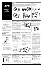
How to Unpack the <strong>UPS</strong><br />
Move the <strong>UPS</strong>, in its shipping package, as close to the desired location as possible. Then follow these instructions:<br />
Use scissors or a knife to cut<br />
the plastic straps and open the<br />
package.<br />
Unpack the box containing the<br />
mounting rails.<br />
Lift off the cardboard box that<br />
covers the top and sides of the<br />
package. The bottom of the<br />
box is formed by a wooden<br />
pallet.<br />
Lift the <strong>UPS</strong> up and out of the<br />
box.<br />
1<br />
Caution:<br />
Read this <strong>User</strong>’s <strong>Manual</strong> for safety<br />
information and installation<br />
instructions.<br />
Remove the foam spacers.<br />
The <strong>5000</strong> VA model requires two or more people to lift due to its weight.<br />
Pull the plastic bag down to expose the<br />
<strong>UPS</strong>.<br />
Remove the batteries from the pallet.<br />
990-7032A, Revision 3 7/01
Installation<br />
Installing your <strong>UPS</strong> requires six steps:<br />
1. Position the <strong>UPS</strong> in the desired location. For rack mount units this may include installing the rails into the rack.<br />
2. Hardwire the electrical connection on the input side (must be done by an authorized electrician).<br />
3. Install the batteries. This <strong>5000</strong> VA <strong>UPS</strong> ships without the batteries installed.<br />
4. Connect equipment to the <strong>UPS</strong>.<br />
5. Power up the <strong>UPS</strong>.<br />
6. Install PowerChute ® <strong>UPS</strong> monitoring software and accessories.<br />
1. Position the <strong>UPS</strong><br />
Placement<br />
990-7032A, Revision 3 7/01 2<br />
Install the <strong>UPS</strong> in a protected area that is free of excessive dust<br />
and has adequate air flow. Do not operate the <strong>UPS</strong> where the<br />
temperature and humidity are outside the specified limits.<br />
Warning!<br />
Changes or modifications to this unit not expressly approved by the party responsible for compliance<br />
could void the warranty.<br />
Installing Rack Mount Units<br />
The Rack Mount <strong>UPS</strong> comes with standard 19” (46.5 cm) rack mount brackets (ears) installed. It is supplied with L<br />
channel supports. These supports must be used with this model to ease installation for a 19” rack.<br />
Caution:<br />
Remove the <strong>UPS</strong> before moving the rack.<br />
Installing the <strong>UPS</strong> in a rack involves a four-step process:<br />
1. Determine the location of the <strong>UPS</strong> in the rack.<br />
2. Install the mounting rails in the rack.<br />
3. Load the <strong>UPS</strong> into the rack.<br />
4. Attach the mounting brackets to the rack.<br />
This section describes each step in detail.<br />
Determine the Location of the <strong>UPS</strong> in the Rack<br />
•= <strong>UPS</strong>s are heavy. Select a rack location sturdy enough to handle the weight. Mount the <strong>UPS</strong> at or near the bottom<br />
of the rack.<br />
•= Select a rack location with adequate air flow that is free from excessive dust. Ensure that any air vents on the<br />
sides of the <strong>UPS</strong> are not blocked. Do not operate the <strong>UPS</strong> where temperature or humidity are outside the limits<br />
listed under Specifications, page 12.
Determine the Location of the <strong>UPS</strong> in the Rack (continued)<br />
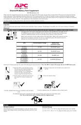
Install the Mounting Rails in the Rack<br />
1<br />
Remove the two screws that hold the rails together so<br />
that the rails can slide outward . Do not detach the rails.<br />
3<br />
<br />
<br />
Expand the rails so that it spans from the front rack post to<br />
the back rack post. Replace the two screws (removed in<br />
step 1) that hold the rail sections together.<br />
<br />
1. Determine where in the rack you’ll mount the <strong>UPS</strong>. The SU<strong>5000</strong><br />
requires a space of 5U. Some racks have tick marks to indicate<br />
the U-spaces.<br />
2. Using the mounting template provided (part number 990-0195),<br />
identify and mark the correct mounting holes for the <strong>UPS</strong><br />
mounting brackets.<br />
3. Locate and mark the bottom hole in the designated U-space .<br />
The bottom screw on the mounting rail will attach to the bottom<br />
hole in the U-space.<br />
4. Repeat steps 3 and 4 for the remaining three rack posts.<br />
5. Prepare the rack holes, if necessary. Racks with threaded holes<br />
require no preparation.<br />
3<br />
If your rack has round holes, insert clip nuts (provided) into<br />
the holes in step 2.<br />
If your rack has square holes, insert either clip or cage<br />
nuts into the holes marked in step 2 (cage nut shown).<br />
2<br />
Front<br />
Align the bottom hole on the mounting rail with the bottom<br />
hole in the U-space (marked in step 3 above). Use the flat,<br />
Phillips head screws (10-32) and conical washers to attach<br />
the front rail to the rack. Position the rails so that the lip of<br />
the rail is on the bottom.<br />
4<br />
Back<br />
Attach the rail to the back rack post using the same<br />
hardware (10-32 flat head screws and conical washers)<br />
used in step 2. Repeat the process for the other rails.<br />
Caution:<br />
990-7032A, Revision 3 7/01
The <strong>5000</strong> VA models (without batteries installed) require two people to lift due to their weight.<br />
2. Hardwire the Electrical Connection<br />
990-7032A, Revision 3 7/01 4<br />
Caution:<br />
Load the <strong>UPS</strong> into the Rack<br />
Supporting the <strong>UPS</strong> from the front and back,<br />
carefully align the unit with the rails. Slide the <strong>UPS</strong><br />
into position.<br />
Attach the Mounting Brackets to the Rack<br />
Use the ornamental screws supplied with the <strong>UPS</strong> to<br />
attach the mounting brackets to the rack post.<br />
The electrical connection must be made by an authorized electrician according to national and local regulations.<br />
Verify that the supply line contains a 25 Amp circuit breaker BEFORE hardwiring the <strong>UPS</strong>.<br />
Ensure that the batteries are not installed in the <strong>UPS</strong> until the hardwiring is complete.<br />
Incorporate a readily accessible disconnect device in the fixed wiring design.<br />
1. Select the appropriate wire size and connectors. For most applications, #10 AWG (5 sq. mm) wire should be<br />
sufficient.<br />
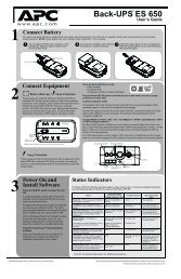
2. The input wiring terminal is located on the rear panel of the <strong>UPS</strong>. Remove the access door by unscrewing the single<br />
screw which holds it in place.<br />
Access Door Screw<br />
Wire Input Panel<br />
Access Door<br />
Screw<br />
Wire Input Panel<br />
3. Slide the wire input plate to the left on rack mount units and up on towers and remove it. This will expose the input<br />
wiring terminal.<br />
4. Use a screwdriver or any hard object to detach the circular knockout. You may need to use pliers to fully detach the<br />
knockout.<br />
5. Feed the wire cable through the hole in the wire input plate. Using a threaded lock nut, fasten the plate to the selected<br />
cable or conduit connector.<br />
6. Use a knife or pliers to strip off the plastic on the end of the cable to expose the copper wire. Strip all three wires.<br />
7. Use a flathead screwdriver to connect the wires to the terminal block inside the <strong>UPS</strong>. Loosen the screw, then feed the<br />
copper wire into the terminal block and tighten the screw. Connect the protective earth ground to the terminal block<br />
at the position marked with the ground symbol ( ). The <strong>UPS</strong> wiring color code is:<br />
GREEN for GROUND<br />
WHITE for NEUTRAL<br />
BLACK for HOT<br />
8. Once all the wires are connected to the terminal block, reconnect the wire input plate to the <strong>UPS</strong>. Align the plate,<br />
position it into the grooves, and slide it to the right.<br />
9. Inspect the connections and location of the excess wires before installing the access door.<br />
10. Replace the access door and fasten with the screw (removed in step 2).
3. Install the Batteries<br />
The battery compartment is accessed from the front panel of the <strong>UPS</strong>. The <strong>5000</strong> VA unit requires four battery packs (each<br />
pack consists of four individual batteries).<br />
Note:<br />
Graphics are not drawn to scale. They are shown for reference only.<br />
4. Connect Power and Equipment to the <strong>UPS</strong><br />
1. Remove the front bezel by grasping the finger clips on the side of the<br />
bezel and carefully loosening the four (4) snaps.<br />
2. Use a screwdriver or coin to remove the two battery door screws and<br />
open the door.<br />
3. For rack mount units, hold a battery pack so its battery leads are on the<br />
right hand side and slide it into the <strong>UPS</strong>. For tower units, hold the battery<br />
such that the battery leads are on the top and slide it into the <strong>UPS</strong>. Push<br />
the battery pack to the back of the compartment.<br />
Note:<br />
Be careful lifting the batteries – they are heavy. Support the bottom of<br />
the batteries as you move them.<br />
4. Connect the battery leads to the <strong>UPS</strong> connector within the battery<br />
compartment.<br />
Note:<br />
Small sparks at the battery connectors are normal during connection.<br />
5. Tuck the white cord (that serves as a handle for the connector) neatly to<br />
the side.<br />
6. Repeat steps 3 through 5 to add the remaining battery packs.<br />
•= The <strong>UPS</strong> package includes six IEC jumper cords. Use these cords to connect your equipment to the <strong>UPS</strong>.<br />
•= Do not plug laser printers into the <strong>UPS</strong>.<br />
Caution:<br />
DO NOT use a standard serial interface cable to connect to the Computer Interface Port on the <strong>UPS</strong>. Standard<br />
serial interface cables are incompatible with the <strong>UPS</strong> connector. Use the cable provided with your <strong>UPS</strong>.<br />
•= Turn on all connected equipment.<br />
5. Connect Power to the <strong>UPS</strong><br />
•= Press the <strong>UPS</strong>’s ON switch to turn on your <strong>UPS</strong>. This will power-up connected equipment.<br />
•= The unit performs a self-test automatically when turned on, and every two weeks thereafter.<br />
•= The <strong>UPS</strong> charges its battery whenever it is connected to utility power. The battery charges fully during the first four<br />
hours of normal operation. Do not expect full runtime during this initial charge period.<br />
6. Install PowerChute and Accessories<br />
For additional computer system security, install PowerChute <strong>UPS</strong> monitoring software. It provides automatic unattended<br />
shutdown capabilities on most major network operating systems. Once PowerChute is loaded, install the PowerChute ®<br />
black communication cable between <strong>UPS</strong> and computer. See the Software Installation: Instruction Sheet for details.<br />
Notes:<br />
This <strong>UPS</strong> is equipped with two <strong>Smart</strong>Slots for accessories. See the <strong>APC</strong> website (www.apcc.com) for available<br />
accessories. If a standard accessory is installed in this <strong>UPS</strong>, a <strong>User</strong>’s <strong>Manual</strong> for the accessory is included.<br />
5<br />
990-7032A, Revision 3 7/01
Initial Startup<br />
Rear Views<br />
<strong>5000</strong> VA Tower Model<br />
990-7032A, Revision 3 7/01 6<br />
<strong>5000</strong> VA Rack Mount Model<br />
Charge the battery<br />
The <strong>UPS</strong> charges its battery whenever it is connected to utility power. The battery will charge fully during the first four<br />
hours of normal operation. Do not expect full runtime during this initial charge period.<br />
Connect Computer Interface Port (Optional)<br />
Power management software and interface kits can be used with this <strong>UPS</strong>. Use only kits supplied or approved by the<br />
manufacturer. If used, connect the interface cable to the 9-pin computer interface port on the back panel of the <strong>UPS</strong>.<br />
Secure the connector’s screws to complete the connection.<br />
Caution:<br />
DO NOT use a standard serial interface cable to connect to the Computer Interface Port on the <strong>UPS</strong>. Standard<br />
serial interface cables are incompatible with the <strong>UPS</strong> connector. Use the cable provided with your <strong>UPS</strong>.<br />
Connect Ground Leads to TVSS Connector (Optional)<br />
The <strong>UPS</strong> features a TVSS connector for connecting the ground lead on transient voltage surge-suppression (TVSS)<br />
devices such as telephone and network line protectors. The TVSS connector provides grounding through the <strong>UPS</strong>’s power<br />
cord ground conductor. To make a connection to the TVSS connector, loosen the screw and connect the surge<br />
suppression device’s ground lead. Tighten the screw to secure the lead.<br />
Voltage Sensitivity<br />
The <strong>UPS</strong> detects line voltage distortions such as spikes, notches, dips, and swells, as well as distortions caused by<br />
operation with inexpensive fuel-powered generators. By default, the <strong>UPS</strong> reacts to distortions by transferring to on-battery<br />
operation to protect the loads. Where power quality is poor, the <strong>UPS</strong> may frequently transfer to on-battery operation. If<br />
the loads can operate normally under such conditions, battery capacity and service life may be conserved by reducing the<br />
sensitivity of the <strong>UPS</strong>.<br />
To reduce <strong>UPS</strong> sensitivity, press the configuration button on the rear panel. Use a pointed object such as a pen to<br />
press the button. Press it once to set the <strong>UPS</strong>’s sensitivity to reduced. Press it again to set the sensitivity to low. Press<br />
the button a third time to reset normal sensitivity.<br />
normal<br />
reduced<br />
low<br />
When the <strong>UPS</strong> is set to normal sensitivity, the configuration LED is brightly lit.<br />
When it is set to reduced sensitivity, the LED is dimly lit.<br />
When it is set to low sensitivity, the LED is off.
Low Battery Warning Interval<br />
By default, the low battery warning occurs when there are approximately two minutes of on-battery run time remaining.<br />
This may not be enough time to gracefully shut down some protected computer systems.<br />
To change the warning interval, press the rear panel configuration button while pressing and holding the front-panel<br />
on/test button.<br />
2 min.<br />
5 min.<br />
7 min.<br />
The initial setting.<br />
Press the configuration button once to set the low battery warning interval to approximately five minutes.<br />
Press it again to set the interval to approximately seven minutes.<br />
Press the button a third time to reset the interval to two minutes.<br />
7<br />
990-7032A, Revision 3 7/01
Operating Instructions<br />
Switch On — Switch Off<br />
With the <strong>UPS</strong> plugged in, press and release the large upper on/test button to supply power to the loads. The loads are<br />
immediately powered while the <strong>UPS</strong> beeps and performs a self-test.<br />
Press and release the small, lower off button to turn off power to the loads. It may be convenient to use the <strong>UPS</strong> as a<br />
master on/off switch for the protected equipment.<br />
Note: Whenever the <strong>UPS</strong> is plugged in and utility voltage is present, the charger maintains battery charge.<br />
The on-line LED illuminates when the <strong>UPS</strong> is supplying utility power to the loads.<br />
On Battery<br />
During on-battery operation, the on-battery LED illuminates and the <strong>UPS</strong> sounds an audible alarm consisting of four beeps<br />
every 30 seconds. The alarm stops when the <strong>UPS</strong> returns to on-line operation.<br />
Battery Charge Bar Graph<br />
100%<br />
80%<br />
60%<br />
40%<br />
20%<br />
The 5-LED display on the right of the front panel shows the present charge of the <strong>UPS</strong>’s battery as a<br />
percentage of the battery’s capacity. When all five LEDs light, the battery is fully charged. The top LED goes<br />
out whenever the battery is not 100% charged. When the lowest LED is flashing, the battery can supply less<br />
than two minutes of run time for the load.<br />
Shutdown Mode<br />
In shutdown mode the <strong>UPS</strong> stops supplying power to the load, waiting for the return of utility power. If there is no<br />
utility power present, external devices (e.g., servers) connected to the computer interface or the accessory slot can<br />
command the <strong>UPS</strong> to shut down. This is normally done to preserve battery capacity after the graceful shutdown of<br />
protected servers. The <strong>UPS</strong> will scroll the front panel indicators sequentially in shutdown mode.<br />
Self-test<br />
The <strong>UPS</strong> performs a self-test automatically when turned on, and every two weeks thereafter (by default). Automatic selftest<br />
eases maintenance requirements by eliminating the need for periodic manual self-tests.<br />
During the self-test, the <strong>UPS</strong> briefly operates the loads on-battery. If the <strong>UPS</strong> passes the self-test, it returns to on-line<br />
operation.<br />
If the <strong>UPS</strong> fails the self-test it immediately returns to on-line operation and lights the replace battery LED.<br />
The loads are not affected by a failed test. Recharge the battery overnight and perform the self-test again. If the<br />
replace battery LED is still on, replace the battery using the procedure in Replacing the Battery, page 10.<br />
Replace Battery<br />
If the battery fails a self-test, the <strong>UPS</strong> emits short beeps for one minute and the replace battery LED illuminates. The <strong>UPS</strong><br />
repeats the alarm every five hours. Perform the self-test procedure to confirm replace battery conditions. The alarm stops<br />
when the battery passes the self-test.<br />
990-7032A, Revision 3 7/01 8
Load Bar Graph<br />
85%<br />
67%<br />
50%<br />
33%<br />
17%<br />
The 5-LED display on the left of the front panel represents the power drawn from the <strong>UPS</strong> as a percentage of<br />
total capacity. For example, if three LEDs are lit, the load is drawing between 50% and 67% of the <strong>UPS</strong>’s<br />
capacity. If all five LEDs light, thoroughly test your complete system to make sure that the <strong>UPS</strong> will not become<br />
overloaded.<br />
Overload<br />
When the <strong>UPS</strong> is overloaded (when the connected loads exceed the maximum specified in the “maximum load” section<br />
under Specifications, page 12), the overload LED comes on and the <strong>UPS</strong> emits a sustained tone. The alarm remains on<br />
until the overload is removed. Disconnect nonessential load equipment from the <strong>UPS</strong> to eliminate the overload.<br />
<strong>Smart</strong>Trim<br />
The <strong>Smart</strong>Trim LED comes on to indicate that the <strong>UPS</strong> is compensating for a high voltage.<br />
<strong>Smart</strong>Boost<br />
The <strong>Smart</strong>Boost LED comes on to indicate that the <strong>UPS</strong> is compensating for a low voltage.<br />
Low Battery<br />
When the <strong>UPS</strong> is operating on-battery and the energy reserve of the battery runs low, the <strong>UPS</strong> beeps continuously until the<br />
<strong>UPS</strong> shuts down from battery exhaustion or returns to on-line operation.<br />
Cold Start<br />
When the <strong>UPS</strong> is off and there is no utility power, use the cold start feature to apply power to the loads from the <strong>UPS</strong>’s<br />
battery.<br />
•= Press and hold the on/test button until the <strong>UPS</strong> beeps.<br />
Note:<br />
Cold start is not a normal condition.<br />
•=Release the on/test button during the beep and the loads are powered within four seconds.<br />
Note:<br />
The <strong>UPS</strong> starts a self-test as a part of this procedure. The self-test does not affect the voltage display. The utility<br />
voltage bar graph has a margin of error of ± 4%.<br />
Storage<br />
Storage Conditions<br />
Store the <strong>UPS</strong> covered and upright in a cool, dry location, with its battery fully charged. Before storing, charge the <strong>UPS</strong><br />
for at least two hours. Remove any accessories in the accessory slot and disconnect any cables connected to the computer<br />
interface port to avoid unnecessarily draining the battery.<br />
Extended storage<br />
At -15 to +30 °C (+5 to +86 °F), charge the <strong>UPS</strong>’s battery every six months.<br />
At +30 to +45 °C (+86 to +113 °F), charge the <strong>UPS</strong>’s battery every three months.<br />
9<br />
990-7032A, Revision 3 7/01
Replacing the Battery<br />
This <strong>UPS</strong> has an easy to replace hot-swappable battery. The battery compartment is located on the front panel for easy<br />
access. Battery replacement is a safe procedure, isolated from electrical hazards. You may leave the <strong>UPS</strong> and loads on<br />
for the following procedure. See your dealer or call the number in this manual for information on replacement battery<br />
cartridges.<br />
Note:<br />
Please read the cautions in <strong>Smart</strong> <strong>UPS</strong> Safety Guide, at the front of this manual. Once the battery is disconnected,<br />
the loads are not protected from power outages.<br />
990-7032A, Revision 3 7/01 10<br />
Model # Replacement Battery Cartridge (RBC) #<br />
SU<strong>5000</strong>I RBC 12<br />
SU<strong>5000</strong>RMI5U RBC 12<br />
Note:<br />
Graphics are not drawn to scale. They are shown for reference only.<br />
1. Remove the front bezel by grasping the finger clips on the side of the bezel and carefully<br />
loosening the four (4) snaps.<br />
2. Use a screwdriver or coin to remove the two battery door screws and open the door.<br />
3. Disconnect the front battery pack. Grip the white cord on the first front set of batteries and<br />
pull firmly to disconnect the connector from the battery compartment.<br />
4. Pull the front battery out of the <strong>UPS</strong> by pulling the clear label, not the white cord. The white<br />
cord is connected to the battery leads, not the body of the battery.<br />
5. Disconnect and remove the remaining battery packs by repeating steps 2 and 3.<br />
Notes:<br />
Be careful removing the batteries - they are heavy. Support the bottom of the batteries as<br />
you remove them.<br />
The <strong>5000</strong> VA model has two stacked sets of batteries. Exercise special care when removing<br />
the top set.<br />
6. Replace the back battery pack. For rack mount units, hold a battery pack so its battery leads<br />
are on the right-hand side and slide it into the <strong>UPS</strong>. For tower units, hold the battery such that<br />
the battery leads are on the top and slide it into the <strong>UPS</strong>. Push the battery pack to the back of<br />
the compartment.<br />
7. Reconnect the battery pack by pressing the gray connector into the plug at the right-hand side<br />
(rack mount units) or top (tower units) of the battery housing.<br />
Note:<br />
Small sparks at the battery connectors are normal during connection.<br />
8. Repeat steps 6 and 7 for the remaining battery packs.<br />
9. Close the battery door, replace the screws, and replace the front cover.<br />
Batteries must be recycled. Deliver the battery to an appropriate recycling facility or ship it to<br />
the supplier in the new battery’s packing material. See the instructions included with the new<br />
battery for more information.
<strong>User</strong> Configuration Items<br />
Note: Setting these items requires optional software or hardware.<br />
Function Factory Default <strong>User</strong> Selectable Choices Description<br />
Automatic Self-Test Every 14 days Every 7 days (168 hours), On Sets the interval at which the <strong>UPS</strong> will execute a self-test.<br />
(336 hours) Startup Only, No Self-Test<br />
<strong>UPS</strong> ID <strong>UPS</strong>_IDEN Up to eight characters to define<br />
the <strong>UPS</strong>.<br />
11<br />
Use this field to uniquely identify the <strong>UPS</strong> for network<br />
management purposes.<br />
Date of Last Battery Replacement Manufacture Date Date of Battery Replacement Reset this date on battery replacement.<br />
Minimum Capacity Before Return from<br />
Shutdown<br />
0 percent 15, 50, 90 percent The <strong>UPS</strong> will charge its batteries to the specified percentage<br />
before return from a shutdown.<br />
Sensitivity Normal Reduced, Low Set lower than normal sensitivity to avoid lowered battery<br />
capacity and service life in situations where the load can<br />
tolerate minor power disturbances.<br />
Duration of Low Battery Warning 2 minutes 5, 7, 10 minutes Sets the time before shutdown at which the <strong>UPS</strong> issues a low<br />
battery warning. Set higher than the default only if the OS<br />
needs the time for graceful shutdown.<br />
Alarm Delay After Line Fail 5 second delay 30 second delay, At Low Battery<br />
Condition, No Alarm<br />
To avoid alarms for minor power glitches, set the alarm delay.<br />
Shutdown Delay 20 seconds 180, 300, 600 seconds Sets the interval between when the <strong>UPS</strong> receives a shutdown<br />
command and when shutdown occurs.<br />
Synchronized Turn-on Delay 0 seconds 60, 180, 300 seconds To avoid branch circuit overload, the <strong>UPS</strong> will wait the<br />
specified time after the return of utility power before turn-on.<br />
High Transfer Point 253 264, 271, 280 To avoid unnecessary battery usage, set the High Transfer<br />
Point higher if the utility voltage is chronically high and the<br />
load is known to work well under this condition.<br />
Low Transfer Point 196 188, 204, 208 Set the Low Transfer Point lower if the utility voltage is<br />
chronically low and the load can tolerate this condition.<br />
How to Determine On-Battery Run Time<br />
Tower and 5U Rack Mount <strong>5000</strong> VA Models<br />
Note:<br />
<strong>UPS</strong> battery life differs based on usage and environment.<br />
Typical On-Battery Run Time Versus Load, in Hours<br />
Load <strong>5000</strong> VA Internal Battery<br />
100 VA 7.17<br />
150 VA 5.95<br />
200 VA 5.04<br />
300 VA 3.88<br />
400 VA 2.96<br />
500 VA 2.37<br />
600 VA 1.92<br />
800 VA 1.40<br />
1000 VA 1.06<br />
1200 VA 0.83<br />
1400 VA 0.65<br />
1600 VA 0.54<br />
2000 VA 0.39<br />
2200 VA 0.33<br />
2500 VA 0.26<br />
3000 VA 0.19<br />
3500 VA 0.16<br />
4000 VA 0.13<br />
4500 VA 0.11<br />
<strong>5000</strong> VA 0.09<br />
990-7032A, Revision 3 7/01
Specifications<br />
Acceptable input voltage 0 - 325 VAC<br />
Output voltage 196 - 253 VAC<br />
Input protection Resettable circuit breaker<br />
Frequency limits (on-line operation) 47 - 63 Hz<br />
Transfer time 2 ms typical, 4 ms maximum<br />
Maximum load, total <strong>5000</strong> VA/3750 W<br />
On-battery output voltage 220, 225, 230, or 240 VAC<br />
On-battery frequency 50 or 60 Hz, 0.1 Hz;<br />
unless synchronized to utility during brownout<br />
On-battery waveshape Low-distortion sine wave<br />
Overload protection (on-battery) Overcurrent and short-circuit protected, latching shutdown on overload<br />
Noise filter Normal and common mode EMI/RFI suppression,<br />
100 kHz to 10 MHz<br />
Battery type Spill proof, maintenance free, sealed lead-acid<br />
Typical battery life 3 to 6 years, depending on number of discharge cycles<br />
and ambient temperature<br />
Typical recharge time 2 to 5 hours from total discharge<br />
Operating temperature 0 to 40ΓC (+32 to +104ΓF)<br />
Storage temperature -15 to +45ΓC (+5 to +113ΓF)<br />
Operating and storage relative humidity 0 to 95%, non-condensing<br />
Operating elevation 0 to +3,000 m (0 to +10,000 ft.)<br />
Storage elevation 0 to +15,000 m (0 to +50,000 ft.)<br />
Electromagnetic Compatibility (EMC) EN50091-2<br />
Electromagnetic Interference (EMI) EN55022 Class A<br />
Electromagnetic Immunity IEC 801-2, 801-3, 801-4, 801-5, 1000-2-2<br />
EN60555-1, -2, -3, EN61000-4-1, EN61000-4-11<br />
Audible noise in dBA at 1 m (3 ft.) z55<br />
Safety approvals GS licensed by VDE to EN50091-1-1 and 60950<br />
Rack Mount Units RM Unit<br />
Size (W x H x D) 43.2 x 19.6 x 62.2 cm<br />
(17.0 x 8.7 x 24.5 in.)<br />
Weight - net (shipping) 205 (235) lb.<br />
93 (106.6) kg<br />
Tower Units Tower Unit<br />
Size (W x H x D) 19.6 x 43.2 x 62.2 cm<br />
(8.7 x 17.5 x 26.0 in.)<br />
Weight - net (shipping) 200 (240) lb.<br />
93 (106.6) kg<br />
990-7032A, Revision 3 7/01 12
Regulatory Agency Approvals<br />
N 394<br />
13<br />
B ME<br />
61<br />
990-7032A, Revision 3 7/01
Troubleshooting<br />
Use the chart below to solve minor <strong>UPS</strong> installation problems. Contact <strong>APC</strong> Technical Support Staff for assistance with<br />
complex <strong>UPS</strong> problems. See <strong>APC</strong> Contact Information, page 15, for a location near you.<br />
Problem and Possible Cause Solution<br />
<strong>UPS</strong> will not turn on.<br />
•=ON button not pushed. Press the ON button once to power the <strong>UPS</strong> and the load.<br />
•=<strong>UPS</strong> not connected to AC power supply. Check that the power cable from the <strong>UPS</strong> to the power<br />
supply is securely connected at both ends.<br />
•=<strong>UPS</strong> input circuit breaker tripped. Reduce the load on the <strong>UPS</strong> by unplugging equipment and<br />
reset the circuit breaker (on back of <strong>UPS</strong>) by pressing the<br />
plunger back in.<br />
•=Very low or no utility voltage. Check the AC power supply to the <strong>UPS</strong> with a table lamp.<br />
If very dim, have the utility voltage checked.<br />
•=Battery not connected properly. Confirm the battery connections.<br />
<strong>UPS</strong> will not turn off.<br />
•=Internal <strong>UPS</strong> fault. Do not attempt to use the <strong>UPS</strong>. Unplug the <strong>UPS</strong> and have it<br />
serviced immediately.<br />
<strong>UPS</strong> operates on-battery although normal line voltage exists.<br />
•=<strong>UPS</strong>’s input circuit breaker tripped. Reduce the load on the <strong>UPS</strong> by unplugging equipment and<br />
reset the circuit breaker (on back of <strong>UPS</strong>) by pressing the<br />
•=Very high, low, or distorted line voltage.<br />
Inexpensive fuel powered generators can distort<br />
the voltage.<br />
990-7032A, Revision 3 7/01 14<br />
plunger back in.<br />
Move the <strong>UPS</strong> to a different outlet on a different circuit.<br />
Test the input voltage with the utility voltage display. If<br />
acceptable to the load, reduce the <strong>UPS</strong>’s sensitivity. Refer<br />
to Voltage Sensitivity, page 6, for procedures.<br />
<strong>UPS</strong> beeps occasionally.<br />
•=Normal <strong>UPS</strong> operation. None. The <strong>UPS</strong> is protecting the load.<br />
<strong>UPS</strong> does not provide expected backup time.<br />
•=The <strong>UPS</strong>’s battery is weak due to recent outage or<br />
is near the end of its service life.<br />
Charge the battery. Batteries require recharging after<br />
extended outages. Also, they wear faster when put into<br />
service often or when operated at elevated temperatures.<br />
If the battery is near the end of its service life, consider<br />
replacing the battery even if the replace battery indicator is<br />
not yet lit.<br />
•=The <strong>UPS</strong> is overloaded. Check the <strong>UPS</strong>’s load display. Unplug less needed<br />
equipment, such as printers.<br />
Front panel indicators flash sequentially.<br />
•=The <strong>UPS</strong> has been shut down by remote control. None. The <strong>UPS</strong> will restart automatically when utility<br />
power returns.<br />
All indicators are lit and <strong>UPS</strong> emits a constant beeping.<br />
•=Internal <strong>UPS</strong> fault. Do not attempt to use the <strong>UPS</strong>. Turn the <strong>UPS</strong> off and have<br />
it serviced immediately.<br />
All indicators are off and <strong>UPS</strong> is plugged into wall outlet.<br />
•=The <strong>UPS</strong> is shut down and the battery is<br />
None. The <strong>UPS</strong> will return to normal operation when the<br />
discharged from an extended outage.<br />
The replace battery light is lit.<br />
power is restored and the battery has a sufficient charge.<br />
•=Weak batteries. Do another self test to see if it clears.<br />
•=Replacement batteries not connected properly. Confirm the battery connections.
Service<br />
If the <strong>UPS</strong> requires service do not return it to the dealer!<br />
Follow these steps:<br />
1. Review the problems discussed in Troubleshooting, page 14, to eliminate common problems.<br />
2. Verify that no circuit breakers are tripped. A tripped circuit breaker is the most common <strong>UPS</strong> problem!<br />
3. If the problem persists, call Customer Service or visit the <strong>APC</strong> Internet Website (www.apcc.com).<br />
•=Note the model number of the <strong>UPS</strong>, the serial number, and the date purchased. A technician will ask you to<br />
describe the problem and try to solve it over the phone, if possible. If this is not possible the technician will<br />
issue a Returned Material Authorization Number (RMA#).<br />
•=If the <strong>UPS</strong> is under warranty, repairs are free. If not, there is a repair charge.<br />
4. Pack the <strong>UPS</strong> in its original packaging. If the original packing is not available, ask Customer Service about obtaining<br />
a new set.<br />
Note:<br />
Pack the <strong>UPS</strong> properly to avoid damage in transit. Never use Styrofoam beads for packaging. Damage sustained<br />
in transit is not covered under warranty.<br />
5. Mark the RMA# on the outside of the package.<br />
6. Return the <strong>UPS</strong> by insured, prepaid carrier to the address given to you by Customer Service.<br />
Limited Warranty<br />
American Power Conversion (<strong>APC</strong>) warrants its products to be free from defects in materials and workmanship for a period of two years from the date<br />
of purchase. Its obligation under this warranty is limited to repairing or replacing, at its own sole option, any such defective products. To obtain<br />
service under warranty you must obtain a Returned Material Authorization (RMA) number from customer support (see the Service section of the <strong>User</strong>’s<br />
<strong>Manual</strong>). Products must be returned with transportation charges prepaid and must be accompanied by a brief description of the problem encountered<br />
and proof of date and place of purchase. This warranty does not apply to equipment which has been damaged by accident, negligence, or<br />
misapplication or has been altered or modified in any way. This warranty applies only to the original purchaser who must have properly registered the<br />
product within 10 days of purchase.<br />
EXCEPT AS PROVIDED HEREIN, AMERICAN POWER CONVERSION MAKES NO WARRANTIES, EXPRESSED OR IMPLIED, INCLUDING<br />
WARRANTIES OF MERCHANTABILITY AND FITNESS FOR A PARTICULAR PURPOSE. Some states do not permit limitation or exclusion of<br />
implied warranties; therefore, the aforesaid limitation(s) or exclusion(s) may not apply to the purchaser.<br />
EXCEPT AS PROVIDED ABOVE, IN NO EVENT WILL <strong>APC</strong> BE LIABLE FOR DIRECT, INDIRECT, SPECIAL, INCIDENTAL, OR<br />
CONSEQUENTIAL DAMAGES ARISING OUT OF THE USE OF THIS PRODUCT, EVEN IF ADVISED OF THE POSSIBILITY OF SUCH<br />
DAMAGE. Specifically, <strong>APC</strong> is not liable for any costs, such as lost profits or revenue, loss of equipment, loss of use of equipment, loss of software,<br />
loss of data, costs of substitutes, claims by third parties, or otherwise.<br />
<strong>APC</strong> Contact Information<br />
Internet www.apc.com/support/contact<br />
15<br />
990-7032A, Revision 3 7/01
Appendix A: Types of Racks and Mounting Hardware<br />
This appendix describes the hardware required for the different types of racks and describes the type of racks that may be<br />
used in your industry. All <strong>APC</strong> Rack Mount units are shipped ready for 19-inch wide EIA/IEC rack cabinets. Refer to the<br />
instructions included with the rails when mounting the <strong>UPS</strong>.<br />
Racks<br />
There are different types of racks:<br />
•=Equipment Rack - usually an open rack with threaded mounting holes or no threaded holes<br />
•=<strong>APC</strong> Netshelter, IBM (Vero, others) - enclosed rack with square holes<br />
•=Dell, Compaq (Rittal) - enclosed rack with square holes<br />
•=HP Rack - enclosed rack with round holes<br />
These racks differ in the methods required for mounting equipment. They may have threaded<br />
holes (hardware not included), round holes (require clip nut, shown below), or square holes<br />
(require cage nut, shown below).<br />
•=Telecomm Rack - open rack with two poles/four poles and threaded round holes (hardware not<br />
supplied by <strong>APC</strong>).<br />
Notes:<br />
Remove batteries to reduce <strong>UPS</strong> weight.<br />
For larger, heavier units, installation should be performed by two people.<br />
Check the type of rack you have against the hardware required for mounting in the table below.<br />
Rack Type Hole Type Hardware Required Hardware Included<br />
Equipment Rack Threaded or<br />
No Threads<br />
990-7032A, Revision 3 7/01 16<br />
See rack specifications if threaded.<br />
If not threaded use <strong>APC</strong> hardware.<br />
N/A if threaded.<br />
If not threaded use <strong>APC</strong><br />
hardware.<br />
Netshelter/Compaq/IBM/Dell Square Cage nut, 10-32 screws 810-2008, 810-0002<br />
HP Round Clip nut, 10-32 screws 810-2004, 810-0002<br />
Telecomm Threaded See rack specifications N/A
Appendix B: Transporting Your <strong>Smart</strong>-<strong>UPS</strong><br />
Follow these guidelines if you need to ship the <strong>UPS</strong> to another location. These guidelines apply whether you are<br />
transporting the <strong>UPS</strong> alone, rack mounted in an equipment cabinet, or installed in a system.<br />
Caution:<br />
Always DISCONNECT THE BATTERIES before shipping the <strong>UPS</strong> to avoid damage during transport.<br />
(U.S. Federal Regulation requires that batteries be disconnected during shipment.) The batteries may<br />
remain in the <strong>UPS</strong>; they do not have to be removed.<br />
This requirement applies whether the <strong>UPS</strong> is shipped alone or installed in an equipment rack<br />
or system.<br />
17<br />
Note:<br />
Graphics are not drawn to scale. They are shown for reference only.<br />
The battery compartment is accessed from the front panel of the <strong>UPS</strong>. The SU<strong>5000</strong> unit has four battery packs (each with<br />
four individual batteries).<br />
1. Remove the front bezel by grasping the finger clips on the side<br />
of the bezel and carefully loosening the four (4) snaps.<br />
2. Use a screwdriver or coin to remove the two battery door screws<br />
and open the door.<br />
3. Disconnect the front battery pack. Grasp the white cord on the<br />
first front set of batteries and pull firmly to disconnect the<br />
connector from the battery compartment.<br />
4. Tuck the white cord (that serves as a handle for the connector)<br />
neatly to the side.<br />
5. Disconnect the remaining battery packs by repeating steps 3 and<br />
4.<br />
6. Once all the batteries have been disconnected, close the battery<br />
door and replace the two (2) screws removed in step 2.<br />
7. Align the front bezel with the opening on the front of the <strong>UPS</strong><br />
and snap it into place.<br />
Note:<br />
Remember to connect the batteries once the SU<strong>5000</strong> has arrived at its destination.<br />
990-7032A, Revision 3 7/01