Back-UPS™ 350/500 CS - ExcessUPS
Back-UPS™ 350/500 CS - ExcessUPS
Back-UPS™ 350/500 CS - ExcessUPS

You also want an ePaper? Increase the reach of your titles
YUMPU automatically turns print PDFs into web optimized ePapers that Google loves.
w w w.apc.com<br />
<strong>Back</strong>-UPS <br />
<strong>CS</strong><br />
<strong>350</strong>/<strong>500</strong><br />
User’s Manual<br />
990-2084A 2/02<br />
3 Check the Building<br />
Wiring Fault Indicator<br />
If the red Building Wiring Fault indicator on the<br />
rear panel of the <strong>Back</strong>-UPS is lit, one of the<br />
following conditions exists:<br />
• Open or high resistance ground<br />
• Hot or neutral polarity reversed<br />
• Overloaded neutral circuit<br />
A lit indicator means that a potential shock<br />
hazard exists. Improper building wiring should<br />
be corrected by a qualified electrician. Do not<br />
use the <strong>Back</strong>-UPS until the condition that caused<br />
the fault is corrected.<br />
Note: Improper building wiring will not prevent the<br />
<strong>Back</strong>-UPS from operating, but it will limit its<br />
protection capability. It may also result in<br />
equipment damage that is not covered by the APC<br />
Equipment Protection Policy.<br />
6 Switch On the<br />
<strong>Back</strong>-UPS<br />
Note: Allow the <strong>Back</strong>-UPS to charge for a full eight<br />
hours prior to use.<br />
Press the push-button on the front panel of the<br />
<strong>Back</strong>-UPS.<br />
On Line<br />
On Battery<br />
Overload<br />
Replace Battery<br />
Observe that the following events occur after<br />
pressing and releasing the push-button:<br />
• The green On-Line indicator flashes.<br />
• The yellow On Battery indicator lights while<br />
the Self-Test is being performed.<br />
• When Self-Test has successfully completed,<br />
only the green On Line indicator will be lit.<br />
• If the internal battery is not connected, (see<br />
Step 1 above) the green On Line indicator and<br />
red Replace Battery indicator will light. The<br />
<strong>Back</strong>-UPS will also emit a chirping sound.<br />
There are four status indicators (lights) on the front<br />
panel of the <strong>Back</strong>-UPS (On Line, On Battery,<br />
Overload, and Replace Battery).<br />
On Line<br />
On Battery<br />
Overload<br />
Replace Battery<br />
®<br />
Status Indicators and Alarms<br />
On Line (green) - is lit whenever utility power<br />
is powering the Battery <strong>Back</strong>up outlets.<br />
Installation<br />
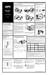
1 Connect the Battery<br />
In compliance with Department of Transportation (DOT) regulations, the <strong>Back</strong>-UPS is shipped with the<br />
internal red battery wire disconnected. The <strong>Back</strong>-UPS will not operate until the internal red wire is connected<br />
to the battery. Once connected, allow the <strong>Back</strong>-UPS to charge for a full eight hours prior to use.<br />
Note: Small sparks may occur during battery connection. This is normal.<br />
a. Open the battery compartment, as shown. c. Connect the red battery wire to the positive<br />
battery terminal.<br />
b. Pull the battery about half way out, as shown<br />
d. Push the battery into the battery compartment<br />
and re-install the cover, as shown.<br />
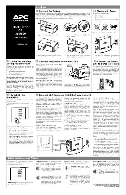
4 Connect Equipment to the <strong>Back</strong>-UPS<br />
The rear panel of the <strong>Back</strong>-UPS consists of the<br />
following elements:<br />
Battery <strong>Back</strong> Up Outlets (qty. of 3). These<br />
outlets provide battery back-up, surge protection,<br />
and Electro-magnetic Interference (EMI) filtering.<br />
In case of power outage, battery power is<br />
automatically provided to these outlets. Power<br />
(utility or battery) is not supplied to these outlets<br />
when the <strong>Back</strong>-UPS is switched Off. Connect a<br />
computer, monitor, and external disk or CD-ROM<br />
drive to these outlets.<br />
Surge Only Outlets (qty. of 3). These outlets are<br />
always On (when utility power is available) and<br />
are not controlled by the On/Off switch. These<br />
outlets do not provide power during a power<br />
outage. Connect a printer, fax machine or scanner<br />
to these outlets.<br />
Computer<br />
External<br />
Drive<br />
Monitor<br />
Fax<br />
Printer<br />
Scanner<br />
Black Velcro Straps (qty. of 2 - not shown). For<br />
convenience, two velcro traps have been included<br />
and can be used to manage power cords.<br />
7 Connect USB Cable and Install Software (optional)<br />
Note: The <strong>Back</strong>-UPS software CD-ROM provides<br />
data reporting and unattended shutdown of<br />
computers connected to the device. The User’s<br />
Guide contains additional information about the<br />
<strong>Back</strong>-UPS software. The User’s Guide is<br />
contained in the main folder with the CD-ROM.<br />
Attention: USB Hubs<br />
The <strong>Back</strong>-UPS should be plugged into the USB<br />
port of the computer, not into a USB hub.<br />
The computer must be powered On before<br />
connecting the USB cable. Connect the USB cable<br />
end (USB symbol facing down) to the rear panel<br />
USB port of the <strong>Back</strong>-UPS. Connect the other end<br />
of the USB cable to the USB port (usually located<br />
on the rear panel of the computer).<br />
For other Microsoft ® Windows ® or Macintosh ®<br />
operating systems, please follow the steps below,<br />
as appropriate:<br />
Windows 98 and Windows Me Users<br />
Please insert the APC PowerChute ® Personal<br />
Edition Software CD-ROM included with your<br />
<strong>Back</strong>-UPS into the CD-ROM drive of your<br />
RJ-45 to USB<br />
CABLE<br />
On Battery (yellow) - is lit whenever the battery<br />
of the <strong>Back</strong>-UPS is powering equipment connected<br />
to the Battery <strong>Back</strong>up Outlets.<br />
Four Beeps Every 30 Seconds - this<br />
alarm is sounded whenever the <strong>Back</strong>-<br />
UPS is running On Battery. Consider<br />
saving work in progress.<br />
Continuous Beeping - this alarm is<br />
sounded whenever a low battery condition<br />
is reached. Battery run-time is<br />
very low. Promptly save any work in<br />
progress and exit all open applications.<br />
Shutdown the operating system,<br />
computer and the <strong>Back</strong>-UPS.<br />
TO COMPUTER<br />
USB PORT<br />
computer. The installation program will load<br />
automatically. Please follow the on-screen<br />
instructions to install the software.<br />
Windows 2000 Users<br />
The APC PowerChute Personal Edition Software<br />
CD-ROM included with your UPS contains a<br />
“wizard” that optimizes your system’s power<br />
settings for operation with your <strong>Back</strong>-UPS. It does<br />
this by changing various settings in Power<br />
Options Properties in the Control Panel. APC<br />
strongly advises you to reconfigure your system<br />
by running this wizard.<br />
1. Insert the APC PowerChute Personal Edition<br />
Software CD-ROM into the computer’s CD-<br />
ROM drive.<br />
2. Choose “Start” and then the “Run” option.<br />
Type: :\setup.exe.<br />
Click “OK” and follow the instructions.<br />
Microsoft Windows XP Users<br />
Please visit the APC website at www.apc.com/<br />
windowsxp for updates on the availability of<br />
Windows XP software.<br />
Overload (red) - is lit whenever power demand<br />
has exceeded the capacity of the <strong>Back</strong>-UPS.<br />
Continuous Tone - this alarm is<br />
sounded whenever the Battery <strong>Back</strong>up<br />
outlets are overloaded.<br />
Circuit Breaker - the circuit breaker<br />
button located on the rear panel of the<br />
<strong>Back</strong>-UPS will stick out if an overload<br />
condition forces the <strong>Back</strong>-UPS to disconnect<br />
itself from utility power. If the<br />
button sticks out, disconnect non-essential<br />
equipment. Reset the circuit breaker<br />
by pushing the button inward.<br />
2 Placement / Power<br />
Avoid placing the <strong>Back</strong>-UPS in:<br />
• Direct sunlight<br />
• Excessive heat<br />
• Excessive humidity or in contact with fluids<br />
of any type<br />
Plug the <strong>Back</strong>-UPS into a wall outlet, as shown.<br />
• The <strong>Back</strong>-UPS charges the internal battery<br />
any time it is connected to a wall outlet.<br />
5 Connect the Phone<br />
Line to Surge Protection<br />
The telephone ports provide lightning surge protection<br />
for any device connected to the telephone<br />
line (computer, modem, fax or telephone). The<br />
telephone ports are compatible with Home Phoneline<br />
Networking Alliance (HPNA) and Digital<br />
Suscriber Line (DSL) standards, as well as all<br />
modem data rates. Connect as shown.<br />
Wall Outlet<br />
Modem/Phone/Fax<br />
Mac OS 9 (9.0.4/9.1 or higher) Users<br />
APC PowerChute Personal Edition Software has<br />
been designed specifically to work with Mac OS 9<br />
(9.0.4/9.1 or higher). There are builds of Mac OS<br />
prior to Mac OS 9.0.4/9.1 with power drivers that<br />
have known problems, so please make sure that<br />
you have the most up to date version of Mac OS 9<br />
(9.0.4/9.1 or higher).<br />
Insert the APC PowerChute Personal Edition<br />
Software CD-ROM into the CD-ROM drive. An<br />
icon called “APC Shutdown Manager v1.0.1” will<br />
appear on your desktop. Open the folder and<br />
double-click the “ReadMe” file. Make sure your<br />
hardware matches the requirements stated in the<br />
ReadMe file. Double-click on “APC Shutdown<br />
Manager v1.0.1” to begin the installation of the<br />
software. At the first dialog, click on “Continue”.<br />
Read the displayed license agreement and click<br />
“Accept” if you agree to the terms. Click on<br />
“Install” to begin. After installation, click on the<br />
“Restart” dialog button to restart your computer.<br />
All Other Users<br />
The software is designed for the Windows and<br />
Macintosh operating systems mentioned in this<br />
section. If you do not have one of these operating<br />
systems, your unit will still provide these primary<br />
features:<br />
• Battery backup, surge protection, and telephone<br />
line protection to protect your entire desktop<br />
from lightning and power surges.<br />
• Runtime needed for you to work through brief<br />
power disturbances: provides time to manually<br />
save data and shut down safely.<br />
Installation of the APC PowerChute Personal<br />
Edition Software is not mandatory. However, other<br />
features provided by the software include<br />
unattended automatic operating system shutdown,<br />
as well as application data saving. To activate<br />
these features, install the software as previously<br />
discussed.<br />
Replace Battery (red) - is lit whenever the battery<br />
is near the end of its useful life, or if the battery<br />
is not connected (see above). A battery that is<br />
near the end of its useful life has insufficient runtime<br />
and should be replaced.<br />
Chirps for 1 Minute Every 5 Hours -<br />
this alarm is sounded whenever the<br />
battery has failed the automatic diagnostic<br />
test.<br />
APC, PowerChute and <strong>Back</strong>-UPS are registered trademarks<br />
of American Power Conversion. All other trademarks are<br />
Property of their respective owners.
Troubleshooting <strong>Back</strong>-UPS Storage<br />
Use the tables below to solve minor <strong>Back</strong>-UPS installation and operation problems. Consult APC On-line<br />
Technical Support or call APC Technical Support for assistance with problems that cannot be resolved using<br />
this document:<br />
Possible Cause Procedure<br />
<strong>Back</strong>-UPS will not switch on<br />
<strong>Back</strong>-UPS not connected to an AC<br />
power source.<br />
<strong>Back</strong>-UPS circuit breaker “tripped”.<br />
Very low or no utility voltage.<br />
Check that the <strong>Back</strong>-UPS power plug is<br />
securely connected to the wall outlet.<br />
Disconnect non-essential equipment from the<br />
<strong>Back</strong>-UPS. Reset the circuit breaker (located<br />
on the rear panel of the <strong>Back</strong>-UPS) by pushing<br />
the circuit breaker button fully inward<br />
until it catches. If the circuit breaker resets,<br />
switch the <strong>Back</strong>-UPS on and reconnect the<br />
equipment one-at-a-time. If the circuit<br />
breaker trips again, it is likely that one of the<br />
connected devices is causing the overload.<br />
Check the wall outlet that supplies power to<br />
the <strong>Back</strong>-UPS using a table lamp. If the lamp<br />
bulb is very dim, have the utility voltage<br />
checked by a qualified electrician.<br />
<strong>Back</strong>-UPS does not power computer/monitor/external drive during an outage<br />
Internal battery is not connected.<br />
Computer, monitor or external disk/<br />
CD-ROM drive is plugged into a<br />
Surge Only outlet.<br />
Check the battery connections. (See “Connect the Battery” under<br />
“Installation” on the front page of this document.<br />
Move computer, monitor, or external drive power cord plug to the<br />
Battery <strong>Back</strong>up outlets.<br />
<strong>Back</strong>-UPS operates on battery although normal utility voltage exists<br />
<strong>Back</strong>-UPS circuit breaker “tripped”.<br />
The wall outlet that the <strong>Back</strong>-UPS is<br />
connected to does not supply utility<br />
power to the unit.<br />
Disconnect non-essential equipment from the<br />
<strong>Back</strong>-UPS. Reset the circuit breaker (located<br />
on the rear panel of the <strong>Back</strong>-UPS) by pushing<br />
the circuit breaker button fully inward<br />
until it catches.<br />
<strong>Back</strong>-UPS does not provide expected backup time<br />
<strong>Back</strong>-UPS is excessively loaded.<br />
<strong>Back</strong>-UPS battery is weak due to<br />
recent outage and has not had time<br />
to recharge.<br />
Battery requires replacement.<br />
A red indicator is lit<br />
Battery is not connected properly.<br />
The Overload indicator is lit if<br />
equipment connected to the Battery<br />
<strong>Back</strong>up outlets is drawing more<br />
power than the <strong>Back</strong>-UPS can provide.<br />
Battery requires replacement.<br />
Red indicators are flashing<br />
<strong>Back</strong>-UPS failure. Call APC for service.<br />
Specifications<br />
Input Voltage (on line)<br />
Frequency Limits (on line)<br />
On Battery Waveshape<br />
Maximum Load<br />
Typical Recharge Time<br />
Operating Temperature<br />
Storage Temperature<br />
Operating and Storage<br />
Relative Humidity<br />
Size (H x W x D)<br />
Weight<br />
Shipping Weight<br />
EMI Classification<br />
On Battery Run-Time<br />
Connect the <strong>Back</strong>-UPS to another wall outlet or have a qualified<br />
electrician check the building wiring.<br />
Unplug non-essential Battery <strong>Back</strong>up connected equipment, such as<br />
printers and plug them into Surge Only outlets.<br />
Note: Devices that have motors or dimmer switches (laser printers,<br />
heaters, fans, lamps, and vacuum cleaners, for example) should not be<br />
connected to the Battery <strong>Back</strong>up outlets.<br />
Charge the battery. The battery charges whenever the <strong>Back</strong>-UPS is<br />
connected to a wall outlet. Typically, eight hours of charging time are<br />
needed to fully charge the battery from total discharge. <strong>Back</strong>-UPS<br />
run-time is reduced until the battery is fully charged.<br />
Replace battery (see Order Replacement Battery). Batteries typically<br />
last 3-6 years, shorter if subjected to frequent power outages or elevated<br />
temperatures.<br />
Check the battery connections. Consult "Connect the Battery" under<br />
"Installation" on the front page of this document. It shows how to<br />
access the battery and connect the wires.<br />
Move one or more equipment power plugs to the Surge Only outlets.<br />
The battery should be replaced within two weeks (see "Order<br />
Replacement Battery"). Failure to replace the battery will result in<br />
reduced run-time during a power outage.<br />
Replace Battery indicator lit and an alarm sounds when the <strong>Back</strong>-UPS is turned on<br />
Internal battery not connected. Check the battery connections. Consult "Connect the Battery" under<br />
"Installation" on the front page of this document. It shows how to<br />
access the battery and connect the wires.<br />
98 - 132 Vac<br />
47 - 63 Hz (autosensing)<br />
Stepped Sine Wave<br />
<strong>350</strong> VA - 210 W <strong>500</strong> VA - 300 W<br />
8 Hours<br />
32 o to 104 o F (0 o to 40 o C)<br />
23 o to 113 o F (-5 o to 45 o C)<br />
0 to 95% non-condensing<br />
6.5 x 3.6 x 11.2 inches (16.5 x 9.2 x 28.5 cm)<br />
<strong>350</strong> VA - 12.5 lb (5.7 kg) <strong>500</strong> VA - 13.8 lb (6.3 kg)<br />
<strong>350</strong> VA - 14.0 lb (6.4 kg) <strong>500</strong> VA - 15.3 lb (7.0 kg)<br />
FCC/DOC Class B Certified<br />
20 Minutes typical - desktop computer and 15 inch (38.1 cm) monitor.<br />
Before storing, charge the <strong>Back</strong>-UPS for at least eight hours. Store the <strong>Back</strong>-UPS covered and upright in<br />
a cool, dry location. During storage, recharge the battery in accordance with the following table:<br />
Storage Temperature Recharge Frequency Charging Duration<br />
23 o to 86 o F (-5 o to 30 o C)<br />
86 o to 113 o F (30 o to 45 o C)<br />
Every 6 months<br />
Every 3 months<br />
8 hours<br />
8 hours<br />
Please contact APC Technical Support to troubleshoot the unit before returning it to APC.<br />
Order Replacement Battery<br />
The typical battery lifetime is 3-6 years (depending on the number of discharge cycles and operating<br />
temperature). A replacement battery can be ordered over the phone from APC, or the battery can be<br />
ordered on-line from the APC web site (see below, a valid credit card is required).<br />
When ordering, please specify Battery Cartridge RBC2.<br />
Battery Replacement<br />
Battery replacement is a safe procedure. The <strong>Back</strong>-UPS can be left on with the equipment connected<br />
during this procedure. Do not replace the battery when the <strong>Back</strong>-UPS is On Battery. Refer to the APC<br />
Safety Guide for additional information.<br />
Please consult the "Connect Battery" diagrams (a through d) on the front page of this document when<br />
performing the following procedures:<br />
1. While viewing the <strong>Back</strong>-UPS from the front, lay the <strong>Back</strong>-UPS on its left side (diagram a).<br />
2. Slide the battery compartment cover off of the <strong>Back</strong>-UPS (diagram a).<br />
3. Grasp the tab attached to the battery and slide the battery partially out of the case. Grab the battery<br />
firmly and pull it straight out. The battery wires will disconnect as the battery is pulled out (diagram<br />
b).<br />
4. Carefully unpack the new battery. Retain the packing carton so that the old battery can be recycled.<br />
5. Insert the new battery halfway into the <strong>Back</strong>-UPS (diagram d).<br />
6. Connect the wires to the new battery as follows:<br />
7. Red Wire - to red (positive) terminal<br />
8. Black Wire - to black (negative) terminal<br />
9. Note: Small sparks at the battery terminals are normal during connection.<br />
10. Carefully insert the battery fully into the <strong>Back</strong>-UPS.<br />
11. Slide the battery compartment cover back into place.<br />
12. The Replace Battery indicator will shut off within the 14-day self-test interval, or when the <strong>Back</strong>-<br />
UPS is switched On.<br />
The old battery must be recycled. Deliver the battery to an appropriate recycling facility or return it to<br />
APC in the packing carton that came with the new battery. Additional recycling information is provided<br />
with the new battery.<br />
Service<br />
If the <strong>Back</strong>-UPS arrived damaged, notify the carrier.<br />
If the <strong>Back</strong>-UPS requires service, do not return it to the dealer. The following steps should be<br />
taken:<br />
1. Consult the Troubleshooting section to eliminate common problems.<br />
2. Verify that the circuit breaker is not tripped. A tripped circuit breaker is the most common <strong>Back</strong>-<br />
UPS problem.<br />
3. If the problem persists, consult APC On-line Technical Support or call APC Technical Support<br />
(see below).<br />
• When calling APC Technical Support, have the <strong>Back</strong>-UPS model number, serial number and date<br />
of purchase available. Be prepared to troubleshoot the problem over the phone with an APC Technical<br />
Support representative. If this is not successful, APC will issue a Return Merchandise Authorization<br />
(RMA) number and a shipping address.<br />
• A <strong>Back</strong>-UPS under warranty will be repaired at no cost. The standard warranty is two (2) years<br />
from the date of purchase. APC’s standard procedure will be to replace the original unit with a factory<br />
reconditioned unit. APC will ship the replacement unit once the defective unit has been<br />
received by the repair department, or cross ship upon the receipt of a valid credit card number. The<br />
customer pays for shipping the unit to APC. APC pays ground freight transportation costs to ship<br />
the replacement to the customer.<br />
• Customers who must have the original unit back due to assigned asset tags and set depreciation<br />
schedules must declare such a need at first contact with an APC Technical Support representative.<br />
• If the warranty has expired, there is a repair charge.<br />
For return:<br />
• Disconnect the red battery terminal wire from the <strong>Back</strong>-UPS battery (see "Connect the Battery"<br />
instructions and graphics on the front of this document). Department of Transportation (DOT) regulations<br />
require that the battery wire be disconnected before shipping the <strong>Back</strong>-UPS to APC.<br />
• Pack the <strong>Back</strong>-UPS in its original packaging. If the original container is not available, contact APC<br />
Technical Support to obtain a a new set. Pack the <strong>Back</strong>-UPS properly to avoid damage in transit.<br />
• Never use styrofoam beads for packaging. Damage sustained in transit is not covered under the<br />
warranty (insuring the package for full value is recommended).<br />
• Write the RMA number on the outside of the package.<br />
• Return the <strong>Back</strong>-UPS to APC by insured, prepaid carrier to the address provided by APC Technical<br />
Support.<br />
Warranty<br />
The standard warranty is two (2) years from the date of purchase. APC’s standard procedure is to replace<br />
the original unit with a factory reconditioned unit. Customers who must have the original unit back due<br />
to assigned asset tags and set depreciation schedules must declare such a need at first contact with an<br />
APC Technical Support representative. APC will ship the replacement unit once the defective unit has<br />
been received by the repair department, or cross ship upon the receipt of a valid credit card number. The<br />
customer pays for shipping the unit to APC. APC pays ground freight transportation costs to ship the<br />
replacement to the customer.<br />
APC Contact Information<br />
USA/Canada<br />
Mexico<br />
Brazil<br />
Worldwide<br />
Internet<br />
Technical Support<br />
1.800.800.4272<br />
292.0253 / 292.0255<br />
0800.12.72.1<br />
1.401.789.5735<br />
http:\\www.apc.com<br />
http:\\www.apc.com/support<br />
Copyright © 2002 American Power Conversion. All rights reserved.