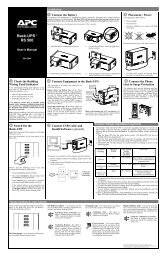
APC Smart-UPS - RIT
APC Smart-UPS - RIT
APC Smart-UPS - RIT

Create successful ePaper yourself
Turn your PDF publications into a flip-book with our unique Google optimized e-Paper software.
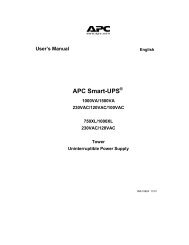
User Manual English<br />
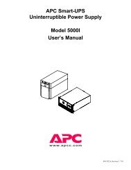
<strong>APC</strong> <strong>Smart</strong>-<strong>UPS</strong> ®<br />
2200/3000 VA<br />
100/120/230 VAC<br />
Tower<br />
Uninterruptible Power Supply<br />
990-1674C 12/20005
Introduction<br />
About this <strong>UPS</strong><br />
Introduction<br />
The <strong>APC</strong> Uninterruptible Power Supply (<strong>UPS</strong>) is designed to prevent utility power blackouts, brownouts, sags<br />
and surges from reaching your electronic equipment. The uninterruptible power supply (<strong>UPS</strong>) filters small<br />
utility line fluctuations and isolates your electronic equipment from large disturbances by internally<br />
disconnecting from the utility line. The <strong>UPS</strong> provides continuous power from the internal battery until utility<br />
power returns to safe levels or the battery is fully discharged.<br />
Installation<br />
Unpack<br />
Read the Safety Guide before installing the <strong>UPS</strong>.<br />
Inspect the <strong>UPS</strong> upon receipt. Notify the carrier and dealer if there is damage.<br />
The packaging is recyclable; save it for reuse or dispose of it properly.<br />
Check the package contents:<br />
• <strong>UPS</strong><br />
• EPO connector<br />
• <strong>UPS</strong> literature kit<br />
containing:<br />
– product documentation<br />
– safety information<br />
– warranty information<br />
Position the <strong>UPS</strong> in the Specified Environment<br />
The <strong>UPS</strong> is heavy. Select a location sturdy enough to handle the weight.<br />
Do not operate the <strong>UPS</strong> where there is excessive dust or the temperature or humidity are outside the specified<br />
limits:<br />
1” (2.5 cm)<br />
0 -<br />
40 C<br />
120/230 V models:<br />
<strong>UPS</strong> literature kit additional contents:<br />
• <strong>Smart</strong>-<strong>UPS</strong>® User<br />
Manuals CD<br />
• PowerChute® CD<br />
• Serial and USB<br />
communication cables<br />
40°C<br />
0°C<br />
0% - 95%<br />
230V models:<br />
<strong>UPS</strong> literature kit additional contents:<br />
• input power cord<br />
• alternate input power<br />
cord (UK customers)<br />
• utility connector plug<br />
• IEC jumper cables<br />
<strong>Smart</strong>-<strong>UPS</strong> 2200/3000 VA 100/120/230 VAC Tower User Manual 3
Installation<br />
Connect the Battery Module<br />
Insert the battery connector into the battery jack and push firmly, twice. You will feel a snap as the<br />
connector partially engages the jack. Push firmly a second time. You will feel a second snap as the<br />
connector securely seats in the battery jack.<br />
4 <strong>Smart</strong>-<strong>UPS</strong> 2200/3000 VA 100/120/230 VAC Tower User Manual
Start Up<br />
Connect Equipment and Power to the <strong>UPS</strong><br />
Start Up<br />
1. The <strong>UPS</strong> features a transient voltage surge-suppression (TVSS) screw located on the rear panel, for<br />
connecting the ground lead on surge suppression devices such as telephone and network line protectors.<br />
Prior to connecting the grounding cable, ensure that the <strong>UPS</strong> is NOT connected to utility or battery<br />
power.<br />
2. Connect equipment to the <strong>UPS</strong>.<br />
3. Add optional accessories to the <strong>Smart</strong>-Slot.<br />
4. Plug the <strong>UPS</strong> into a two-pole, three-wire, grounded receptacle only. Avoid using extension cords.<br />
– 230 V models: The utility power cord is supplied in the <strong>UPS</strong> literature kit. Prior to connecting the<br />
utility power, connect the ground lead (optional) to the TVSS screw.<br />
5. 120 V models: Check the SITE WIRING FAULT LED located on the rear panel. It will be<br />
illuminated if the <strong>UPS</strong> is plugged into an improperly wired utility power outlet, (see Troubleshooting).<br />
6. Turn on all connected equipment. To use the <strong>UPS</strong> as a master on/off switch. Be sure all connected<br />
equipment is switched on.<br />
Rear Panels<br />
100/120 VAC 2200 VA 100/120 VAC 3000 VA 230 VAC 2200/3000 VA<br />
Start the <strong>UPS</strong><br />
1. Press the button on the front panel to start the <strong>UPS</strong>.<br />
– The battery charges to 90% capacity during the first four hours of normal operation. Do not<br />
expect full battery run capability during this initial charge period.<br />
– Refer to the <strong>APC</strong> Web site, www.apc.com for battery runtimes.<br />
2. For optimal computer system security, install PowerChute <strong>Smart</strong>-<strong>UPS</strong> monitoring software.<br />
<strong>Smart</strong>-<strong>UPS</strong> 2200/3000 VA 100/120/230 VAC Tower User Manual 5
Start Up<br />
Connect the <strong>UPS</strong> to the Network (if Applicable)<br />
Communication Ports<br />
SERIAL PORT USB PORT 120/230 V models: Use only the supplied cable to connect to the serial<br />
port. A standard serial interface cable is incompatible with the <strong>UPS</strong>.<br />
100 V models: Users may purchase software and cables as an<br />
accessory to the <strong>UPS</strong>. Refer to the <strong>APC</strong> Web site, www.apc.com for<br />
information on accessories.<br />
Serial and USB ports cannot be used simultaneously.<br />
Emergency Power Off<br />
The emergency power off (EPO) feature is user configurable. EPO provides immediate de-energizing of<br />
connected equipment from a remote location, without switching to battery operation.<br />
1. Use the EPO connector supplied with the <strong>UPS</strong>.<br />
2. Use a normally-open contact to connect the +24 terminal to the IN terminal.<br />
3. Wire the four-pin connector to the EPO system.<br />
EPO PORT<br />
(located on rear panel)<br />
EPO<br />
Connector<br />
The EPO interface is a Safety Extra Low Voltage (SELV) circuit. Connect it only to other SELV<br />
circuits. The EPO interface monitors circuits that have no determined voltage potential. Such closure<br />
circuits may be provided by a switch or relay properly isolated from the utility. To avoid damage to the<br />
<strong>UPS</strong>, do not connect the EPO interface to any circuit other than a closure type circuit.<br />
Use one of the following cable types to connect the <strong>UPS</strong> to the EPO switch.<br />
• CL2: Class 2 cable for general use.<br />
• CL2P: Plenum cable for use in ducts, plenums, and other spaces used for environmental air.<br />
• CL2R: Riser cable for use in a vertical run in a floor-to-floor shaft.<br />
• CLEX: Limited use cable for use in dwellings and for use in raceways.<br />
• For installation in Canada: Use only CSA certified, type ELC, (extra-low voltage control cable).<br />
• For installation in other countries: Use standard low-voltage cable in accordance with national and<br />
local regulations.<br />
6 <strong>Smart</strong>-<strong>UPS</strong> 2200/3000 VA 100/120/230 VAC Tower User Manual
Operation<br />
Display Panels<br />
Display Panel Indicators and Function Buttons<br />
Indicator<br />
LED<br />
Indicator Title Description<br />
On Line The <strong>UPS</strong> is supplying utility power to the connected equipment,<br />
(see Troubleshooting).<br />
AVR Trim The <strong>UPS</strong> is compensating for a high utility voltage.<br />
AVR Boost The <strong>UPS</strong> is compensating for a low utility voltage.<br />
On Battery The <strong>UPS</strong> is supplying battery power to the connected equipment.<br />
Operation<br />
Overload The connected equipment is drawing more than the <strong>UPS</strong> power rating allows,<br />
(see Troubleshooting).<br />
Replace Battery/Battery<br />
Disconnected<br />
120 V models<br />
100/230 V models<br />
Load /<br />
Battery<br />
Charge<br />
The battery is disconnected or must be replaced, (see Troubleshooting).<br />
<strong>Smart</strong>-<strong>UPS</strong> 2200/3000 VA 100/120/230 VAC Tower User Manual 7
Operation<br />
Battery<br />
Charge<br />
Feature<br />
Button<br />
Diagnostic Utility<br />
Voltage<br />
The <strong>UPS</strong> has a diagnostic feature that indicates the utility voltage.<br />
The <strong>UPS</strong> starts a self-test as part of this procedure. The self-test does not<br />
affect the voltage display.<br />
Press and hold the button to view the utility voltage bar graph indicator.<br />
After a few seconds, this five-LED Battery Charge indicator on the<br />
right of the display panel will show the utility input voltage.<br />
Refer to the figure on the left for the voltage reading, (values are not listed on<br />
the <strong>UPS</strong>).<br />
The indicator on the <strong>UPS</strong> shows the voltage is between the displayed value<br />
on the list and the next higher value, (see Troubleshooting).<br />
Feature Title Function<br />
Power On Press this button to turn on the <strong>UPS</strong>. Continue reading for additional<br />
capabilities.<br />
Power Off Press this button to turn off the <strong>UPS</strong>.<br />
Self-Test Automatic: The <strong>UPS</strong> performs a self-test automatically when tuned on, and<br />
every two weeks thereafter (by default). During the self-test, the <strong>UPS</strong><br />
briefly operates the connected equipment on battery.<br />
Cold Start<br />
120/230 V Models<br />
Manual: Press and hold the button for a few seconds to initiate the<br />
self-test.<br />
When there is no utility power and the <strong>UPS</strong> is off, the cold start feature will<br />
switch the <strong>UPS</strong> and connected equipment onto battery power,<br />
(see Troubleshooting).<br />
8 <strong>Smart</strong>-<strong>UPS</strong> 2200/3000 VA 100/120/230 VAC Tower User Manual
Configuration<br />
<strong>UPS</strong> settings<br />
Settings are adjusted through PowerChute software or optional <strong>Smart</strong> Slot accessory cards.<br />
Function<br />
Automatic<br />
Self-Test<br />
Factory<br />
Default<br />
Every 14 days<br />
(336 hours)<br />
User Selectable<br />
Choices Description<br />
• Every 7 days<br />
(168 hours)<br />
• On start up only<br />
• No self-test<br />
<strong>UPS</strong> ID <strong>UPS</strong>_IDEN Up to eight characters<br />
(alphanumeric)<br />
Date of Last<br />
Battery<br />
Replacement<br />
Minimum Capacity<br />
Before Return from<br />
Shutdown<br />
Voltage Sensitivity<br />
The <strong>UPS</strong> detects<br />
and reacts to line<br />
voltage distortions<br />
by transferring to<br />
battery operation to<br />
protect the<br />
connected<br />
equipment.<br />
Alarm Delay<br />
Control<br />
Manufacture<br />
Date<br />
0 percent • 0%<br />
•15%<br />
•30%<br />
•45%<br />
Configuration<br />
Set the interval at which the <strong>UPS</strong> will execute a<br />
self-test.<br />
Uniquely identify the <strong>UPS</strong>, (i.e. server name or<br />
location) for network management purposes.<br />
mm/dd/yy Reset this date when you replace the battery<br />
module.<br />
•50%<br />
•60%<br />
•75%<br />
•90%<br />
High sensitivity Brightly<br />
illuminated: high<br />
sensitivity<br />
Dimly illuminated:<br />
medium sensitivity<br />
No illumination:<br />
low sensitivity<br />
Enable • Enable<br />
•Mute<br />
•Disable<br />
Shutdown Delay 90 seconds • 0 s<br />
•90 s<br />
•180 s<br />
•270 s<br />
• 360 s<br />
• 450 s<br />
• 540 s<br />
• 630 s<br />
Specify the percentage to which batteries will<br />
be charged following a low battery shutdown<br />
before powering connected equipment.<br />
Adjust by pressing the VOLTAGE SENSITIVIY<br />
switch (rear panel). Use a pointed object,<br />
(such as a pen) to do so.<br />
Note: In situations of poor power quality, the<br />
<strong>UPS</strong> may frequently transfer to battery<br />
operation. If the connected equipment can<br />
operate normally under such conditions, reduce<br />
the sensitivity setting to conserve battery<br />
capacity and service life.<br />
Mute ongoing alarms or disable all alarms<br />
permanently.<br />
Set the interval between the time when the <strong>UPS</strong><br />
receives a shutdown command and actual<br />
shutdown.<br />
<strong>Smart</strong>-<strong>UPS</strong> 2200/3000 VA 100/120/230 VAC Tower User Manual 9
Configuration<br />
Function<br />
Low Battery<br />
Warning<br />
Synchronized<br />
Turn-on Delay<br />
Factory<br />
Default<br />
2 minutes<br />
PowerChute<br />
software<br />
interface<br />
provides<br />
automatic,<br />
unattended<br />
shutdown when<br />
approximately<br />
two minutes of<br />
battery operated<br />
run time<br />
remains.<br />
0 seconds • 0 s<br />
•60 s<br />
•120 s<br />
•180 s<br />
High Transfer Point 100 V models:<br />
108 VAC<br />
120 V models:<br />
127 VAC<br />
230 V models:<br />
253 VAC<br />
Low Transfer Point 100 V models:<br />
92 VAC<br />
120 V models:<br />
106 VAC<br />
230 V models:<br />
208 VAC<br />
Brightly<br />
illuminated:<br />
low battery warning<br />
level of about 2 minutes<br />
Dimly illuminated:<br />
low battery<br />
warning level of about<br />
5 minutes<br />
No illumination:<br />
low battery warning<br />
level is about 8 minutes<br />
•108 VAC<br />
•110 VAC<br />
•127 VAC<br />
•130 VAC<br />
•253 VAC<br />
•257 VAC<br />
•86 VAC<br />
•88 VAC<br />
•97 VAC<br />
•100 VAC<br />
•196 VAC<br />
•200 VAC<br />
• 240 s<br />
• 300 s<br />
• 360 s<br />
• 420 s<br />
•112 VAC<br />
•114 VAC<br />
• 133 VAC<br />
• 136 VAC<br />
• 261 VAC<br />
• 265 VAC<br />
•90 VAC<br />
•92 VAC<br />
• 103 VAC<br />
• 106 VAC<br />
• 204 VAC<br />
• 208 VAC<br />
Output Voltage<br />
230 V models 230 VAC • 220 VAC • 240 VAC<br />
User Selectable<br />
Choices Description<br />
The low-battery warning beeps are continuous<br />
when two minutes of run time remain.<br />
To change the default interval setting, use a<br />
pointed object such as a pen to press the<br />
VOLTAGE SENSITIVIY switch (rear<br />
panel), while<br />
pressing the button, (front display).<br />
Change the low battery warning interval setting<br />
to the time that the operating system or system<br />
software requires to safely shut down.<br />
Specify the time the <strong>UPS</strong> will wait after the<br />
return of utility power before start up, (to avoid<br />
branch circuit overload).<br />
To avoid unnecessary use of the battery where<br />
utility voltage is chronically high, set the high<br />
transfer point higher if the connected<br />
equipment can tolerate this condition.<br />
To avoid unnecessary use of the battery where<br />
utility voltage is chronically low, set the low<br />
transfer point lower if the connected equipment<br />
can tolerate this condition.<br />
230 V models only: Sets the output voltage of<br />
the <strong>UPS</strong>.<br />
10 <strong>Smart</strong>-<strong>UPS</strong> 2200/3000 VA 100/120/230 VAC Tower User Manual
Storage, Maintenance, Transport, and Service<br />
Storage<br />
Store the <strong>UPS</strong> covered in a cool, dry location with the batteries fully charged.<br />
At 5° to 86° F (–15° to 30° C), charge the <strong>UPS</strong> battery every six months.<br />
At 86° to 113° F (30° to 45° C), charge the <strong>UPS</strong> battery every three months.<br />
Storage, Maintenance, Transport, and Service<br />
Replacing the Battery Module<br />
This <strong>UPS</strong> has an easy-to-replace, hot-swappable battery module. Replacement is a safe procedure, isolated<br />
from electrical hazards. You may leave the <strong>UPS</strong> and connected equipment on during the replacement<br />
procedure.<br />
Once the batteries are disconnected the connected equipment is not protected from power outages.<br />
Refer to the appropriate replacement battery user manual for battery module installation instructions. See your<br />
dealer or contact <strong>APC</strong> at www.apc.com/support for information on replacement battery modules.<br />
Service<br />
Be sure to deliver the spent battery(s) to a recycling facility or ship it to <strong>APC</strong> in the<br />
replacement battery packing material.<br />
If the <strong>UPS</strong> requires service do not return it to the dealer. Follow these steps:<br />
1. Review the problems discussed in Troubleshooting to eliminate common problems.<br />
2. If the problem persists, contact <strong>APC</strong> Customer Service through the <strong>APC</strong> Web site,<br />
www.apc.com/support.<br />
– Note the model number of the <strong>UPS</strong>, the serial number, and the date purchased. If you call <strong>APC</strong><br />
Customer Service, a technician will ask you to describe the problem and attempt to solve it over<br />
the phone. If this is not possible, the technician will issue a Returned Material Authorization<br />
Number (RMA#).<br />
– If the <strong>UPS</strong> is under warranty, repairs are free.<br />
– Procedures for servicing or returning products may vary internationally. Refer to the <strong>APC</strong> Web<br />
site for country specific instructions.<br />
3. Pack the <strong>UPS</strong> in its original packaging. If this is not available, refer to www.apc.com/support for<br />
information about obtaining a new set.<br />
– Pack the <strong>UPS</strong> properly to avoid damage in transit. Never use Styrofoam beads for packaging.<br />
Damage sustained in transit is not covered under warranty.<br />
– Always DISCONNECT THE BATTERY before shipping in compliance with U.S.<br />
Department of Transportation (DOT) and IATA regulations. The battery may remain in the<br />
<strong>UPS</strong>.<br />
4. Mark the RMA# on the outside of the package.<br />
5. Return the <strong>UPS</strong> by insured, prepaid carrier to the address given to you by Customer Service.<br />
<strong>Smart</strong>-<strong>UPS</strong> 2200/3000 VA 100/120/230 VAC Tower User Manual 11
Troubleshooting<br />
Troubleshooting<br />
Use this chart to solve minor <strong>UPS</strong> installation and operation problems. Refer to www.apc.com with complex<br />
<strong>UPS</strong> problems.<br />
Problem and/or Possible Cause Solution<br />
<strong>UPS</strong> will not turn on<br />
The battery is not connected properly. Check that the battery connector is fully engaged.<br />
button not pushed. Press the button once to power-up the <strong>UPS</strong> and connected equipment.<br />
The <strong>UPS</strong> is not connected to utility<br />
power supply.<br />
Check that the power cable from the <strong>UPS</strong> to the utility power supply is<br />
securely connected at both ends.<br />
Very low or no utility voltage Check the utility power supply to the <strong>UPS</strong> by plugging in a table lamp. If the<br />
light is very dim, have the utility voltage checked.<br />
<strong>UPS</strong> will not turn off<br />
The <strong>UPS</strong> is experiencing an internal<br />
fault<br />
<strong>UPS</strong> beeps occasionally<br />
Normal <strong>UPS</strong> operation when running<br />
on battery.<br />
<strong>UPS</strong> is not providing expected backup time<br />
The <strong>UPS</strong> battery(s) are weak due to a<br />
recent power outage or battery(s) are<br />
near the end of their service life.<br />
All LEDs are illuminated and the <strong>UPS</strong> emits a constant beeping<br />
The <strong>UPS</strong> is experiencing an internal<br />
fault.<br />
Front panel LEDs flash sequentially<br />
The <strong>UPS</strong> has been shut down remotely<br />
through software or an optional<br />
accessory card.<br />
Do not attempt to use the <strong>UPS</strong>. Unplug the <strong>UPS</strong> and have it serviced<br />
immediately.<br />
None: The <strong>UPS</strong> is protecting the connected equipment. Press the button<br />
to silence this alarm.<br />
Charge the battery(s). Batteries require recharging after extended outages.<br />
Batteries can wear faster when put into service often or when operated at<br />
elevated temperatures. If the battery(s) are near the end of their service life,<br />
consider replacing the battery(s) even if the replace battery LED is not yet<br />
illuminated.<br />
Do not attempt to use the <strong>UPS</strong>. Unplug the <strong>UPS</strong> and have it serviced<br />
immediately.<br />
None: The <strong>UPS</strong> will restart automatically when utility power returns.<br />
12 <strong>Smart</strong>-<strong>UPS</strong> 2200/3000 VA 100/120/230 VAC Tower User Manual
Problem and/or Possible Cause Solution<br />
All LEDs are off and the <strong>UPS</strong> is plugged into a wall outlet<br />
The <strong>UPS</strong> is shut down or the battery is<br />
discharged from an extended outage.<br />
The Overload LED is illuminated and the <strong>UPS</strong> emits a sustained alarm tone<br />
Troubleshooting<br />
None: The <strong>UPS</strong> will restart automatically when utility power is restored and<br />
the battery has a sufficient charge.<br />
The <strong>UPS</strong> is overloaded. The connected equipment exceeds the specified “maximum load” as defined<br />
in Specifications on the <strong>APC</strong> Web site, www.apc.com.<br />
The alarm remains on until the overload is removed. Disconnect nonessential<br />
equipment from the <strong>UPS</strong> to eliminate the overload condition.<br />
The <strong>UPS</strong> continues to supply power as long as it is online and the circuit<br />
breaker does not trip; the <strong>UPS</strong> will not provide power from batteries in the<br />
event of a utility voltage interruption.<br />
The Replace Battery/Battery Disconnected LED is illuminated<br />
The Replace Battery/Battery<br />
Disconnected LED flashes and a short<br />
beep is emitted every two seconds to<br />
indicate the battery is disconnected.<br />
Check that the battery connectors are fully engaged.<br />
Weak battery Allow the battery to recharge for 24 hours and perform a self-test. If the<br />
problem persists after recharging, replace the battery.<br />
Failure of a battery self-test: Replace<br />
Battery/Battery Disconnected LED<br />
illuminates and the <strong>UPS</strong> emits short<br />
beeps for one minute. The <strong>UPS</strong> repeats<br />
the alarm every five hours.<br />
Allow the battery to recharge for 24 hours. Perform the self-test procedure to<br />
confirm the replace battery condition. The alarm stops and the LED clears if<br />
the battery passes the self-test.<br />
If the battery fails again, it must be replaced. The connected equipment is<br />
unaffected.<br />
The Site Wiring Fault LED on the rear panel is illuminated (120 V model only)<br />
The <strong>UPS</strong> is plugged into an improperly<br />
wired utility power outlet.<br />
The input circuit breaker trips<br />
The connected equipment exceeds the<br />
specified “maximum load” as defined<br />
in Specifications on the <strong>APC</strong> Web site,<br />
www.apc.com.<br />
The AVR Boost or AVR Trim LEDs are illuminated<br />
The system is experiencing very high or<br />
low utility voltage.<br />
Wiring faults detected include missing ground, hot-neutral polarity reversal,<br />
and overloaded neutral circuit.<br />
Contact a qualified electrician to correct the building wiring.<br />
Unplug all nonessential equipment from the <strong>UPS</strong>.<br />
Reset the circuit breaker.<br />
Have a qualified service personnel check your facility for electrical<br />
problems. If the problem persists, contact the utility company for further<br />
assistance.<br />
<strong>Smart</strong>-<strong>UPS</strong> 2200/3000 VA 100/120/230 VAC Tower User Manual 13
Troubleshooting<br />
Problem and/or Possible Cause Solution<br />
There is no utility power<br />
There is no utility power and the <strong>UPS</strong> is<br />
off.<br />
<strong>UPS</strong> operates on battery although line voltage exists<br />
120/230 V models: Use the cold start feature to supply power to the<br />
connected equipment front the <strong>UPS</strong> battery(s).<br />
Press the button for one second and release. The <strong>UPS</strong> will beep briefly.<br />
Press and hold the button again for about three seconds. The unit will<br />
emit two beeps. Release the button during the second beep.<br />
The <strong>UPS</strong> input circuit breaker trips. Unplug all nonessential equipment from the <strong>UPS</strong>.<br />
Reset the circuit breaker.<br />
Your system is experiencing very high,<br />
low or distorted line voltage.<br />
Battery Charge and Load LEDs flash simultaneously<br />
The <strong>UPS</strong> has shut down.<br />
The internal temperature of the <strong>UPS</strong> has<br />
exceeded the allowable threshold for<br />
safe operation.<br />
Diagnostic utility voltage<br />
Move the <strong>UPS</strong> to a different outlet on a different circuit: Inexpensive fuel<br />
powered generators may distort the voltage. Test the input voltage with the<br />
utility voltage display, (see Operation). If acceptable to the connected<br />
equipment, reduce the <strong>UPS</strong> sensitivity.<br />
Check that the room temperature is within the specified limits for operation.<br />
Check that the <strong>UPS</strong> is properly installed, allowing for adequate ventilation.<br />
Allow the <strong>UPS</strong> to cool down. Restart the <strong>UPS</strong>. If the problem persists,<br />
contact <strong>APC</strong> at www.apc.com.<br />
All five LEDs are illuminated. The line voltage is extremely high and should be checked by an electrician.<br />
There is no LED illumination. The line voltage is extremely high and should be checked by an electrician.<br />
On Line LED<br />
There is no LED illumination. The <strong>UPS</strong> is running on battery, or it must be turned on.<br />
The LED is blinking. The <strong>UPS</strong> is running an internal self-test.<br />
14 <strong>Smart</strong>-<strong>UPS</strong> 2200/3000 VA 100/120/230 VAC Tower User Manual
Regulatory and Warranty Information<br />
Regulatory Agency Approvals and Radio Frequency Warnings<br />
Regulatory and Warranty Information<br />
FCC Compliance Notice<br />
This equipment has been tested and found to comply with the limits for a Class A digital device, pursuant to<br />
part 15 of the FCC Rules. These limits are designed to provide reasonable protection against harmful<br />
interference when the equipment is operated in a commercial environment. This equipment generates, uses,<br />
and can radiate radio frequency energy. If it is not installed and used in accordance with the instruction<br />
manual, it may cause harmful interference to radio communications. Operation of this equipment in a<br />
residential area is likely to cause harmful interference in which case users will be required to take whatever<br />
measures may be necessary to correct the interference at their own expense.<br />
120 V models<br />
100 V models<br />
230 V models<br />
®<br />
LISTED 42C2<br />
E95463<br />
®<br />
LISTED 42C2<br />
E95463<br />
LR 63938<br />
geprüfte<br />
Sicherheit<br />
N394 ME 61<br />
BSMI<br />
T3A031<br />
<strong>Smart</strong>-<strong>UPS</strong> 2200/3000 VA 100/120/230 VAC Tower User Manual 15
Regulatory and Warranty Information<br />
EN62040-1-1; EN55022; EN55024;<br />
EN61000-3-2, 3-3, 4-2, 4-4, 4-5, 4-6, 4-8, 4-11;<br />
EN60950; IEC60950-1<br />
73/23/EEC; 93/68/EEC<br />
PowerSupply<br />
SUA2200I; SUA3000I<br />
American Power Conversion<br />
Ballybritt Business Park<br />
Galway, Ireland<br />
Galway, Ireland<br />
N. Billerica, MA<br />
USA<br />
Limited Warranty<br />
American Power Conversion (A.P.C.)<br />
Ballybritt Business Park.<br />
Galway, Ireland<br />
American Power Conversion<br />
132 Fairgrounds Rd.<br />
West Kingston, RI 02892 USA<br />
<strong>APC</strong> (Suzhou) <strong>UPS</strong> Co.,Ltd<br />
339 Suhong Zhong Lu<br />
Suzhou Industrial Park<br />
Suzhou Jiangau 2215021<br />
P. R. China<br />
<strong>APC</strong> India Pvt, Ltd.<br />
187/3, 188/3, Jigani Industrial Area<br />
Bangaldore, 562106<br />
Kanataka<br />
India<br />
Date of product declaration<br />
American Power Conversion<br />
Lot 3, Block 14, Phase 3<br />
PEZA, Rosario, Cavite<br />
Philippines<br />
American Power Conversion<br />
2nd Street<br />
PEZA, Cavite Economic Zone<br />
Rosario, Cavite<br />
Philippines<br />
American Power Conversion<br />
Lot 10, Block 16, Phase 4<br />
PEZA, Rosario, Cavite<br />
Philippines<br />
<strong>APC</strong> Brasil LTDA.<br />
AI.Xingu, 850<br />
Barueri<br />
Alphaville/Sao Paulo<br />
06455-030<br />
Brazil<br />
American Power Conversion (<strong>APC</strong>) warrants its products to be free from defects in materials and workmanship for a period of two years<br />
from the date of purchase. Its obligation under this warranty is limited to repairing or replacing, at its own sole option, any such defective<br />
products. To obtain service under warranty you must obtain a Returned Material Authorization (RMA) number from customer support.<br />
Products must be returned with transportation charges prepaid and must be accompanied by a brief description of the problem encountered<br />
and proof of date and place of purchase. This warranty does not apply to equipment that has been damaged by accident, negligence, or<br />
misapplication or has been altered or modified in any way. This warranty applies only to the original purchaser who must have properly<br />
registered the product within 10 days of purchase.<br />
EXCEPT AS PROVIDED HEREIN, AMERICAN POWER CONVERSION MAKES NO WARRANTIES, EXPRESSED OR IMPLIED,<br />
INCLUDING WARRANTIES OF MERCHANTABILITY AND FITNESS FOR A PARTICULAR PURPOSE. Some states do not permit<br />
limitation or exclusion of implied warranties; therefore, the aforesaid limitation(s) or exclusion(s) may not apply to the purchaser.<br />
EXCEPT AS PROVIDED ABOVE, IN NO EVENT WILL <strong>APC</strong> BE LIABLE FOR DIRECT, INDIRECT, SPECIAL, INCIDENTAL, OR<br />
CONSEQUENTIAL DAMAGES ARISING OUT OF THE USE OF THIS PRODUCT, EVEN IF ADVISED OF THE POSSIBILITY OF<br />
SUCH DAMAGE. Specifically, <strong>APC</strong> is not liable for any costs, such as lost profits or revenue, loss of equipment, loss of use of equipment,<br />
loss of software, loss of data, costs of substitutes, claims by third parties, or otherwise.<br />
16 <strong>Smart</strong>-<strong>UPS</strong> 2200/3000 VA 100/120/230 VAC Tower User Manual
<strong>APC</strong> Worldwide Customer Support<br />
Customer support for this or any other <strong>APC</strong> product is available at no charge in any of the following ways:<br />
• Refer to the <strong>APC</strong> Web site to access documents in the <strong>APC</strong> Knowledge Base and to submit customer<br />
support requests.<br />
– www.apc.com (Corporate Headquarters)<br />
Connect to localized <strong>APC</strong> Web sites for specific countries, each of which provides customer<br />
support information.<br />
– www.apc.com/support/<br />
Global support searching <strong>APC</strong> Knowledge Base and using e-support.<br />
• Contact an <strong>APC</strong> Customer Support center by telephone or e-mail.<br />
Local, country-specific centers:<br />
go to www.apc.com/support/contact for information.<br />
Contact the <strong>APC</strong> representative or other distributor from whom you purchased your <strong>APC</strong> product for<br />
information on how to obtain local customer support.<br />
Entire contents copyright 2005 American Power Conversion Corporation. All rights reserved. Reproduction in whole or in part without<br />
permission is prohibited.<br />
<strong>APC</strong>, the <strong>APC</strong> logo, <strong>Smart</strong>-<strong>UPS</strong> and PowerChute are trademarks of American Power Conversion Corporation All other trademarks,<br />
product names, and corporate names are the property of their respective owners and are used for informational purposes only.<br />
<strong>Smart</strong>-<strong>UPS</strong> 2200/3000 VA 100/120/230 VAC Tower User Manual 17