
Create successful ePaper yourself
Turn your PDF publications into a flip-book with our unique Google optimized e-Paper software.
User Manual English<br />
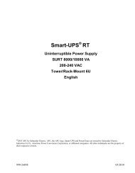
<strong>APC</strong> <strong>APC</strong> <strong>Smart</strong> <strong>Smart</strong>-UPS <strong>Smart</strong> UPS<br />
UPS ® <strong>RT</strong><br />
<strong>RT</strong><br />
7500/10000 7500/10000 VA VA 200 200-240 200 240 VAC VAC 6U<br />
Tower/Rack Tower/Rack Mount Mount<br />
Mount<br />
Uninterruptible Uninterruptible Power Power Supply<br />
Supply<br />
990-1216B 02/2004
Introduction<br />
The <strong>APC</strong> <strong>Smart</strong>-UPS <strong>RT</strong> is a high-performance, uninterruptible power system (UPS), designed to<br />
prevent blackouts, brownouts, sags and surges from reaching your computers, servers, and other<br />
sensitive electronic equipment.<br />
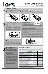
1: INSTALLATION<br />
Attention: Read the safety information sheet before installation.<br />
Unpacking<br />
Inspect the UPS upon receipt. Notify the carrier and dealer if there is damage.<br />
The packaging is recyclable; save it for reuse or dispose of it properly.<br />
Check the package contents:<br />
UPS (with batteries disconnected)<br />
Two front bezels<br />
Literature kit containing:<br />
Software<br />
<strong>Smart</strong>-UPS User Manuals CD<br />
XLI model only: Six output power cords<br />
Serial cable<br />
Product documentation, safety and warranty information<br />
SNMP/Web Card User Manual<br />
Removing the Batteries<br />
The unit is heavy. To lighten the unit, remove the batteries. Refer to the unpacking instructions on<br />
the carton in which the unit is shipped.<br />
Placement<br />
Attention: The UPS is heavy. Select a location sturdy enough to handle the weight.<br />
Do not operate the UPS in excessive dust or in temperature and humidity outside the specified limits.<br />
Ensure the air vents on the front and rear of the UPS are not blocked.<br />
Refer to the <strong>APC</strong> web site, www.apc.com for details.<br />
1
Hardwiring<br />
Attention: Wiring must be performed by a qualified electrician.<br />
1. Install a utility circuit breaker in accordance with local electrical codes (see tables below) for<br />
input wiring only.<br />
2. Switch the UPS input circuit breaker (see A) and utility circuit breakers OFF.<br />
3. Remove the access panel (see B).<br />
4. Remove circular knockouts.<br />
5. Run wires through access panel to terminal blocks. Wire to ground block first. Adhere to all<br />
national and local electrical codes. (See tables and graphics.)<br />
6. Use appropriate glands to achieve strain-relief on the hardwired input and output power cables.<br />
XLT, XLJ, AND XLTW MODELS<br />
Input Connection Output Connection (optional)<br />
Wire to L1, L2, and . Wire to L1A, L2A, and .<br />
System Wiring Voltage Current<br />
Full Load<br />
(Nominal)<br />
SU<strong>RT</strong>7500XLJ,<br />
SU<strong>RT</strong>7500XLT,<br />
SU<strong>RT</strong>7500XLTW<br />
SU<strong>RT</strong>10000XLJ,<br />
SU<strong>RT</strong>10000XLT,<br />
SU<strong>RT</strong>10000XLTW<br />
Input & Output 200/208/220V 40 amps<br />
XLTW- 38 amps<br />
Input & Output 200/208/220V 54 amps<br />
XLTW-50 amps<br />
2<br />
External Input<br />
Circuit Breaker<br />
(typical)<br />
50 amps / 2-pole for<br />
Input Wiring Only<br />
70 amps / 2-pole for<br />
Input Wiring only<br />
XLI MODELS<br />
Input Connections Output Connection (optional)<br />
Single-Phase: Wire to L1, N, and .<br />
Three-Phase: Wire to L1, L2, L3, N, and .<br />
System Wiring Number<br />
of<br />
Phases<br />
SU<strong>RT</strong>7500XLI<br />
SU<strong>RT</strong>10000XLI<br />
Voltage Current<br />
Full Load<br />
(Nominal)<br />
Wire to L1A, N1, and .<br />
External Input<br />
Circuit Breaker<br />
(typical)<br />
Wire Size<br />
(typical)<br />
#8AWG/<br />
10mm 2<br />
#6AWG/<br />
16mm 2<br />
Wire Size<br />
(typical)<br />
Input 1 220/230/240V 38 amps 50 amps / 2-pole 10mm 2<br />
Input 3+<br />
Neutral<br />
380/400/415V 14 amps / phase when<br />
online, 38 amps on L1<br />
in bypass<br />
50 amps / 4-pole 10mm 2<br />
Output 1 220/230/240V 38 amps (not required) 10mm 2<br />
Input 1 220/230/240V 50 amps 63 amps / 2-pole 16mm 2<br />
Input 3+<br />
Neutral<br />
380/400/415V 18 amps / phase when<br />
online, 50 amps on L1<br />
in bypass<br />
63 amps / 4-pole 16mm 2<br />
Output 1 220/230/240V 50 amps (not required) 16mm 2
7. XLI model only: For three-phase input, set the Input Phase Selector switch (see C) to ‘3’. For<br />
single-phase input, leave switch in default position of ‘1’.<br />
8. Switch the circuit breakers ON.<br />
9. Check line voltages.<br />
10. Replace the access panel.<br />
XLT/XLJ/XLTW MODELS<br />
A<br />
XLI MODEL<br />
A<br />
3<br />
OUTPUT<br />
OUTPUT<br />
INPUT<br />
B<br />
INPUT<br />
L1<br />
L1A<br />
N1<br />
L2<br />
L3<br />
C<br />
L1A<br />
L2A<br />
B<br />
L1<br />
L2<br />
N
Installing and Connecting the Batteries and Attaching the Front Bezel<br />
<br />
<br />
<br />
4
CONNECTING POWER AND EQUIPMENT TO THE UPS<br />
1. Hardwire the UPS (see Hardwiring).<br />
2. Connect equipment to the UPS (cables not included for XLT/XLJ/XLTW models).<br />
3. Turn on all connected equipment. To use the UPS as a master on/off switch, be sure that all<br />
connected equipment is switched ON.<br />
4. Press the button on the front panel to power up the UPS.<br />
• The battery charges to 90% capacity during the first three hours of normal operation. Do not<br />
expect full battery run capability during this initial charge period.<br />
5. Configure the Web/SNMP management card (optional).<br />
OPTIONS<br />
Refer to the <strong>APC</strong> web site, www.apc.com for available accessories.<br />
External Battery Pack SU<strong>RT</strong>192XLBP<br />
Rail Kit SU<strong>RT</strong>RK2<br />
Isolation Transformer<br />
Service Bypass Panel<br />
CIRCUIT BREAKERS<br />
Input Circuit Breaker<br />
7500/10000 VA<br />
XLI/XLJ/XLT/XLTW<br />
Output Circuit Breaker<br />
7500/10000 VA<br />
XLJ/XLT/XLTW<br />
Output Circuit Breaker<br />
7500/10000 VA XLI<br />
The UPS is protected from extreme overloads when in ON position.<br />
The breaker must be on for the UPS to operate.<br />
L6-20<br />
250V 20A<br />
IEC 320-C13<br />
10A for each<br />
receptacle<br />
5<br />
L6-30<br />
250V 30A<br />
IEC 320-C19<br />
16A for each<br />
receptacle
BASIC CONNECTORS<br />
Serial Port<br />
Ethernet Port<br />
EPO Terminal<br />
TVSS Screw<br />
External Battery Pack<br />
Connectors<br />
Power management software and interface kits can be used with the<br />
UPS.<br />
Use only interface kits supplied or approved by <strong>APC</strong>.<br />
Connect the UPS to the network.<br />
(Located on Web/SNMP card.)<br />
The optional Emergency Power Off (EPO) feature allows connected<br />
loads to be immediately de-energized from a remote location, without<br />
switching to battery operation (see EPO Option).<br />
The UPS features a transient voltage surge-suppression (TVSS) screw<br />
for connecting the ground lead on surge suppression devices such as<br />
telephone and network line protectors.<br />
When connecting grounding cable, disconnect the unit from the utility<br />
power outlet.<br />
Optional external battery packs provide extended runtime during<br />
power outages. These units support up to 10 external battery packs.<br />
See the <strong>APC</strong> website, www.apc.com/products for the information on<br />
the external battery pack, SU<strong>RT</strong>192XLBP.<br />
6
2: OPERATION<br />
Indicator Description<br />
Online<br />
On Battery<br />
Bypass<br />
Fault<br />
Overload<br />
Replace<br />
Battery<br />
Feature Function<br />
Power On<br />
Power Off<br />
FRONT DISPLAY PANEL<br />
The UPS is drawing utility power and performing double conversion to supply<br />
power to connected equipment (see Troubleshooting).<br />
The UPS is supplying battery power to the connected equipment.<br />
The UPS is in bypass mode, sending utility power directly to connected equipment.<br />
Bypass mode operation is the result of an internal UPS fault, an overload condition<br />
or a user initiated command either through an accessory or the manual bypass<br />
switch. Battery operation is not available while the UPS is in bypass mode (see<br />
Troubleshooting).<br />
The UPS detects an internal fault (see Troubleshooting).<br />
The connected loads are drawing more power than the UPS power rating (see<br />
Troubleshooting).<br />
The battery is disconnected or must be replaced (see Troubleshooting).<br />
Press this button to turn on the UPS. (Read on for additional capabilities.)<br />
Press this button to turn off the UPS.<br />
7
Feature Function<br />
Normal /Bypass<br />
Cold Start<br />
Manually switch connected equipment to bypass mode, so that utility power is<br />
sent directly to connected equipment. Battery operation is not available while<br />
the UPS is in bypass mode. (See Troubleshooting.)<br />
This is not a normal condition.<br />
Supply immediate battery power to the UPS and connected equipment (see<br />
Troubleshooting). Press and hold the button to power up the UPS and<br />
connected equipment. The UPS will emit two beeps. During the second beep,<br />
release the button.<br />
Self-Test Automatic: The UPS performs a self-test automatically when turned on, and<br />
every two weeks thereafter (by default). During the self-test, the UPS briefly<br />
operates the connected equipment on battery.<br />
Diagnostic Utility<br />
Voltage<br />
On Battery Operation<br />
Manual: Press and hold the button for a few seconds to initiate the selftest.<br />
The UPS has a diagnostic feature that displays the utility voltage. Plug the UPS<br />
into the normal utility power.<br />
The UPS starts a self-test as part of this procedure. The self-test does not<br />
affect the voltage display.<br />
Press and hold the button to view the utility voltage bar graph display.<br />
After a few seconds the five-LED, Battery Charge display on the right of<br />
the front panel shows the utility input voltage.<br />
Refer to the figure at left for the voltage reading (values are not listed on the<br />
UPS).<br />
The display indicates the voltage is between the displayed value on the list and<br />
the next higher value.<br />
The UPS switches to battery operation automatically if the utility power fails. While running on<br />
battery, an alarm beeps four times every 30 seconds.<br />
Press the button to silence this alarm. If the utility power does not return, the UPS continues to<br />
supply power to the connected equipment until the battery is fully discharged.<br />
When two minutes of runtime remain the UPS emits a continuous beep. If PowerChute or the<br />
Web/SNMP card is not being used, files must be manually saved and the computer must be properly<br />
shut down before the UPS fully discharges the battery.<br />
The UPS battery life differs based on usage and environment. Refer to www.apc.com/products for<br />
on battery runtimes.<br />
8
3: USER CONFIGURABLE ITEMS<br />
NOTE: SETTINGS ARE MADE THROUGH SUPPLIED POWERCHUTE SOFTWARE, WEB/SNMP CARD, OPTIONAL<br />
SMA<strong>RT</strong> SLOT ACCESSORY CARDS OR TERMINAL MODE.<br />
FUNCTION<br />
FACTORY<br />
DEFAULT<br />
Automatic Self-Test Every 14 days<br />
(336 hours)<br />
USER SELECTABLE<br />
CHOICES<br />
Every 7 days<br />
(168 hours),<br />
Every 14 days<br />
(336 hours),<br />
On Startup Only,<br />
No Self-Test<br />
UPS ID UPS_IDEN Up to eight characters to<br />
define the UPS<br />
Date of Last Battery<br />
Replacement<br />
Minimum Capacity<br />
Before Return from<br />
Shutdown<br />
Alarm Delay After<br />
Line Failure<br />
9<br />
DESCRIPTION<br />
Set the interval at which the<br />
UPS will execute a self-test.<br />
Uniquely identify the UPS, (i.e.<br />
server name or location) for<br />
network management purposes.<br />
Manufacture Date mm/dd/yy Reset this date when you replace<br />
the battery modules.<br />
0 percent 0, 15, 25, 35, 50, 60, 75,<br />
90 percent<br />
5 second delay 5 second delay,<br />
30 second delay,<br />
At Low Battery,<br />
Never<br />
Shutdown Delay 20 seconds 0, 20, 60, 120, 240, 480,<br />
720, 960 seconds<br />
Duration of<br />
Low Battery Warning.<br />
Synchronized Turn-on<br />
Delay<br />
2 minutes<br />
PowerChute<br />
software provides<br />
automatic,<br />
unattended<br />
shutdown when<br />
approximately two<br />
minutes of battery<br />
runtime remains.<br />
2, 5, 7, 10, 12, 15, 18,<br />
20 minutes.<br />
0 seconds 0, 20, 60, 120, 240, 480,<br />
720, 960 seconds<br />
Specify the percentage to which<br />
batteries will be charged<br />
following a low-battery<br />
shutdown before powering<br />
connected equipment.<br />
Mute ongoing alarms or disable<br />
all alarms permanently.<br />
Set the interval between the time<br />
when the UPS receives a<br />
shutdown command and the<br />
actual shutdown.<br />
The low battery warning beeps<br />
become continuous when two<br />
minutes of runtime remains.<br />
Change the warning interval to a<br />
higher setting if the operating<br />
system requires a longer interval<br />
for shutdown.<br />
Specify the time the UPS will<br />
wait after the return of utility<br />
power before turn-on (to avoid<br />
branch circuit overloads).
NOTE: SETTINGS ARE MADE THROUGH SUPPLIED POWERCHUTE SOFTWARE, WEB/SNMP CARD, OPTIONAL<br />
SMA<strong>RT</strong> SLOT ACCESSORY CARDS OR TERMINAL MODE.<br />
FUNCTION<br />
High Bypass Point<br />
FACTORY<br />
DEFAULT<br />
+10% of<br />
output voltage<br />
setting<br />
Low Bypass Point -30% of output<br />
voltage setting<br />
Output Voltage 200 V models:<br />
200 VAC<br />
208 V models:<br />
208 VAC<br />
220V models:<br />
220 VAC<br />
230 V models:<br />
230 VAC<br />
Output Frequency Automatic<br />
(50 ± 3 Hz or<br />
60 ± 3 Hz)<br />
Number of Battery<br />
Packs<br />
USER SELECTABLE<br />
CHOICES<br />
+5%, +10%, +15%,<br />
+20%<br />
10<br />
DESCRIPTION<br />
Maximum voltage that the UPS<br />
will pass to connected<br />
equipment during internal<br />
bypass operation.<br />
-15%, -20%, -25%, -30% Minimum voltage that the UPS<br />
will pass to connected<br />
equipment during internal<br />
bypass operation.<br />
200 V models:<br />
200VAC<br />
208 V models:<br />
200, 208, 220, 230, 240<br />
VAC<br />
220V models:<br />
200, 208, 230, 240 VAC<br />
230 V models:<br />
200, 208, 220, 230, 240<br />
VAC<br />
*Use the voltage setting<br />
applicable to your region.<br />
50 ± 3 Hz,<br />
50 ± 0.1 Hz,<br />
60 ± 3 Hz,<br />
60 ± 0.1 Hz<br />
1 Number of Connected<br />
Batteries (four battery<br />
modules per pack)<br />
Allows the user to select the<br />
UPS output voltage while<br />
online.<br />
Sets the allowable UPS output<br />
frequency. Whenever possible,<br />
the output frequency tracks the<br />
input frequency.<br />
Defines the number of<br />
connected battery packs for<br />
proper runtime prediction.
EPO (Emergency Power Off) Option<br />
The output power can be disabled in an emergency by closing a switch connected to the EPO.<br />
Adhere to national and local electrical codes when wiring.<br />
The switch should be connected in a normally open switch contact. External voltage is not required;<br />
the switch is driven by 12V internal supply. In closed condition, 2mA of current are drawn.<br />
The EPO switch is internally powered by the UPS for use with non-powered switch circuit breakers.<br />
The EPO circuit is considered a Class 2 circuit, (UL, CSA standards) and an SELV circuit (IEC<br />
standard).<br />
EPO<br />
switch<br />
Both Class 2 and SELV circuits must be isolated from all primary circuitry. Do not connect any<br />
circuit to the EPO terminal block unless it can be confirmed that the circuit is Class 2 or SELV.<br />
If circuit standard cannot be confirmed, use a contact closure switch.<br />
Use one of the following cable types to connect the UPS to the EPO switch:<br />
• CL2: Class 2 cable for general use<br />
• CL2P: Plenum cable for use in ducts, plenums, and other spaces used for environmental air.<br />
• CL2R: Riser cable for use in a vertical run in a floor-to-floor shaft.<br />
• CLEX: Limited use cable for use in dwellings and for use in raceways.<br />
• For installation in Canada: Use only CSA certified, type ELC (extra-low voltage control cable).<br />
• For installation in other countries: Use standard low-voltage cable in accordance with local<br />
regulations.<br />
11
Terminal Mode to Configure UPS Parameters<br />
Terminal Mode is a menu driven interface that enables enhanced configuration of the UPS.<br />
Connect the serial cable to the serial port on the back of the UPS.<br />
When using PowerChute ® Network Shutdown software:<br />
1. Open a terminal program. Example: HyperTerminal<br />
• From the Desktop, go to Start => Programs => Accessories => Communication<br />
=>HyperTerminal.<br />
2. Double-click on the HyperTerminal icon.<br />
• Follow the prompts to choose a name and select an icon. Disregard the message, “...must<br />
install a modem,” if it is displayed. Click OK.<br />
• Select the COM port that is connected to your UPS. The port settings are:<br />
bits per second - 2400<br />
data - bits 8<br />
parity - none<br />
stop bit - 1<br />
flow control - none<br />
• Click Enter<br />
3. Example for setting the number of external battery packs (SU<strong>RT</strong>192XLBP):<br />
Once the blank terminal window is open, follow these steps to enter the number of battery packs:<br />
• Press ENTER to initiate terminal mode. Press ENTER multiple times, until the prompt User<br />
Name: is displayed. Follow the prompts. Type slowly, waiting until each character appears<br />
on the screen prior to typing the next character.<br />
Web/SNMP Card defaults:<br />
• User Name: apc<br />
• Password: apc<br />
• Press 1 and ENTER to select Device Manager.<br />
• Select the model by entering the corresponding number, then press ENTER.<br />
• Press 3 and ENTER to select Configuration.<br />
• Press 1 and ENTER to select Battery.<br />
• Press 2 and ENTER to change the Battery Settings.<br />
• Type in the number of external battery packs (four battery modules per pack), then<br />
press ENTER. (Number of packs: 1= internal battery module, 2 = 1<br />
SU<strong>RT</strong>192XLBP, 3 = 2 SU<strong>RT</strong>192XLBP, etc.)<br />
• Press 3 and ENTER to accept the changes.<br />
• Press ESC multiple times (5) to return to the main menu.<br />
• Press 4 and ENTER to log out.<br />
12
4: STORAGE, MAINTENANCE, AND TRANSPO<strong>RT</strong>ING<br />
Storage<br />
Store the UPS covered and positioned as for proper functioning, in a cool, dry location, with the<br />
batteries fully charged. (Batteries must be charged every six months.)<br />
Store at: 0-50,000 ft (0 - 15,000 m)<br />
5°-113° F ( -15 - 45 ° C)<br />
Replacing the Battery Module(s)<br />
This UPS has easy to replace, hot-swappable battery modules. Replacement is a safe procedure,<br />
isolated from electrical hazards. You may leave the UPS and connected equipment on during the<br />
procedure. See your dealer or contact <strong>APC</strong> at the web site, www.apc.com for information on<br />
replacement battery modules.<br />
The battery replacement procedure must include replacing all battery modules in the UPS and<br />
connected external battery pack (s).<br />
Upon battery disconnection, equipment is not protected from power outages.<br />
Use caution when handling heavy battery modules.<br />
Refer to Installing and Connecting the Batteries and Attaching the Front Bezel for battery replacement<br />
procedure; reverse instructions for battery removal.<br />
Be sure to deliver the spent battery to a recycling facility or ship it to <strong>APC</strong> in the<br />
replacement battery packing material.<br />
Transporting the UPS<br />
Always disconnect the battery module(s) before shipping the UPS in compliance with U.S.<br />
Department of Transportation (DOT) regulations.<br />
The battery module(s) may remain in the UPS.<br />
1. Shut down and disconnect any equipment attached to the UPS.<br />
2. Shut down and disconnect the UPS from the power supply.<br />
3. Unplug the battery connectors.<br />
For shipping instructions contact <strong>APC</strong> at the web site, www.apc.com/support/contact.<br />
13
5: TROUBLESHOOTING<br />
Use the table below to solve minor installation and operation problems. Refer to the <strong>APC</strong> web site,<br />
www.apc.com, for assistance with complex UPS problems.<br />
PROBLEM AND POSSIBLE<br />
CAUSE<br />
UPS WILL NOT TURN ON<br />
Batteries are not connected<br />
properly.<br />
14<br />
SOLUTION<br />
Check that the battery connectors are fully engaged.<br />
button not pushed. Press the button once to power the UPS and the connected equipment.<br />
UPS not connected to utility<br />
power supply.<br />
Check that the power cable from the UPS to the utility power supply is securely<br />
connected at both ends.<br />
Very low or no utility voltage. Check the utility power supply to ensure proper voltage at the receptacle.<br />
UPS WILL NOT TURN OFF<br />
button not pushed. Press the button once to turn the UPS off.<br />
Internal UPS fault. Do not attempt to use the UPS. Unplug the UPS and have it serviced<br />
immediately.<br />
UPS BEEPS OCCASIONALLY<br />
Normal UPS operation when<br />
running on battery.<br />
UPS DOES NOT PROVIDE EXPECTED BACKUP TIME<br />
The UPS battery module(s) are<br />
weak due to a recent outage or<br />
are near the end of service life.<br />
FRONT PANEL LEDS FLASH SEQUENTIALLY<br />
The UPS has been shut down<br />
remotely through software or an<br />
optional accessory card.<br />
None. The UPS is protecting the connected equipment.<br />
Charge the battery module(s). Modules require recharging after extended outages<br />
and wear faster when put into service often or when operated at elevated<br />
temperatures. If the battery module(s) are near the end of service life, consider<br />
replacing, even if the Replace Battery LED is not illuminated.<br />
None. The UPS will restart automatically when utility power returns.<br />
ALL LEDS ARE OFF AND THE UPS IS CONNECTED TO UTILITY POWER<br />
The UPS is shut down and the<br />
battery is discharged from an<br />
extended outage.<br />
None. The UPS will return to normal operation when the power is restored and<br />
the battery has a sufficient charge.<br />
BYPASS AND OVERLOAD LEDS ILLUMINATE, UPS EMITS A SUSTAINED ALARM TONE<br />
The UPS is overloaded. The connected equipment exceeds the specified “maximum load” as defined in<br />
Specifications on the <strong>APC</strong> web site, www.apc.com.<br />
The alarm remains on until the overload is removed. Disconnect nonessential<br />
equipment from the UPS to eliminate the overload condition.
PROBLEM AND POSSIBLE<br />
CAUSE<br />
BYPASS LED ILLUMINATES<br />
The bypass switch has been<br />
turned on manually or through<br />
an accessory.<br />
15<br />
SOLUTION<br />
If bypass is the chosen mode of operation, ignore the illuminated LED.<br />
If bypass is not the chosen mode of operation move the bypass switch on the<br />
back of the UPS, to the normal position.<br />
FAULT AND OVERLOAD LEDS ILLUMINATE; UPS EMITS A SUSTAINED ALARM TONE<br />
The UPS has ceased sending<br />
power to connected equipment.<br />
The connected equipment exceeds the specified “maximum load” as defined in<br />
Specifications on the <strong>APC</strong> web site, www.apc.com.<br />
Disconnect nonessential equipment from the UPS to eliminate the overload<br />
condition.<br />
Press the OFF button, then the ON button to restore power to connected<br />
equipment.<br />
FAULT LED ILLUMINATES<br />
Internal UPS fault. Do not attempt to use the UPS. Turn the UPS off and have it serviced<br />
immediately.<br />
REPLACE BATTERY LED ILLUMINATES<br />
Replace Battery LED flashes and Check that the battery connectors are fully engaged.<br />
a short beep is emitted every two<br />
seconds to indicate the battery is<br />
disconnected.<br />
Weak battery. Allow the battery to recharge for 24 hours. Then, perform a self-test. If the<br />
problem persists after recharging, replace the battery.<br />
Failure of a battery self-test. The UPS emits short beeps for one minute and the Replace Battery LED<br />
illuminates. The UPS repeats the alarm every five hours. Perform the self-test<br />
procedure after the battery has charged for 24 hours to confirm the Replace<br />
Battery condition. The alarm stops and the LED clears if the battery passes the<br />
self-test.<br />
UPS OPERATES ON BATTERY ALTHOUGH LINE VOLTAGE EXISTS<br />
Very high, low, or distorted line<br />
voltage. (Inexpensive fuel<br />
powered generators can distort<br />
the voltage.)<br />
Move the UPS to a different line circuit. Test the input voltage with the utility<br />
voltage display.<br />
DIAGNOSTIC UTILITY VOLTAGE<br />
All five LEDs are illuminated. The line voltage is extremely high and should be checked by an electrician.<br />
There is no LED illumination. If the UPS is plugged into a properly functioning utility power outlet, the line<br />
voltage is extremely low.<br />
ONLINE LED<br />
There is no LED illumination. The UPS is running on battery, or it is not turned on.<br />
The LED is blinking. The UPS is running an internal self-test.
Service<br />
If the UPS requires service do not return it to the dealer. Instead, follow these steps:<br />
1. Review the problems discussed in the Troubleshooting section of this manual to eliminate<br />
common problems.<br />
2. If the problem persists, contact <strong>APC</strong> Customer Service through the <strong>APC</strong> web site,<br />
www.apc.com/support.<br />
Note the model number of the UPS, the serial number, and the date purchased. If you call<br />
<strong>APC</strong> Customer Service, a technician will ask you to describe the problem and try to solve it<br />
over the phone, if possible. If this is not possible, the technician will issue a Returned<br />
Material Authorization Number (RMA#).<br />
If the UPS is under warranty, repairs are free. If not, there is a repair charge.<br />
3. Pack the UPS in its original packaging. If the original packing is not available, refer to the <strong>APC</strong><br />
web site, www.apc.com/support, for information about obtaining a new set.<br />
Pack the UPS properly to avoid damage in transit. Never use Styrofoam beads for packaging.<br />
Damage sustained in transit is not covered under warranty.<br />
Always disconnect the battery module(s) before shipping in compliance with U.S.<br />
Department of Transportation (DOT), and IATA regulations.<br />
The battery module(s) may remain in the UPS.<br />
4. Mark the RMA# on the outside of the package.<br />
5. Return the UPS by insured, prepaid carrier to the address given to you by Customer Service.<br />
Contacting <strong>APC</strong><br />
In the USA: Refer to the <strong>APC</strong> web site, www.apc.com/support.<br />
Outside the USA: Refer to the <strong>APC</strong> web site, www.apc.com. Select the appropriate country from<br />
the country selection field. Select the Support tab at the top of the web page.<br />
16
6: REGULATORY AND WARRANTY INFORMATION<br />
Regulatory Agency Approvals and Radio Frequency Warnings<br />
200, 208, 220, 230, 240 V MODELS<br />
This is a Class A product. In a domestic environment this product may cause radio interference, in which case the user may be<br />
required to take corrective actions.<br />
BSMI<br />
This equipment has been tested and found to comply with the limits for a Class A digital device, pursuant<br />
to part 15 of the FCC Rules. These limits are designed to provide reasonable protection against harmful<br />
interference when the equipment is operated in a commercial environment. This equipment generates,<br />
uses, and can radiate radio frequency energy and, if not installed and used in accordance with the<br />
instruction manual, may cause harmful interference to radio communications. Operation of this equipment<br />
in a residential area is likely to cause harmful interference. The user is responsible for correcting the<br />
interference.<br />
Shielded signal cables must be used with this product to ensure compliance with the Class A FCC limits.<br />
17
Declaration of Conformity<br />
18
Limited Warranty<br />
American Power Conversion (<strong>APC</strong>) warrants its products to be free from defects in materials and workmanship for a period of<br />
two years from the date of purchase. Its obligation under this warranty is limited to repairing or replacing, at its own sole<br />
option, any such defective products. To obtain service under warranty you must obtain a Returned Material Authorization<br />
(RMA) number from customer support. Products must be returned with transportation charges prepaid and must be<br />
accompanied by a brief description of the problem encountered and proof of date and place of purchase. This warranty does<br />
not apply to equipment that has been damaged by accident, negligence, or misapplication or has been altered or modified in<br />
any way. This warranty applies only to the original purchaser who must have properly registered the product within 10 days of<br />
purchase.<br />
EXCEPT AS PROVIDED HEREIN, AMERICAN POWER CONVERSION MAKES NO WARRANTIES, EXPRESSED OR<br />
IMPLIED, INCLUDING WARRANTIES OF MERCHANTABILITY AND FITNESS FOR A PA<strong>RT</strong>ICULAR PURPOSE.<br />
Some states do not permit limitation or exclusion of implied warranties; therefore, the aforesaid limitation(s) or exclusion(s)<br />
may not apply to the purchaser.<br />
EXCEPT AS PROVIDED ABOVE, IN NO EVENT WILL <strong>APC</strong> BE LIABLE FOR DIRECT, INDIRECT, SPECIAL,<br />
INCIDENTAL, OR CONSEQUENTIAL DAMAGES ARISING OUT OF THE USE OF THIS PRODUCT, EVEN IF<br />
ADVISED OF THE POSSIBILITY OF SUCH DAMAGE. Specifically, <strong>APC</strong> is not liable for any costs, such as lost profits or<br />
revenue, loss of equipment, loss of use of equipment, loss of software, loss of data, costs of substitutes, claims by third parties,<br />
or otherwise.<br />
Entire contents copyright © 2004 by American Power Conversion Corporation. All rights reserved. Reproduction in whole or<br />
in part without permission is prohibited.<br />
<strong>APC</strong>, <strong>Smart</strong>-UPS, and PowerChute are registered trademarks of American Power Conversion Corporation. All other<br />
trademarks are the property of their respective owners.<br />
19