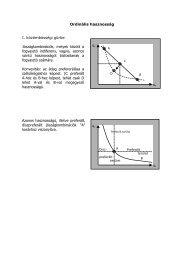
Positioning control systems
Positioning control systems
Positioning control systems

You also want an ePaper? Increase the reach of your titles
YUMPU automatically turns print PDFs into web optimized ePapers that Google loves.
ELGUIDER<br />
Web guiding<br />
<strong>systems</strong><br />
Continuous web position<br />
detection and <strong>control</strong>
Contents<br />
Web guiding <strong>systems</strong> for improved 4<br />
quality and productivity<br />
Control loop 5<br />
Infra-red sensor FR 45 6<br />
Infra-red sensor FR 50 7<br />
Ultrasonic sensor FX 45 8<br />
Ultrasonic sensor FX 40/50 9<br />
Color line sensor FE 50 10<br />
CCD camera OL 81 12<br />
<strong>Positioning</strong> <strong>control</strong> <strong>systems</strong> 14<br />
Sensor positioning VS 45 16<br />
Position <strong>control</strong>ler DC 18<br />
Networking/CANMON 20<br />
Operating panel DO 21<br />
Interfaces DI 22<br />
Data master DM 23<br />
ELGUIDER<br />
Pivoting frame function<br />
24<br />
Pivoting frame system DRS 12 25<br />
Pivoting frame system DRS 22 26<br />
Pivoting frame system DRS 24 27<br />
Pivoting frame system DRS 08 28<br />
Pivoting frame system DRS 09 29<br />
Pivoting frame system DRS 31 30<br />
Pivoting frame system DRS 52 31<br />
Pivoting frame system DRS 71 32<br />
Pivoting frame system DRS 81 33<br />
ELROLLER<br />
Steering roller function<br />
34<br />
Steering roller system VGS 14 35<br />
Steering roller system SRS 31 36<br />
Steering roller system SRS 41 37<br />
Steering roller system SRS 51 38<br />
Steering roller system SRS 61 39<br />
ELTURNER<br />
Turning bar function<br />
40<br />
Turning bar system VWS 41<br />
ELBANDER<br />
Pivoting roller function<br />
42<br />
Pivoting roller system VGA 18 43<br />
Pivoting roller system VGA 19 44<br />
Pivoting roller system VGA 20 45<br />
ELWINDER<br />
Reel station function<br />
46<br />
Actuators, straight version<br />
AG 257/267<br />
47<br />
Actuators, U-version<br />
AG 457/467<br />
48<br />
Actuators, straight version<br />
AG 57/58<br />
49<br />
ELPLACER<br />
Lateral displacement roller function<br />
50<br />
Lateral displacement<br />
roller system SVS 11/21<br />
51<br />
Pneumohydraulic <strong>control</strong>ler 52<br />
Pneumatic sensors 53<br />
Service from A to Z 54
Today, the manufacturers and users of<br />
processing machines for web-type<br />
materials are confronted with ever increasing<br />
demands: production processes<br />
should be even faster, while at<br />
the same time performed with greater<br />
precision, the quality of the finished<br />
product further improved while personnel,<br />
waste and, above all, downtimes,<br />
should be reduced to a minimum.<br />
A decisive contribution in the fulfillment<br />
of these prerequisites is afforded<br />
by web guiding <strong>systems</strong>. Typically,<br />
web-type materials are fed from a reel<br />
to the machine, processed and then<br />
rewound. During these stages, various<br />
position errors may occur, examples<br />
of which are illustrated on this page.<br />
E+L web guiding <strong>systems</strong> are designed<br />
to eliminate these influencing<br />
error variables and to assure permanent,<br />
precision web alignment<br />
and winding. Depending on the type<br />
of material, application and task,<br />
Erhardt+Leimer offer a wide variety<br />
of <strong>systems</strong> with the latest DCS* technology:<br />
for decisively more quality<br />
and productivity that pays off!<br />
* Digital-Control-System<br />
4<br />
Web guiding <strong>systems</strong><br />
for improved quality and<br />
productivity<br />
x<br />
+x<br />
–x<br />
x<br />
x<br />
Typical position errors<br />
Web offset on reel change<br />
On practically all reel changes, the<br />
finished and new web meet with an<br />
offset, causing irregularities in the<br />
following process stage.<br />
Incorrectly wound reels<br />
Fabric reels that are not precisionwound<br />
lead to incorrect web feeding<br />
to the processing machine.<br />
Tumbling errors<br />
Imprecisely adjusted fabric reels tend<br />
to tumble, thus creating a periodical<br />
position error.<br />
Web travel during production<br />
During production mechanical processing,<br />
temperature, humidity or air<br />
currents influence the web and may<br />
effect web travel detrimentally.
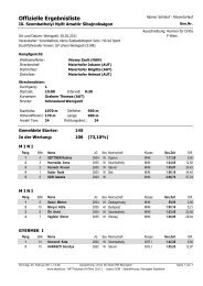
All automated <strong>control</strong> <strong>systems</strong> are<br />
based on the principle of a simple<br />
<strong>control</strong> loop. Even the most complex<br />
of tasks may be reduced to it.<br />
Actuators<br />
Pivoting frame DR<br />
Steering roller SR<br />
Pivoting roller VG<br />
Turning bar VW<br />
Reel station VP<br />
Lateral displacement roller SV<br />
Operating panel DO<br />
Control loop<br />
● Point of departure is the actual web<br />
position.<br />
● A sensor detects the web actual<br />
position without touching. Depending<br />
on the task and fabric properties,<br />
this may be an infra-red, ultrasonic<br />
or line sensor.<br />
Web position<br />
Controller<br />
Digital position <strong>control</strong>ler DC<br />
Pneumatic position <strong>control</strong>ler HP<br />
● The <strong>control</strong>ler compares the actual<br />
web value with the target set value<br />
and transmits the relevant corrective<br />
signal to the actuator.<br />
● The actuator corrects web travel.<br />
Depending on the application and<br />
the fabric type, the actuator may be<br />
a pivoting frame, steering roller,<br />
pivoting roller, turning bar, lateral<br />
displacement roller or linear drive<br />
for reel stations.<br />
Sensors<br />
Infra-red edge sensor FR<br />
Ultrasonic edge sensor FX<br />
Pneumatic edge sensor FL<br />
Color line sensor FE<br />
CCD camera OL<br />
Interface DI<br />
5
Infra-red edge sensor FR 45<br />
This extremely compact digital sensor<br />
operates on a back-light principle.<br />
The transmitter generates a paralled<br />
infra-red light with a wave length of<br />
880 nm which is captured by a CCD<br />
array element in a receiver located<br />
opposite. A processor evaluates the<br />
signals and sends the actual position<br />
value to the CAN bus.<br />
The sensor establishes the edge position<br />
with a precision of 0.01 mm within<br />
a measuring range of +/– 3 mm. A<br />
telecentrical optical unit only evaluates<br />
the parallel light beams. Position<br />
errors due to height fluctuations are<br />
thus excluded.<br />
An automatic exposure <strong>control</strong> permanently<br />
monitors lens soiling and indicates<br />
any soiling to the <strong>control</strong>ler.<br />
Each lens features a blower which<br />
may be connected to the air supply to<br />
deal with soiling such as paper dust<br />
or abraded particles.<br />
6<br />
Infra-red edge sensors<br />
Scan Infrarotsensor<br />
Infra-red sensor FR 45<br />
on a baby diaper machine<br />
Paper<br />
Nonwoven<br />
Rubber<br />
Technical data<br />
Infra-red edge sensor FR 45<br />
Operating voltage<br />
Nominal voltage 24 V DC<br />
Nominal voltage range 20 to 30 V DC<br />
Current rating 110 mA DC<br />
Ambient temperature + 10 to + 50 °C<br />
Measuring range +/– 3 mm<br />
Resolution 0.01 mm (46 pixels x 16 subpixels)<br />
Wave length 880 nm<br />
Scanning rate 200 Hz<br />
Cable length max. 8 m<br />
Protection class IP 54<br />
Weight 0.2 kg<br />
Dimensions (L x W x H) 72 x 27 x 93 mm<br />
Mesh<br />
Textile<br />
Tire cord
Infra-red edge sensor FR 50<br />
The digital edge sensor FR 50 operates<br />
on a retroreflection principle. A<br />
transmitter generates a parallel infrared<br />
light with a wavelength of 880 nm<br />
which is reflected by a prism mirror<br />
located opposite and scanned in the<br />
CCD array element of the receiver. A<br />
processor evaluates the signals and<br />
sends the actual position value to the<br />
CAN bus.<br />
The sensor establishes the edge position<br />
with a precision of 0.02 mm within<br />
a measuring range of +/–10 mm. A<br />
telecentrical optical unit only evaluates<br />
the parallel light beams thus excluding<br />
position errors due to height fluctuations.<br />
An automatic exposure <strong>control</strong> monitors<br />
lens soiling and sends the appropriate<br />
message to the <strong>control</strong>ler in the<br />
event of soiling.<br />
Adaptation for scanning smooth<br />
homogenous or mesh-type web<br />
edges may be conveniently selected<br />
via parameters.<br />
Infra-red edge sensors<br />
Infra-red sensor FR 50<br />
on a rotary offset press<br />
Paper<br />
Nonwoven<br />
Rubber<br />
Technical data<br />
Infra-red edge sensor FR 50<br />
Operating voltage<br />
Nominal voltage 24 V DC<br />
Nominal voltage range 20 to 30 V DC<br />
Current rating 80 mA DC<br />
Ambient temperature + 10 to + 50 °C<br />
Measuring range +/– 10 mm<br />
Resolution 0.02 mm (64 pixels x 16 subpixels)<br />
Wave length 880 nm<br />
Scanning rate 200 Hz<br />
Cable length max. 8 m<br />
Protection class IP 65<br />
Weight 0.3 kg<br />
Dimensions (L x W x H) 105 x 50 x 43 mm<br />
Mesh<br />
Textile<br />
Tire cord<br />
7
Ultrasonic edge sensor FX 45<br />
These digital sensors detect web<br />
edges without touching by ultrasonic<br />
means. As such they are ideally suited<br />
for implementation on paper webs<br />
and with transparent foils. As these<br />
sensors are very small they are<br />
mainly used on small pivoting frames<br />
ELGUIDER DRS 12/22 for narrow<br />
webs.<br />
The transmitter oscillates with an ultrasonic<br />
frequency of 200 kHz which<br />
is output in pulses of 1 kHz. Depending<br />
on the fork gap, the receiver measures<br />
the density of the ultrasonic<br />
waves that are not covered by the<br />
web edge.<br />
Disturbances such as air movement<br />
or temperature fluctuations are compensated<br />
to such an extent that the<br />
edge may be recorded to an accuracy<br />
of 0.1 mm.<br />
The analog ultrasonic sensor signal is<br />
digitalized via a A/D converter and<br />
output on the CAN bus. All calibration<br />
and evaluation processes are also<br />
run digitally.<br />
8<br />
Ultrasonic edge sensors<br />
Ultrasonic edge sensor FX 45<br />
on a re-rolling machine<br />
Technical data<br />
Ultrasonic edge sensor FX 45<br />
Operating voltage<br />
Nominal voltage 24 V DC<br />
Nominal voltage range 20 to 30 V DC<br />
Current rating 110 mA DC<br />
Ambient temperature + 10 to + 50 °C<br />
Temperature drift (typical)<br />
at a relative air humidity of 60 %<br />
approx. 0.025 mm/K<br />
Measuring range +/– 3 mm<br />
Linearity deviation<br />
(Measuring range 10 – 90 %)<br />
< 1%<br />
Ultrasonic frequency ~ 200 kHz<br />
Transmitting pulse frequency 1 kHz<br />
Resolution AD converter 0.016 mm<br />
Scanning rate 200 Hz<br />
Cable length max. 8 m<br />
Protection class IP 54<br />
Altitude 0 to 3000 m above sea level<br />
Weight 0.2 kg<br />
Dimensions (L x W x H) 72 x 27 x 93 mm
Ultrasonic edge sensor FX 4/5<br />
These digital sensors detect web<br />
edges without touching by ultrasonic<br />
means. As such they are ideally suited<br />
for implementation with transparent<br />
films, in the photo branch and due to<br />
their dust resistance, for paper webs.<br />
The transmitter oscillates with an ultrasonic<br />
frequency of 200 kHz which<br />
is output in pulses of 1 kHz. Depending<br />
on the fork gap, the receiver measures<br />
the density of the ultrasonic<br />
waves that are not covered by the<br />
web edge.<br />
Disturbances such as air movement<br />
or temperature fluctuations are compensated<br />
to such an extent that the<br />
edge may be recorded to an accuracy<br />
of 0.1 mm.<br />
The analog ultrasonic sensor signal is<br />
digitalized via a A/D converter and<br />
output on the CAN bus. All calibration<br />
and evaluation processes are also run<br />
digitally.<br />
Option table<br />
Ultrasonic edge sensors FX 4/5<br />
Type Measuring range Fork width<br />
+/– (mm) (mm)<br />
FX 4030 3 30<br />
FX 4060 3 60<br />
FX 4100 3 124<br />
FX 5030 10 30<br />
FX 5060 10 60<br />
FX 5100 10 124<br />
Ultrasonic edge sensors<br />
Technical data<br />
Ultrasonic edge sensors FX 4/5<br />
Operating voltage<br />
Nominal voltage 24 V DC<br />
Nominal voltage range 20 to 30 V DC<br />
Current rating 170 mA DC<br />
Ambient temperature + 10 to + 50 °C<br />
Temperature drift (typical)<br />
at a relative air humidity of 60 %<br />
approx. 0.025 mm/K<br />
Measuring range see option table<br />
Linearity deviation<br />
(Measuring range 10 – 90 %)<br />
< 1 %<br />
Ultrasonic frequency ~ 200 kHz<br />
Transmitting pulse frequency 1 kHz<br />
Resolution AD converter 0.016 mm<br />
Scanning rate 200 Hz<br />
Cable length max. 8 m<br />
Protection class IP 65<br />
Altitude 0 to 3000 m above sea level<br />
Weight 0.67 kg<br />
Dimensions (L x W x H) 105 x 50 x (LW + 80) mm<br />
Ultrasonic sensor<br />
FX 4 on a<br />
rotary offset press<br />
Ultrasonic sensor<br />
FX 5 on a<br />
blown film extruder<br />
9
Color line sensor FE 50<br />
The digital, optoelectronic color line<br />
sensor FE 50 operates with white light<br />
and can detect printed contrasts and<br />
color line with precision. Depending<br />
on the particular job, the sensor may<br />
be selected with front or back light.<br />
The reflected light is scanned pixel<br />
by pixel on a built-in CCD chip with<br />
RGB evaluation, then evaluated by a<br />
follow-up processor and output on the<br />
CAN bus as an actual position value.<br />
Breaks in the lines or color contrasts<br />
do not cause any disruption. If<br />
no reference characteristic is available,<br />
the FE 50 does not output an<br />
actual position value.<br />
An automatic exposure <strong>control</strong> permanently<br />
monitors lens soiling and indicates<br />
any soiling to the <strong>control</strong>ler.<br />
The sensor establishes the edge position<br />
with a precision of 0.05 mm within<br />
a measuring range of +/– 10 mm.<br />
Disturbances such as print marks<br />
or logos may be blanked out by restricting<br />
the scanning area.<br />
Sensor mounting bracket VA 6<br />
A stable sensor mounting bracket is a<br />
decisive factor in precision, vibrationfree<br />
scanning of the line/colored<br />
edge. Different versions are available<br />
depending on the application.<br />
10<br />
Color line sensors<br />
Scan Color line sensor
Operation<br />
The user-friendly sensor membrane keypad<br />
permits the performance of all settings directly<br />
via four keys, e.g. address change or selection<br />
of the guiding criterion.<br />
Guiding criteria<br />
● Line scanning, light line on<br />
dark background<br />
● Line scanning, dark line on<br />
light background<br />
● Contrast scanning<br />
SET<br />
UP<br />
7<br />
8<br />
5<br />
6<br />
Option table<br />
Sensor mounting bracket VA 6<br />
Type Mounting<br />
square bar (mm)<br />
Mounting<br />
VA 6007 20 x 20 fixed<br />
VA 6027 20 x 20 variable<br />
VA 6107 40 x 40 fixed<br />
VA 6127 40 x 40 variable<br />
3<br />
4<br />
DEV<br />
1<br />
2<br />
6<br />
7<br />
GRP<br />
4<br />
5<br />
2<br />
3<br />
0<br />
1<br />
Color line sensor FE 50<br />
on a roll cutting machine<br />
Color line sensors<br />
Line scanning<br />
● Continuous line<br />
with uniform background<br />
● Broken line<br />
with uniform background<br />
● Continuous line<br />
with uneven background<br />
● Broken line<br />
with uneven background<br />
● Line width 0.5 – 8 mm<br />
(Nominal width 2 – 3 mm)<br />
● Background width on both sides<br />
minimum 1 mm<br />
● Scanning range may be restricted<br />
to double line width<br />
Contrast scanning<br />
● Web edge scanning<br />
● Contrasting edge<br />
with uniform background<br />
● Broken contrasting edge<br />
with uniform background<br />
● Contrasting edge<br />
with uneven background<br />
● Broken contrasting edge<br />
with uneven background<br />
● Color contrasting edge on<br />
both sides minimum 1 mm<br />
● Scanning range may be<br />
restricted to 2 mm<br />
Technical data<br />
Color line sensor FE 50<br />
Operating voltage<br />
Nominal voltage 24 V DC<br />
Nominal voltage range 20 to 30 V DC<br />
Current rating 300 mA DC<br />
Ambient temperature + 10 to + 50 °C<br />
Measuring range +/– 10 mm<br />
Resolution 0.02 mm<br />
No. of pixels 3 x 1875 (red, green, blue)<br />
Sensor/web spacing 24 mm +/– 2 mm<br />
Scanning rate 200 Hz<br />
Cable length max. 8 m<br />
Protection class IP 65<br />
Weight 0.75 kg<br />
Dimensions (L x W x H) 125 x 76 x 76 mm<br />
11
CCD camera OL 81<br />
This compact CCD camera picks up<br />
light contrasts in a wavelength band<br />
from 400 to 1000 nm (UV to infra-red).<br />
Via a 28 mm, or optionally a 50 mm<br />
optical unit, contrasts are measured in<br />
a CCD line chip with 5150 pixels.<br />
A true resolution of 1: 41200 (measuring<br />
range : 41200) is achieved by a<br />
special subpixel evaluation. Depending<br />
on the web properties, the light is<br />
either measured in frontlight (measurement<br />
of reflected light) or backlight<br />
mode.<br />
The CCD line camera OL 81 precisely<br />
detects the edge or contrast on the<br />
web surface. The particular advantage<br />
of this sensor is its vastly extended<br />
measuring range. Depending on the<br />
application, a CCD line camera can<br />
detect up to sixteen web events. As<br />
such, it is also suitable for width<br />
measuring or web center guiding –<br />
frequently a more cost-efficient solution<br />
than edge sensors with the<br />
necessary motor-driven positioners.<br />
The separate evaluation unit already<br />
comprises a clear text display. Up to<br />
4 cameras may be operated via the<br />
evaluation unit.<br />
12<br />
CCD Camera<br />
Calculation of distance to the web<br />
The distance between the CCD camera and<br />
the web surface is calculated in the following<br />
manner:<br />
G<br />
f<br />
A<br />
K<br />
A = f · (K + G)/G<br />
K CCD camera measuring range<br />
G Length of CCD chip (36.05 mm)<br />
A Distance between CCD camera and<br />
web surface (mm)<br />
F Focal distance of lens (mm)<br />
Technical data<br />
CCD Camera OL 81<br />
Operating voltage<br />
Nominal voltage 24 V DC<br />
Nominal voltage range 20 to 30 V DC<br />
Current rating 500 mA DC<br />
Ambient temperature + 10 to + 50 °C<br />
Resolution 28/50 mm<br />
Resolution Measuring range/(no. of pixels/subpixels)<br />
No. of pixels 5150 (8 x subpixels)<br />
Cycle time 5 ms<br />
Scanning rate ≤ 3 kHz<br />
Active chip length 36.05 mm<br />
Spectral range 400 to 1000 nm<br />
Scan CCD Camera<br />
Spectral maximum 500 nm<br />
Interface CAN-Bus<br />
USB<br />
Ether Net<br />
Protection class IP 54<br />
Weight 1 kg<br />
Dimensions Camera Ø 80 x 141 mm<br />
Evaluation unit (L x W x H) 180 x 190 x 95 mm
Light transmitter FS 81<br />
● Rugged light transmitter in a sheet<br />
steel housing with hinge-up cover<br />
● Ballast 24 V DC or 230 V AC<br />
already built-in<br />
● Matt or clear glass cover available<br />
for different scanning methods<br />
● Pins for accommodating a calibrating<br />
template already built-in.<br />
Option table<br />
Light transmitter FS 81/82<br />
Type Length of active<br />
light field<br />
(mm)<br />
Glass cover<br />
FS 8101 450 clear<br />
FS 8101 750 clear<br />
FS 8101 900 clear<br />
FS 8101 1050 clear<br />
FS 8101 1350 clear<br />
FS 8101 1600 clear<br />
FS 8201 450 matt<br />
FS 8201 750 matt<br />
FS 8201 900 matt<br />
FS 8201 1050 matt<br />
FS 8201 1350 matt<br />
FS 8201 1600 matt<br />
Accessories CCD Camera<br />
Sensor mounting bracket<br />
VA 5538<br />
A stable sensor mounting bracket is a<br />
decisive factor for precision, vibrationfree<br />
web edge scanning. The sensor<br />
mounting bracket may be precisely<br />
adjusted on 3 axes for the first-time<br />
commissioning of the camera.<br />
Frontlight mode<br />
In frontlight mode the FS 81 light transmitter<br />
with clear glass cover is located in front<br />
of the web. The light is reflected by the web.<br />
Besides the detection of outer edges, this<br />
principle also permits the recording of lines,<br />
ribs or grooves on the web surface.<br />
Technical data<br />
Light transmitter FS 81/82<br />
Backlight mode<br />
In backlight mode the FS 82 light transmitter<br />
with matt glass cover is located behind the<br />
web to be scanned. Only the outer edges of<br />
non-transparent webs are recorded here.<br />
Light transmitter<br />
Length of active light field (mm) 450 750 900 1050 1350 1600<br />
Length of lamp (mm) 590 895 1045 1200 1500 1764<br />
Total length 650 960 1110 1260 1560 1830<br />
Lamp power (W) 18 30 38 36 58 70<br />
Protection class IP 54<br />
Weight (kg) 4.4 6.3 7.1 7.9 9.7 11.5<br />
Electronic ballast 230 V AC<br />
Nominal voltage 230 V AC<br />
Nominal voltage range 220 to 240 V AC<br />
Nominal frequency 50/60 Hz<br />
Nominal current (A) 0.095 0.18 0.18 0.18 0.26 0.33<br />
Power (W) 18 36 36 36 58 70<br />
Operating frequency 35 kHz<br />
Electronic ballast 24 V DC<br />
Nominal voltage 24 V DC<br />
Nominal voltage range 22 to 30 V DC<br />
Nominal current (A) 0.75 to 1.35 1.2 to 2.2 1.2 to 2.2 1.2 to 2.2 1.7 to 2.7<br />
Power (W) 15 to 18 30 to 36 30 to 36 30 to 36 58<br />
Operating frequency 28 kHz<br />
Ambient temperature – 10 to + 50 °C<br />
13
Manual sensor positioning<br />
Web edge guiding<br />
Guiding by the<br />
left or right web edge<br />
Motor-driven sensor positioning<br />
Web edge guiding<br />
Guiding by the<br />
left or right web edge<br />
14<br />
<strong>Positioning</strong> <strong>control</strong> <strong>systems</strong><br />
Web guiding is first of all determined<br />
by the degree of web processing.<br />
Unfinished fabric webs may only be<br />
guided by the edge as no other regular<br />
contrasting characteristics are<br />
featured. Finished webs offer a further<br />
field of possible guiding criteria. They<br />
Manual sensor positioning<br />
Web center guiding<br />
Guiding by the<br />
ideal web center line/machine center line<br />
Motor-driven sensor positioning<br />
Web center guiding<br />
Guiding by the<br />
ideal web center line/machine center line<br />
with symmetric sensor positioning<br />
(hybrid <strong>control</strong>)<br />
Guiding by the<br />
web center which does not correspond to<br />
the machine center with motor-driven sensor<br />
positioning for both sides<br />
(Automatic edge search)<br />
may be guided by a printed characteristic<br />
line, water marks, notching or in<br />
addition to the web edge, according<br />
to a freely selected contrast.<br />
Manual sensor positioning<br />
Web contrast guiding<br />
Guiding by a<br />
printed line or existing contrasts<br />
Motor-driven sensor positioning<br />
Web contrast guiding<br />
Guiding by a<br />
printed line or existing contrasts
Web to web guiding by the web edge<br />
with one support beam<br />
Web oscillation<br />
Oscillating refers to the <strong>control</strong>led<br />
changing of the web position within a<br />
specific cycle time. Here, a differen-<br />
For larger oscillating strokes, the mechanical<br />
sensor set point is change via motor<br />
<strong>Positioning</strong> <strong>control</strong> <strong>systems</strong><br />
Web to web guiding<br />
Laminating means combining two<br />
or several webs to produce a composite<br />
material. All fabric webs running<br />
together in front of the laminating unit<br />
must be positioned exactly in relation<br />
to one another.<br />
Web to web guiding by the web edge<br />
with two support beams<br />
tiation is made between two different<br />
types of set value specification.<br />
The main implementation area is on<br />
web guiders in front of rewinder.<br />
For smaller strokes, a change in the<br />
electrical set point is sufficient<br />
The more precisely the webs are<br />
matched, the more economical the<br />
laminating process will be. This<br />
applies both to material input and the<br />
disposal of trimmings (wastage).<br />
Web to web guiding by the web center<br />
line with two support beams<br />
Web width measuring<br />
If both web edges are scanned by<br />
two sensors, the actual web width<br />
may also be calculated and displayed.<br />
15
Support beam VS 45<br />
If the sensor location is difficult to access<br />
or the scanning position must be<br />
changed frequently, it must be possible<br />
to set the sensor position manually<br />
or by motor.<br />
This task is performed by VS 45 support<br />
beams. Depending on the version<br />
used they position one or two<br />
carriages via a toothed belt whereby<br />
the motor and positioning <strong>control</strong>ler<br />
are pre-mounted in the linear system<br />
as an entity. A CAN bus connection<br />
is obligatorily featured.<br />
Motor-driven positioning<br />
Support beam VS 4515<br />
This basic version features a carriage and<br />
a drive unit in order to position the sensor at<br />
the required position.<br />
16<br />
Sensor positioning<br />
Motor-driven positioning<br />
Support beam VS 4525<br />
This version comprises two carriages, linked<br />
to one another via a toothed belt. The former<br />
are protracted or extended together via a<br />
drive unit.<br />
Motor-driven positioning<br />
Support beam VS 4535<br />
This support beam also features two<br />
carriages, each with its own independent<br />
drive unit. This means that the left and right<br />
sensors may be adjusted independently of<br />
one another. Due to a synchronous drive<br />
<strong>control</strong>, web offsetting is thus possible across<br />
the full width of the web.
<strong>Positioning</strong> <strong>control</strong>ler RK 4008<br />
● Extremely compact digital positioning<br />
<strong>control</strong>ler with two integrated<br />
output modules, pre-mounted on<br />
the support beam<br />
● Cascade-type <strong>control</strong> structure for<br />
precise sensor positioning<br />
● CAN bus technology dispenses<br />
with extensive wiring and uses<br />
simple plug connections instead<br />
● Software download via CAN bus<br />
or modem<br />
● Temperature-monitored, short<br />
circuit-proof output module with<br />
2 x 1.5 A output current.<br />
M 3<br />
M 1<br />
F T<br />
M 2<br />
Sensor positioning<br />
Technical data<br />
Support beam VS 45<br />
Operating voltage<br />
Nominal voltage 24 V DC<br />
Nominal voltage range 20 to 30 V DC<br />
Current rating 0.9 A DC (1 positioning drive)<br />
1.6 A DC (2 positioning drive)<br />
Nominal positioning path VS 4515 max. 5850 mm<br />
VS 4525 min. 250 mm max. 5850 mm<br />
VS 4535 min. 250 mm max. 5850 mm<br />
Nominal positioning speed 1 to 70 mm/s (variable)<br />
Nominal positioning force 20 N<br />
Centric bearing load per positioning carriage FT<br />
max. 50 N<br />
Torque M1, M2, M3 max. 2 Nm<br />
Reproducibility ≤ +/– 0.1 mm (per positioning drive)<br />
Ambient temperature + 10 to + 50 °C<br />
Ambient conditions dry<br />
Protection class IP 54<br />
Weight VS 4515 for NB 1000 mm 15.7 kg per 100 mm 1 kg<br />
VS 4525 for NB 1000 mm 16.2 kg per 100 mm 1 kg<br />
VS 4535 for NB 1000 mm 16.7 kg per 100 mm 1 kg<br />
17
Position <strong>control</strong>ler DC 03/13/23<br />
● Extremely compact digital position<br />
<strong>control</strong>ler with built-in output<br />
module for triggering DC gear<br />
motors<br />
● Cascade-type <strong>control</strong> structure for<br />
precision <strong>control</strong>ling of proportional<br />
and integral actuators<br />
● CAN bus technology dispenses<br />
with extensive wiring and uses<br />
simple plug connections instead<br />
● If the <strong>control</strong> electronics are integrated<br />
on the actuator, wiring is<br />
complete ex works, i.e. no separate<br />
<strong>control</strong> cabinet is required<br />
● Software download via CAN bus<br />
or modem<br />
● Setup operation integrated on the<br />
<strong>control</strong>ler card<br />
● Digital and analogue input and output<br />
modules may be connected<br />
via SPI (Serial Processor Interface)<br />
● Temperature-monitored, short<br />
circuit-proof output module with<br />
7A output current.<br />
Controller diagram<br />
for proportional actuators<br />
Besides a positioning <strong>control</strong>ler for the web,<br />
the cascaded guiding structure for proportional<br />
actuators also features a speed and current<br />
<strong>control</strong>ler for the actuator.<br />
18<br />
n<br />
M<br />
nAct nSet<br />
sSet<br />
Proportional actuators<br />
● Pivoting frames<br />
● Steering rollers<br />
● Turning bars<br />
● Lateral displacement rollers<br />
● Winding station<br />
s<br />
s<br />
sAct<br />
Position <strong>control</strong>lers<br />
Controller diagram<br />
for integral actuators<br />
Besides a positioning <strong>control</strong>ler for the web,<br />
the cascaded guiding structure also features<br />
a positioning, speed and current <strong>control</strong>ler<br />
for the actuator.<br />
nAct<br />
sist act. element<br />
s<br />
M<br />
nSet<br />
sSet web<br />
sSet act. element<br />
sSet web<br />
Integral actuators<br />
● Pivoting rollers<br />
● Segmented guider rollers<br />
● Edge spreading devices<br />
● Spreading devices<br />
s<br />
M<br />
sSet web<br />
sAct<br />
Control board<br />
RK 4004<br />
Position <strong>control</strong>ler<br />
DC 03<br />
Controller diagram<br />
for proportional actuators with<br />
three-position <strong>control</strong>lers<br />
Three-position <strong>control</strong>ler with variable window<br />
and hysteresis variable.<br />
Proportional actuators<br />
● Reel stations with three phase a.c. drives<br />
● Turning bars with three phase a.c. drives
Software function modules<br />
● Cascade-type guiding structures<br />
with position, speed and current<br />
<strong>control</strong>ler for proportional and<br />
integral actuators already integrated<br />
● Automatic sensor addressing assures<br />
effortless sensor replacement<br />
● Web displacement in 1/10 mm and<br />
1/100 mm steps possible<br />
Function modules<br />
Input module (analog) AK 4002<br />
Input module with two analog inputs<br />
of +/– 10 V (9 bits) and +/– 12 V DC<br />
sensor supply voltage.<br />
E+L sensors with analog output<br />
voltage may thus be operated on the<br />
digital guider.<br />
Option table<br />
Position <strong>control</strong>ler DC without operating panel<br />
Type<br />
DC 0310<br />
DC 0311<br />
DC 0340<br />
DC 0341<br />
DC 0360<br />
DC 0361<br />
RK 4004<br />
AK 4002<br />
LK 4203<br />
Option table<br />
Position <strong>control</strong>ler DC with operating panel<br />
Type<br />
DC 1310<br />
DC 1340<br />
DC 2340<br />
DC 2341<br />
RK 4004<br />
AK 4002<br />
LK 4203<br />
RT 4019<br />
AK 4014<br />
DO 2000<br />
Position <strong>control</strong>lers<br />
● Automatic reduction of the maximum<br />
positioning speed when<br />
guiding deviation too high, e.g. in<br />
the case of splice or web tear<br />
● Automatic switch-over to edge<br />
sensor in the event of line loss<br />
(emergency guiding)<br />
● Brief motor current increase<br />
assures improved dynamics<br />
● Adaptation of the <strong>control</strong> loop to<br />
changing process variables e.g.<br />
web speeds<br />
Input module (analog) AK 4014<br />
Input module with four inputs of<br />
0 – 10 V (12 bits) and + 10 V DC<br />
sensor supply voltage.<br />
Sensors or position sensors may thus<br />
be operated on the digital guider.<br />
Technical data<br />
Position <strong>control</strong>ler DC<br />
<strong>Positioning</strong> <strong>control</strong>ler<br />
Operating voltage<br />
Nominal voltage 24 V DC<br />
Nominal voltage range 20 to 30 V DC<br />
Current rating without motor 0.2 A DC<br />
with motor (maximum) 7.2 A DC<br />
Output voltage on motor terminal +/– 22 V PWM (pulse-width modulated)<br />
Output current max. 7 A<br />
Cycle time 10 ms<br />
Ambient temperature + 10 to + 50 °C<br />
Protection class <strong>control</strong>ler module IP 00<br />
with housing IP 54<br />
Dimensions (L x W x H) 300 x 150 x 80 mm<br />
CAN bus<br />
CAN bus level + 5 V (potential-free)<br />
CAN baud rate 250 kBaud<br />
Switch level digital inputs on RK 4004<br />
Terminal X 4.1/4.4/4.7/20.2/3.2<br />
Low "0" 0 to 3 V DC<br />
High "1" 10 to 30 V DC<br />
Incremental encoder frequency 5 kHz<br />
Digital output terminal 20.4 on RK 4004<br />
Output current max. 0.1 A (PNP)<br />
● Non-linear amplification characteristic<br />
curve for web position <strong>control</strong>ler.<br />
Additional stabilization in the event<br />
of irregular web edges<br />
● Cycle and path-dependent oscillation<br />
of the web position target value<br />
possible<br />
● End position limiting and early<br />
display for actuator may be set.<br />
Input and output module LK 4203<br />
Module with eight digital inputs and<br />
outputs each.<br />
For all binary signals triggering the<br />
positioning <strong>control</strong>ler.<br />
19
CAN bus<br />
All functional modules of the DCS<br />
Digital-Control-System feature a CAN<br />
bus interface and are, moreover networked<br />
with one another. This assures<br />
not only a flexible adaptation of<br />
the E+L <strong>control</strong> system to new tasks<br />
but also guarantees maximum immunity<br />
to interference and a minimum<br />
wiring outlay.<br />
A <strong>control</strong> group may comprise up to<br />
16 devices including e.g. sensors,<br />
support beams, <strong>control</strong>lers, interfaces<br />
or operating panels. Up to eight <strong>control</strong><br />
groups may be implemented together<br />
in a common CAN network up<br />
to a length of 160 m.<br />
A CAN extension is available for<br />
lengths of 160 m and upwards. It is<br />
simply plugged in between CAN<br />
networks.<br />
CANMON<br />
Convenient diagnosis<br />
Sophisticated <strong>systems</strong> require a simple,<br />
comprehensive representation of<br />
the entire network. The CANMON<br />
software tool illustrates the CAN network<br />
in a structured form and, at the<br />
same time, comprises a convenient<br />
set-up editor for setting all <strong>control</strong><br />
parameters. Furthermore, CANMON<br />
permits both saving and printing<br />
out of the entire CAN network and the<br />
representation of a camera or sensor<br />
scan.<br />
Worldwide teleservice<br />
The decisive benefit of CANMON is<br />
that is may be implemented all over<br />
the world as a service tool. As such,<br />
Erhardt+Leimer offers an innovative<br />
teleservice for the commissioning,<br />
error diagnosis, fault clearance, maintenance<br />
and repair of all E+L <strong>control</strong><br />
<strong>systems</strong>. This worldwide direct<br />
access to the machine process via<br />
modem assures long-term cost<br />
reductions and minimum response<br />
times.<br />
20<br />
Networking<br />
S<br />
CAN<br />
S<br />
CAN<br />
S<br />
CAN<br />
S<br />
CAN<br />
CAN CAN<br />
S<br />
CAN<br />
Controller Controller Controller<br />
Client<br />
CAN<br />
network<br />
S<br />
CAN<br />
DO 20<br />
CAN extension<br />
DI 0010<br />
Serial<br />
interface<br />
DI 3000<br />
Modem 1<br />
Receiver<br />
S<br />
CAN<br />
S<br />
CAN<br />
S<br />
CAN<br />
S<br />
CAN<br />
CAN CAN<br />
S<br />
CAN<br />
Controller Controller Controller<br />
DO 20<br />
PLC / IPC<br />
Operator panel<br />
Modem 2<br />
Transmitter<br />
CAN<br />
S<br />
CAN<br />
Interface<br />
E+L<br />
PC with<br />
CANMON
Operating panel DO 200.<br />
The user interface forms the link<br />
between man and machine. As such,<br />
major emphasis was placed on a<br />
clear keyboard arrangement and ergonomic<br />
design. The menues for the<br />
various actuating elements are easily<br />
and comprehensively illustrated via<br />
the user-friendly text display. The representation<br />
of the CAN network in a<br />
structured form considerably simplifies<br />
the optimization of <strong>control</strong> parameters<br />
during first-time commissioning.<br />
Option table<br />
Operator panel DO<br />
Type Panel mounted With enclosure<br />
DO 2000<br />
DO 2001<br />
DO 0020<br />
DO 0021<br />
DO 0010<br />
DO 0011<br />
Operating panels<br />
Operating panel DO 002.<br />
A digital display clearly displays the<br />
set and actual values of the web<br />
tension or web width given a width<br />
measuring function. Command<br />
station DO 002 contains a CAN connection<br />
for direct integration in a<br />
CAN network.<br />
Operating panel DO 001.<br />
To assure precision web feeding during<br />
processing, web guiders are typically<br />
positioned at the beginning of<br />
a production line. After the processing<br />
stage, however, the web position<br />
often has to be corrected.<br />
With digital remote <strong>control</strong> DO 001.<br />
the web may be displaced from any<br />
position on the production line. The<br />
set position value may thus be adjusted<br />
in 0.1 mm steps via two push<br />
buttons and read off a digital display.<br />
Technical data<br />
Operator panel DO<br />
Operating voltage<br />
Nominal voltage 24 V DC<br />
Nominal voltage range 20 to 30 V DC<br />
Current rating 200 mA DC<br />
Ambient temperature<br />
Serial interface (CAN bus)<br />
+ 10 to + 50 °C<br />
Level 5 V DC<br />
Transmission rate 250 kBaud<br />
Dimensions<br />
Panel mounted<br />
DO 2000/1 (DO 0020/1) DO 0010/1<br />
Front frame 152 x 138.4 mm 101.6 x 128.4 mm<br />
Assembly opening 121 x 111.5 mm 82 x 117 mm<br />
With housing for field mounting (W x H x D)<br />
Protection class<br />
180 x 190 x 95 mm 120 x 190 x 95 mm<br />
Panel mounted (when built-in) IP 54<br />
With housing for field mounting IP 54<br />
Weight DO 2000 0.55 kg DO 2001 1.3 kg<br />
DO 0020 0.70 kg DO 0021 1.5 kg<br />
DO 0010 0.55 kg DO 0011 1.0 kg<br />
Operation language German<br />
English<br />
French<br />
Italian<br />
Spanish<br />
Portuguese<br />
Japanese<br />
21
Interface DI<br />
Modern processing plants feature<br />
command <strong>control</strong>s or <strong>control</strong> centers.<br />
In this case web guiding <strong>systems</strong> may<br />
be linked to different bus <strong>systems</strong> or<br />
to a PLC/IPC. For this purpose, E+L<br />
offers the most varied of interfaces<br />
with standard protocols. Each interface<br />
features a CAN connection with<br />
appropriate bus drive module.<br />
Option table<br />
Interface DI<br />
Type<br />
22<br />
Parallel interface DI A020<br />
with 16 digital inputs and outputs<br />
Interface<br />
type<br />
Arcnet interface DI 2000<br />
DI A020 Parallel I/0<br />
DI 2000 Arcnet<br />
DI 3000 Seriell RS 232/422<br />
DI 4000 Interbus-S<br />
DI B000 Profibus DP<br />
DI C000 Ether Net<br />
DI D000 Control Net<br />
DI E000 Device Net<br />
DI F000 CAN open<br />
PC/IPC<br />
PLC<br />
Siemens<br />
PLC<br />
Allen Breadly<br />
Interfaces<br />
Serial interface RS 232/422 DI 3000<br />
Interbus S interface DI 4000<br />
Profibus interface DI B000<br />
Technical data<br />
Interface DI<br />
Operating voltage<br />
Nominal voltage 24 V DC<br />
Nominal voltage range 20 to 30 V DC<br />
Current rating 200 mA DC<br />
Ambient temperature<br />
Seriall interface (CAN bus)<br />
+ 10 to + 50 °C<br />
Level 5 V DC<br />
Transmission rate<br />
Dimensions<br />
250 kBaud<br />
Top hat rail mounting to EN 50022<br />
(W x H x D)<br />
Protection class<br />
75 x 111 x 130 mm<br />
Top hat rail mounting IP 00<br />
With housing IP 54<br />
Ether Net interface DI C000<br />
Control Net interface DI D000<br />
Device Net interface DI E000
Data master DM 2<br />
The data master provides the option<br />
of incorporating special functions in a<br />
network. Software modifications in<br />
the case of standard devices are thus<br />
superfluous.<br />
● May be implemented for sophisticated<br />
special functions in an E+L<br />
CAN network<br />
● Establishment of real time <strong>control</strong><br />
loops.<br />
Existing function modules<br />
● Averaging units<br />
Filter for sensor signals for irregular<br />
web edges<br />
● Thickness compensation<br />
Compensation of various material<br />
thicknesses for width measuring<br />
with CCD camera.<br />
● Time delay<br />
Time delay for sensor signals in<br />
conjunction with lamination.<br />
● Pre-positioning<br />
<strong>Positioning</strong> of edge sensors via<br />
motor-driven support beam to the<br />
required web width and target<br />
position.<br />
● Target width <strong>control</strong>ling<br />
<strong>Positioning</strong> of cutters via motordriven<br />
support beam to the speci-<br />
fied target width. With follow-up<br />
actual width recording and target<br />
width corrector.<br />
● Belt <strong>control</strong>ling<br />
<strong>Positioning</strong> <strong>control</strong>ler for belt strips<br />
on tire building lines. Guiding by the<br />
left edge, center and right edge including<br />
correction of the material tip<br />
and integrated length measuring.<br />
Data master<br />
S<br />
CAN<br />
S<br />
CAN<br />
S<br />
CAN<br />
S<br />
CAN<br />
CAN CAN<br />
S<br />
CAN<br />
Controller Controller Controller<br />
Datamaster<br />
DM 2000<br />
PLC/IPC<br />
Main machine interface<br />
S<br />
CAN<br />
Interface<br />
Technical Data<br />
Data master DM<br />
Operating voltage<br />
Nominal voltage 24 V DC<br />
Nominal voltage range 20 to 30 V DC<br />
Current rating 200 mA DC<br />
Ambient temperature<br />
Serial interface (CAN bus)<br />
+ 10 to + 50 °C<br />
Level 5 V DC<br />
Transmission rate<br />
Dimensions<br />
250 kBaud<br />
Top hat rail mounting to EN 50022<br />
Panel mounted (W x H x D) 150 x 111 x 130 mm<br />
With housing<br />
Protection class<br />
300 x 150 x 80 mm<br />
Top hat rail mounting IP 00<br />
With housing IP 54<br />
CAN<br />
23
Function<br />
On ELGUIDER pivoting frame system,<br />
the web changes direction four times,<br />
each time by 90°. The system is based<br />
on a pivoting frame with two path<br />
rollers. The imaginary pivot point is<br />
located on the infeed plane. Lateral<br />
web corrections may only be achieved<br />
by swivelling around this pivotal point.<br />
The prerequisite here is always sufficient<br />
tension for friction-locking between<br />
the web and the guide roller.<br />
Implementation area<br />
Due to the optimum utilization of elasticity,<br />
the pivoting frame is particularly<br />
suited for implementation in cramped<br />
conditions.<br />
Application<br />
The greater the web tension, the elasticity<br />
module and the required correction,<br />
the longer the infeed, outfeed<br />
and transfer paths should be designed.<br />
Experience has shown that<br />
these paths should be the equivalent<br />
of 60 –100 % of the web width. The<br />
sensor should be located behind the<br />
guide roller as close as possible. Due<br />
to the short response times, increased<br />
guiding dynamics are achieved.<br />
24<br />
Web guiding<br />
with ELGUIDER<br />
A-A<br />
K<br />
45°<br />
45°<br />
L1<br />
1<br />
2<br />
LÜ<br />
A-A B-B<br />
3 4 5<br />
Guiding geometry and longitudinal tension distribution<br />
A-A Web tension distribution at infeed 1 Pivot point<br />
B-B Web tension distribution at outfeed 2 Infeed roller<br />
K Web correction 3 Roller frame<br />
a Correction angle max. +/– 5° 4 Sensor<br />
s1 Web basic tension 5 Locking roller<br />
s2 Tension distribution by pivoting action LÜ Transfer span<br />
of roller frame at the infeed L1 Infeed path<br />
s3 Tension distribution by pivoting action L2 Exit path<br />
of roller frame at the outfeed AB Web width<br />
L 2<br />
15°<br />
15°<br />
AB<br />
B-B
ELGUIDER DRS 12<br />
● Implementation in the hygiene and<br />
labelling industry<br />
● No additional space requirement<br />
as the position <strong>control</strong>ler and command<br />
device are integrated<br />
● Adjustment to different fabrics due<br />
to selection of infra-red or ultrasonic<br />
sensor<br />
● May be implemented up to a web<br />
tension of 300 N<br />
● Best possible correction due to<br />
optimized pivot point on the infeed<br />
plane<br />
● Gearless drive system, therefore<br />
<strong>control</strong> frequencies up to 8 Hz may<br />
be achieved – especially important<br />
for narrow webs with tumbling<br />
errors.<br />
Option table<br />
DRS 12<br />
LÜ<br />
(mm)<br />
200<br />
180<br />
160<br />
200<br />
250<br />
300<br />
LÜ Transfer span<br />
NB Roller width<br />
NB<br />
(mm)<br />
ELGUIDER <strong>systems</strong><br />
ELGUIDER DRS 12 on a femcare machine<br />
Technical data<br />
Pivoting frame system DRS 12<br />
Operating voltage<br />
Nominal voltage 24 V DC<br />
Nominal voltage range 20 to 30 V DC<br />
Nominal range with power supply 100 to 240 V, 50/60 Hz<br />
Current rating 2.5 A DC<br />
Roller width 160/200/250/300 mm<br />
Transfer span 180/200 mm<br />
Roller diameter<br />
Nominal correction<br />
40/60 mm<br />
LÜ 180 mm max. +/– 19 mm<br />
LÜ 200 mm<br />
Nominal correction speed<br />
max. +/– 21 mm<br />
LÜ 180 mm 1 to 135 mm/s (variable)<br />
LÜ 200 mm 1 to 120 mm/s (variable)<br />
Web tension max. 300 N<br />
Guiding accuracy ≤ +/– 0.1 mm (material-dependent)<br />
Incoming error frequency max. 8 Hz<br />
Ambient temperature + 10 to + 50 °C<br />
Protection class IP 54<br />
25
ELGUIDER DRS 22<br />
● Implementation in the label and<br />
drinks industry<br />
● Extremely compact with integrated<br />
position <strong>control</strong>ler and operating<br />
panel<br />
● Adjustment to various fabrics via<br />
option of infra-red, ultrasonic and<br />
color line sensors<br />
● May be implemented up to a<br />
tension of 300 N<br />
● Best possible correction due to<br />
optimized pivot point on the infeed<br />
plane<br />
● Gearless drive system, thus <strong>control</strong><br />
frequencies up to 8 Hz may be<br />
achieved, particularly important<br />
for narrow webs with a tumbling<br />
error<br />
● Splice table may be optionally<br />
integrated in the top frame.<br />
ELGUIDER DRS 22<br />
on a label printing machine<br />
26<br />
Option table<br />
DRS 22<br />
LÜ<br />
(mm)<br />
300<br />
250<br />
200<br />
250<br />
300<br />
350<br />
400<br />
450<br />
LÜ Transfer span<br />
NB Roller width<br />
NB<br />
(mm)<br />
ELGUIDER <strong>systems</strong><br />
ELGUIDER DRS 22 on a label printing machine<br />
Technical data<br />
Pivoting frame system DRS 22<br />
Operating voltage<br />
Nominal voltage 24 V DC<br />
Nominal voltage range 20 to 30 V DC<br />
Nominal range with power supply 100 to 240 V, 50/60 Hz<br />
Current rating 2.5 A DC<br />
Roller width 200/250/300/350/400/450 mm<br />
Transfer span 250/300 mm<br />
Roller diameter<br />
Nominal correction<br />
60/80 mm<br />
LÜ 180 mm max. +/– 14 mm<br />
LÜ 200 mm<br />
Nominal correction speed<br />
max. +/– 18 mm<br />
LÜ 250 mm 1 to 100 mm/s (variable)<br />
LÜ 300 mm 1 to 115 mm/s (variable)<br />
Web tension NB 200/250/300/350 mm max. 300 N<br />
NB 400/450 mm max. 200 N<br />
Guiding accuracy ≤ +/– 0.1 mm (material-dependent)<br />
Incoming error frequency max. 8 Hz<br />
Ambient temperature + 10 to + 50 °C<br />
Protection class IP 54<br />
ELGUIDER DRS 22<br />
with splice table
ELGUIDER DRS 24<br />
● A compact “classic” for form<br />
printing machines with the latest<br />
technology<br />
● Operating panel with clear text<br />
display<br />
● Adjustment to various fabrics<br />
via option of infra-red, ultrasonic<br />
and color line sensors<br />
● May be implemented up to a<br />
tension of 700 N<br />
● Gearless drive system, thus <strong>control</strong><br />
frequencies up to 8 Hz may be<br />
achieved – particularly important for<br />
narrow webs with a tumbling error<br />
● Optionally available with integrated<br />
splice table or prepared for the<br />
assembly of a web cleaning system.<br />
ELGUIDER DRS 24<br />
on a forms printing machine<br />
Option table<br />
DRS 24<br />
LÜ<br />
(mm)<br />
600<br />
500<br />
400<br />
LÜ Transfer span<br />
NB Roller width<br />
400<br />
500<br />
600<br />
700<br />
800<br />
900<br />
1000<br />
1100<br />
NB<br />
(mm)<br />
ELGUIDER <strong>systems</strong><br />
ELGUIDER DRS 24 on a forms printing machine<br />
Technical data<br />
Pivoting frame system DRS 24<br />
Operating voltage<br />
Nominal voltage 24 V DC<br />
Nominal voltage range 20 to 30 V DC<br />
Nominal range with power supply 100 to 120 V / 200 to 240 V, 50/60 Hz<br />
Current rating 4.5 A DC (manual sensor positioning)<br />
5.6 A DC (1 mot. positioning drive)<br />
Roller width 400 to 1100 mm<br />
Transfer span 400/500/600 mm<br />
Roller diameter 80/100 mm<br />
Nominal correction LÜ 400 mm max. +/– 15 mm<br />
LÜ 500 mm max. +/– 21 mm<br />
LÜ 600 mm max. +/– 25 mm<br />
Nominal correction speed 1 to 70 mm/s (variable)<br />
Web tension max. 700 N<br />
Guiding accuracy ≤ +/– 0.1 mm (material-dependent)<br />
Incoming error frequency max. 8 Hz<br />
Ambient temperature + 10 to + 50 °C<br />
Protection class IP 54<br />
ELGUIDER DRS 2475<br />
with splice table<br />
27
ELGUIDER DRS 08<br />
● Economical pivoting frame system<br />
for implementation in the hygiene<br />
and packaging industry<br />
● Adaptation to various materials via<br />
selection of infra-red or ultrasonic<br />
sensor<br />
● Individual position <strong>control</strong>ler with<br />
operator panel and software for two<br />
infra-red and ultrasonic sensors<br />
each<br />
● Best possible correction due to<br />
optimized pivot point on the infeed<br />
plane<br />
● Swift assembly due to plug-in cable<br />
connections between the pivoting<br />
frame and <strong>control</strong>ler<br />
● May be implemented up to a web<br />
tension of 200 N.<br />
28<br />
Position <strong>control</strong>ler<br />
DC 9061<br />
Option table<br />
DRS 08<br />
LÜ<br />
(mm)<br />
250<br />
200<br />
180<br />
160<br />
160<br />
200<br />
250<br />
LÜ Transfer span<br />
NB Roller width<br />
NB<br />
(mm)<br />
ELGUIDER <strong>systems</strong><br />
ELGUIDER DRS 08 on a femcare machine<br />
Technical data<br />
Pivoting frame system DRS 08<br />
Operating voltage<br />
Nominal voltage 24 V DC<br />
Nominal voltage range 20 to 30 V DC<br />
Nominal range with power supply 100 to 240 V, 50/60 Hz<br />
Current rating 1.5 A DC<br />
Roller width 160/200/250 mm<br />
Transfer span 160/180/200/250 mm<br />
Roller diameter<br />
Nominal correction<br />
50 mm<br />
LÜ 160 mm max. +/– 18 mm<br />
LÜ 180 mm max. +/– 19 mm<br />
LÜ 200 mm max. +/– 20 mm<br />
LÜ 250 mm max. +/– 22.5 mm<br />
Nominal correction speed 1 to 60 mm/s (variable)<br />
Web tension for U arc of contact max. 200 N<br />
for Z arc of contact max. 150 N<br />
Guiding accuracy ≤ +/– 0.2 mm (material-dependent)<br />
Incoming error frequency max. 2 Hz<br />
Ambient temperature + 10 to + 50 °C<br />
Protection class IP 54<br />
Weight 7 kg
ELGUIDER DRS 09<br />
● Economical pivoting frame system<br />
for implementation in the hygiene<br />
and packaging industry<br />
● Adaptation to various materials via<br />
selection of infra-red or ultrasonic<br />
sensor<br />
● Individual position <strong>control</strong>ler with<br />
operator panel and software for two<br />
infra-red and ultrasonic sensors<br />
each<br />
● Best possible correction due to<br />
optimized pivot point on the infeed<br />
plane<br />
● Swift assembly due to plug-in cable<br />
connections between the pivoting<br />
frame and <strong>control</strong>ler<br />
● May be implemented up to a web<br />
tension of 600 N.<br />
ELGUIDER DRS 09 on a baby diaper machine<br />
Option table<br />
DRS 09<br />
LÜ<br />
(mm)<br />
300<br />
250<br />
200<br />
300<br />
400<br />
500<br />
LÜ Transfer span<br />
NB Roller width<br />
NB<br />
(mm)<br />
ELGUIDER <strong>systems</strong><br />
Technical data<br />
Pivoting frame system DRS 09<br />
Operating voltage<br />
Nominal voltage 24 V DC<br />
Nominal voltage range 20 to 30 V DC<br />
Nominal range with power supply 100 to 240 V, 50/60 Hz<br />
Current rating 1.7 A DC<br />
Roller width 200/300/400/500 mm<br />
Transfer span 250/300 mm<br />
Roller diameter<br />
Nominal correction<br />
60/80 mm<br />
LÜ 250 mm max. +/– 24 mm<br />
LÜ 300 mm max. +/– 29 mm<br />
Nominal correction speed 1 to 70 mm/s (variable)<br />
Web tension with U arc of contact max. 600 N<br />
with Z arc of contact max. 300 N<br />
Guiding accuracy ≤ +/– 0.2 mm (material-dependent)<br />
Incoming error frequency max. 4 Hz<br />
Ambient temperature + 10 to + 50 °C<br />
Protection class IP 54<br />
Weight 21 kg<br />
29
ELGUIDER DRS 31<br />
● Low cost version for the plastics<br />
and packaging industry<br />
● Position <strong>control</strong>ler, already spacesavingly<br />
integrated<br />
● Depending on the fabric type,<br />
infra-red, ultrasonic or line sensors<br />
are available<br />
● May be implemented up to a<br />
tension of 700 N.<br />
ELGUIDER DRS 31<br />
on a blown film extruder<br />
Option table<br />
DRS 31<br />
30<br />
LÜ<br />
(mm)<br />
2000<br />
1900<br />
1800<br />
1700<br />
1600<br />
1500<br />
1400<br />
1300<br />
1200<br />
1100<br />
1000<br />
900<br />
800<br />
700<br />
600<br />
500<br />
400<br />
400<br />
500<br />
600<br />
700<br />
800<br />
900<br />
1000<br />
1100<br />
1200<br />
1300<br />
1400<br />
1500<br />
1600<br />
1700<br />
1800<br />
1900<br />
2000<br />
2100<br />
2200<br />
LÜ Transfer span NB Roller width<br />
NB<br />
(mm)<br />
ELGUIDER <strong>systems</strong><br />
ELGUIDER DRS 31 on a blown film extruder<br />
Technical data<br />
Pivoting frame system DRS 31<br />
Operating voltage<br />
Nominal voltage 24 V DC<br />
Nominal voltage range 20 to 30 V DC<br />
Nominal range with power supply 115 to 460 V, 50/60 Hz<br />
Current rating 3.8 A DC (manual sensor positioning)<br />
5.3 A DC (1 mot. positioning drive)<br />
Roller width 400 to 3000 mm<br />
Transfer span 400 to 2000 mm<br />
Roller diameter LÜ 400 to 600 mm 80/100 mm<br />
LÜ 700 to 2000 mm 100/120/160 mm<br />
Nominal correction LÜ 400 to 600 mm max. +/– 15 mm<br />
LÜ 700 to 1100 mm max. +/– 25 mm<br />
LÜ 1200 to 2000 mm max. +/– 50 mm<br />
Nominal correction speed 1 to 25 mm/s (variable)<br />
Web tension 700 N<br />
Guiding accuracy ≤ +/– 0.1 mm (material-dependent)<br />
Incoming error frequency max. 2 Hz<br />
Ambient temperature + 10 to + 50 °C<br />
Protection class IP 54
ELGUIDER DRS 52<br />
● Precision pedestal version for web<br />
offset presses<br />
● Infra-red or ultrasonic sensors for<br />
various fabrics<br />
● Improved web adhesion due to<br />
corundum-blasted hard-anodized<br />
roller surface<br />
● Simple alignment of the path rollers<br />
due to set-up aid via eccentric<br />
movement<br />
● May be implemented up to a<br />
tension of 1,2 N/mm web width<br />
● Infeed roller optionally available<br />
with sensor roller PD 30.<br />
ELGUIDER DRS 52<br />
on a web offset press<br />
Option table<br />
DRS 52<br />
LÜ<br />
(mm)<br />
1200<br />
1100<br />
1000<br />
900<br />
800<br />
700<br />
600<br />
500<br />
400<br />
LÜ Transfer span<br />
NB Roller width<br />
700<br />
800<br />
900<br />
1000<br />
1100<br />
1200<br />
1300<br />
1400<br />
1500<br />
1600<br />
1700<br />
1800<br />
1900<br />
2000<br />
2100<br />
2200<br />
2300<br />
2400<br />
NB<br />
(mm)<br />
ELGUIDER <strong>systems</strong><br />
ELGUIDER DRS 52 on a web offset press<br />
Technical data<br />
Pivoting frame system DRS 52<br />
Operating voltage<br />
Nominal voltage 24 V DC<br />
Nominal voltage range 20 to 30 V DC<br />
Nominal range with power supply 115 to 460 V, 50/60 Hz<br />
Current rating 6.8 A DC<br />
Roller width 700 to 2400 mm<br />
Transfer span 400 to 1200 mm<br />
Roller diameter NB 700 to 800 mm 80/100 mm<br />
NB 900 to 1200 mm 100/120/130 mm<br />
NB 1300 to 1800 mm 120/130 mm<br />
NB 1900 to 2400 mm 160 mm<br />
Nominal correction NB 700 to 800 mm max. +/– 30 mm<br />
NB 900 to 1200 mm max. +/– 30 mm<br />
NB 1300 to 1800 mm max. +/– 40 mm<br />
NB 1900 to 2400 mm max. +/– 40 mm<br />
Nominal correction speed 1 to 25 mm/s (variable)<br />
Web tension max. 1.2 N/mm web width<br />
Guiding accuracy ≤ +/– 0.1 mm (material-dependent)<br />
Incoming error frequency max. 2 Hz<br />
Ambient temperature + 10 to + 50 °C<br />
Protection class IP 54<br />
31
ELGUIDER DRS 71<br />
● Rugged pedestal design for the<br />
paper processing branch<br />
● No additional space requirement<br />
as the position <strong>control</strong>ler is already<br />
integrated<br />
● Equipped with infra-red, ultrasonic<br />
or line sensor depending on web<br />
material<br />
● Suitable for tensions up<br />
to 2000 N<br />
● Optimum alignment of the web<br />
position via imaginary pivot<br />
point on the infeed plane.<br />
ELGUIDER DRS 71<br />
on a sheeter sorter<br />
Option table<br />
DRS 71<br />
32<br />
LÜ<br />
(mm)<br />
2500<br />
2400<br />
2300<br />
2200<br />
2100<br />
2000<br />
1900<br />
1800<br />
1700<br />
1600<br />
1500<br />
1400<br />
1300<br />
1200<br />
1100<br />
1000<br />
900<br />
800<br />
700<br />
600<br />
800<br />
900<br />
1000<br />
1100<br />
1200<br />
1300<br />
1400<br />
1500<br />
1600<br />
1700<br />
1800<br />
1900<br />
2000<br />
2100<br />
2200<br />
2300<br />
2400<br />
2500<br />
2600<br />
2700<br />
2800<br />
2900<br />
3000<br />
3100<br />
3200<br />
3300<br />
3400<br />
3500<br />
3600<br />
3700<br />
3800<br />
3900<br />
4000<br />
LÜ Transfer span NB Roller width<br />
ELGUIDER <strong>systems</strong><br />
ELGUIDER DRS 71 on a sheeter sorter<br />
NB<br />
(mm)<br />
Technical data<br />
Pivoting frame system DRS 71<br />
Operating voltage<br />
Nominal voltage 24 V DC<br />
Nominal voltage range 20 to 30 V DC<br />
Nominal range with power supply 115 to 460 V, 50/60 Hz<br />
Current rating 6.8 A DC (manual sensor positioning)<br />
7.3 A DC (1 mot. positioning drive)<br />
Roller width 800 to 4000 mm<br />
Transfer span 600 to 2500 mm<br />
Roller diameter 100/120/160/200 mm<br />
Nominal correction LÜ 600 to 700 mm max. +/– 25 mm<br />
LÜ 800 to 1300 mm max. +/– 50 mm<br />
LÜ 800 to 2500 mm max. +/– 80 mm<br />
Nominal correction speed 1 to 25 mm/s (variable)<br />
Web tension 2000 N (reinforced version 3000 N)<br />
Guiding accuracy ≤ +/– 0.1 mm (material-dependent)<br />
Incoming error frequency max. 2 Hz<br />
Ambient temperature + 10 to + 50 °C<br />
Protection class IP 54
ELGUIDER DRS 81<br />
● Stable design for the carpet and<br />
plastic industry<br />
● Position <strong>control</strong>ler fully integrated<br />
in the assembly frame<br />
● Adjustment to various fabrics via<br />
option of ultrasonic and infra-red<br />
sensors<br />
● May be implemented<br />
up to a tension of<br />
3000 N<br />
● Construction with<br />
integrated pedestal<br />
bearings for<br />
mounting rollers<br />
with live shafts.<br />
ELGUIDER DRS 81<br />
on a coater<br />
Option table<br />
DRS 81<br />
LÜ<br />
(mm)<br />
2400<br />
2300<br />
2200<br />
2100<br />
2000<br />
1900<br />
1800<br />
LÜ Transfer span<br />
NB Roller width<br />
4000<br />
4200<br />
4400<br />
4600<br />
4800<br />
5000<br />
5200<br />
5400<br />
5600<br />
5800<br />
6000<br />
NB<br />
(mm)<br />
ELGUIDER <strong>systems</strong><br />
ELGUIDER DRS 81 on a carpet printing machine<br />
Technical data<br />
Pivoting frame system DRS 81<br />
Operating voltage<br />
Nominal voltage 24 V DC<br />
Nominal voltage range 20 to 30 V DC<br />
Nominal range with power supply 115 to 460 V, 50/60 Hz<br />
Current rating 7.3 A DC (1 mot. positioning drive)<br />
Roller width 4000 to 6000 mm<br />
Transfer span 1800 to 2400 mm<br />
Roller diameter 175/200/240 mm<br />
Nominal correction max. +/– 100/200mm<br />
Nominal correction speed 1 to 25 mm/s (variable)<br />
Web tension max. 3000 N<br />
Guiding accuracy ≤ +/– 0.3 mm (material-dependent)<br />
Incoming error frequency max. 2 Hz<br />
Ambient temperature + 10 to + 50 °C<br />
Protection class IP 54<br />
33
Function<br />
ELROLLER steering roller <strong>systems</strong><br />
correct the web position already in the<br />
infeed path. They consist of a fixed<br />
base frame and a movable guide<br />
frame. The latter accommodates one<br />
or two guide rollers and swivels round<br />
an imaginary pivot point on the infeed<br />
path.<br />
The pivot point should, on the one<br />
hand, be far enough away from the<br />
infeed roller to ensure that the web<br />
correction does not influence the infeed<br />
roller. On the other hand, it must<br />
be far enough away from the guide<br />
roller to ensure that the elasticity of<br />
the web may be fully exploited but not<br />
over-strained.<br />
A steering roller is termed a proportional<br />
actuating element. It must<br />
therefore operate “friction-locked”<br />
and may not permit any sliding between<br />
the web and the guide roller.<br />
Implementation area<br />
ELROLLER <strong>systems</strong> are always used<br />
where a long entry path is already<br />
featured due to technical process<br />
reasons.<br />
Application<br />
Depending on the space available,<br />
steering rollers may be fitted with one<br />
or two guide rollers. On versions<br />
with one roller, the web is turned at an<br />
angle of 90°. On versions with two<br />
guide rollers a smaller arc of contact<br />
is possible. In this case, the web<br />
runs at almost the same level as the<br />
outfeed roller.<br />
The following applies when mounting<br />
an ELROLLER: the infeed path should<br />
be the equivalent of two to three<br />
times the web width, the outfeed path<br />
should be between 50 and 100% of<br />
the web width.<br />
The sensor should be positioned<br />
behind the guide roller as near to it as<br />
possible. Due to the short response<br />
time, improved corrective dynamics<br />
are achieved.<br />
34<br />
Web guiding<br />
with ELROLLER<br />
A-A K<br />
A-A K<br />
2<br />
L 1<br />
L1<br />
A-A<br />
L3<br />
L2<br />
2 1<br />
3 4 5<br />
1<br />
A-A<br />
Guiding geometry and longitudinal tension distribution<br />
A-A Web tension distribution at infeed 1 Pivot<br />
B-B Web tension distribution at outfeed 2 Infeed roller<br />
K Web correction 3 Guide roller(s)<br />
a Correction angle 4 Sensor<br />
s1 Web basic tension 5 Lock roller<br />
s2 Tension distribution by displacing L1 Infeed path to pivot<br />
positioning rollers at infeed L2 Infeed path from pivot<br />
s3 Tension distribution by displacing to steering roller<br />
positioning rollers at outfeed L3 Infeed path<br />
AB Web width L4 Exit path<br />
L 3<br />
L 2<br />
3<br />
B-B<br />
4<br />
L4<br />
L 4<br />
B-B<br />
5<br />
AB<br />
AB<br />
B-B<br />
B-B
ELROLLER VGS 14<br />
● Low cost <strong>systems</strong> for the plastics<br />
industry<br />
● Optimum web correction via variable<br />
imaginary pivot point<br />
● Adjustment to various fabrics via<br />
infra-red or ultrasonic sensors<br />
● May be implemented up to a<br />
tension of 500 N on the straight<br />
web plane<br />
● Available with a nominal width of<br />
400 – 2000 mm.<br />
ELROLLER VGS 14<br />
on a bag making machine<br />
ELROLLER <strong>systems</strong><br />
ELROLLER VGS 14 on a flexo printing machine<br />
Technical data<br />
Steering roller system VGS 14<br />
Operating voltage<br />
Nominal voltage 24 V DC<br />
Nominal voltage range 20 to 30 V DC<br />
Nominal range with power supply 115 to 460 V, 50/60 Hz<br />
Current rating 1.6 A DC<br />
Roller width 400 to 2000 mm<br />
Roller diameter 80/100 mm<br />
Nominal correction max. +/– 50/75/100 mm<br />
Nominal correction speed 1 to 25 mm/s (variable)<br />
Web tension max. 500 N<br />
Guiding accuracy ≤ +/– 0.15 mm (material-dependent)<br />
Incoming error frequency max. 2 Hz<br />
Ambient temperature + 10 to + 50 °C<br />
Protection class IP 54<br />
35
ELROLLER SRS 31<br />
● Compact pedestal version for the<br />
paper and plastics industry<br />
● Infra-red or ultrasonic sensor<br />
<strong>systems</strong> for different materials<br />
● Implementation range up to 300 N<br />
tension force<br />
● Optionally available with two rollers<br />
for straight web path or one roller<br />
for a 90° arc of contact.<br />
Option table<br />
SRS 31<br />
Type NB min. NB max.<br />
(mm) (mm)<br />
SR 3119 200 250<br />
SR 3129 300 350<br />
36<br />
ELROLLER <strong>systems</strong><br />
ELROLLER SRS 31 on a laminating line<br />
Technical data<br />
Steering roller system SRS 31<br />
Operating voltage<br />
Nominal voltage 24 V DC<br />
Nominal voltage range 20 to 30 V DC<br />
Nominal range with power supply 115 to 460 V, 50/60 Hz<br />
Current rating 1.6 A DC<br />
Roller width 200/250/300/350 mm<br />
Roller diameter 60/80 mm<br />
Nominal correction max. +/– 22.5 mm<br />
Nominal correction speed 1 to 20 mm/s (variable)<br />
Web tension max. 300 N<br />
Guiding accuracy ≤ +/– 0.15 mm (material-dependent)<br />
Incoming error frequency max. 2 Hz<br />
Ambient temperature + 10 to + 50 °C<br />
Protection class IP 54
ELROLLER SRS 41<br />
● Compact pedestal version for the<br />
paper and plastics industry<br />
● Position <strong>control</strong>ler already spacesavingly<br />
integrated<br />
● Infra-red or ultrasonic sensors<br />
for various fabrics<br />
● Implementation area up to<br />
700 N<br />
● Optionally available with two<br />
rollers for straight web path or one<br />
roller for a 90° arc of contact.<br />
ELROLLER SRS 41<br />
on a flexo printing press<br />
Option table<br />
SRS 41<br />
Type NB min. NB max.<br />
(mm) (mm)<br />
SR 4111 400 800<br />
SR 4121 900 1500<br />
SR 4131 1100 2000<br />
ELROLLER <strong>systems</strong><br />
ELROLLER SRS 41 on a double-fold assembling line<br />
Technical data<br />
Steering roller system SRS 41<br />
Operating voltage<br />
Nominal voltage 24 V DC<br />
Nominal voltage range 20 to 30 V DC<br />
Nominal range with power supply 115 to 460 V, 50/60 Hz<br />
Current rating Actuator AG 2491 1.6 A DC (manual sensor adjustment)<br />
Actuator AG 2591 3.6 A DC (manual sensor adjustment)<br />
Roller width 400 to 2000 mm<br />
Roller diameter NB 400 to 800 mm 80 mm<br />
NB 900 to 2000 mm 100/120/160 mm<br />
Nominal correction NB 400 to 800 mm max. +/– 25 mm<br />
NB 900 to 1500 mm max. +/– 50 mm<br />
NB 1100 to 2000 mm max. +/– 75 mm<br />
Nominal correction speed 1 to 25 mm/s (variable)<br />
Web tension max. 700 N<br />
Guiding accuracy ≤ +/– 0.15 mm (material-dependent)<br />
Incoming error frequency max. 2 Hz<br />
Ambient temperature + 10 to + 50 °C<br />
Protection class IP 54<br />
37
ELROLLER SRS 51<br />
● Steering roller system for coating<br />
lines<br />
● No additional space required as<br />
the position <strong>control</strong>ler is already<br />
integrated<br />
● Infra-red or ultrasonic sensor for<br />
various fabrics<br />
● May be implemented up to a<br />
tension of 2000 N<br />
● <strong>Positioning</strong> roller may be optionally<br />
fitted with load cells<br />
● With two rollers for straight web<br />
path or one roller for a 90° arc<br />
of contact.<br />
ELROLLER SRS 51<br />
on a coating line<br />
Option table<br />
SRS 51<br />
Type Roller width min. Roller width max.<br />
(mm) (mm)<br />
SR 5111 1100 2000<br />
SR 5121 1500 3000<br />
SR 5131 2500 4000<br />
38<br />
ELROLLER <strong>systems</strong><br />
ELROLLER SRS 51 on a coating line<br />
Technical data<br />
Steering roller system SRS 51<br />
Operating voltage<br />
Nominal voltage 24 V DC<br />
Nominal voltage range 20 to 30 V DC<br />
Nominal range with power supply 115 to 460 V, 50/60 Hz<br />
Current rating Actuator AG 2591 3.6 A DC (manual sensor adjustment)<br />
Actuator AG 2691 5.6 A DC (manual sensor adjustment)<br />
Roller width 1100 to 4000 mm<br />
Roller diameter NB 1100 to 2000 mm 100/120/160 mm<br />
NB 1500 to 3000 mm 100/120/160 mm<br />
NB 2500 to 4000 mm 160/200 mm<br />
Nominal correction NB 1100 to 2000 mm max. +/– 75 mm<br />
NB 1500 to 3000 mm max. +/– 100 mm<br />
NB 2500 to 4000 mm max. +/– 175 mm<br />
Nominal correction speed 1 to 25 mm/s (variable)<br />
Web tension max. 2000 N<br />
Guiding accuracy ≤ +/– 0.15 mm (material-dependent)<br />
Incoming error frequency max. 2 Hz<br />
Ambient temperature + 10 to + 50 °C<br />
Protection class IP 54
ELROLLER SRS 61<br />
● Precision pedestal version for the<br />
tire and paper industry<br />
● Position <strong>control</strong>ler, compactly<br />
integrated in the frame construction<br />
● Fabric-specific selection of infra-red<br />
or ultrasonic sensors<br />
● With two rollers for straight web<br />
path or one roller for a 90° arc of<br />
contact.<br />
ELROLLER SRS 61<br />
on a calendering line<br />
Option table<br />
SRS 61<br />
Type<br />
Roller width<br />
min. (mm)<br />
Roller width<br />
max. (mm)<br />
Ø Roller<br />
(mm)<br />
Nominal<br />
correction<br />
+/– (mm)<br />
Web tension<br />
max. (N)<br />
SR 6111 1100 1200 160/200/240 50 5000<br />
SR 6111 1300 3000 160/200/240 75 5000<br />
SR 6115 1200 1300 210/240 50 20000<br />
SR 6115 1400 3000 210/240 75 20000<br />
SR 6141 1300 2000 75 5000<br />
SR 6151 2000 6000 100 5000<br />
SR 6161 2000 6000 200 5000<br />
SR 6171 6000 10000 200 10000<br />
ELROLLER <strong>systems</strong><br />
ELROLLER SRS 61 on a calendering line<br />
Technical data<br />
Steering roller system SRS 61<br />
Operating voltage<br />
Nominal voltage 24 V DC<br />
Nominal voltage range 20 to 30 V DC<br />
Nominal range with power supply 115 to 460 V, 50/60 Hz<br />
Current rating Actuator AG 2691 5.6 A DC (manual sensor adjustment)<br />
Roller width 1100 to 10000 mm<br />
Roller diameter see option table<br />
Nominal correction see option table<br />
Nominal correction speed 1 to 25 mm/s (variable)<br />
Web tension see option table<br />
Guiding accuracy ≤ +/– 0.3 mm (material-dependent)<br />
Incoming error frequency max. 1 Hz<br />
Ambient temperature + 10 to + 50 °C<br />
Protection class IP 54<br />
39
Function<br />
Web guiding with ELTURNER turning<br />
bar <strong>systems</strong> is based on a simple<br />
principle: a bar is mounted at an angle<br />
of 45° to the longitudinal and transverse<br />
axes while the web runs over it<br />
with a 180° arc of contact. This has<br />
the immediate effect of changing the<br />
direction of web travel by 90°.<br />
To correct the web at the same time,<br />
the turning bar is displaced in parallel<br />
to the infeed plane according to<br />
the actuating signal, thus offsetting<br />
the web to the side as it runs off.<br />
Implementation area<br />
The use of turning bar <strong>control</strong> <strong>systems</strong><br />
is recommended when, after<br />
the 90° arc of contact, an ELGUIDER<br />
or ELROLLER system may not be implemented<br />
due to space restrictions.<br />
Application<br />
When the turning bar is used there<br />
must be constant friction-locking between<br />
it and the web at certain points.<br />
To protect the web surface, friction<br />
may be avoided by inserting an air<br />
cushion between the turning bar and<br />
the web. Guiding precision of up to<br />
+/– 1 mm may thus be achieved.<br />
To obtain improved corrective dynamics<br />
a guide roller should be implemented<br />
in addition to the turning bar.<br />
The distance between the guide and<br />
lock rollers should be the equivalent of<br />
half the web width. The sensor should<br />
be mounted immediately after the exit<br />
roller as close as possible.<br />
Turning bar with pivoting frame<br />
application<br />
A combination of pivoting frame and<br />
turning bar effects a turning of the<br />
web and at the same time assures<br />
precision positioning <strong>control</strong>ling in the<br />
range of +/– 0.1 mm.<br />
40<br />
Web guiding<br />
with ELTURNER<br />
K<br />
2<br />
Turning bar<br />
with pivoting<br />
frame<br />
L1<br />
6<br />
A-A<br />
A<br />
A<br />
L2<br />
AB<br />
L1<br />
<br />
B B<br />
2 3 4 5<br />
Guiding geometry and longitudinal tension distribution<br />
A-A Web tension distribution at infeed 1 <strong>Positioning</strong> frame<br />
B-B Web tension distribution at outfeed 2 Infeed roller<br />
K Web correction 3 Turning bar<br />
a Correction angle 4 Sensor<br />
s1 Web basic tension 5 Lock roller<br />
s2 Tension distribution on corrective action 6 Pivot point<br />
to left LÜ Transfer span<br />
s3 Tension distribution on corrective action L1 Infeed path<br />
to right L2 Exit path<br />
AB Web width<br />
LÜ<br />
1<br />
3<br />
4<br />
5<br />
B-B<br />
A-A<br />
B-B<br />
L2<br />
AB
ELTURNER VWS<br />
● Turning bars are normally designadapted<br />
to their machine environment<br />
● Besides individual guiding components,<br />
complete <strong>systems</strong> with turning<br />
bars are also available<br />
● Turning bars are also optionally<br />
available with pneumatic venting.<br />
ELTURNER VWS<br />
on a flexo printing press<br />
Turning bar<br />
system with<br />
pivoting frame DRS 31<br />
ELTURNER <strong>systems</strong><br />
Technical data<br />
Turning bar system VWS<br />
Operating voltage<br />
Nominal value 24 V DC<br />
Nominal range 20 to 30 V DC<br />
Nominal range with power pack 115 to 460 V, 50/60 Hz<br />
Power input Actuator AG 2491 1.6 A DC<br />
Actuator AG 2591 3.6 A DC<br />
Actuator AG 2691 5.6 A DC<br />
Nominal width 400 to 3000 mm<br />
Turning bar diameter 80/100/120/160/200 mm<br />
Nominal positioning path max. +/– 25/50/75/100 mm<br />
Nominal positioning speed 1 to 25 mm/s (variable)<br />
Web tension max. 2000 N<br />
Guiding precision ≤ +/– 1 mm (material-dependent)<br />
Error frequency max. 0.5 Hz<br />
Ambient temperature + 10 to + 50 °C<br />
Protection class IP 54<br />
ELTURNER on a production line<br />
with lateral web feeding<br />
41
Function<br />
Rollers located at an angle to the<br />
direction of web travel cause the web<br />
to wander off to side. This effective<br />
principle is used by ELBANDER pivoting<br />
roller <strong>systems</strong>.<br />
The roller pivot point is one of the<br />
bearing sides. Depending on the<br />
required correction, the guide roller is<br />
set at an angle around this point. With<br />
this type of web guiding, the positioning<br />
<strong>control</strong> is sufficiently accurate<br />
without taking any web edge irregularities<br />
into account.<br />
Implementation area<br />
ELBANDER <strong>systems</strong> are implemented<br />
on continuously running material webs<br />
(conveyor belts) in order to assure<br />
their reliable run.<br />
Application<br />
The pivoting roller requires an infeed<br />
approximately equivalent to the width<br />
of the web. The exit path should be<br />
as short as possible. On continuous<br />
belts, the pivoting roller should be<br />
mounted in the lower pass immediately<br />
in front of the head roller. Its<br />
actuating movement should always<br />
be at an angle of 90° to the resultant<br />
tension force, issuing from the infeed<br />
and exit paths. The belt’s arc of contact<br />
on the guide roller must be<br />
40°– 60° (for processing speeds from<br />
1000 m/min upwards 10° – 20°).<br />
Digital position <strong>control</strong>ler<br />
The positioning device should be<br />
located parallel to the direction of web<br />
run. The sensor should be mounted<br />
as close as possible after the positioning<br />
roller on the exit path.<br />
Three-position <strong>control</strong>ler with<br />
manipulated variable feedback<br />
For three-position <strong>control</strong>ler with<br />
manipulated variable feedback the<br />
positioning device should be mounted<br />
at a angle of 15° to the direction of<br />
web run. In this case web edge<br />
detection should take place in front of<br />
the guide roller.<br />
Application tensioning roller<br />
To eliminate any interference by the<br />
tensioning roller on the guide system,<br />
the former may only be adjusted<br />
paraxially.<br />
42<br />
Web guiding<br />
with ELBANDER<br />
5<br />
L2<br />
B-B<br />
4<br />
2<br />
B-B A-A<br />
K<br />
1<br />
3<br />
A-A<br />
L1<br />
<br />
Berechnung der Lagerkräfte<br />
2 2<br />
AB<br />
F F<br />
B<br />
FG<br />
F F<br />
FR<br />
FG<br />
FGes<br />
B-B A-A<br />
Guiding geometry and longitudinal tension distribution<br />
A-A Web tension distribution at infeed 1 Pivot<br />
B-B Web tension distribution at exit 2 Infeed roller<br />
K Web correction 3 Guide roller<br />
a Correction angle 4 Sensor<br />
s1 Web basic tension 5 Locking roller<br />
s2 Tension distribution during corrective act. L1 Infeed path<br />
s3 Tension distribution during corrective act. L2 Exit path<br />
AB Web width<br />
K<br />
Bearing force<br />
calculation<br />
FGes/2 = (FR + FG)/2<br />
M Movement plane positioning roller<br />
F<br />
a<br />
Belt tension<br />
Arc of contact<br />
Resultant force<br />
FR<br />
FG<br />
Weight of the guide roller<br />
FGes Total force<br />
FGes/2 Force per bearing side
ELBANDER VGA 18<br />
● Compact pivoting roller system for<br />
the textile industry<br />
● Electromechanical sensor for<br />
detecting the edge position<br />
● Permanent position <strong>control</strong>ler for<br />
monitoring the integral actuating<br />
element<br />
● Linear guiding with self-arresting<br />
trapezoidal screw, torque support<br />
and DC drive<br />
● The guide roller may also be<br />
optionally mounted in a track roller<br />
for heavier bearing loads.<br />
ELBANDER VGA 18<br />
on a dryer for textiles<br />
Option table<br />
VGA 18<br />
Type Bearing load Ø Shaft Mounting<br />
(kN) (mm)<br />
VGA 18 2.5 25 on positioning device<br />
VGA 18 15 35 in track roller<br />
ELBANDER <strong>systems</strong><br />
ELBANDER VGA 18 on a dryer for textiles<br />
Technical data<br />
Pivoting roller system VGA 18<br />
Operating voltage<br />
Nominal voltage 24 V DC<br />
Nominal voltage range 20 to 30 V DC<br />
Nominal range with power supply 115 to 460 V, 50/60 Hz<br />
Current rating 3.4 A DC<br />
Nominal correction +/– 55 mm<br />
Nominal correction speed 1 to 3.5 mm/s (variable)<br />
Nominal correction force 3000 N<br />
Bearing load <strong>Positioning</strong> device max. 2500 N<br />
Track roller max. 15000 N<br />
Guiding accuracy ≤ +/– 1 mm (depends on belt quality)<br />
Ambient temperature + 10 to + 50 °C<br />
Protection class IP 54<br />
Weight 16.5 kg<br />
43
ELBANDER VGA 19<br />
● Compact pivoting roller system for<br />
the textile industry<br />
● Electromechanical sensor F 31 for<br />
detecting the edge position<br />
● Three-position <strong>control</strong>ler with<br />
manipulated variable feedback for<br />
checking the integral actuator<br />
● Linear guiding with self-arresting<br />
trapezoidal screw, torque support<br />
and DC drive<br />
● The guide roller may also be<br />
optionally mounted in a track roller<br />
for heavier bearing loads.<br />
ELBANDER VGA 19<br />
on a dryer for textiles<br />
Option table<br />
VGA 19<br />
Type Bearing load Ø Shaft Mounting<br />
(kN) (mm)<br />
VGA 19 2,5 25 on positioning device<br />
VGA 19 15 35 in track roller<br />
44<br />
ELBANDER <strong>systems</strong><br />
ELBANDER VGA 19 on a dryer for textiles<br />
Technical Data<br />
Pivoting roller system VGA 19<br />
Operating voltage/current rating 3 x 180 to 265/310 to 460 V, 50 Hz, 0.72/0.42A<br />
3 x 220 to 320/380 to 550 V, 60 Hz, 0.66/0.38 A<br />
Control voltage 120/230 V, 50/60 Hz<br />
Nominal correction +/– 60 mm<br />
Nominal correction speed 3.5 mm/s<br />
Nominal correction force 3000 N<br />
Bearing load <strong>Positioning</strong> device max. 2500 N<br />
Track roller Ø 35 mm max. 15000 N<br />
Locating bearing Ø 35 mm max. 15000 N<br />
Guiding accuracy ≤ +/– 1 mm (depends on the belt quality)<br />
Ambient temperature +10 to + 60 °C<br />
Protection class IP 54<br />
Weight 16.5 kg
ELBANDER VGA 20<br />
● Main implementation area in the<br />
textile, construction, wood and<br />
chemical industries<br />
● Electromechanical sensor F 31 for<br />
detecting the edge position<br />
● Three position <strong>control</strong>ler with manipulated<br />
variable feedback to check<br />
the integral actuating element<br />
● Linear guiding with self-arresting<br />
trapezoidal screw, torque support<br />
and three phase a.c. drive<br />
● The guide roller may also be optionally<br />
mounted in a track roller for<br />
heavier bearing loads.<br />
ELBANDER VGA 20<br />
on a dryer<br />
Option table<br />
VGA 20<br />
Type Bearing load Ø Shaft Mounting<br />
(kN) (mm)<br />
VGA 20 5 35 on positioning device<br />
VGA 20 39 60 in track roller<br />
ELBANDER <strong>systems</strong><br />
ELBANDER VGA 20 on a nonwoven line<br />
Technical data<br />
Pivoting roller system VGA 20<br />
Operating voltage/current rating 3 x 200 to 290/346 to 500 V, 50 Hz<br />
3 x 200 to 330/346 to 575 V, 60 Hz<br />
Control voltage 120/230 V, 50/60 Hz<br />
Nominal correction +/– 60 mm<br />
Nominal correction speed 5 mm/s<br />
Nominal correction force 5000 N<br />
Bearing load <strong>Positioning</strong> device max. 5000 N<br />
Track roller Ø 35 mm max. 15600 N<br />
Track roller Ø 60 mm max. 39000 N<br />
Locating bearing Ø 35 mm max. 15600 N<br />
Locating bearing Ø 60 mm max. 39000 N<br />
Guiding accuracy ≤ +/– 1 mm (depends on belt quality)<br />
Ambient temperature + 10 to + 60 °C<br />
Protection class IP 54<br />
Weight 34 kg<br />
45
Function<br />
Typically in production processes<br />
involving moving webs, the unwind<br />
station is located at the machine<br />
infeed and the rewind station at the<br />
exit.<br />
During unwinding, the reel station<br />
is moved via a linear drive in order<br />
to feed the web from the desired<br />
position.<br />
On the other hand, during rewinding,<br />
the reel station follows up the constantly<br />
changing web position via<br />
a linear drive in order to achieve an<br />
evenly wound reel.<br />
Implementation area<br />
Web guiders with ELWINDER reeling<br />
stations are always implemented<br />
when, due to cramped conditions,<br />
an ELGUIDER or ELROLLER system<br />
cannot be accommodated.<br />
Unwinding<br />
During unwinding, the sensor is<br />
mounted to the machine in order to<br />
determine the web target set position.<br />
Position detection should hereby<br />
be located as close to the final reel<br />
station guide roller as possible.<br />
Rewinding<br />
During rewinding on the other hand,<br />
the sensor is mounted to the reel<br />
station in order to specify set target<br />
reel station position for the <strong>control</strong>ler.<br />
Position detecting should hereby be<br />
located as close to the final machine<br />
guide roller as possible.<br />
Guiding path L1 depends on the<br />
elasticity of the web. The larger the<br />
transversal elasticity range is, the<br />
shorter path L1 may be. Experience<br />
has shown that the guiding path<br />
should be the equivalent of half a<br />
web width.<br />
46<br />
Web guiding<br />
with ELWINDER<br />
K<br />
A-A<br />
L1<br />
A-A<br />
3 1 2 4 5<br />
2<br />
AB<br />
4<br />
Guiding geometry and longitudinal tension distribution<br />
A-A Web tension distribution 1 Linear drive<br />
on the guiding path 2 Infeed roller<br />
K Web correction 3 Reel station<br />
s1 Basic web tension 4 Sensor<br />
AB Web width 5 Locking roller<br />
L1 Guiding path<br />
A-A<br />
L1<br />
5<br />
1<br />
AB<br />
3<br />
A-A<br />
K
Electrical actuators AG 25/26<br />
● Electrical actuator with DC motor,<br />
planetary gear and ball screw<br />
● Pivoting construction with stable<br />
base and flange mounting<br />
● Flanged-on incremental encoder for<br />
speed and position recording<br />
● Integrated reference sensor for<br />
position calibration.<br />
ELWINDER WSS 51<br />
on a slitter<br />
ELWINDER WSS 52<br />
on a slitter<br />
Option table<br />
Straight actuators AG<br />
Type v F s +/– (mm)<br />
(mm/s) (N)<br />
25 50 75 100 150<br />
AG 2571 24 1000<br />
AG 2571 10 2500<br />
AG 2671 15 3000<br />
AG 2671 7.5 5300<br />
v Correction speed max.<br />
F Correction force max.<br />
s Correction max.<br />
Linear drives<br />
for ELWINDER <strong>systems</strong><br />
Technical data<br />
WSS 51 with actuator AG 257<br />
System operating voltage<br />
Nominal voltage 24 V DC<br />
Nominal voltage range 20 to 30 V DC<br />
Nominal range with power supply 115 to 460 V, 50/60 Hz<br />
System current rating 3.8 A DC (manual sensor positioning)<br />
5.3 A DC (motor-driven sensor positioning)<br />
Nominal correction actuator mechanical +/– 25/50/75/100 mm<br />
electrical +/– 23/48/73/98 mm<br />
Nominal correction speed actuator 24 mm/s 10 mm/s<br />
Nominal positioning force actuator 1000 N 2500 N<br />
System guiding accuracy ≤ +/– 0.2 mm (material-dependent)<br />
System incoming error frequency max. 0.5 Hz<br />
Ambient temperature + 10 to + 50 °C<br />
Actuator protection class IP 54<br />
Actuator weight 7.9 kg<br />
Technical data<br />
WSS 52 with actuator AG 267<br />
System operating voltage<br />
Nominal voltage 24 V DC<br />
Nominal voltage range 20 to 30 V DC<br />
Nominal range with power supply 115 to 460 V, 50/60 Hz<br />
System current rating 5.8 A DC (manual sensor positioning)<br />
7.3 A DC (motor-driven sensor positioning)<br />
Nominal correction actuator mechanical +/– 25/50/75/100/150 mm<br />
electrical +/– 23/48/73/98/148 mm<br />
Nominal correction speed actuator 15 mm/s 7.5 mm/s<br />
Nominal positioning force actuator 3000 N 5300 N<br />
System guiding accuracy ≤ +/– 0.2 mm (material-dependent)<br />
System incoming error frequency max. 0.5 Hz<br />
Ambient temperature + 10 to + 50 °C<br />
Actuator protection class IP 54<br />
Actuator weight 13.4 kg<br />
47
Electrical actuators AG 45/46<br />
● U-version for cramped conditions<br />
● Electrical actuator with DC motor,<br />
planetary gearing and ball screw<br />
● Play-free toothed belt drive for<br />
precision force transmission<br />
● Pivoting design with stable base<br />
and flange mounting<br />
● Flanged-on incremental encoder for<br />
speed and position recording<br />
● Integrated reference sensor for<br />
position calibration.<br />
48<br />
ELWINDER WSS 51 on a slitter<br />
Option table<br />
Actuators AG – U-Version<br />
Type v F s +/– (mm)<br />
(mm/s) (N)<br />
25 50 75 100 150<br />
AG 4571 24 1000<br />
AG 4571 10 2500<br />
AG 4671 20 2400<br />
AG 4671 7 5300<br />
v Correction speed max.<br />
F Correction force max.<br />
s Correction max.<br />
Linear drives<br />
for ELWINDER <strong>systems</strong><br />
Technical data<br />
WSS 51 with actuator AG 457<br />
System operating voltage<br />
Nominal voltage 24 V DC<br />
Nominal voltage range 20 to 30 V DC<br />
Nominal range with power supply 115 to 460 V, 50/60 Hz<br />
System current rating 3.8 A DC (manual sensor positioning)<br />
5.3 A DC (motor-driven sensor positioning)<br />
Nominal correction actuator mechanical +/– 25/50/75/100 mm<br />
electrical +/– 23/48/73/98 mm<br />
Nominal correction speed actuator 24 mm/s 10 mm/s<br />
Nominal correction force actuator 1000 N 2500 N<br />
System guiding accuracy ≤ +/– 0.2 mm (material-dependent)<br />
System incoming error frequency max. 0.5 Hz<br />
Ambient temperature + 10 to + 50 °C<br />
Actuator protection class IP 54<br />
Actuator weight 9.3 kg<br />
Technical data<br />
WSS 52 with actuator AG 467<br />
System operating voltage<br />
Nominal voltage 24 V DC<br />
Nominal voltage range 20 to 30 V DC<br />
Nominal range with power supply 115 to 460 V, 50/60 Hz<br />
System current rating 5.8 A DC (manual sensor positioning)<br />
7.3 A DC (motor-driven sensor positioning)<br />
Nominal correction actuator mechanical +/– 25/50/75/100/150 mm<br />
electrical +/– 23/48/73/98/148 mm<br />
Nominal correction speed actuator 20 mm/s 7 mm/s<br />
Nominal positioning force actuator 2400 N 5300 N<br />
System guiding accuracy ≤ +/– 0.2 mm (material-dependent)<br />
System incoming error frequency max. 0.5 Hz<br />
Ambient temperature + 10 to + 50 °C<br />
Actuator protection class IP 54<br />
Actuator weight 15.6 kg
Electrical actuators AG 57/58<br />
● Electrical actuator with DC motor,<br />
planetary gearing and ball screw<br />
● Precision linear guiding with torque<br />
support<br />
● Reliable screw and guide protection<br />
against soiling via bellows-type<br />
cover<br />
● Flanged-on incremental encoder for<br />
speed and position recording<br />
● Integrated reference sensor for<br />
position calibration<br />
● May only be implemented in<br />
conjunction with position <strong>control</strong>ler<br />
DC 55.<br />
ELWINDER WSS 53<br />
on a slitter<br />
Option table<br />
Actuators AG 57/58<br />
Type v F s +/– (mm)<br />
(mm/s) (N)<br />
50 100 150 200 300 500<br />
AG 5791 25 10000<br />
AG 5871 10 20000<br />
v Correction speed max.<br />
F Correction force max.<br />
s Correction max.<br />
Linear drives<br />
for ELWINDER <strong>systems</strong><br />
ELWINDER WSS 53 on a slitter<br />
Technical data<br />
WSS 53 with actuators AG 57/58<br />
System operating voltage 1 x 110 to 600 V, 50/60 Hz<br />
Connection rating 700 VA<br />
Nominal correction mechanical +/– 50/100/150/200/300/500 mm<br />
electrical +/– 48/98/148/198/298/498 mm<br />
Nominal correction speed actuator 25 mm/s 10 mm/s<br />
Nominal positioning force actuator 10000 N 20000 N<br />
System guiding accuracy ≤ +/– 0.3 mm (material-dependent)<br />
System incoming error frequency max. 0.5 Hz<br />
Ambient temperature + 10 to + 50 °C<br />
Actuator protection class IP 54<br />
Weight AG 5791 Traverse +/– 50 +/– 100 +/– 150 +/– 200 +/– 300 +/– 500<br />
36 kg 38 kg 40 kg 42 kg 46 kg 54 kg<br />
Weight AG 5891 Traverse +/– 100 +/– 150 +/– 200 +/– 300 +/– 500<br />
40 kg 42 kg 44 kg 48 kg 56 kg<br />
49
Function<br />
ELPLACER lateral displacement roller<br />
<strong>systems</strong> position moving webs via<br />
an axial movement of the guide roller.<br />
If, in doing so, the guide roller reaches<br />
the end position, the material is raised<br />
by a device, the guide roller is recentered<br />
and the web relowered. As the<br />
lateral displacement roller is implemented<br />
exclusively in clocked mode processing<br />
plants the lifting of the web is<br />
always performed during stop times.<br />
Implementation area<br />
The implementation area is mainly<br />
centred on machines in the tire industry<br />
as, due to its elasticity, the material<br />
here is fed to the follow-up process<br />
via loop guiding.<br />
Application<br />
Infeeding is always from the loop,<br />
from bottom to top. Here, the infeed<br />
path L1 should be the equivalent of<br />
one half to a full web width. The exit<br />
path L2 should, on the other hand,<br />
be kept as short as possible. The sensor<br />
should be positioned behind the<br />
guide roller as close to it as possible.<br />
Due to the brief response time, high<br />
actuating dynamics are achieved.<br />
50<br />
Web guiding<br />
with ELPLACER<br />
K<br />
2<br />
1<br />
Guiding geometry and longitudinal tension distribution<br />
A-A Web tension distribution at infeed 1 Pivot<br />
B-B Web tension distribution at exit 2 Infeed roller<br />
K Web correction 3 Lateral displacement roller<br />
a Correction angle 4 Sensor<br />
s1 Basic web tension 5 Locking roller<br />
AB Web width L1 Infeed path<br />
L2 Exit path<br />
Lateral displacement roller function sequence<br />
Automatic on<br />
Automatic off<br />
Web lifted<br />
Web resting<br />
Centring on<br />
Centring off<br />
v (mm/s)<br />
L1<br />
3<br />
A-A<br />
Forward feed Stop time<br />
4<br />
L2<br />
B-B<br />
A-A<br />
AB<br />
5<br />
B-B<br />
Machine speed v = f (t)<br />
t (s)<br />
t (s)<br />
t (s)<br />
t (s)
ELPLACER SVS 11/21<br />
● Lateral displacement roller system<br />
for guiding the inner liner on the tire<br />
building line<br />
● Roller width from 600 to 1900 mm<br />
● <strong>Positioning</strong> <strong>control</strong>ler spacesavingly<br />
pre-mounted on frame<br />
● Material-specific option of infra-red<br />
sensor or CCD line camera<br />
● May be implemented up to a<br />
nominal web tension of 500 N<br />
● Available also as two-web version.<br />
Option table<br />
SVS<br />
Type Number NB min. NB max.<br />
of webs (mm) (mm)<br />
SVS 11 one 600 1900<br />
SVS 21 two 300 600<br />
ELPLACER <strong>systems</strong><br />
ELPLACER SVS 11 at the ply server of a tire building line<br />
Technical data<br />
Lateral displacement roller system SVS 11/21<br />
Operating voltage<br />
Nominal voltage 24 V DC<br />
Nominal voltage range 20 to 30 V DC<br />
Nominal range with power supply 115 to 460 V, 50/60 Hz<br />
Current rating one-web version 3,6 A DC (manual sensor positioning)<br />
two-web version 7,2 A DC (manual sensor positioning)<br />
Roller width one-web version 600 to 1900 mm<br />
two-web version 2 x 300 to 600 mm<br />
Roller diameter 160 mm<br />
Nominal correction max. +/– 50/75 mm<br />
Nominal correction speed 1 to 25 mm/s (variable)<br />
Web tension max. 500 N<br />
Guiding accuracy ≤ +/– 1 mm (material-dependent)<br />
Incoming error frequency max. 1 Hz<br />
Ambient temperature + 10 to + 50 °C<br />
Protection class IP 54<br />
Lifting device operating pressure 3 bar<br />
51
Pneumohydraulic <strong>control</strong>ler<br />
HP 03<br />
The HP proportional <strong>control</strong>ler utilizes<br />
the medium of air for web guiding in<br />
conjunction with pneumatic edge sensors.<br />
Via their position, the rigidly<br />
mounted sensors determine the target<br />
set point. The web edge actual position<br />
is determined via the banking-up<br />
pressure on the sensor. The difference<br />
between it and the target set value is<br />
transferred as a signal to the proportional<br />
<strong>control</strong>ler.<br />
The <strong>control</strong>ler supplies the necessary<br />
<strong>control</strong>led variable which is converted<br />
into a hydraulic actuating movement<br />
in a proportional valve.<br />
An additional hydraulic connection<br />
may be used, e.g. to <strong>control</strong> a single<br />
lever device on an unwind.<br />
Controller diagram<br />
pneumohydraulic position <strong>control</strong>ler for<br />
proportional actuators<br />
52<br />
H P<br />
sSet<br />
sAct<br />
Pneumohydraulic <strong>control</strong>lers<br />
Technical data<br />
Pneumohydraulic <strong>control</strong>ler HP 03<br />
Type HP 036 HP 037<br />
Operating voltage 3 x 200 to 242/346 to 420 V, 50/60 Hz<br />
3 x 230 to 290/400 to 500 V, 50/60 Hz<br />
Motor power 550 W<br />
Operating pressure (breakaway pressure) 20 bar 30 bar<br />
Pressure on cylinder during guiding 14 bar 21 bar<br />
Oil flow rate 1.5 to 3 l/min 3 to 6 l/min<br />
Oil topping-up 10 l 15 l<br />
Operating temperature ∆t in cont. mode 35 °C 45 °C<br />
Operating temperature max. + 80 °C<br />
Ambient temperature + 10 to + 45 °C + 10 to + 35 °C<br />
Valve voltage 24 V DC 120 V, 60 Hz 230 V, 50 Hz<br />
Valve power 2/2 way 15 W 31 VA 31 VA<br />
4/3 way 30 W 80 VA 80 VA<br />
Correction force Cylinder diameter 40 mm 50.8 mm 63.5 mm 82.5 mm<br />
at 14 bar 1340 N 2550 N 4160 N 6800 N<br />
at 21 bar 2020 N 3820 N 6240 N 10200 N<br />
Correction speed Cylinder diameter 40 mm 50.8 mm 63.5 mm 82.5 mm<br />
at 1,5 l/min 20 mm/s 12 mm/s 7.8 mm/s 4.6 mm/s<br />
at 3 l/min 40 mm/s 24 mm/s 16 mm/s 9 mm/s<br />
at 6 l/min 80 mm/s 48 mm/s 31 mm/s 18 mm/s<br />
Detecting air pressure 5 to 30 mbar (variable)<br />
Protection class IP 54<br />
Weight with oil filling 30 kg 35 kg
Pneumatic edge sensor FL 20<br />
The pneumatic edge sensor detects<br />
the web edge position without touching<br />
by evaluating the continuity of air<br />
currents.<br />
The sensor comes in a fork design,<br />
through which web runs. Air flows<br />
from both fork elements, although<br />
with a higher pressure from the transmitter<br />
element than from the receiver<br />
element.<br />
Given a free flow of air, a measurable<br />
banking-up pressure of approx.<br />
12 mbar is produced in the receiver,<br />
which, when the measuring area is<br />
fully covered, is reduced to 2 mbar.<br />
The edge position may be detected in<br />
this range. Its actual value may be<br />
evaluated in a pneumohydraulic <strong>control</strong>ler.<br />
Hydraulic drives HZ<br />
On hydraulic cylinders the linear motion<br />
is a direct result of their design.<br />
Their heavy duty design and the high<br />
power density it entails permit a maximum<br />
actuating force in a relatively<br />
small area.<br />
Pneumatic sensors<br />
Option table<br />
Pneumatic sensor FL<br />
Type Gap width Measuring Limb length<br />
(mm) range<br />
(mm)<br />
(mm)<br />
FL 2011 9,5 9 76<br />
FL 2013 9,5 9 76/229<br />
FL 2014 9,5 9 229<br />
FL 2030 19 9 115<br />
FL 2040 24 9 180<br />
Option table<br />
Hydraulic cylinder HZ<br />
Type Ø Stroke<br />
pisten/pisten<br />
rod<br />
(mm)<br />
(mm)<br />
50 100 150 200 300 400<br />
Hz 4101 40.0/16.0<br />
Hz 5080 50.8/15.9<br />
Hz 6380 63.5/15.9<br />
Hz 8280 82.5/25.4<br />
53
At your service –<br />
right from the start<br />
The first step towards your new system<br />
from Erhardt+Leimer is a thorough<br />
analysis by your personal E+L<br />
consultant. As he is a specialist for<br />
the entire E+L product range, he<br />
will be pleased to advise you also<br />
on other questions relating to your<br />
production.<br />
54<br />
Service from A to Z<br />
Engineering based on experience<br />
The engineering team at our headquarters<br />
in Augsburg will develop a<br />
customized solution for you even for<br />
the toughest jobs. With the experience<br />
gained from a diverse range of<br />
installations all over the world, our<br />
specialists do not handle tasks in isolation<br />
but look at them as part of the<br />
overall process.<br />
Complete solutions<br />
With Erhardt+Leimer all components<br />
are from a single source: if required,<br />
<strong>systems</strong> are supplied complete with<br />
electric drives and programmable<br />
<strong>control</strong>lers installed in the <strong>control</strong> cabinet.<br />
Our experts will be happy to<br />
adapt your new system to individual<br />
on-site conditions once it has been<br />
installed.<br />
Worldwide service<br />
Once we have installed your system,<br />
we do not see our job as being finished.<br />
For, at E+L, intensive after<br />
sales service comes as standard. Our<br />
extensive worldwide service network<br />
uses the latest diagnostic <strong>systems</strong>,<br />
e.g. teleservice or modem-<strong>control</strong>led<br />
remote diagnosis. Be it assembly<br />
work or commissioning, repairs or<br />
maintenance – a phone call suffices<br />
for us to cater to your needs.<br />
Training for any application<br />
To make sure you get the most out of<br />
your new E+L system, even on complex<br />
applications, we offer machine<br />
manufacturers and users of our products<br />
a “self help” course. One or several<br />
day courses for assembly and<br />
service engineers may be held whenever<br />
you wish at our headquarters in<br />
Augsburg or in your company.
Erhardt+Leimer GmbH<br />
Postfach 1015 40<br />
D-86136 Augsburg, Germany<br />
Telephone +49 (8 21) 24 35-0<br />
Telefax +49 (8 21) 24 35-666<br />
Internet http://www.erhardt-leimer.com<br />
E-mail info@erhardt-leimer.com<br />
Erhardt+Leimer<br />
worldwide presence<br />
E+L<br />
Duncan, S.C.<br />
USA<br />
Duncan<br />
Technologies<br />
Duncan, S.C.<br />
USA<br />
E+L<br />
Burlington<br />
Canada<br />
E+L<br />
Mexico D.F.<br />
Mexico<br />
E+L<br />
Guarulhos-São Paulo<br />
Brazil<br />
E+L<br />
Bielefeld<br />
Germany<br />
E+L<br />
Bradford<br />
Great Britain<br />
E+L<br />
Mulhouse<br />
France<br />
E+L<br />
Stezzano<br />
Italy<br />
Head office<br />
Erhardt+Leimer<br />
Augsburg<br />
Germany<br />
E+L<br />
Ahmedabad<br />
India<br />
E+L<br />
Ishikawa<br />
Japan<br />
E+L<br />
Tao Yuan<br />
Taiwan<br />
E+L<br />
Shanghai<br />
China<br />
paper<br />
Subject to technical modifications without notice GRU--250623-EN-01<br />
Chlorine-free