PO 27
PO 27
PO 27

You also want an ePaper? Increase the reach of your titles
YUMPU automatically turns print PDFs into web optimized ePapers that Google loves.
1. Introduction<br />
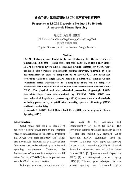
機械 機械手臂大氣電漿噴塗<br />
機械 臂大氣電漿噴塗 LSGM 電解質層性質研究<br />
電解質層性質研究<br />
Properties of LSGM Electrolyte Produced by Robotic<br />
Atmospheric Plasma Spraying<br />
羅志宏 黃振興 蔡俊煌<br />
Chih-Hung Lo, Chang-Sing Hwang, Chun-Huang Tsai<br />
核能研究所物理組<br />
Physics Division, Institute of Nuclear Energy Research<br />
Abstract<br />
LSGM electrolyte was found to be an electrolyte for the intermediate<br />
temperature (500-800℃) solid oxide fuel cells (SOFCs). In this paper, dense<br />
LSGM electrolyte layers with a thickness around 100μm for SOFC were<br />
produced using robotic atmospheric plasma spraying, followed by post<br />
heat-treatment at elevated temperatures of 600-900 ℃ . The as-sprayed<br />
electrolyte exhibits a single LSGM phase in a mixture of amorphous and<br />
crystalline states. Fortunately, the amorphous phase can be completely<br />
transferred into a crystalline phase at post heat-treatment temperature above<br />
700℃. The physical and electrochemical properties of gas-tight LSGM<br />
electrolyte have been characterized by FESEM, XRD, EDX and<br />
electrochemical impedance spectroscopy (EIS) measurements and analysis,<br />
including phase purity, crystallization, density, open circuit voltage (OCV)<br />
and ionic conductivity.<br />
Keywords: LSGM, Solid Oxide Fuel Cells (SOFCs), Atmospheric Plasma<br />
Spraying (APS)<br />
Solid oxide fuel cells is capable of<br />
generating electric power through the chemical<br />
reaction between gaseous fuel such as hydrogen<br />
and oxygen with high efficiency, and further<br />
their mechanical reliability can be improved and<br />
fabricating cost can be reduced by reducing cell<br />
operating temperature. Therefore, the<br />
development of intermediate temperature solid<br />
oxide fuel cell (IT-SOFC) is an important step<br />
towards SOFC commercialization.<br />
In the past years, several approaches have<br />
been made to the fabrication and<br />
characterization of LSGM for SOFC. The<br />
convention ceramic processes like slurry coating<br />
[1] and tape casting [2], chemical vapor<br />
deposition (CVD) techniques such as<br />
electrostatic assisted vapor deposition (EAVD)<br />
[3] and atomic layer epitaxy (ALE) [4], physical<br />
deposition processes such as pulsed laser<br />
ablation (PLA) [5, 6], electrophoretic deposition<br />
(EPD) [7] and atmospheric plasma spraying<br />
(APS) [8]. Thermal spray techniques, vacuum<br />
plasma spraying was considered highly
promising for producing thin and dense<br />
electrolyte layer such as yttria stabilized<br />
zirconia (YSZ) in most case. The study use<br />
inexpensive and universal APS system for<br />
integrated fabrication of dense electrolyte for a<br />
medium temperature button cell. Therefore, the<br />
technical issues associated with high density<br />
electrolyte deposition by APS, it is quite<br />
possible for fabricating high density electrolyte<br />
layer by APS if new electrolyte material is<br />
selected. For this reason, strontium- and<br />
magnesium-doped LaGaO3 perovskite oxide<br />
(LSGM) has been proposed as a possible<br />
electrolyte material for IT-SOFCs [9-12].<br />
The aim of this present paper is to<br />
evaluate the potential of the robotic atmospheric<br />
plasma spraying technique in producing thick<br />
films of LSGM. As well as to test and evaluate<br />
the physical and electrochemical properties of<br />
the button cell at temperatures for IT-SOFCs.<br />
2. Experimental apparatus<br />
The robotic APS system consists of<br />
mainly a DC plasma spray gun (Model SG-100,<br />
Praxair) that generates a high temperature<br />
plasma flame under atmospheric condition, a<br />
robotic (FANUC Robot ARC Mate 120iB) that<br />
holding plasma spray gun to scan substrate, a<br />
powder feeder for delivering plasma sprayable<br />
powders, a cooling system for the torch, a heater<br />
for preheating the substrate, an IR detector for<br />
measuring the temperature of the substrate and a<br />
fast CCD camera to observe trajectories of<br />
particles in the plasma flame. Figure 1<br />
schematically depicts the experimental set-up.<br />
The plasma sprayable La0.8Sr0.2Ga0.8<br />
Mg0.2O3 powders (LSGM, Inframat Inc.) are<br />
injected radially into the copper anode nozzle at<br />
the position 1.4 cm inward away from the<br />
nozzle's exit. These powders have an average<br />
size of 40-60 μm. These powders enter the<br />
plasma flame generated by a DC plasma torch,<br />
which heated and accelerated by the plasma<br />
flame to produce LSGM coatings on φ 24mm<br />
porous YSZ/Ni cermets anode. The operation<br />
parameters of atmospheric plasma spraying for<br />
LSGM are presented in Table 1.<br />
Figure 1 Schematic drawing of robotic<br />
atmospheric plasma spray system.<br />
Table 1 Atmospheric plasma spraying process<br />
parameter for deposition of LSGM.<br />
Parameter Value<br />
Power 28-40 kW<br />
Current 370-450 A<br />
High purity Argon gas flow rate 45-68 slpm<br />
Helium 15-38 slpm<br />
Hydrogen gas flow rate 3-12 slpm<br />
Powder feed rate 2-15 g/min<br />
Powder carry gas flow rate 2-8 slpm(Argon)<br />
Spray distance 6-10 cm<br />
Preheated substrate temperature<br />
450-850 ℃<br />
Shroud gas flow rate 35-60 slpm<br />
Robot scan speed 100-1000 mm/sec<br />
YSZ/Ni cermet and φ 24mm<br />
porous Ni<br />
substrates with a thickness of 2 mm. Substrates
are scanned by a robot to coat an area ofφ 24mm<br />
.<br />
The speed of the robot can be adjusted to as<br />
high as 2000 mm/sec. All coating experiments<br />
were conducted in the soundproof cabinet<br />
shown in Figure 1 to reduce the sound noise<br />
generated by the plasma torch. Table 1 presents<br />
typical operating parameters. FESEM, TEM,<br />
XRD, EDX and electrochemical impedance<br />
spectroscopy (EIS) equipment is adopted to<br />
analyze the coatings prepared in this study.<br />
3. Results and Discussion<br />
The LSGM electrolyte layer was plasma<br />
sprayed onto the YSZ/Ni anode layer. A novel<br />
YSZ/Ni anode coating with nanostructured<br />
features was produced [13].<br />
The X-ray diffraction patterns are shown<br />
in Figure 2, XRD analysis was handled for<br />
starting LSGM feedstock and as-spray<br />
deposition. The LSGM powder was identified<br />
by a single phase, nevertheless, the as-sprayed<br />
LSGM layer by amorphous phase characterized<br />
from the standard peaks. In order to investigate<br />
the transition temperature for the crystallization<br />
of the sprayed LSGM deposition, the deposition<br />
was exposed to post heat-treatment at various<br />
temperature from 600 to 900 ℃. XRD data<br />
indicate that LSGM deposition becomes to show<br />
low degree of crystallization after the heat<br />
treatment temperature exceeds 600 ℃, and a<br />
high degree of crystallization is identified above<br />
700 ℃ was shown in Figure 3,. From the point<br />
of oxygen ion conductivity, the formation of the<br />
amorphous phase in the LGSM layer is<br />
definitely negative. Fortunately, the XRD data<br />
confirmed that the chemical stoichiometry for<br />
the deposit is not altered, such as there is no<br />
decomposition occurring in the spray process,<br />
and full crystallization can be achieved in a post<br />
heat treatment at medium temperature.<br />
Lin (conuts)<br />
200<br />
150<br />
100<br />
50<br />
0<br />
300<br />
200<br />
100<br />
0<br />
20 30 40 50 60 70 80<br />
2-Theta (degree)<br />
LSGM APS layer<br />
LSGM feedstock<br />
Figure 2 X-ray diffraction patterns for LSGM<br />
feedstock powder and as-sprayed deposition<br />
Lin (counts)<br />
200<br />
100<br />
0<br />
200<br />
100<br />
0<br />
200<br />
100<br />
0<br />
100<br />
0<br />
100<br />
0<br />
Heat treatment at 900 oC, 1hr<br />
Heat treatment at 800 oC, 1hr<br />
Heat treatment at 700 oC, 1hr<br />
Heat treatment at 600 oC, 1hr<br />
LSGM APS layer<br />
without heat treatment<br />
20 30 40 50 60 70 80<br />
2-Theta (degree)<br />
Figure 3 X-ray diffraction patterns of the<br />
sprayed LSGM deposition after heat treatment<br />
in the air atmosphere at different temperature.<br />
Figure 4 was shows the FESEM image of<br />
the sprayed LSGM deposition cross section<br />
view. Generally viewing, the LSGM deposition<br />
layer is formed with a high density, uniform<br />
thickness and satisfactory interfacial connection<br />
with the porous YSZ-NiO anode. The main<br />
defect is isolated pores, probably attributing to
the inclusion of some un-melted large-size<br />
particles. Normally, the LSGM deposition layer<br />
is 100μm thick.<br />
Figure 4 FESEM cross section view of the<br />
sprayed LSGM deposition.<br />
Figure 5 shows Arrhenius plots of<br />
oxide-ion conductivity for the as-sprayed LSGM<br />
deposition layer at the measured temperature<br />
range of 600-800 ℃ . While the measured<br />
temperature at 600, 700 and 800 ℃ , the<br />
conductivity of the LSGM deposition layer is<br />
3.60 × 10 -3 , 4.69 × 10 -3 and 7.09 × 10 -3 Scm -1<br />
respectively. Furthermore, the activation energy<br />
was calculated to be 0.65 eV. It is dissimilar to<br />
the value of 0.998 eV with the report by Li et al.<br />
[14]. From the present, the density of the<br />
electrolyte and its phase’s impurity should be<br />
the main factors influencing on the activation<br />
energy of LSGM.<br />
The LSGM electrolyte layer has been<br />
deposit by atmospheric plasma spraying and its<br />
microstructure is shown in Figure 4. The<br />
electrolyte layer electrical performance was<br />
evaluated by open circuit voltage (OCV) at<br />
temperature 500-800℃. The result of OCV,<br />
0.96V at 760℃ and 0.982V at 700℃ is shown<br />
in Figure 6. Thus it can be seen, the OCV<br />
measured data has satisfactory gas tightness that<br />
atmospheric plasma spraying deposit LSGM<br />
electrolyte layer.<br />
log σ Τ (S cm -1 K)<br />
0.9<br />
0.8<br />
0.7<br />
0.6<br />
0.5<br />
0.4<br />
0.9 0.95 1 1.05 1.1 1.15<br />
T -1 10 3 (K -1 )<br />
Figure 5 Arrhenius plots of the LSGM<br />
electrolyte layer prepared by APS.<br />
E (Volts)<br />
1.2<br />
1.0<br />
0.8<br />
0.6<br />
0.4<br />
0.2<br />
0<br />
0 250 500 750 1000 1250 1500 1750 2000<br />
Time (Sec)<br />
Figure 6 Open circuit voltage of the LSGM<br />
electrolyte layer measured from 760 to 700℃.<br />
4. Conclusions<br />
760℃ 700℃<br />
The results presented in this study<br />
demonstrate that gas tight LSGM electrolyte<br />
layer can be successfully formed by the robotic<br />
APS system. The as-sprayed LSGM electrolyte<br />
layer contained an amorphous phase; however,<br />
crystallization LSGM could be achieved by heat<br />
treatment at temperature above 700 ℃ .<br />
Electrochemical impedance spectra indicated<br />
that the fully crystallized LSGM electrolyte has<br />
a high conductivity. With a good gas tightness
of the dense LSGM electrolyte, a half-cell open<br />
circuit voltage close to theoretical value was<br />
measured, which will operate at a medium<br />
temperature 500-800℃.<br />
Reference<br />
1. J.W. Yan, Z.G. Lu, Y. Jiang, Y.L. Dong, C.Y.<br />
Yu, W.Z. Li, “Fabrication and Testing of a<br />
Doped Lanthanum Gallate Electrolyte<br />
Thin-Film Solid Oxide Fuel Cell,” Journal of<br />
the Electrochemical Society, 149 [9]<br />
A1132-A1135 (2002).<br />
2. T. Fukui, S. Ohara, K. Murata, H. Yoshida, K.<br />
Miura, T. Inagaki, “Performance of<br />
intermediate temperature solid oxide fuel cells<br />
with La(Sr)Ga(Mg)O3 electrolyte film,”<br />
Journal of Power Sources, 106, 142-145<br />
(2002).<br />
3. K. Choy, W. Bai, S. Charojrochkul, B.C.H.<br />
Steele, “The development of<br />
intermediate-temperature solid oxide fuel cells<br />
for the next millennium,” Journal of Power<br />
Sources, 71, 361-369 (1998).<br />
4. N. Nieminen, S. Lehto, L. Niinistf, “Atomic<br />
layer epitaxy growth of LaGaO3 thin films,”<br />
Journal of Materials Chemistry, 11,<br />
3148-3153 (2001).<br />
5. T. Mathews, P. Manoravi, M.P. Antony, J.R.<br />
Sellar, B.C. Muddle, “Fabrication of<br />
La1−xSrxGa1−yMgyO3−(x+y)/2 thin films by<br />
pulsed laser ablation, Solid State Ionics,” 135,<br />
397-402 (2000).<br />
6. M. Joseph, P. Manoravi, H. Tabata, T. Kawai,<br />
“Preparation of La0.9Sr0.1Ga0.85Mg0.15O2.875<br />
thin films by pulsed-laser deposition and<br />
conductivity studies,” Journal of Applied<br />
Physics, 92, 997-1001 (2002).<br />
7. T. Mathews, N. Rabu, J.R. Sellar, B.C.<br />
Muddle, “Fabrication of<br />
La1−xSrxGa1−yMgyO3−(x+y)/2 thin films by<br />
electrophoretic deposition and its conductivity<br />
measurement,” Solid State Ionics, 128,<br />
111-115 (2000).<br />
8. X.Q. Ma, S. Hui, H. Zhang, J. Dai, J. Roth,<br />
T.D. Xiao, D.E. Reisner, “Intermediate<br />
Temperature SOFC Based on Fully Integrated<br />
Plasma Sprayed Components,” Journal of<br />
Thermal Spray Technology, 14, 61-66 (2005).<br />
9. T. Ishihara, H. Matsuda and Y. Takita,<br />
“Doped LaGaO3 perovskite type oxide as a<br />
new oxide ionic conductor,” J. Am.Chem.<br />
Soc., 116, 3801-3803 (1994).<br />
10. M. Feng, B. J. Goodenough, K. Huang, and<br />
C. Milliken, “Fuel cells with doped lanthanum<br />
gallate electrolyte,” J. Powder Sources, 63,<br />
47-51 (1996).<br />
11. K. Huang, M. Feng, J.B. Goodenough, and<br />
C. Mihken, “Electrode Performance Test on<br />
Single Ceramic Fuel Cells Using as<br />
Electrolyte Sr- and Mg-Doped LaGaO3,”<br />
Journal of the Electrochemical Society, 144,<br />
3460-3465 (1997).<br />
12. X. Zhang, S. Ohara, H. Okawa, R. Maric<br />
and T. Fukui, “Interactions of a<br />
La0.9Sr0.1Ga0.8Mg0.2O3-δelectrolyte with Fe2O3,<br />
Co2O3 and NiO anode materials,” Solid State<br />
Ionics, 139, 145-152 ( 2001).<br />
13. Changsing Hwang. Chia-Ho Yu, “Formation<br />
of nanostructured YSZ/Ni anode with pore<br />
channels by plasma spraying,” Surface &<br />
Coatings Technology, 201, 5954-5959 (2007).<br />
14. Zhi-Cheng Li, Hong Zhang, Bill Bergman,<br />
Xiaodong Zou, “Synthesis and<br />
characterization of La0.85Sr0.15Ga0.85Mg0.15O3- δ<br />
electrolyte by steric entrapment synthesis<br />
method,” Journal of the European Ceramic<br />
Society, 26, 2357-2364 (2006).