Create successful ePaper yourself
Turn your PDF publications into a flip-book with our unique Google optimized e-Paper software.
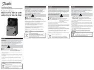
Data sheet<br />
Seated valves (PN 16)<br />
<strong>VF</strong> 2 – 2-way valve, flange<br />
<strong>VF</strong> 3 – 3-way valve, flange<br />
Description<br />
Ordering<br />
Example:<br />
2-way valve, DN 15, k VS 1.6, PN 16,<br />
t max 130 °C, flange connection<br />
- 1× <strong>VF</strong> 2 DN 15 valve<br />
Code No.: 065Z0273<br />
DEN-SMT/SI<br />
<strong>VF</strong> 2 and <strong>VF</strong> 3 valves provide a quality, cost<br />
effective solution for most water and chilled<br />
applications.<br />
The valves are designed to be <strong>com</strong>bined with<br />
following actuators:<br />
• DN 15-50 with AMV(E) 335, AMV(E) 435 or<br />
AMV(E) 438 SU actuators<br />
• DN 65-80 with AMV(E) 335 or AMV(E) 435<br />
actuators<br />
• DN 100 with AMV(E) 55, AMV(E) 56,<br />
AMV 423 or AMV 523 actuators<br />
• DN 125, 150 with AMV(E) 55, AMV(E) 56,<br />
AMV(E) 85 or AMV(E) 86 actuators.<br />
Combinations with other actuators could be<br />
seen under Accessories.<br />
2-way valve <strong>VF</strong> 2<br />
k VS<br />
VD.LS.D4.02 © <strong>Danfoss</strong> 05/2011<br />
<strong>VF</strong> 2 <strong>VF</strong> 3<br />
t max.<br />
DN<br />
(m<br />
Code No.<br />
3 /h) ( oC) 0.63<br />
065Z0271<br />
1.0 065Z0272<br />
15 1.6 065Z0273<br />
2.5 065Z0274<br />
4.0 065Z0275<br />
20 6.3 065Z0276<br />
25 10 130 065Z0277<br />
32 16 065Z0278<br />
40 25 065Z0279<br />
50 40 065Z0280<br />
65 63 065Z0281<br />
80 100 065Z0282<br />
100 145 065B3205<br />
125<br />
150<br />
220<br />
320<br />
200<br />
065B3230<br />
065B3255<br />
Features:<br />
• Bubble tight design<br />
• Snap mechanical connection together with<br />
AMV(E) 335, AMV(E) 435<br />
• Dedicated 2-port valve<br />
• Suitable for diverting applications (3-port)<br />
Main data:<br />
• DN 15-150<br />
• kVS 0.63-320 m 3 /h<br />
• PN 16<br />
• Temperature:<br />
- Circulation water/glycolic water up to 50 %:<br />
2 (–10*) … 130 °C (DN 15-100)<br />
2 (–10*) … 200 °C (DN 125, 150)<br />
* At temperatures from -10 °C up to +2 °C use stem heater<br />
• Flange PN 16 connections<br />
• Compliance with Pressure Equipment<br />
Directive 97/23/EC<br />
3-way valve <strong>VF</strong> 3<br />
k VS<br />
t max.<br />
DN<br />
(m<br />
Code No.<br />
3 /h) ( oC) 0.63<br />
065Z0251<br />
1.0 065Z0252<br />
15 1.6 065Z0253<br />
2.5 065Z0254<br />
4.0 065Z0255<br />
20 6.3 065Z0256<br />
25 10 130 065Z0257<br />
32 16 065Z0258<br />
40 25 065Z0259<br />
50 40 065Z0260<br />
65 63 065Z0261<br />
80 100 065Z0262<br />
100 145 065B1685<br />
125<br />
150<br />
220<br />
320<br />
200<br />
065B3125<br />
065B3150<br />
1
Data sheet Seated valves <strong>VF</strong> 2, <strong>VF</strong> 3<br />
Ordering (continued) Accessories - Adapter<br />
Technical data<br />
Nominal diameter DN 15 20 25 32 40 50 65 80 100 125 150<br />
kVS value m3 /h 0.63 1.0 1.6 2.5 4.0 6.3 10 16 25 40 63 100 145 220 320<br />
Stroke mm 10 15 20 30 40<br />
Control range 30:1 50:1 100:1<br />
Control characteristic LOG: port A-AB; LIN: port B-AB<br />
Cavitation factor z ≥ 0.4<br />
Leakage<br />
A - AB bubble tight design<br />
B - AB ≤ 1.0 % of kVS Nominal pressure PN 16<br />
Max. closing pressure<br />
(mixing)<br />
bar<br />
4 2.5<br />
Max. closing pressure<br />
(diverting)<br />
1 Not applicable<br />
Medium Circulation water/glycolic water up to 50 %<br />
Medium pH Min. 7, Max. 10<br />
Medium temperature oC 5) 2 (–10 ) … 130 5) 2 (–10 ) … 200<br />
Connections<br />
Materials<br />
Flange PN 16 acc. to EN 1092-2<br />
Valve body<br />
Grey cast iron<br />
EN-GJL-250 (GG-25)<br />
Valve stem Stainless steel<br />
2 VD.LS.D4.02 © <strong>Danfoss</strong> 05/2011 DEN-SMT/SI<br />
1.0 1)<br />
1.5 2)<br />
0.5 3)<br />
1.0 2)<br />
3.0 4)<br />
0.2 3)<br />
0.5 2)<br />
1.5 4)<br />
Ductile iron<br />
EN-GJS-400-18-LT<br />
(GGG 40.3)<br />
Valve cone Brass<br />
Red bronze<br />
CuSn5Zn5Pb5<br />
(Rg 5)<br />
GGG 40<br />
Stuffing box sealing EPDM PFTE<br />
1) for actuators AMV(E) 56, AMV 423, AMV 523<br />
2) for actuators AMV(E) 55<br />
3) for actuators AMV(E) 56<br />
4) for actuators AMV(E) 85, AMV(E) 86<br />
5) At temperatures from –10 up to +2 °C use stem heater<br />
DN Actuators max.∆p (bar) Code No.<br />
15-50 AMV(E) 15, 25, 35, 323, 423, 523 4.0 065Z0311<br />
65-80 AMV(E) 55, 56, 323, 423, 523 2.5 065Z0312<br />
Accessories - Stem heater<br />
DN Actuators Power supply Code No.<br />
15-80 AMV(E) 335, 435<br />
065Z0315<br />
15-50 AMV(E) 438 SU 065B2171<br />
65-100 AMV(E) 55, 56 24 V<br />
065Z7020<br />
125, 150 AMV(E) 55, 56 065Z7022<br />
125, 150 AMV(E) 85, 86 065Z7021<br />
Service kits<br />
Type DN Code No.<br />
15 065Z0321<br />
20 065Z0322<br />
25 065Z0323<br />
Stuffing box<br />
32<br />
40,50<br />
065Z0324<br />
065Z0325<br />
65,80 065Z0327<br />
100 065B1360<br />
125,150 065B0007
Data sheet Seated valves <strong>VF</strong> 2, <strong>VF</strong> 3<br />
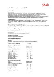
Pressure temperature<br />
diagram<br />
DEN-SMT/SI<br />
VD.LS.D4.02 © <strong>Danfoss</strong> 05/2011<br />
PN 16<br />
working area<br />
PN 16<br />
working area<br />
DN 15-100<br />
EN-GJL-250 (GG-25)<br />
DN 125, 150<br />
EN-GJS-400-18-LT (GGG 40.3)<br />
Maximum allowed operating pressure as a function of medium temperature (according to EN 1092-2)<br />
Valve characteristics Valve characteristics log (2-way) Valve characteristics log/lin (3-way)<br />
3
Data sheet Seated valves <strong>VF</strong> 2, <strong>VF</strong> 3<br />
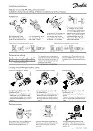
Installation Valve mounting<br />
Before valve mounting the pipes have to be<br />
cleaned and free from abrasion. Valve must<br />
be mounted according to flow direction as<br />
indicated on valve body. Mechanical loads of the<br />
valve body caused by the pipes are not allowed.<br />
Valve should be free of vibrations as well.<br />
Disposal<br />
Installation of the valve with the actuator is<br />
allowed in horizontal position or upwards.<br />
Installation downwards is not allowed.<br />
A AB<br />
B<br />
B<br />
Mixing Diverting<br />
Fig. 1: Mixing or diverting connection<br />
A AB<br />
Fig. 2: Mixing valve used in mixing application<br />
Mixing or diverting connection<br />
3-way valve can be used either as mixing or<br />
diverting valve (fig.1).<br />
If 3-way valve is installed as mixing valve<br />
meaning that A and B ports are inlet ports, and<br />
AB port is outlet port it can be installed in mixing<br />
(fig.2) or diverting application (fig.3).<br />
The valve must be dismantled and the elements<br />
sorted into various material groups before<br />
disposal.<br />
Fig. 3: Mixing valve used in diverting application<br />
Fig. 4: Diverting valve used in diverting application<br />
3-way valve can be also installed as diverting<br />
valve in diverting application (fig.4) meaning that<br />
AB port is inlet and A and B ports are outlets.<br />
Note:<br />
Only valves DN 15-50 are suitable for diverting<br />
installation. Maximal closing pressure for<br />
mixing and diverting installation are not the<br />
same. Please refer to values stated in Technical<br />
data section.<br />
4 VD.LS.D4.02 © <strong>Danfoss</strong> 05/2011 DEN-SMT/SI
Data sheet Seated valves <strong>VF</strong> 2, <strong>VF</strong> 3<br />
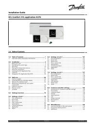
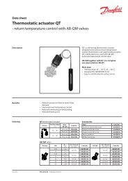
Sizing<br />
DEN-SMT/SI<br />
Example<br />
Design data:<br />
Flow rate: 6 m 3 /h<br />
System pressure drop: 55 kPa<br />
VD.LS.D4.02 © <strong>Danfoss</strong> 05/2011<br />
Flow Rate<br />
(liquid with specific a gravity of 1)<br />
l/sec m 3 /h<br />
Locate the horizontal line representing a flow<br />
rate of 6 m 3 /h (line A-A). The valve authority is<br />
given by the equation:<br />
∆p1<br />
Valve authority, a =<br />
∆p1+<br />
∆p2<br />
Where:<br />
Δp1 = pressure drop across the fully open<br />
valve<br />
Δp2 = pressure drop across the rest of the<br />
circuit with a full open valve<br />
The ideal valve would give a pressure drop equal<br />
to the system pressure drop (i.e. an authority of<br />
0.5):<br />
if: Δp1 = Δp2<br />
a = Δp1<br />
= 0.5<br />
2 × Δp1<br />
In this example an authority of 0.5 would be<br />
given by a valve having a pressure drop of<br />
55 kPa at that flow rate (point B). The intersection<br />
of line A–A with a vertical line drawn from B lies<br />
between two diagonal lines; this means that no<br />
ideally-sized valve is available.<br />
Δp max<br />
FLOW Pressure drop kPa (100 kPa = 1bar = ~ 10 m H 2 O)<br />
The intersection of line A–A with the diagonal<br />
lines gives the pressure drops stated by real,<br />
rather than ideal, valves. In this case, a valve with<br />
k VS 6.3 would give a pressure drop of 90.7 kPa<br />
(point C):<br />
90.<br />
7<br />
hence valve authority = = 0.<br />
62<br />
90.<br />
7 + 55<br />
The second largest valve, with k VS 10, would give<br />
a pressure drop of 36 kPa (point D):<br />
36<br />
hence valve authority = = 0.395<br />
36 + 55<br />
Generally, for a 3 port application, the smaller<br />
valve would be selected (resulting in a valve<br />
authority higher than 0.5 and therefore<br />
improved control). However, this will increase<br />
the total pressure and should be checked by the<br />
system designer for <strong>com</strong>patibility with available<br />
pump heads, etc. The ideal authority is 0.5 with a<br />
preferred range of between 0.4 and 0.7.<br />
5
Data sheet Seated valves <strong>VF</strong> 2, <strong>VF</strong> 3<br />
Design<br />
(Design variations are possible)<br />
<strong>VF</strong> 2<br />
1. Valve body<br />
2. Valve insert<br />
3. Valve cone<br />
4. Valve stem<br />
5. Moving valve seat<br />
(pressure relieved)<br />
6. Stuffing box<br />
<strong>VF</strong> 3<br />
1. Valve body<br />
2. Valve insert<br />
3. Valve cone<br />
4. Valve stem<br />
5. Valve seat<br />
6. Pressure relieve chamber<br />
7. Stuffing box<br />
6<br />
7<br />
6 VD.LS.D4.02 © <strong>Danfoss</strong> 05/2011 DEN-SMT/SI
Data sheet Seated valves <strong>VF</strong> 2, <strong>VF</strong> 3<br />
Dimensions<br />
<strong>VF</strong> 2 (DN 15-65) <strong>VF</strong> 2 (DN 80) AMV(E) 335, 435 + AMV(E) 438 SU +<br />
<strong>VF</strong> 2 (DN 15-80) <strong>VF</strong> 2 (DN 15-50)<br />
<strong>VF</strong> 3 (DN 15-65) <strong>VF</strong> 3 (DN 80) AMV(E) 335, 435 + AMV(E) 438 SU +<br />
<strong>VF</strong> 3 (DN 15-80) <strong>VF</strong> 3 (DN 15-50)<br />
Type DN<br />
L H H1<br />
mm<br />
H2 k d2<br />
n<br />
Weight<br />
(kg)<br />
15 130 47.5 191 216 65 14 4 1.93<br />
20 150 52.5 194 218 75 14 4 2.65<br />
25 160 57.5 197 222 85 14 4 3.23<br />
<strong>VF</strong> 2<br />
32<br />
40<br />
180<br />
200<br />
70<br />
75<br />
202<br />
213<br />
226<br />
237<br />
100<br />
110<br />
19<br />
19<br />
4<br />
4<br />
4.97<br />
6.59<br />
50 230 82.5 218 242 125 19 4 8.53<br />
65 290 92.5 254 279 145 19 4 15.92<br />
80 310 100 258 283 160 19 8 18.13<br />
15 130 63 191 216 65 14 4 2.61<br />
20 150 70 194 218 75 14 4 3.55<br />
25 160 75 197 222 85 14 4 4.54<br />
<strong>VF</strong> 3<br />
32<br />
40<br />
180<br />
200<br />
80<br />
90<br />
202<br />
230<br />
226<br />
255<br />
100<br />
110<br />
19<br />
19<br />
4<br />
4<br />
6.90<br />
9.05<br />
50 230 100 243 267 125 19 4 12.79<br />
65 290 120 254 279 145 19 4 19.18<br />
80 310 155 270 295 160 19 8 23.73<br />
Note:<br />
If stem heater is used dimension H is increased for 31 mm, dimension H2 is increased for 5 mm.<br />
7 VD.LS.D4.02 © <strong>Danfoss</strong> 05/2011 DEN-SMT/SI
Data sheet Seated valves <strong>VF</strong> 2, <strong>VF</strong> 3<br />
Dimensions (continued)<br />
DEN-SMT/SI<br />
VD.LS.D4.02 © <strong>Danfoss</strong> 05/2011<br />
<strong>VF</strong> 2 (DN 100) <strong>VF</strong> 3 (DN 100)<br />
AMV(E) 55, 56 + AMV 423, 523 +<br />
<strong>VF</strong> 2, <strong>VF</strong> 3 (DN 100) <strong>VF</strong> 2, <strong>VF</strong> 3 (DN 100)<br />
Type DN<br />
L H H1 H2<br />
mm<br />
k d2<br />
n<br />
Weight<br />
(kg)<br />
<strong>VF</strong> 2<br />
<strong>VF</strong> 3<br />
100 350<br />
196<br />
175<br />
406 317 170 18 4<br />
39.0<br />
34.0<br />
Note:<br />
If stem heater is used dimension H remains the same.<br />
8
Data sheet Seated valves <strong>VF</strong> 2, <strong>VF</strong> 3<br />
Dimensions (continued)<br />
<strong>VF</strong> 2 (DN 125, 150) <strong>VF</strong> 3 (DN 125, 150)<br />
AMV(E) 55, 56 + AMV(E) 85, 86 +<br />
<strong>VF</strong> 2, <strong>VF</strong> 3 (DN 125, 150) <strong>VF</strong> 2, <strong>VF</strong> 3 (DN 125, 150)<br />
Type DN<br />
L H H1 H2<br />
mm<br />
k d2<br />
n<br />
Weight<br />
(kg)<br />
<strong>VF</strong> 2<br />
125<br />
150<br />
400<br />
480<br />
160<br />
200<br />
629<br />
682<br />
555<br />
560<br />
210<br />
240<br />
18<br />
22<br />
8<br />
8<br />
54.0<br />
79.0<br />
<strong>VF</strong> 3<br />
125<br />
150<br />
400<br />
480<br />
250<br />
300<br />
629<br />
682<br />
555<br />
560<br />
210<br />
240<br />
18<br />
22<br />
8<br />
8<br />
65.3<br />
92.0<br />
Note:<br />
If stem heater is used dimensions H1 and H2 remain the same.<br />
9 VD.LS.D4.02 © <strong>Danfoss</strong> 05/2011 DEN-SMT/SI
Data sheet Seated valves <strong>VF</strong> 2, <strong>VF</strong> 3<br />
10 VD.LS.D4.02 © <strong>Danfoss</strong> 05/2011 DEN-SMT/SI
Data sheet Seated valves <strong>VF</strong> 2, <strong>VF</strong> 3<br />
11 VD.LS.D4.02 © <strong>Danfoss</strong> 05/2011 DEN-SMT/SI
Data sheet Seated valves <strong>VF</strong> 2, <strong>VF</strong> 3<br />
12 VD.LS.D4.02 Produced by <strong>Danfoss</strong> A/S © 05/2011