Installation Instructions Radiator thermostat RA 2000 ... - Danfoss.com
Installation Instructions Radiator thermostat RA 2000 ... - Danfoss.com
Installation Instructions Radiator thermostat RA 2000 ... - Danfoss.com

You also want an ePaper? Increase the reach of your titles
YUMPU automatically turns print PDFs into web optimized ePapers that Google loves.
<strong>Installation</strong> <strong>Instructions</strong><br />
<strong>Radiator</strong> <strong>thermostat</strong> <strong>RA</strong> <strong>2000</strong>, universal model<br />
<strong>Installation</strong>, temperature setting, limitation and blocking, theft protection<br />
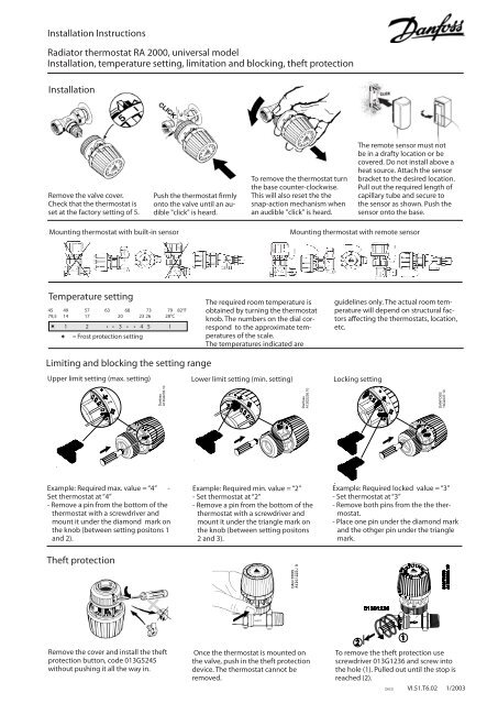
<strong>Installation</strong><br />
Remove the valve cover.<br />
Check that the <strong>thermostat</strong> is<br />
set at the factory setting of 5.<br />
Temperature setting<br />
45 49 57 63 68 73 79 82°F<br />
7 9,5 14 17 20 23 26 28°C<br />
l 1 2 • • 3 • • 4 5 l<br />
= Frost protection setting<br />
Limiting and blocking the setting range<br />
Upper limit setting (max. setting)<br />
Example: Required max. value = “4” -<br />
Set <strong>thermostat</strong> at “4”<br />
- Remove a pin from the bottom of the<br />
<strong>thermostat</strong> with a screwdriver and<br />
mount it under the diamond mark on<br />
the knob (between setting positons 1<br />
and 2).<br />
Theft protection<br />
Remove the cover and install the theft<br />
protection button, code 013G5245<br />
without pushing it all the way in.<br />
Push the <strong>thermostat</strong> firmly<br />
onto the valve until an audible<br />
"click" is heard.<br />
To remove the <strong>thermostat</strong> turn<br />
the base counter-clockwise.<br />
This will also reset the the<br />
snap-action mechanism when<br />
an audible "click" is heard.<br />
The required room temperature is<br />
obtained by turning the <strong>thermostat</strong><br />
knob. The numbers on the dial correspond<br />
to the approximate temperatures<br />
of the scale.<br />
The temperatures indicated are<br />
Lower limit setting (min. setting) Locking setting<br />
Example: Required min. value = “2”<br />
- Set <strong>thermostat</strong> at “2”<br />
- Remove a pin from the bottom of the<br />
<strong>thermostat</strong> with a screwdriver and<br />
mount it under the triangle mark on<br />
the knob (between setting positons<br />
2 and 3).<br />
Once the <strong>thermostat</strong> is mounted on<br />
the valve, push in the theft protection<br />
device. The <strong>thermostat</strong> cannot be<br />
removed.<br />
The remote sensor must not<br />
be in a drafty location or be<br />
covered. Do not install above a<br />
heat source. Attach the sensor<br />
bracket to the desired location.<br />
Pull out the required length of<br />
capillary tube and secure to<br />
the sensor as shown. Push the<br />
sensor onto the base.<br />
Mounting <strong>thermostat</strong> with built-in sensor Mounting <strong>thermostat</strong> with remote sensor<br />
guidelines only. The actual room temperature<br />
will depend on structural factors<br />
affecting the <strong>thermostat</strong>s, location,<br />
etc.<br />
Example: Required locked value = “3”<br />
- Set <strong>thermostat</strong> at “3”<br />
- Remove both pins from the the <strong>thermostat</strong>.<br />
- Place one pin under the diamond mark<br />
and the othger pin under the triangle<br />
mark.<br />
To remove the theft protection use<br />
screwdriver 013G1236 and screw into<br />
the hole (1). Pulled out until the stop is<br />
reached (2).<br />
DKCD VI.51.T6.02 1/2003
<strong>Installation</strong> <strong>Instructions</strong><br />
<strong>Radiator</strong> <strong>thermostat</strong> <strong>RA</strong> <strong>2000</strong>, tamper-proof model<br />
<strong>Installation</strong>, temperature setting, limiting and blocking, theft protection<br />
<strong>Installation</strong><br />
Remove the valve cover.<br />
Check that the <strong>thermostat</strong> is<br />
set at the factory setting of 5.<br />
Temperature setting<br />
45 49 57 63 68 73 79 82°F<br />
7 9,5 14 17 20 23 26 28°C<br />
l 1 2 • • 3 • • 4 5 l<br />
= Frost protection setting<br />
Example: Required max. value = “4” - Set<br />
<strong>thermostat</strong> at a setting below "4".<br />
- Remove a pin from the bottom of the<br />
<strong>thermostat</strong> with the threaded screwdriver<br />
and fit it at the position marked 4 on<br />
the back of the <strong>thermostat</strong> black cover.<br />
Theft protection<br />
Push the <strong>thermostat</strong> firmly<br />
onto the valve until an audible<br />
"click" is heard.<br />
Limiting and blocking the setting range<br />
Upper limit setting (max. setting)<br />
The clamping bland can be<br />
rotated to one of four positions<br />
to allow easier access<br />
to the allen screw.<br />
Loosen screw if required.<br />
The required room temperature is<br />
obtained by turning the <strong>thermostat</strong><br />
knob. The numbers on the dial correspond<br />
to the approximate temperatures<br />
of the scale.<br />
The temperatures indicated are<br />
Lower limit setting (min. setting) Locking setting<br />
Example: Required min. value = “2”<br />
- Set <strong>thermostat</strong> at a setting above "2".<br />
- Remove a pin from the bottom of the<br />
<strong>thermostat</strong> with the threaded screwdriver<br />
and fit it at the position marked<br />
2 on the back of the <strong>thermostat</strong> black<br />
cover.<br />
The remote sensor must not<br />
be in a drafty location or be<br />
covered. Do not install above a<br />
heat source. Attach the sensor<br />
bracket to the desired location.<br />
Pull out the required length of<br />
capillary tube and secure to<br />
the sensor as shown. Push the<br />
sensor onto the base.<br />
Mounting <strong>thermostat</strong> with built-in sensor Mounting <strong>thermostat</strong> with remote sensor<br />
Push the theft protection device into<br />
the hexagonal hole of the allen screw.<br />
The setting window can be covered using<br />
scale covers that are available as<br />
an accessory.<br />
guidelines only. The actual room temperature<br />
will depend on structural factors<br />
affecting the <strong>thermostat</strong>s, location,<br />
etc.<br />
Example: Required locked value = “3”<br />
- Set <strong>thermostat</strong> at a setting below "3".<br />
- Place one pin opposite the 3 on the<br />
back.<br />
- Turn the <strong>thermostat</strong> to setting "3".<br />
- Place the second pin opposite the 2<br />
on the back.<br />
Accessories<br />
Theft protection devices (20pcs) 013G1232<br />
Limit pins (10pcs) 013G1246<br />
Range limiting pins 013G1237<br />
<strong>Danfoss</strong> screwdriver set 013G1236<br />
Threaded screwdriver 013G1231<br />
Scale covers (20pcs) 013G1672<br />
DKCD VI.51.T6.02 1/2003