Thermostatic actuator QT - Danfoss.com
Thermostatic actuator QT - Danfoss.com
Thermostatic actuator QT - Danfoss.com

You also want an ePaper? Increase the reach of your titles
YUMPU automatically turns print PDFs into web optimized ePapers that Google loves.
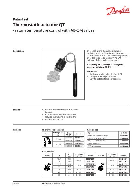
Data sheet<br />
<strong>Thermostatic</strong> <strong>actuator</strong> <strong>QT</strong><br />
- return temperature control with AB-QM valves<br />
Description<br />
Benefits • Reduces actual riser flow to match heat<br />
demand<br />
• Improved room temperature control<br />
• Reduced overheating of the building<br />
• Reduced heating cost<br />
Ordering<br />
DEN-SMT/SI<br />
<strong>QT</strong> thermostatic <strong>actuator</strong><br />
Picture<br />
AB-QM valves<br />
Setting range fit to<br />
(°C)<br />
AB-QM<br />
45 … 60<br />
35 … 50<br />
Picture DN<br />
Qmax.<br />
(l/h)<br />
10 LF 150<br />
VD.C6.U3.02 © <strong>Danfoss</strong> 03/2012<br />
Code No.<br />
DN 10-20 003Z0382<br />
DN 25-32 003Z0383<br />
DN 10-20 003Z0384<br />
DN 25-32 003Z0385<br />
Ext. thread<br />
(ISO 228/1)<br />
<strong>QT</strong> is a self-acting thermostatic <strong>actuator</strong><br />
designed to be used as return temperature<br />
control thermostat in one-pipe heating systems.<br />
<strong>QT</strong> is dedicated to be used with AB-QM<br />
automatic balancing & control valve.<br />
AB-QM together with <strong>QT</strong> is a <strong>com</strong>plete<br />
one-pipe solution: AB-<strong>QT</strong>.<br />
Main data:<br />
• Setting range: 35 … 50 °C, 45 … 60 °C<br />
• Designed for AB-QM DN 10-32<br />
• Easy-to-install external surface sensor<br />
Accessories<br />
Type Code No.<br />
Pocket for submersible sensor 003Z0391<br />
Adapter kit <strong>QT</strong> (DN 10-20) 003Z0392<br />
Adapter kit <strong>QT</strong> (DN 25-32) 003Z0393<br />
Sensor pocket kit 003Z0394<br />
<strong>QT</strong> flow setting tag 003Z0395<br />
Code No. AB-QM<br />
Ext. thread<br />
(ISO 228/1)<br />
Code No.<br />
003Z1261<br />
003Z1251<br />
G ½ A<br />
G ½ A<br />
10 275 003Z1211 003Z1201<br />
15 LF 275<br />
003Z1262<br />
003Z1252<br />
G ¾ A<br />
G ¾ A<br />
15 450 003Z1212 003Z1202<br />
20 900 G 1 A 003Z1213 G 1 A 003Z1203<br />
25 1,700 G 1¼ A 003Z1214 G 1¼ A 003Z1204<br />
32 3,200 G 1½ A 003Z1215 G 1½ A 003Z1205<br />
1
Data sheet <strong>Thermostatic</strong> <strong>actuator</strong> <strong>QT</strong><br />
Applications<br />
Fig. 1 Fig. 2 Fig. 3<br />
<strong>QT</strong> is designed to be used in <strong>com</strong>bination with<br />
AB-QM in one-pipe heating systems. AB-QM<br />
together with <strong>QT</strong> converts one-pipe heating<br />
system into energy efficient variable flow system,<br />
where flow in the risers is dynamically adjusted<br />
to match the load in the riser by control of return<br />
water temperature.<br />
In one-pipe systems flow in the riser is always<br />
present. TRV on the radiator controls room<br />
temperature by controlling flow through<br />
radiator. However, by reducing flow through the<br />
radiator, water flow is not reduced but diverted<br />
to a by-pass and thus total water flow in the riser<br />
remains permanent. Therefore at partial loads<br />
water temperature in the pipe is increasing.<br />
As a result the riser itself with the by-pass pipe<br />
continues to heat the room. This can cause<br />
overheating of the room.<br />
After the building is renovated the heating<br />
system be<strong>com</strong>es oversized since the heat losses<br />
of the building decrease. As a result overheating<br />
issue increases even more.<br />
AB-QM mounted in the riser provides a robust<br />
solution that offers reliable balance of one-pipe<br />
heating system at all system conditions. As a<br />
result, every riser gets design flow – and never<br />
more than that. Each riser be<strong>com</strong>es independent<br />
part of installation.<br />
In addition, <strong>QT</strong> as a self-acting return<br />
temperature thermostat installed on AB-QM<br />
provides flow control through the temperature<br />
of return water in the riser. By this water flow in<br />
the riser is dynamically controlled to match the<br />
actual load in the riser. This results in improved<br />
room temperature control and greatly reduced<br />
overheating of the building. Thus one-pipe<br />
systems be<strong>com</strong>e energy efficient variable flow<br />
systems, similar as Two-pipe systems are.<br />
Typical applications are:<br />
- one-pipe vertical riser based heating system<br />
(Fig. 1)<br />
- one-pipe horizontal loop based heating<br />
system (Fig. 2)<br />
- two-pipe vertical riser based heating system<br />
without TRV’s, such as staircase or bathroom<br />
risers (Fig. 3)<br />
2 VD.C6.U3.02 © <strong>Danfoss</strong> 03/2012 DEN-SMT/SI
Data sheet <strong>Thermostatic</strong> <strong>actuator</strong> <strong>QT</strong><br />
Technical data<br />
DEN-SMT/SI<br />
General data<br />
Setting range<br />
AB-QM<br />
50% setting<br />
Thermo paste<br />
VD.C6.U3.02 © <strong>Danfoss</strong> 03/2012<br />
<strong>QT</strong> setting 0 (min) <strong>QT</strong> setting 6 (max)<br />
P band P band<br />
Sensor holder<br />
Fastener<br />
Hot water supply<br />
35 … 50 45 … 60<br />
Temperature tolerance ±3<br />
°C<br />
P-band 1) 5 1) /8 2)<br />
Max adm temperature at sensor 90<br />
Capillary tube length m 0,6<br />
Materials<br />
Housing CuZn36Pb2As (CW 602N)<br />
Cone and diaphragm support MPPE (Noryl)<br />
Main spindle (CW 614N) Zn39Pb3<br />
Sensor cap Polypropylene (Borealis HF 700-SA)<br />
Temperature sensor Copper, mat. No. 2.0090<br />
Adapter<br />
Nut<br />
1) with AB-QM DN 10-20, at 50 % flow setting<br />
2) with AB-QM DN 25-32, at 50 % flow setting<br />
DN 10-20 CuZn39Pb3 (CW 614N), coated with Cu Zn8B<br />
DN 25-32 CuZn39Pb3 (CW 614N)<br />
DN 10-20 CuZn39Pb3 (CW 614N), coated with Cu Zn8B<br />
DN 25-32 CuZn39Pb3 (CW 614N)<br />
AB-QM<br />
50% setting<br />
<strong>QT</strong> setting 0 (min) <strong>QT</strong> setting 6 (max)<br />
P band P band<br />
Fig. 4 Functional graph for <strong>QT</strong> on AB-QM DN 10-20 Fig. 5 Functional graph for <strong>QT</strong> on AB-QM DN 25-32<br />
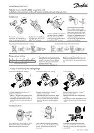
Mounting When used in vertical based one-pipe heating<br />
system (Fig.1) AB-QM is to be installed after the<br />
last radiator in the riser.<br />
In horizontal based heating system (Fig.2)<br />
AB-QM can be mounted also elsewhere in the<br />
loop, as long as the temperature sensor can be<br />
mounted after the last radiator in that loop.<br />
<strong>QT</strong> should be mounted on the AB-QM by hand.<br />
Maximum allowed torque is 5 Nm.<br />
It is re<strong>com</strong>mended to insulate the sensor if the<br />
thermostat is installed in a very cold place (< 5 °C).<br />
Fig. 6<br />
Installation of the sensor<br />
For proper heat transfer between a heating<br />
water pipe and the thermostat sensor, it is very<br />
important to apply thermo paste (included in the<br />
box) on the surfaces in contact.<br />
Sensor itself can be mounted in any direction.<br />
For best performance of <strong>QT</strong> it is re<strong>com</strong>mended<br />
to install sensor facing up (Fig. 7). It can be<br />
mounted either above or below sensor head.<br />
Fig. 7<br />
Best performance<br />
3
Data sheet <strong>Thermostatic</strong> <strong>actuator</strong> <strong>QT</strong><br />
Settings <strong>QT</strong> temperature setting depends on AB-QM flow<br />
setting.<br />
It is necessary to set the AB-QM according<br />
to required setting before the thermostat is<br />
mounted. It is re<strong>com</strong>mended to set AB-QM<br />
between 30 and 70 % flow setting.<br />
AB-QM DN 10-20 (45-60 °C)<br />
Temperature<br />
setting<br />
AB-QM (flow setting)<br />
<strong>QT</strong> Sensor setting (turns)<br />
0 1 2 3 4 5 6<br />
20 % 48,0 50,5 53,0 55,5 58,0 60,5 63,0<br />
30 % 47,0 49,5 52,0 54,5 57,0 59,5 62,0<br />
40 % 46,0 48,5 51,0 53,5 56,0 58,5 61,0<br />
50 % 45,0 47,5 50,0 52,5 55,0 57,5 60,0<br />
60 % 44,0 46,5 49,0 51,5 54,0 56,5 59,0<br />
70 % 43,0 45,5 48,0 50,5 53,0 55,5 58,0<br />
80 % 42,0 44,5 47,0 49,5 52,0 54,5 57,0<br />
90 % 41,0 43,5 46,0 48,5 51,0 53,5 56,0<br />
100 % 40,0 42,5 45,0 47,5 50,0 52,5 55,0<br />
AB-QM DN 10-20 (35-50 °C)<br />
Temperature<br />
setting<br />
AB-QM (flow setting)<br />
<strong>QT</strong> Sensor setting (turns)<br />
0 1 2 3 4 5 6<br />
20 % 38,0 40,5 43,0 45,5 48,0 50,5 53,0<br />
30 % 37,0 39,5 42,0 44,5 47,0 49,5 52,0<br />
40 % 36,0 38,5 41,0 43,5 46,0 48,5 51,0<br />
50 % 35,0 37,5 40,0 42,5 45,0 47,5 50,0<br />
60 % 34,0 36,5 39,0 41,5 44,0 46,5 49,0<br />
70 % 33,0 35,5 38,0 40,5 43,0 45,5 48,0<br />
80 % 32,0 34,5 37,0 39,5 42,0 44,5 47,0<br />
90 % 31,0 33,5 36,0 38,5 41,0 43,5 46,0<br />
100 % 30,0 32,5 35,0 37,5 40,0 42,5 45,0<br />
Factory setting is 4.<br />
<strong>QT</strong> thermostat is set to the desired setting by<br />
hand. When minimum or maximum setting<br />
is required, <strong>QT</strong> setting knob is to be moved<br />
slightly in opposite direction to ensure optimal<br />
performance of the thermostat.<br />
AB-QM DN 25-32 (45-60 °C)<br />
Temperature<br />
setting<br />
<strong>QT</strong> Sensor setting (turns)<br />
0 1 2 3 4 5 6<br />
4 VD.C6.U3.02 © <strong>Danfoss</strong> 03/2012 DEN-SMT/SI<br />
AB-QM (flow setting)<br />
20 % 49,5 52,0 54,5 57,0 59,5 62,0 64,5<br />
30 % 48,0 50,5 53,0 55,5 58,0 60,5 63,0<br />
40 % 46,5 49,0 51,5 54,0 56,5 59,0 61,5<br />
50 % 45,0 47,5 50,0 52,5 55,0 57,5 60,0<br />
60 % 43,5 46,0 48,5 51,0 53,5 56,0 58,5<br />
70 % 42,0 44,5 47,0 49,5 52,0 54,5 57,0<br />
80 % 40,5 43,0 45,5 48,0 50,5 53,0 55,5<br />
90 % 39,0 41,5 44,0 46,5 49,0 51,5 54,0<br />
100 % 37,5 40,0 42,5 45,0 47,5 50,0 52,5<br />
AB-QM DN 25-32 (35-50 °C)<br />
Temperature<br />
setting<br />
AB-QM (flow setting)<br />
<strong>QT</strong> Sensor setting (turns)<br />
0 1 2 3 4 5 6<br />
20 % 39,5 42,0 44,5 47,0 49,5 52,0 54,5<br />
30 % 38,0 40,5 43,0 45,5 48,0 50,5 53,0<br />
40 % 36,5 39,0 41,5 44,0 46,5 49,0 51,5<br />
50 % 35,0 37,5 40,0 42,5 45,0 47,5 50,0<br />
60 % 33,5 36,0 38,5 41,0 43,5 46,0 48,5<br />
70 % 32,0 34,5 37,0 39,5 42,0 44,5 47,0<br />
80 % 30,5 33,0 35,5 38,0 40,5 43,0 45,5<br />
90 % 29,0 31,5 34,0 36,5 39,0 41,5 44,0<br />
100 % 27,5 30,0 32,5 35,0 37,5 40,0 42,5
Data sheet <strong>Thermostatic</strong> <strong>actuator</strong> <strong>QT</strong><br />
Commissioning Flow on AB-QM and temperature setting on <strong>QT</strong><br />
need to be set to achieve best performance and<br />
efficiency of one-pipe heating system.<br />
DEN-SMT/SI<br />
Re<strong>com</strong>mended is a following 3 steps setting<br />
procedure:<br />
1. AB-QM setting<br />
2. <strong>QT</strong> setting<br />
3. follow up<br />
There are 2 main reasons that influence one-pipe<br />
system efficiency and therefore AB-QM and <strong>QT</strong><br />
setting:<br />
1. renovation status of the building since<br />
renovation is a major reason for a heating<br />
system to be<strong>com</strong>e oversized; generally, after<br />
building is renovated (wall & roof insulation,<br />
new windows) existing heating system<br />
be<strong>com</strong>es significantly oversized<br />
2. a dynamic nature of the heating load that is<br />
changing unpredictably in the building due<br />
to partial loads, internal gains and weather<br />
conditions.<br />
Note:<br />
After renovation, one of possible steps to improve<br />
efficiency of the one-pipe heating system is<br />
also optimization (reduction) of supply water<br />
temperature. Together with AB-<strong>QT</strong> if offers<br />
additional efficiency improvements where<br />
influences mostly upper radiators in the riser/loop.<br />
In such case <strong>QT</strong> setting would practically not need<br />
to change.<br />
VD.C6.U3.02 © <strong>Danfoss</strong> 03/2012<br />
1. AB-QM setting<br />
Required flow after building renovation is<br />
generally much lower than design flow that was<br />
calculated at the time building was designed.<br />
Flow is to be calculated based on actual heat<br />
losses–after renovation. Needed flow calculation<br />
is re<strong>com</strong>mended to be based on original Δt. For<br />
best performance, re<strong>com</strong>mended flow setting<br />
on AB-QM is between 30 and 70 % flow setting.<br />
2. <strong>QT</strong> setting – D f Dynamic factor method<br />
Temperature setting of the <strong>QT</strong> is influenced<br />
by dynamic factor D f. Last radiator in the riser<br />
is normally the one which influences dynamic<br />
factor D f at most. D f is to be selected from the<br />
table A. Having dynamic factor selected, the<br />
correction value of return temperature can be<br />
chosen from Fig. B.<br />
There are 2 factor that influence dynamic<br />
factor D f:<br />
1. ф r, Renovation effectiveness [%]<br />
2. Room type [A or B]<br />
D f can be selected for a building as a whole.<br />
However, various risers in the same building<br />
can have different characteristics (for example:<br />
kitchen <strong>com</strong>pared to sleeping room, riser in the<br />
middle of the building <strong>com</strong>pared to the one in<br />
the corner, etc). Therefore, for best efficiency<br />
also dynamic factor D f on various riser within the<br />
same building can be different.<br />
5
Data sheet <strong>Thermostatic</strong> <strong>actuator</strong> <strong>QT</strong><br />
Commissioning (continuous) 1 st factor, Renovation effectiveness ф r describes<br />
how much actual heat losses have been reduced<br />
after building renovation <strong>com</strong>pared to original,<br />
design value. ф r can be derived by:<br />
Qr<br />
r 100 1<br />
Q <br />
n<br />
<br />
<br />
<br />
<br />
<br />
<br />
Table A<br />
Df - Dynamic factor<br />
Having dynamic factor selected for a particular<br />
building/riser, the correction value of return<br />
temperature can be chosen from Fig. B.<br />
3. Follow up<br />
Achieved energy efficiency of AB-<strong>QT</strong> solution<br />
depends on <strong>QT</strong> setting. For maximum results it is<br />
strongly re<strong>com</strong>mended to perform follow up on<br />
the installation during first year of operation.<br />
Water T<br />
% <br />
[Q n ] - design heat losses (nominal)<br />
[Q r ] - actual heat losses (after renovation)<br />
<strong>QT</strong> setting<br />
Outside T<br />
A- potential<br />
energy savings<br />
area<br />
supply temperature<br />
design return temperature<br />
actual return temperature without <strong>QT</strong><br />
actual return temperature with <strong>QT</strong><br />
фr =renovation effectiveness [%]<br />
0 10 20 30 40 50 60<br />
Room type A (3 W/m 2 ) 8 19 31 43 54 66 78<br />
Room type B (9 W/m 2 ) 17 29 41 52 64 76 88<br />
Fig. 8a: <strong>QT</strong> Energy saving potential-higher <strong>QT</strong> setting<br />
2 nd factor depends on the what kind of room is<br />
heated by a particular riser. It is based on ISO<br />
13790:<br />
• Room typa A: bedroom room, utility, other<br />
rooms with low average internal gains of cca<br />
3 W/m 2<br />
• Room type B: kitchen or living room, with<br />
high average internal gains of cca 9 W/m 2<br />
Table A gives an overview of D f values, based on<br />
value of both factors respectively.<br />
<strong>QT</strong> setting is calculated so that “return temperature<br />
correction” value is <strong>com</strong>bined (summed up) with design<br />
return temperature (see examples).<br />
6 VD.C6.U3.02 © <strong>Danfoss</strong> 03/2012 DEN-SMT/SI<br />
Return temperature correction [°C]<br />
Water T<br />
Example 1<br />
Example 2<br />
More savings<br />
More conservative<br />
Dynamic factor [%]<br />
Fig. B - Return temperature correction<br />
For further details please contact <strong>Danfoss</strong><br />
representative or visit<br />
http://www.danfoss.<strong>com</strong>/onepipesolutions<br />
<strong>QT</strong> setting<br />
A- potential<br />
energy savings<br />
area<br />
Outside T<br />
supply temperature<br />
design return temperature<br />
actual return temperature without <strong>QT</strong><br />
actual return temperature with <strong>QT</strong><br />
Fig. 8b: <strong>QT</strong> Energy saving potential-lower <strong>QT</strong> setting
Data sheet <strong>Thermostatic</strong> <strong>actuator</strong> <strong>QT</strong><br />
Sizing – <strong>QT</strong> setting design<br />
examples<br />
DEN-SMT/SI<br />
1. Example<br />
Fig. 9 “Typical one-pipe riser with AB-QM & <strong>QT</strong><br />
installed”<br />
A well renovated building.<br />
Given:<br />
Design temperature system 90/70 °C<br />
Room type living room<br />
Design specific heat losses<br />
(before renovation) q n<br />
Specific heat losses<br />
(after renovation) q r<br />
Required<br />
Temperature setting for <strong>QT</strong><br />
VD.C6.U3.02 © <strong>Danfoss</strong> 03/2012<br />
33 W/m 2<br />
17 W/m 2<br />
Solution:<br />
Based on:<br />
• Room type B (for living room)<br />
• And ф r = 50 %, where renovation effectiveness<br />
ф r can be calculated as<br />
q r 17 <br />
r<br />
100<br />
1<br />
<br />
<br />
100<br />
1<br />
50%<br />
q <br />
n 33 <br />
dynamic factor D f 76 % can be identified from<br />
table A.<br />
2. Example<br />
A partly renovated building (for example<br />
windows renovated only)<br />
Given:<br />
Design temperature system 90/70 °C<br />
Room type bedroom<br />
Design specific heat losses qn (before renovation) 49 W/m2 Actual specific heat losses qr (after renovation) 37 W/m2 Actual riser heat losses Qr 10.950 W<br />
Required:<br />
1. AB-QM size & setting<br />
2. <strong>QT</strong> temperature setting<br />
3. <strong>QT</strong> sensor setting (turns)<br />
Solution<br />
1. AB-QM setting is calculated based on actual<br />
heat losses after renovation and design ΔT.<br />
Qr 10950<br />
q <br />
<br />
Cp<br />
t<br />
975<br />
4190<br />
20<br />
5<br />
q 1,<br />
34 10<br />
m<br />
3<br />
s 482l<br />
h<br />
3 m s<br />
AB-QM DN 20 is selected, where needed flow<br />
setting is 53 % for required 482 l/h.<br />
2. <strong>QT</strong> temperature setting<br />
Riser type 2 in table A is a proper match:<br />
• Room type A (bedroom)<br />
• And ф r = 25 %, where renovation<br />
effectiveness ф r can be calculated as<br />
Q n 37 <br />
r<br />
100<br />
1<br />
<br />
<br />
100<br />
1<br />
25%<br />
Q <br />
r 49 <br />
Fig. 9<br />
Based on D f = 76 %, Fig. B gives return<br />
temperature correction of –23 °C.<br />
Required <strong>QT</strong> setting is:<br />
47 °C (70 °C + (–23 °C) = 47 °C)<br />
Dynamic factor D f 37% can be indentified<br />
from table, based on ф r value of 25%<br />
(between 20 and 30%)<br />
Based on D f = 37%, Fig B gives return<br />
temperature correction of –13°C.<br />
Required <strong>QT</strong> setting is:<br />
57 °C (70 °C + (–13 °C) = 57 °C)<br />
3. <strong>QT</strong> sensor setting<br />
Required<br />
<strong>QT</strong> temperature setting<br />
AB-QM size DN 20<br />
AB-QM setting 53 %<br />
Solution<br />
On page 3, left setting table is selected<br />
that is valid for AB-QM DN10 –20 sizes. In a<br />
50% AB-QM setting row, required 57 °C <strong>QT</strong><br />
temperature setting corresponds to 5 turns.<br />
5 turns for <strong>QT</strong> sensor setting is selected.<br />
AB-QM DN 10-20 (45-60 °C)<br />
Temperature<br />
setting<br />
AB-QM (flow setting)<br />
<strong>QT</strong> Sensor setting (turns)<br />
0 1 2 3 4 5 6<br />
20 % 48,0 50,5 53,0 55,5 58,0 60,5 63,0<br />
30 % 47,0 49,5 52,0 54,5 57,0 59,5 62,0<br />
40 % 46,0 48,5 51,0 53,5 56,0 58,5 61,0<br />
50 % 45,0 47,5 50,0 52,5 55,0 57,5 60,0<br />
60 % 44,0 46,5 49,0 51,5 54,0 56,5 59,0<br />
70 % 43,0 45,5 48,0 50,5 53,0 55,5 58,0<br />
80 % 42,0 44,5 47,0 49,5 52,0 54,5 57,0<br />
90 % 41,0 43,5 46,0 48,5 51,0 53,5 56,0<br />
100 % 40,0 42,5 45,0 47,5 50,0 52,5 55,0<br />
7
Data sheet <strong>Thermostatic</strong> <strong>actuator</strong> <strong>QT</strong><br />
Design<br />
1. Setting knob<br />
2. Adapter<br />
3. AB-QM valve<br />
4. Hot-water pipe<br />
5. Temperature sensor<br />
6. Rubber selling for sensor<br />
7. Sensor holder<br />
Dimensions<br />
Learn more on www.danfoss.<strong>com</strong>/onepipesolutions<br />
L<br />
8 VD.C6.U3.02 Produced by <strong>Danfoss</strong> A/S © 03/2012<br />
L 1min<br />
H<br />
DN<br />
L L 1min H<br />
mm<br />
10 53 37 105<br />
15 65 31 113<br />
20 82 22 110<br />
25 104 19 125<br />
32 130 12 137