Bioremediation Field Evaluation Eielson Air Force Base, Alaska
Bioremediation Field Evaluation Eielson Air Force Base, Alaska
Bioremediation Field Evaluation Eielson Air Force Base, Alaska

Create successful ePaper yourself
Turn your PDF publications into a flip-book with our unique Google optimized e-Paper software.
four 50-ft square test plots in the<br />
contaminated area:<br />
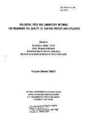
• A warm water test plot in<br />
which ground water collected<br />
via an extraction well was<br />
pumped through an electric<br />
heater, heated to about 35°C,<br />
then pumped through soaker<br />
hoses buried 2 ft underground<br />
at a rate of 1 gallon per minute<br />
(gpm). Water draining into a return<br />
manifold was returned to<br />
the extraction well for recirculation<br />
(see Figure 3). The heated<br />
water was applied below the<br />
ground surface to increase the<br />
temperature of the contaminated<br />
soil while minimizing<br />
volatilization of contaminants.<br />
Insulation was placed over the<br />
ground surface to retain heat.<br />
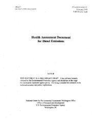
• A heat tape test plot in which<br />
strips of heat tape were buried<br />
at a depth of 3 ft to warm<br />
the soil directly (see Figure 4).<br />
The total heating rate was<br />
about 1 watt per square foot.<br />
Insulation was placed over the<br />
ground surface to retain heat.<br />
• A solar test plot in which insulation<br />
was placed over the ground<br />
surface during the winter months,<br />
then replaced with plastic mulch<br />
sheeting during the spring and<br />
summer months to capture solar<br />
heat and passively warm the soil.<br />
• A control test plot, which received<br />
no soil warming.<br />
All four test plots contained air injection/extraction<br />
wells, thermocouples<br />
for monitoring soil temperature, and<br />
three-level soil gas monitoring points<br />
for monitoring oxygen delivery and<br />
for sampling soil gas during in situ<br />
respiration tests (see Figures 5 and 6).<br />
Additional air injection/extraction<br />
wells, thermocouples, and soil gas<br />
monitoring points were installed at<br />
various points outside the test<br />
plots to permit monitoring across<br />
the contaminated site. The <strong>Air</strong><br />
<strong>Force</strong> and NRMRL monitored natural<br />
background respiration rates<br />
Figure 3. Circulation of heated ground water in the warm water test plot.<br />
Figure 4. Arrangement of heat tape strips in the heat tape test plot.<br />
in an uncontaminated area about<br />
200 ft east of the contaminated<br />
site. This area received air injection<br />
(via one injection/extraction well)<br />
but no soil warming; it also contained<br />
two soil gas monitoring<br />
points and one thermocouple.<br />
Ground-water contamination was<br />
monitored via ground-water monitoring<br />
wells installed at various<br />
points in contaminated and uncontaminated<br />
areas. These tests were<br />
conducted as part of the field<br />
evaluation, discussed below.<br />
With a couple of exceptions, the<br />
<strong>Air</strong> <strong>Force</strong> and NRMRL operated the<br />
6<br />
bioventing and soil warming systems<br />
for 3 years, from summer<br />
1991 to summer 1994. They terminated<br />
warm water circulation after<br />
2 years in order to compare microbial<br />
activity in the warm water test<br />
plot with and without active soil<br />
warming, and they operated the heat<br />
tape test plot for only 2 years (from<br />
summer 1992 to summer 1994).<br />
Conducting the<br />
<strong>Evaluation</strong><br />
The <strong>Air</strong> <strong>Force</strong> and NRMRL, with<br />
support from the <strong>Bioremediation</strong>