You also want an ePaper? Increase the reach of your titles
YUMPU automatically turns print PDFs into web optimized ePapers that Google loves.
19-4951; Rev 1; 11/09<br />
Step-Up, Step-Down Regulator, Gate-On Charge Pump,<br />
and Boost-Buck Regulator for TV TFT LCD Display<br />
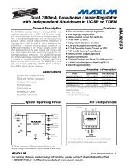
General Description<br />
The <strong>MAX17122</strong> multiple-output power-supply IC generates<br />
all the supply rails for thin-film transistor (TFT) liquidcrystal<br />
display (LCD) TV panels. It can operate from 8V<br />
to 16.5V input voltages and is optimized for LCD TV<br />
panel applications running directly from 12V regulated<br />
supplies. It includes a 22V internal-switch step-down<br />
regulator for digital logic, a 22V internal switch stepup<br />
regulator to power the TFT source drivers, and a<br />
temperature-compensated 36V internal-switch boostbuck<br />
regulator that produces a negative output that can<br />
vary according to the temperature sensed by an external<br />
NTC thermistor. All three of these regulators feature<br />
high-efficiency and fixed-frequency operation. Highfrequency<br />
operation allows the use of small inductors<br />
and capacitors, resulting in a compact solution.<br />
The <strong>MAX17122</strong> includes a positive charge-pump linear<br />
regulator controller that uses an external pnp bipolar<br />
junction transistor (BJT) to typically form a regulated<br />
charge-pump doubler to supply the LCD positive gatedriver<br />
supply voltage. A negative gate-driver supply is<br />
derived linearly between the boost-buck regulator’s output<br />
and ground, using an external npn BJT connected to<br />
ground and a small bypass capacitor.<br />
Other features include an external-capacitor-timed,<br />
open-drain, power-good output that monitors the stepdown<br />
regulator’s feedback and a simple untimed output<br />
that monitors the positive charge-pump linear regulator’s<br />
feedback. A high-voltage stress function is available for<br />
the step-up regulator output. The GATE output directly<br />
drives an external p-channel MOSFET to provide True<br />
ShutdownK of the step-up output.<br />
The <strong>MAX17122</strong> is available in a 6mm x 6mm, 40-pin thin<br />
QFN lead-free package and operates over the -40NC to<br />
+85NC temperature range.<br />
LCD TV Panels<br />
EVALUATION KIT<br />
AVAILABLE<br />
Applications<br />
True Shutdown and Dual Mode are trademarks of <strong>Maxim</strong><br />
Integrated Products, Inc.<br />
S 8V to 16.5V Operating Range<br />
S 750kHz Switching Frequency<br />
Ordering Information<br />
+Denotes a lead(Pb)-free/RoHS-compliant package.<br />
*EP = Exposed pad.<br />
Pin Configuration appears at end of data sheet.<br />
Features<br />
S 22V Internal-Switch High-Performance Step-Up<br />
Regulator<br />
Fast Load-Transient Response<br />
Current-Mode PWM Operation<br />
100mI, 3.9A nMOS Switch<br />
Capacitor-Adjustable Soft-Start<br />
High-Voltage Stress Function<br />
Drives External pMOS Shutdown Switch<br />
S 22V Internal-Switch Step-Down Regulator<br />
Preset 1% Accurate 3.3V Output Voltage or<br />
Adjustable Output (Dual Mode)<br />
Current-Mode PWM Operation<br />
200mI, 2.5A nMOS Switch<br />
Capacitor-Adjustable Power-Good Output<br />
S 36V Internal-Switch Boost-Buck Regulator<br />
Temperature-Compensated Output<br />
Programmable Fixed Levels with Temperature-<br />
Controlled Transition<br />
Current-Mode PWM Operation<br />
200mI, 1.8A pMOS Switch<br />
S Positive Charge-Pump Linear Regulator Controller<br />
Adjustable 1% Accurate Output Voltage<br />
Uses External pnp Transistor<br />
Regulates Switching-Node-Driven Charge-<br />
Pump Doubler<br />
Power-Good Output<br />
S Negative Linear Regulator Controller<br />
Adjustable 1.5% Accurate Output Voltage<br />
Uses External npn Transistor<br />
S Soft-Start for All Outputs<br />
S Adjustable Power-Up Sequence<br />
S Timed-Output Fault Protection with Restart for All<br />
Outputs<br />
S Latched Thermal-Shutdown Protection<br />
S 40-Pin, 6mm x 6mm Thin QFN Package<br />
PART TEMP RANGE PIN-PACKAGE<br />
<strong>MAX17122</strong>ETL+ -40NC to +85NC 40 TQFN-EP*<br />
_______________________________________________________________ <strong>Maxim</strong> Integrated Products 1<br />
For pricing, delivery, and ordering information, please contact <strong>Maxim</strong> Direct at 1-888-629-4642,<br />
or visit <strong>Maxim</strong>’s website at www.maxim-ic.com.<br />
<strong>MAX17122</strong>
<strong>MAX17122</strong><br />
Step-Up, Step-Down Regulator, Gate-On Charge Pump,<br />
and Boost-Buck Regulator for TV TFT LCD Display<br />
ABSOLUTE MAXIMUM RATINGS<br />
IN, IN2, IN3, EN1, EN2, LX1, GATE,<br />
DRVP, RHVS to AGND ......................................-0.3V to +22V<br />
GATE to IN ...........................................................-6.5V to +0.3V<br />
GND1 to AGND ................................................................. Q0.3V<br />
DLY1, DLY2, DEL, VL, RESET, GPGD,<br />
HVS to AGND ......................................................-0.3V to +6V<br />
FBP, FBN, FB1, FB2, FB3, COMP1, COMP3, OUTB<br />
SET, NTC, SS to AGND ......................... -0.3V to (VVL + 0.3V)<br />
DRVN to VL ...........................................................-36V to +0.3V<br />
LX2 to GND1 ............................................ -0.3V to (VIN2 + 0.3V)<br />
LX3 to IN3 ..............................................................-36V to +0.3V<br />
BST2 to VL .............................................................-0.3V to +22V<br />
BST2 to LX2 .............................................................-0.3V to +6V<br />
RMS LX1, GND1, IN2, IN3, LX3 Current (each pin) ............1.6A<br />
RMS LX2 (total for both pins) ...............................................2.4A<br />
RMS VL, DRVN, DRVP Current ..........................................50mA<br />
Continuous Power Dissipation (TA = +70NC)<br />
40-Pin Thin QFN<br />
(derate 35.7mW/NC above +70NC) .........................2857.1mW<br />
Operating Temperature Range .......................... -40NC to +85NC<br />
Junction Temperature .....................................................+160NC<br />
Storage Temperature Range ............................ -65NC to +165NC<br />
Lead Temperature (soldering, 10s) ................................+300NC<br />
Soldering Temperature (reflow) ......................................+260NC<br />
Stresses beyond those listed under “Absolute <strong>Maxim</strong>um Ratings” may cause permanent damage to the device. These are stress ratings only, and functional<br />
operation of the device at these or any other conditions beyond those indicated in the operational sections of the specifications is not implied. Exposure to absolute<br />
maximum rating conditions for extended periods may affect device reliability.<br />
ELECTRICAL CHARACTERISTICS<br />
(Circuit of Figure 1, VIN = VIN2 = VIN3 = 12V, TA = 0°C to +85°C. Typical values are at TA = +25NC, unless otherwise noted.)<br />
GENERAL<br />
PARAMETER CONDITIONS MIN TYP MAX UNITS<br />
IN, IN2, IN3<br />
Input-Voltage Range<br />
IN + IN2 + IN3<br />
Quiescent Current<br />
IN + IN2 + IN3<br />
Shutdown Current<br />
Only LX2 and LX3 switching (VFB1 = VFBP = 1.5V, VFB2 =<br />
1.1V, VFB3 = 1.8V, VFBN = 1.5V); VEN1 = VEN2 = 5V<br />
LX2 and LX3 not switching (VFB1 = VFB2 = VFBP = 1.5V,<br />
VFBN = 1.5V, VFB3 = 0); VEN1 = VEN2 = 5V<br />
2 ______________________________________________________________________________________<br />
8 16.5 V<br />
10 15<br />
2 4<br />
EN1 = EN2 = AGND (shutdown) 0.55 1 mA<br />
SMPS Operating Frequency 638 750 862 kHz<br />
Phase Difference Between<br />
Regulators<br />
IN Undervoltage-Lockout<br />
Threshold<br />
VL REGULATOR<br />
VL Output Voltage<br />
VL Undervoltage-Lockout<br />
Threshold<br />
STEP-DOWN REGULATOR<br />
Step-down and boost-buck 180<br />
Step-down and step-up 180<br />
mA<br />
Degrees<br />
VIN rising, 2.5% hysteresis 6 7 8 V<br />
IVL = 10mA, VFB1 = VFB2 = VFBP = 1.1V, VFBN = 0.75V,<br />
VFB3 = 1.8V (all regulators switching)<br />
OUTB Voltage in Fixed Mode FB2 = AGND, no load (Note 1)<br />
FB2 Voltage in Adjustable Mode VOUTB = 3.3V, no load (Note 1)<br />
FB2 Adjustable-Mode<br />
Threshold Voltage<br />
4.9 5.0 5.1 V<br />
VL rising, 2.5% hysteresis 3.6 4.0 4.4 V<br />
TA = +25NC 3.267 3.300 3.333<br />
0NC < TA < +85NC 3.25 3.35<br />
TA = +25NC 1.2375 1.250 1.2625<br />
0NC < TA < +85NC 1.23 1.27<br />
Dual-mode comparator 0.10 0.15 0.20 V<br />
V<br />
V
Step-Up, Step-Down Regulator, Gate-On Charge Pump,<br />
and Boost-Buck Regulator for TV TFT LCD Display<br />
ELECTRICAL CHARACTERISTICS (continued)<br />
(Circuit of Figure 1, VIN = VIN2 = VIN3 = 12V, TA = 0°C to +85°C. Typical values are at TA = +25NC, unless otherwise noted.)<br />
PARAMETER CONDITIONS MIN TYP MAX UNITS<br />
Output Voltage Adjust Range Step-down output 1.5 3.6 V<br />
FB2 Fault-Trip Level Falling edge 0.96 1.0 1.04 V<br />
FB2 Input-Bias Current VFB2 = 1.5V 50 125 200 nA<br />
DC Load Regulation 0.4A < ILOAD < 2A 0.5 %<br />
DC Line Regulation No load, 10.8V < VIN2 < 13.2V 0.1 %/V<br />
LX2-to-IN2 nMOS Switch<br />
On-Resistance<br />
LX2-to-GND1 nMOS Switch<br />
On-Resistance<br />
BST2-to-VL pMOS Switch<br />
On-Resistance<br />
Low-Frequency Operation<br />
OUTB Threshold<br />
Low-Frequency Operation<br />
Switching Frequency<br />
200 400 mI<br />
6 10 24 I<br />
6 12 24 I<br />
LX2 only 0.8 V<br />
188 kHz<br />
LX2 Positive Current Limit 2.5 3.0 3.5 A<br />
Soft-Start Ramp Time Zero to full limit 3 ms<br />
<strong>Maxim</strong>um Duty Factor 68 75 82 %<br />
BOOST-BUCK REGULATOR<br />
FB3 Regulation Voltage No load, VNTC = 2V<br />
TA = +25NC 1.63 1.65 1.67<br />
0NC < TA < +85NC 1.62 1.65 1.68<br />
FB3 Input-Bias Current VFB3 = 0.5V -50 -125 -210 nA<br />
FB3 Pulldown Resistance EN1 = AGND 300 1200 I<br />
FB3 Fault-Trip Level Rising edge 1.9 2.0 2.1 V<br />
DC Load Regulation 0A < ILOAD < 400mA 0.3 %<br />
DC Line Regulation No load, 10.8V < VIN2 < 13.2V 0.1 %/V<br />
LX3-to-IN3 pMOS Switch<br />
On-Resistance<br />
_______________________________________________________________________________________ 3<br />
V<br />
200 400 mI<br />
LX3 Positive Current Limit Duty cycle = 60% 1.8 2.1 2.4 A<br />
Soft-Start Ramp Time Zero to full limit 3 ms<br />
<strong>Maxim</strong>um Duty Factor 85 89 94 %<br />
NTC, SET Current<br />
NTC, SET Effective Voltage<br />
Range<br />
0NC < TA < +25NC 98 100 102<br />
+25NC < TA < +85NC 100<br />
0NC < TA < +25NC 0.1 1.65<br />
+25NC < TA < +85NC 0.3 1.65<br />
FA<br />
V<br />
<strong>MAX17122</strong>
<strong>MAX17122</strong><br />
Step-Up, Step-Down Regulator, Gate-On Charge Pump,<br />
and Boost-Buck Regulator for TV TFT LCD Display<br />
ELECTRICAL CHARACTERISTICS (continued)<br />
(Circuit of Figure 1, VIN = VIN2 = VIN3 = 12V, TA = 0°C to +85°C. Typical values are at TA = +25NC, unless otherwise noted.)<br />
PARAMETER CONDITIONS MIN TYP MAX UNITS<br />
STEP-UP REGULATOR<br />
Output-Voltage Range VIN 20 V<br />
Oscillator <strong>Maxim</strong>um Duty Cycle 70 76 83 %<br />
FB1 Regulation Voltage VFB1 = COMP, CCOMP = 1nF<br />
FB1 Output Undervoltage<br />
Fault Trip Level<br />
TA = +25NC 1.2375 1.250 1.2625<br />
0NC < TA < +85NC 1.23 1.27<br />
Falling edge 0.96 1.0 1.04 V<br />
FB1 Output Short Trip Level Falling edge 0.35 0.375 0.4 V<br />
FB1 Load Regulation 0 < ILOAD < full, transient only -1 %<br />
FB1 Line Regulation 10.8V < VIN < 13.2V 0.08 0.15 %/V<br />
FB1 Input-Bias Current VFB1 = 2V 10 125 200 nA<br />
FB1 Transconductance DI = Q2.5FA at COMP, FB1 = COMP 150 320 560 FS<br />
FB1 Voltage Gain FB1 to COMP 3500 V/V<br />
LX1 Bias Current VFB1 = 1.5V, VLX1 = 20V 10 40 FA<br />
LX1 Current Limit VFB1 = 1.1V, duty cycle = 25% 3.9 4.5 5.1 A<br />
Current-Sense Transresistance 0.16 0.23 0.3 V/A<br />
LX1 On-Resistance 100 200 mI<br />
SS Full Output Level 1.25 V<br />
SS Charge Current 6 9 12 FA<br />
POSITIVE CHARGE-PUMP LINEAR REGULATOR (DRVP)<br />
FBP Regulation Voltage IDRVP = 1.35mA<br />
TA = +25NC 1.2375 1.250 1.2625<br />
0NC < TA < +85NC 1.23 1.27<br />
FBP Input-Bias Current VFBP = 1.25V -50 +50 nA<br />
FBP Effective Load-Regulation<br />
Error (Transconductance)<br />
VDRVP = 15V, IDRVP = 0.6mA to 6mA 15 30 mV<br />
DRVP Sink Current VDRVP = 15V, VFBP = 1.1V 10 30 mA<br />
DRVP Off-Leakage Current VDRVP = 15V, VFBP = 1.5V 0.1 10 FA<br />
FBP Fault-Trip Level Falling edge 0.96 1.0 1.04 V<br />
Positive Regulator Soft-Start<br />
Period<br />
NEGATIVE LINEAR-REGULATOR CONTROLLER (DRVN)<br />
FBN Regulation Voltage IDRVN = 1.35mA<br />
7-bit voltage ramp with filtering to prevent high peak<br />
currents<br />
4 ______________________________________________________________________________________<br />
V<br />
V<br />
3 ms<br />
TA = +25NC 0.985 1 1.015<br />
0NC < TA < +85NC 0.98 1 1.02<br />
FBN Input-Bias Current -50 +50 nA<br />
FBN Pulldown Resistance EN1 = AGND 250 1000 I<br />
FBN Fault-Trip Level Falling edge 0.45 0.5 0.55 V<br />
FBN Effective Load-Regulation<br />
Error (Transconductance)<br />
VDRVN = -7.5V, IDRVN = 0.6mA to 6mA 23 46 mV<br />
DRVN Source Current VDRVN = -7.5V, VFBN = 0.85V 10 mA<br />
DRVN Off-Leakage Current VDRVN = -7.5V, VFBN = 1.15V 40 FA<br />
V
Step-Up, Step-Down Regulator, Gate-On Charge Pump,<br />
and Boost-Buck Regulator for TV TFT LCD Display<br />
ELECTRICAL CHARACTERISTICS (continued)<br />
(Circuit of Figure 1, VIN = VIN2 = VIN3 = 12V, TA = 0°C to +85°C. Typical values are at TA = +25NC, unless otherwise noted.)<br />
PARAMETER CONDITIONS MIN TYP MAX UNITS<br />
POWER-GOOD BLOCKS<br />
FB2 Power-Good Threshold FB2 rising 0.975 1.00 1.025 V<br />
FB2 Threshold Hysteresis 12 mV<br />
RESET Output Low Voltage IRESET = 1mA 0.4 V<br />
RESET Leakage Current VRESET = 3V 1 FA<br />
FBP Power-Good Threshold FBP rising 1.1 1.15 1.2 V<br />
FBP Threshold Hysteresis 125 mV<br />
GPGD Output Low Voltage IGPGD = 1mA 0.4 V<br />
GPGD Leakage Current VGPGD = 3V 1 FA<br />
GATE FUNCTION<br />
GATE Pulldown Current<br />
GATE charging current 0.15<br />
Gate done current 0.62<br />
GATE Drive Voltage VIN2 - VGATE, GATE enabled 5.0 5.35 5.65 V<br />
GATE Pullup Resistance GATE off, to IN2 25 I<br />
HVS BLOCK<br />
HVS Input Low Voltage 0.6 V<br />
HVS Input High Voltage 1.85 V<br />
HVS Input Pulldown Resistance 1 MI<br />
RHVS Output Resistance IRHVS = 4mA 25 I<br />
SEQUENCE CONTROL<br />
EN1, EN2, DLY1, DLY2, DEL<br />
Charge Current<br />
EN1, EN2, DLY1, DLY2, DEL<br />
Turn-On Threshold<br />
EN1, EN2 Discharge Switch<br />
On-Resistance<br />
DLY1, DLY2, DLP Discharge<br />
Switch On-Resistance<br />
FAULT DETECTION<br />
Measured at 1V 6 8.5 11 FA<br />
_______________________________________________________________________________________ 5<br />
mA<br />
1.25 1.30 V<br />
VL < UVLO or fault tripped 50 I<br />
EN1 = low or fault tripped 10 I<br />
Duration to Trigger Fault 50 ms<br />
Duration to Restart After Fault 160 ms<br />
Thermal-Shutdown Threshold Typical hysteresis = 15NC +160 NC<br />
<strong>MAX17122</strong>
<strong>MAX17122</strong><br />
Step-Up, Step-Down Regulator, Gate-On Charge Pump,<br />
and Boost-Buck Regulator for TV TFT LCD Display<br />
ELECTRICAL CHARACTERISTICS<br />
(Circuit of Figure 1, VIN = VIN2 = VIN3 = 12V, TA = -40°C to +85°C.) (Note 2)<br />
GENERAL<br />
PARAMETER CONDITIONS MIN TYP MAX UNITS<br />
IN, IN2, IN3<br />
Input-Voltage Range<br />
IN + IN2 + IN3<br />
Quiescent Current<br />
IN + IN2 + IN3<br />
Quiescent Current<br />
IN + IN2 + IN3<br />
Shutdown Current<br />
Only LX2 and LX3 switching (VFB1 = VFBP = 1.5V, VFB2 =<br />
1.1V, VFB3 = 1.8V, VFBN = 1.5V); VEN1 = VEN2 = 5V<br />
LX2 and LX3 not switching (VFB1 = VFB2 = VFBP = 1.5V,<br />
VFBN = 1.5V, VFB3 = 0); VEN1 = VEN2 = 5V<br />
6 ______________________________________________________________________________________<br />
8 16.5 V<br />
15 mA<br />
4 mA<br />
EN1 = EN2 = AGND (shutdown) 1 mA<br />
SMPS Operating Frequency 638 862 kHz<br />
IN Undervoltage-Lockout<br />
Threshold<br />
VL REGULATOR<br />
VL Output Voltage<br />
VL Undervoltage-Lockout<br />
Threshold<br />
STEP-DOWN REGULATOR<br />
VIN rising, 2.5% hysteresis 6 8 V<br />
IVL = 10mA, VFB1 = VFB2 = VFBP = 1.1V, VFBN = 0.75V,<br />
VFB3 = 1.8V (all regulators switching)<br />
4.9 5.1 V<br />
VL rising, 2.5% hysteresis 3.6 4.4 V<br />
OUTB Voltage in Fixed Mode FB2 = AGND, no load (Note 1) -40NC < TA < +85NC 3.25 3.35 V<br />
FB2 Voltage in Adjustable Mode VOUTB = 3.3V, no load (Note 1) -40NC < TA < +85NC 1.23 1.27 V<br />
FB2 Adjustable-Mode<br />
Threshold Voltage<br />
Dual-mode comparator 0.10 0.20 V<br />
Output Voltage Adjust Range Step-down output 1.5 3.6 V<br />
FB2 Fault-Trip Level Falling edge 0.96 1.04 V<br />
FB2 Input-Bias Current VFB2 = 1.5V 50 200 nA<br />
LX2-to-IN2 nMOS Switch<br />
On-Resistance<br />
LX2-to-GND1 nMOS Switch<br />
On-Resistance<br />
BST2-to-VL pMOS Switch<br />
On-Resistance<br />
400 mI<br />
6 24 I<br />
6 24 I<br />
LX2 Positive Current Limit 2.5 3.5 A<br />
<strong>Maxim</strong>um Duty Factor 68 82 %<br />
BUCK-BOOST REGULATOR<br />
FB3 Regulation Voltage No load, VNTC = 2V -40NC < TA < +85NC 1.62 1.68 V<br />
FB3 Input-Bias Current VFB3 = 0.5V -50 -210 nA<br />
FB3 Pulldown Resistance EN1 = AGND 300 1200 I<br />
FB3 Fault-Trip Level Rising edge 1.9 2.1 V<br />
LX3-to-IN3 pMOS Switch<br />
On-Resistance<br />
400 mI
Step-Up, Step-Down Regulator, Gate-On Charge Pump,<br />
and Boost-Buck Regulator for TV TFT LCD Display<br />
ELECTRICAL CHARACTERISTICS (continued)<br />
(Circuit of Figure 1, VIN = VIN2 = VIN3 = 12V, TA = -40°C to +85°C.) (Note 2)<br />
PARAMETER CONDITIONS MIN TYP MAX UNITS<br />
LX3 Positive Current Limit Duty cycle = 60% 1.8 2.4 A<br />
<strong>Maxim</strong>um Duty Factor 85 94 %<br />
NTC, SET Current -40NC < TA < +25NC 97 104 FA<br />
NTC, SET Effective Voltage<br />
Range<br />
STEP-UP REGULATOR<br />
0NC < TA < +25NC 0.1 1.65<br />
+25NC < TA < +85NC 0.3 1.65<br />
Output-Voltage Range VIN 20 V<br />
Oscillator <strong>Maxim</strong>um Duty Cycle 70 83 %<br />
FB1 Regulation Voltage FB1 = COMP, CCOMP = 1nF -40NC < TA < +85NC 1.23 1.27 V<br />
FB1 Output Undervoltage<br />
Fault-Trip Level<br />
Falling edge 0.96 1.04 V<br />
FB1 Output Short-Trip Level Falling edge 0.35 0.4 V<br />
FB1 Line Regulation 10.8V < VIN < 13.2V 0.15 %/V<br />
FB1 Input-Bias Current VFB1 = 2V 10 200 nA<br />
FB1 Transconductance DI = Q2.5FA at COMP, FB1 = COMP 150 560 FS<br />
LX1 Bias Current VFB1 = 1.5V, VLX1 = 20V 40 FA<br />
LX1 Current Limit VFB1 = 1.1V, duty cycle = 25% 3.9 5.1 A<br />
Current-Sense Transresistance 0.16 0.3 V/A<br />
LX1 On-Resistance 200 mI<br />
SS Charge Current 6 12 FA<br />
POSITIVE CHARGE-PUMP LINEAR REGULATOR (DRVP)<br />
FBP Regulation Voltage IDRVP = 1.35mA -40NC < TA < +85NC 1.23 1.27 V<br />
FBP Input-Bias Current VFBP = 1.25V -50 +50 nA<br />
FBP Effective Load-Regulation<br />
Error (Transconductance)<br />
VDRVP = 15V, IDRVP = 0.6mA to 6mA 30 mV<br />
DRVP Sink Current VDRVP = 15V, VFBP = 1.1V 10 30 mA<br />
DRVP Off-Leakage Current VDRVP = 15V, VFBP = 1.5V 10 FA<br />
FBP Fault-Trip Level Falling edge 0.96 1.04 V<br />
NEGATIVE LINEAR-REGULATOR CONTROLLER (DRVN)<br />
FBN Regulation Voltage IDRVN = 1.35mA -40NC < TA < +85NC 0.98 1.02 V<br />
FBN Input-Bias Current -50 +50 nA<br />
FBN Pulldown Resistance EN1 = AGND 250 1000 I<br />
FBN Fault-Trip Level Falling edge 0.45 0.55 V<br />
FBN Effective Load-Regulation<br />
Error (Transconductance)<br />
VDRVN = -7.5V, IDRVN = 0.6mA to 6mA 46 mV<br />
DRVN Source Current VDRVN = -7.5V, VFBN = 0.85V 10 mA<br />
DRVN Off-Leakage Current VDRVN = -7.5V, VFBN = 1.15V 40 FA<br />
_______________________________________________________________________________________ 7<br />
V<br />
<strong>MAX17122</strong>
<strong>MAX17122</strong><br />
Step-Up, Step-Down Regulator, Gate-On Charge Pump,<br />
and Boost-Buck Regulator for TV TFT LCD Display<br />
ELECTRICAL CHARACTERISTICS (continued)<br />
(Circuit of Figure 1, VIN = VIN2 = VIN3 = 12V, TA = -40°C to +85°C.) (Note 2)<br />
PARAMETER CONDITIONS MIN TYP MAX UNITS<br />
POWER-GOOD BLOCKS<br />
FB2 Power-Good Threshold FB2 rising 0.975 1.025 V<br />
RESET Output Low Voltage IRESET = 1mA 0.4 V<br />
RESET Leakage Current VRESET = 3V 1 FA<br />
FBP Power-Good Threshold FBP rising 1.1 1.2 V<br />
GPGD Output Low Voltage IGPGD = 1mA 0.4 V<br />
GPGD Leakage Current VGPGD = 3V 1 FA<br />
GATE FUNCTION<br />
GATE-Drive Voltage VIN2 - VGATE, GATE enabled 5.0 5.65 V<br />
HVS BLOCK<br />
HVS Input Low Voltage 0.6 V<br />
HVS Input High Voltage 1.85 V<br />
SEQUENCE CONTROL<br />
EN1, EN2, DLY1, DLY2, DEL<br />
Charge Current<br />
EN1, EN2, DLY1, DLY2, DEL<br />
Turn-On Threshold<br />
Measured at 1V 6 11 FA<br />
Note 1: When the inductor is in continuous conduction (EN2 = VL or heavy load), the output voltage has a DC regulation level<br />
lower than the error-comparator threshold by 50% of the output-voltage ripple. In discontinuous conduction (light load),<br />
the step-down regulator’s output voltage has a DC regulation level higher than the error-comparator threshold by up to<br />
50% of the output-voltage ripple.<br />
Note 2: Specifications to -40NC are guaranteed by design, not production tested.<br />
8 ______________________________________________________________________________________<br />
1.30 V
Step-Up, Step-Down Regulator, Gate-On Charge Pump,<br />
and Boost-Buck Regulator for TV TFT LCD Display<br />
(TA = +25°C, unless otherwise noted.)<br />
EFFICIENCY (%)<br />
OUTPUT-VOLTAGE ERROR (%)<br />
90<br />
85<br />
80<br />
75<br />
70<br />
65<br />
STEP-DOWN REGULATOR EFFICIENCY<br />
vs. LOAD CURRENT<br />
VIN = 10V<br />
VIN = 12V<br />
60<br />
0.10 1<br />
10<br />
0A<br />
0V<br />
LOAD CURRENT (A)<br />
STEP-DOWN REGULATOR LOAD-TRANSIENT<br />
RESPONSE (0.2A TO 1.7A)<br />
<strong>MAX17122</strong> toc03<br />
0A<br />
L = 4.7µH<br />
0.10<br />
0.05<br />
0<br />
-0.05<br />
-0.10<br />
-0.15<br />
-0.20<br />
-0.25<br />
-0.30<br />
20µs/div<br />
STEP-UP REGULATOR NORMALIZED<br />
OUTPUT VOLTAGE vs. LOAD CURRENT<br />
VIN = 12V<br />
VIN = 10V<br />
-0.35<br />
0 0.5 1.0 1.5 2.0 2.5<br />
LOAD CURRENT (A)<br />
<strong>MAX17122</strong> toc01<br />
<strong>MAX17122</strong> toc05<br />
IL2<br />
1A/div<br />
VOUTB<br />
(AC-COUPLED)<br />
200mV/div<br />
ILOAD<br />
1A/div<br />
Typical Operating Characteristics<br />
OUTPUT-VOLTAGE ERROR (%)<br />
EFFICIENCY (%)<br />
STEP-DOWN REGULATOR NORMALIZED<br />
OUTPUT VOLTAGE vs. LOAD CURRENT<br />
LOAD CURRENT (A)<br />
_______________________________________________________________________________________ 9<br />
0.6<br />
0.4<br />
0.2<br />
0<br />
-0.2<br />
-0.4<br />
-0.6<br />
-0.8<br />
-1.0<br />
-1.2<br />
VIN = 12V<br />
VIN = 10V<br />
-1.4<br />
0 0.4 0.8 1.2 1.6 2.0 2.4<br />
96<br />
94<br />
92<br />
90<br />
88<br />
86<br />
84<br />
82<br />
STEP-UP REGULATOR EFFICIENCY<br />
vs. LOAD CURRENT<br />
VIN = 12V<br />
VIN = 10V<br />
80<br />
0.01 0.10<br />
1<br />
10<br />
0A<br />
0V<br />
0A<br />
LOAD CURRENT (A)<br />
STEP-UP REGULATOR LOAD-TRANSIENT<br />
RESPONSE (0.2A TO 1.2A)<br />
<strong>MAX17122</strong> toc06<br />
L1 = 4.7µH<br />
CCOMP1 = 330pF<br />
RCOMP1 = 39.2kI<br />
CCOMP1P = 10pF<br />
40µs/div<br />
<strong>MAX17122</strong> toc02<br />
<strong>MAX17122</strong> toc04<br />
IL1<br />
1A/div<br />
VAVDD<br />
(AC-COUPLED)<br />
200mV/div<br />
ILOAD<br />
1A/div<br />
<strong>MAX17122</strong>
<strong>MAX17122</strong><br />
Step-Up, Step-Down Regulator, Gate-On Charge Pump,<br />
and Boost-Buck Regulator for TV TFT LCD Display<br />
(TA = +25°C, unless otherwise noted.)<br />
PEAK INDUCTOR CURRENT (A)<br />
6.0<br />
5.8<br />
5.6<br />
5.4<br />
5.2<br />
5.0<br />
4.8<br />
4.6<br />
4.4<br />
4.2<br />
0A<br />
0V<br />
0A<br />
L1 = 4.7µH<br />
CCOMP1 = 330pF<br />
RCOMP1 = 39.2kI<br />
CCOMP1P = 10pF<br />
STEP-UP REGULATOR PULSED<br />
LOAD-TRANSIENT<br />
RESPONSE (0.2A TO 2.2A)<br />
<strong>MAX17122</strong> toc07<br />
10µs/div<br />
STEP-UP REGULATOR PEAK<br />
INDUCTOR CURRENT AT CURRENT<br />
LIMIT vs. INPUT VOLTAGE<br />
4.0<br />
8 9 10 11 12 13<br />
INPUT VOLTAGE (V)<br />
<strong>MAX17122</strong> toc09<br />
EFFICIENCY (%)<br />
Typical Operating Characteristics (continued)<br />
90<br />
85<br />
80<br />
75<br />
70<br />
65<br />
60<br />
55<br />
IL1<br />
1A/div<br />
VAVDD<br />
(AC-COUPLED)<br />
200mV/div<br />
ILOAD<br />
1A/div<br />
STEP-UP REGULATOR<br />
STARTUP SEQUENCE <strong>MAX17122</strong> toc08<br />
10 _____________________________________________________________________________________<br />
0V<br />
0V<br />
0V<br />
0V<br />
BOOST-BUCK REGULATOR<br />
EFFICIENCY vs. LOAD CURRENT<br />
VIN = 10V<br />
VIN = 12V<br />
50<br />
0.01 0.10<br />
1<br />
LOAD CURRENT (A)<br />
<strong>MAX17122</strong> toc10<br />
4ms/div<br />
OUTPUT-VOLTAGE ERROR (%)<br />
0.50<br />
0<br />
-0.50<br />
-1.00<br />
-1.50<br />
VEN2<br />
5V/div<br />
VGATE<br />
10V/div<br />
VAVDD<br />
10V/div<br />
VLX1<br />
10V/div<br />
BOOST-BUCK REGULATOR NORMALIZED<br />
OUTPUT VOLTAGE vs. LOAD CURRENT<br />
VIN = 10V<br />
-2.00<br />
0 0.1 0.2 0.3 0.4 0.5 0.6 0.7 0.8<br />
LOAD CURRENT (A)<br />
VIN = 12V<br />
<strong>MAX17122</strong> toc11
Step-Up, Step-Down Regulator, Gate-On Charge Pump,<br />
and Boost-Buck Regulator for TV TFT LCD Display<br />
(TA = +25°C, unless otherwise noted.)<br />
OUTPUT VOLTAGE (V)<br />
0<br />
-5<br />
-10<br />
-15<br />
-20<br />
0V<br />
0A<br />
L3 = 22µH<br />
CCOMP3 = 470pF<br />
RCOMP3 = 47.5kI<br />
CCOMP3P = 10pF<br />
BOOST-BUCK REGULATOR<br />
LOAD-TRANSIENT<br />
RESPONSE (40mA TO 380mA)<br />
<strong>MAX17122</strong> toc12<br />
BOOST-BUCK REGULATOR OUTPUT<br />
TEMPERATURE COMPENSATION<br />
-25<br />
-40 -20 0 20 40 60 80<br />
TEMPERATURE (°C)<br />
100µs/div<br />
<strong>MAX17122</strong> toc14<br />
OUTPUT-VOLTAGE ERROR (%)<br />
Typical Operating Characteristics (continued)<br />
0.2<br />
0<br />
-0.2<br />
-0.4<br />
-0.6<br />
-0.8<br />
VGOFF2<br />
(AC-COUPLED)<br />
200mV/div<br />
ILOAD<br />
200mA/div<br />
PEAK INDUCTOR CURRENT (A)<br />
BOOST-BUCK REGULATOR PEAK<br />
INDUCTOR CURRENT AT CURRENT<br />
LIMIT vs. INPUT VOLTAGE<br />
POSITIVE CHARGE-PUMP<br />
REGULATOR LOAD-TRANSIENT<br />
RESPONSE (0A TO 100mA)<br />
<strong>MAX17122</strong> toc16<br />
VGON<br />
(AC-COUPLED)<br />
1V/div<br />
ILOAD<br />
50mA/div<br />
______________________________________________________________________________________ 11<br />
2.40<br />
2.35<br />
2.30<br />
2.25<br />
2.20<br />
2.15<br />
2.10<br />
2.05<br />
POSITIVE CHARGE-PUMP REGULATOR<br />
NORMALIZED LOAD REGULATION<br />
VIN = 12V<br />
VAVDD = 16.5V<br />
IAVDD = 350mA<br />
LOAD CURRENT (mA)<br />
2.00<br />
8 9 10 11 12 13 14<br />
VIN = 10V<br />
-1.0<br />
0 50 100 150 200<br />
<strong>MAX17122</strong> toc15<br />
0V<br />
0A<br />
INPUT VOLTAGE (V)<br />
VAVDD = 16.5V<br />
IAVDD = 350mA<br />
40µs/div<br />
<strong>MAX17122</strong> toc13<br />
<strong>MAX17122</strong>
<strong>MAX17122</strong><br />
Step-Up, Step-Down Regulator, Gate-On Charge Pump,<br />
and Boost-Buck Regulator for TV TFT LCD Display<br />
(TA = +25°C, unless otherwise noted.)<br />
OUTPUT-VOLTAGE ERROR (%)<br />
0.5<br />
0.4<br />
0.3<br />
0.2<br />
0.1<br />
0<br />
-0.1<br />
-0.2<br />
-0.3<br />
-0.4<br />
0V<br />
0V<br />
0V<br />
0V<br />
0V, 0V<br />
0V<br />
0V<br />
NEGATIVE LINEAR REGULATOR<br />
NORMALIZED LOAD REGULATION<br />
-0.5<br />
0 100 200 300 400 500<br />
VIN = 10V/div<br />
VEN1 = 5V/div<br />
VOUTB = 5V/div<br />
VEN2 = 5V/div<br />
LOAD CURRENT (mA)<br />
POWER-UP SEQUENCE OF<br />
ALL SUPPLY OUTPUTS <strong>MAX17122</strong> toc19<br />
10ms/div<br />
VGON = 10V/div<br />
VAVDD = 10V/div<br />
VGOFF1 = 5V/div<br />
VGOFF2 = 10V/div<br />
Typical Operating Characteristics (continued)<br />
<strong>MAX17122</strong> toc17<br />
VIN<br />
VEN1<br />
VOUTB<br />
VEN2<br />
VGON<br />
VAVDD<br />
VGOFF1<br />
VGOFF2<br />
NEGATIVE LINEAR REGULATOR<br />
LOAD-TRANSIENT<br />
RESPONSE (0A TO 100mA)<br />
<strong>MAX17122</strong> toc18<br />
12 _____________________________________________________________________________________<br />
0V<br />
0A<br />
0V<br />
0V<br />
0V<br />
20µs/div<br />
RESET FUNCTION <strong>MAX17122</strong> toc20<br />
4ms/div<br />
VGOFF1<br />
(AC-COUPLED)<br />
100mV/div<br />
ILOAD<br />
50mA/div<br />
VOUTB<br />
2V/div<br />
VDEL<br />
1V/div<br />
VRESET<br />
2V/div
Step-Up, Step-Down Regulator, Gate-On Charge Pump,<br />
and Boost-Buck Regulator for TV TFT LCD Display<br />
PIN NAME FUNCTION<br />
1 GATE<br />
2 IN<br />
3, 4 IN2<br />
5, 24 AGND Analog Ground<br />
6, 7 LX2<br />
8 BST2<br />
9 OUTB<br />
10 FB2<br />
11 GPGD<br />
12 DLY1<br />
13 EN1<br />
14 EN2<br />
15 HVS<br />
16 FBN<br />
Pin Description<br />
External p-Channel MOSFET Control Output. When the step-up regulator is enabled, GATE<br />
pulls down to control the step-up output during its soft-start. Once GATE is fully on, the step-up<br />
regulator begins switching to regulate the final portion of its soft-start.<br />
Input of the Internal 5V Linear Regulator and the Startup Circuitry. Bypass IN to AGND with 0.22FF<br />
close to the IC.<br />
Step-Down Regulator Power Input. Drain of the internal n-channel MOSFET connected between<br />
IN2 and LX2.<br />
Step-Down Regulator Switching Node. LX2 is the source of the internal n-channel MOSFET<br />
connected between IN2 and LX2. Connect the inductor and Schottky catch diode to LX2 and minimize<br />
the trace area for low EMI.<br />
Step-Down Regulator Bootstrap Capacitor Connection for High-Side Gate Driver. Connect a 0.1FF<br />
ceramic capacitor from BST2 to LX2.<br />
Step-Down Regulator Output-Voltage Sense Input. Connect OUTB to the step-down regulator<br />
output.<br />
Step-Down Regulator Feedback Input. Connect FB2 to AGND to select the step-down converter’s<br />
3.3V fixed mode. For adjustable mode, connect FB2 to the center of a resistive voltage-divider<br />
between the step-down regulator output and AGND to set the step-down regulator output voltage.<br />
Place the resistive voltage-divider within 5mm of FB2.<br />
GON Power-Good Signal Open-Drain Output. GPGD is connected to AGND whenever VFBP is less<br />
than the VFBP power-good threshold. GPGD is high impedance whenever VFBP is greater than the<br />
threshold.<br />
Step-Up Regulator Delay Input. Connect a capacitor from DLY1 and AGND to set the delay time<br />
between EN2’s rise and the step-up regulator’s soft-start. An 8FA current source charges CDLY1.<br />
DLY1 is internally pulled to AGND whenever either EN1 or EN2 is low or VL is below its UVLO<br />
threshold.<br />
Step-Down Enable Input. An 8FA current source charges the capacitor at EN1. When EN1 is high,<br />
the step-down regulator begins operating.<br />
Step-Up and Positive Charge-Pump Linear Regulator Enable Input. Negative linear regulator and<br />
boost-buck regulator enable input. An 8FA current source charges the capacitor at EN2. When<br />
EN2 is high, DLY1 and DLY2 begin charging. DLY1 starts GATE, which turns on the external<br />
p-channel MOSFET and the step-up regulator. DLY2 starts the positive charge-pump linear regulator.<br />
EN2 is inactive until after the step-down regulator soft-start is finished.<br />
High-Voltage Stress Mode Control Input. When HVS is high, the RHVS open-drain output connects<br />
to AGND. RHVS is high impedance when HVS is low.<br />
Negative Linear-Regulator Controller Feedback Input. Connect FBN to the center of a resistive<br />
voltage-divider between the negative output and a 3.3V reference to set the negative chargepump<br />
regulator output voltage. Place the resistive voltage-divider within 5mm of FBN.<br />
______________________________________________________________________________________ 13<br />
<strong>MAX17122</strong>
<strong>MAX17122</strong><br />
Step-Up, Step-Down Regulator, Gate-On Charge Pump,<br />
and Boost-Buck Regulator for TV TFT LCD Display<br />
PIN NAME FUNCTION<br />
17 SS<br />
18 DRVN<br />
19 DLY2<br />
20 FBP<br />
21 DRVP<br />
22 RESET<br />
23 DEL<br />
25 SET<br />
26 NTC<br />
27 FB3<br />
28 COMP3<br />
Pin Description (continued)<br />
Step-Up Regulator Soft-Start Input. Connect a capacitor at SS to control the step-up regulator softstart<br />
ramp time. The capacitor charge current is 10FA and the SS voltage ramps from 0 to 1.25V<br />
for a zero-to-full-scale regulated output.<br />
GOFF1 Negative Linear-Regulator Controller Base-Drive Output. Open drain of an internal<br />
p-channel MOSFET. Connect DRVN to the base of the external npn output transistor as shown<br />
in the typical operating circuit (Figure 1). The buffer can source current from ground to GOFF2<br />
to maintain a regulated voltage on GOFF1 as measured at FBN.<br />
Positive Charge-Pump Linear-Regulator Delay Input. Connect a capacitor from DLY2 to AGND to<br />
set the delay time between the step-up regulator and the startup of the positive charge pump. An<br />
8FA current source charges CDLY2. DLY2 is internally pulled to AGND until the step-down softstart<br />
is finished or when either EN1 or EN2 is low or VL is below its UVLO threshold.<br />
Positive Charge-Pump Linear-Regulator Feedback Input. Connect FBP to the center of a resistive<br />
voltage-divider between the positive charge-pump output and AGND to set the positive charge-<br />
pump output voltage. Place the resistive voltage-divider within 5mm of FBP.<br />
Positive Charge-Pump Linear-Regulator Controller Base-Drive Output. Open drain of an internal<br />
n-channel MOSFET. Connect DRVP to the base of the external pnp transistor as shown in the<br />
typical operating circuit (Figure 1). The buffer can source current from AVDD to the charge-pump<br />
diodes to maintain a regulated voltage on GON as measured at FBP.<br />
Open-Drain Power-Good Output. Monitors the step-down output voltage. RESET is connected to<br />
AGND whenever the internal feedback voltage is less than its power-good threshold and DEL is<br />
less than 1.25V. RESET is high impedance whenever the internal feedback voltage is greater than<br />
the threshold and DEL is greater than 1.25V.<br />
Power-Good Reset Timing Pin. Connect a capacitor from DEL to AGND to set the step-down<br />
output-rising RESET delay. An 8FA current source charges CDEL.<br />
GOFF2 Cold-Temperature Reference-Voltage Input. Connect a resistor from SET to AGND to set<br />
the cold-temperature GOFF2 reference level. The SET output current is 100FA (typ). Leave SET<br />
unconnected or connect to 3.3V if GOFF2 temperature compensation is not used.<br />
Thermistor Network Connection Input. Connect a network including a thermistor from NTC to<br />
AGND to control the temperature behavior of the GOFF2 output voltage. If thermal compensation<br />
is not used, NTC may be left unconnected or connected to AGND.<br />
GOFF2 Regulator Feedback Input. FB3 regulates at 1.65V nominal and can vary from 0.1V to<br />
1.65V with temperature according to the voltages on SET and NTC. Connect FB3 to the center of<br />
a resistive voltage-divider between the regulator output and a 3.3V reference to set the GOFF2<br />
regulator output voltage.<br />
Compensation Pin for the Boost-Buck Error Amplifier. Connect a series resistor and capacitor from<br />
COMP3 to AGND. Typical values are 5kI and 4.7nF.<br />
29, 36 N.C. No Connection. Not internally connected.<br />
30 LX3<br />
GOFF2 Boost-Buck Regulator Switching Node. LX3 is the source of the internal n-channel<br />
MOSFET connected between IN3 and LX3. Connect the inductor and Schottky catch diode to LX3<br />
and minimize the trace area for low EMI.<br />
14 _____________________________________________________________________________________
Step-Up, Step-Down Regulator, Gate-On Charge Pump,<br />
and Boost-Buck Regulator for TV TFT LCD Display<br />
PIN NAME FUNCTION<br />
31 IN3<br />
32 RHVS<br />
33 FB1<br />
34 COMP1<br />
35 VL<br />
37, 38 LX1<br />
Pin Description (continued)<br />
Boost-Buck Regulator Power Input. Drain of the internal p-channel MOSFET connected between<br />
IN3 and LX3.<br />
High-Voltage Stress Mode Output. When HVS is high, the RHVS open-drain output connects to<br />
AGND. RHVS is high impedance when HVS is low.<br />
Boost Regulator Feedback Input. Connect FB1 to the center of a resistive voltage-divider between<br />
the step-up regulator output and AGND to set the step-up regulator output voltage. Place the<br />
resistive voltage-divider within 5mm of FB1.<br />
Compensation Pin for the Step-Up Error Amplifier. Connect a series resistor and capacitor from<br />
COMP1 to AGND. Typical values are 40kI and 330pF.<br />
5V Internal Linear-Regulator Output. Bypass VL to AGND with 1FF minimum. Provides power for<br />
the internal MOSFET driving circuits, the PWM controllers, charge-pump regulators, logic and<br />
references, and other analog circuitry. Provides 25mA load current when all switching regulators<br />
are enabled. VL is active whenever IN is above its UVLO threshold.<br />
Step-Up Regulator Switching Node. LX1 is the drain of the internal n-channel MOSFET connected<br />
between LX1 and PGND. Connect the inductor and Schottky catch diode to both LX1 pins and<br />
minimize the trace area for low EMI.<br />
39, 40 GND1 Step-Up Regulator Power Ground. Source of the internal power n-channel MOSFET.<br />
— EP Exposed Pad. Connect EP to the ground plane to maximize thermal dissipation.<br />
______________________________________________________________________________________ 15<br />
<strong>MAX17122</strong>
<strong>MAX17122</strong><br />
Step-Up, Step-Down Regulator, Gate-On Charge Pump,<br />
and Boost-Buck Regulator for TV TFT LCD Display<br />
Typical Operating Circuit<br />
The typical operating circuit (Figure 1) of the <strong>MAX17122</strong><br />
is a complete power-supply system for TFT LCD TV<br />
panels. The circuit generates a +3.3V logic supply, a<br />
OUTB<br />
2A<br />
GOFF1<br />
-7.5V<br />
100mA<br />
C5<br />
22µF<br />
6.3V<br />
C6<br />
2.2µF<br />
16V<br />
IN<br />
12V<br />
C7<br />
22µF<br />
16V<br />
Figure 1. Typical Operating Circuit<br />
IN<br />
VL<br />
POWER_GOOD<br />
3.3V<br />
FROM<br />
SYSTEM<br />
N1<br />
R7<br />
81.7kI<br />
R8<br />
22.1kI<br />
L2<br />
4.7µH<br />
3.5A<br />
10I<br />
(OPTIONAL)<br />
0.1µF<br />
16V<br />
0.22µF<br />
25V<br />
1µF<br />
10V<br />
3.3V<br />
510I<br />
10kI<br />
VGOFF2<br />
3A<br />
30V<br />
CDEL<br />
D2<br />
20V<br />
100mI<br />
BST2<br />
IN2<br />
IN2<br />
LX2<br />
LX2<br />
OUTB<br />
FB2<br />
IN<br />
VL<br />
AGND<br />
AGND<br />
EN1<br />
EN2<br />
DLY1<br />
DLY2<br />
RESET<br />
DEL<br />
DRVN<br />
<strong>MAX17122</strong><br />
+15V source driver supply, a +28V positive gate-driver<br />
supply, and a negative gate-driver supply that is derived<br />
linearly between -7.5V and -12V. Table 1 lists some<br />
selected components and Table 2 lists the contact information<br />
of component suppliers.<br />
16 _____________________________________________________________________________________<br />
Q1<br />
GATE<br />
CSS<br />
C8<br />
22nF<br />
FBN SS FBP<br />
C1<br />
22µF<br />
16V<br />
LX1<br />
LX1<br />
GND1<br />
GND1<br />
FB1<br />
COMP1<br />
RHVS<br />
HVS<br />
IN3<br />
LX3<br />
FB3<br />
COMP3<br />
SET<br />
NTC<br />
GPGD<br />
DRVP<br />
L1<br />
4.7µH<br />
3.5A<br />
22µH<br />
1.6A<br />
D1<br />
3A<br />
30V<br />
FROM SYSTEM<br />
IN D3<br />
3.3V<br />
RCOMP1<br />
40kI<br />
CCOMP1P<br />
10pF<br />
RCOMP3<br />
5kI<br />
CCOMP3P<br />
10pF<br />
RSET<br />
7.5kI<br />
1A<br />
50V<br />
C2<br />
22µF x 2<br />
25V<br />
CCOMP1<br />
330pF<br />
CCOMP3<br />
470pF<br />
NTC<br />
10kI<br />
VGON<br />
POWER_GOOD<br />
3.3V<br />
RHVS<br />
324kI<br />
R3<br />
181kI<br />
R4<br />
22.1kI<br />
8.2kI<br />
INCP<br />
510I LX1<br />
(AVDD)<br />
CP<br />
P1<br />
RP<br />
R5<br />
226kI<br />
R6<br />
10.5kI<br />
1µF<br />
25V<br />
R1<br />
365kI<br />
R2<br />
33kI<br />
D4<br />
C4<br />
1µF<br />
50V<br />
C3<br />
22µF<br />
25V<br />
47kI<br />
AVDD<br />
15V<br />
2.2A<br />
GOFF2<br />
-12V ~ -20V<br />
450mA<br />
GON<br />
28V<br />
100mA
Step-Up, Step-Down Regulator, Gate-On Charge Pump,<br />
and Boost-Buck Regulator for TV TFT LCD Display<br />
Table 1. Component List<br />
DESIGNATION DESCRIPTION<br />
C1, C7<br />
C2, C3<br />
C4<br />
C5<br />
C6<br />
D1, D2<br />
22FF Q20%, 16V X5R ceramic capacitors<br />
(1206)<br />
Murata GRM31CR61C226M<br />
Taiyo Yuden EMK316BJ226M<br />
22FF Q20%, 25V X5R ceramic capacitors<br />
(1210)<br />
Murata GRM32ER61E226K<br />
Murata GRM32ER61E226M<br />
1FF Q10%, 50V X7R ceramic capacitor<br />
(1206)<br />
Murata GRM31MR71H105KA<br />
TDK C3216X7R1H105K<br />
22FF Q20%, 6.3V X5R ceramic capacitor<br />
(0805)<br />
Murata GRM21BR60J226M<br />
TDK C2012X5R0J226K<br />
2.2FF Q10%, 16V X5R ceramic capacitor<br />
(0603)<br />
Murata GRM188R61C225K<br />
TDK C1608Y5V1C225ZT<br />
Schottky diodes 30V, 3A (M Flat)<br />
Toshiba CMS02<br />
Table 2. Component Suppliers<br />
Detailed Description<br />
The <strong>MAX17122</strong> is a multiple-output power supply<br />
designed primarily for TFT LCD TV panels. It contains<br />
a step-down switching regulator to generate the supply<br />
for system logic, a step-up switching regulator to generate<br />
the supply for source-driver ICs, a linear-controlled<br />
positive charge-pump regulator to generate the supply<br />
for TFT positive gate drivers, a boost-buck regulator, and<br />
a negative linear regulator to generate the supply for TFT<br />
negative gate drivers.<br />
Each switching regulator features adjustable output voltage,<br />
digital soft-start, and timer-delayed fault protection.<br />
DESIGNATION DESCRIPTION<br />
They all use fixed-frequency (750kHz) current-mode<br />
control architectures. The step-up regulator switches<br />
in-phase with a boost-buck regulator while 180N out-ofphase<br />
with a step-down regulator to minimize the input<br />
ripple and noise coupling.<br />
The boost-buck regulator also features a temperature-compensated<br />
output so it can vary according to the temperature<br />
sensed by an external NTC thermistor. The step-down<br />
regulator also features an adjustable-delay, open-drain,<br />
power-good output. A simple untimed output monitors the<br />
positive charge-pump linear regulator’s feedback.<br />
______________________________________________________________________________________ 17<br />
D3<br />
D4<br />
L1, L2<br />
L3<br />
N1<br />
P1<br />
Q1<br />
Schottky diode 50V, 1A (SMA)<br />
Fairchild SS15<br />
Diodes Inc. B150<br />
Small-signal diode (SOT23)<br />
Fairchild BAT54S<br />
Diodes Inc. BAT54S<br />
Inductors, 4.7FH, 3.5A<br />
TOKO FDV0620-4R7M<br />
Sumida CDRH6D26HPNP-4R7P<br />
NEC MPLC0730L4R7<br />
Inductor, 22FH, 1.6A<br />
Sumida CDRH8D28NP-220N<br />
High-gain, 25V npn transistor (DPAK)<br />
Fairchild KSH200<br />
ON Semi MJD200<br />
High gain, -25V pnp transistor (DPAK)<br />
Fairchild KSH210<br />
ON Semi MJD210<br />
-30V, 0.056I p-channel MOSFET (6-pin<br />
SC70 PowerPAK)<br />
Vishay SiA421DJ<br />
SUPPLIER PHONE FAX WEBSITE<br />
Diodes Incorporated 805-446-4800 805-446-4850 www.diodes.com<br />
Fairchild Semiconductor 408-822-2000 408-822-2102 www.fairchildsemi.com<br />
Murata Electronics North America, Inc. 770-436-1300 770-436-3030 www.murata-northamerica.com<br />
ON Semiconductor 888-743-7826 — www.onsemi.com<br />
Sumida Corp. 847-545-6700 847-545-6720 www.sumida.com<br />
TDK Corp. 847-803-6100 847-390-4405 www.component.tdk.com<br />
Toshiba America Electronic Components, Inc. 949-455-2000 949-859-3963 www.toshiba.com/taec<br />
<strong>MAX17122</strong>
<strong>MAX17122</strong><br />
Step-Up, Step-Down Regulator, Gate-On Charge Pump,<br />
and Boost-Buck Regulator for TV TFT LCD Display<br />
In addition, the <strong>MAX17122</strong> features an internal 5V linear<br />
regulator, well-defined power-up and power-down<br />
IN<br />
OUTB<br />
POWER_<br />
GOOD<br />
GOFF1<br />
3.3V<br />
Figure 2. Functional Diagram<br />
IN<br />
VL<br />
FROM<br />
SYSTEM<br />
3.3V<br />
VGOFF2<br />
IN2<br />
LX2<br />
OUTB<br />
FB2<br />
IN<br />
VL<br />
AGND<br />
EN1<br />
EN2<br />
DLY1<br />
DLY2<br />
SS<br />
RESET<br />
DEL<br />
DRVN<br />
VL<br />
VL<br />
BST2<br />
150mV<br />
STEP-DOWN<br />
VL<br />
SEQUENCE<br />
STEP-<br />
DOWN FB<br />
STEP-DOWN<br />
FB<br />
3.3V PGOOD<br />
NEGATIVE REG<br />
sequences, and fault and thermal-overload protection.<br />
Figure 2 shows the <strong>MAX17122</strong>’s functional diagram.<br />
FROM<br />
SYSTEM<br />
VGON<br />
POWER_<br />
GOOD<br />
18 _____________________________________________________________________________________<br />
GATE<br />
OSC STEP-DOWN<br />
FBN FBP<br />
<strong>MAX17122</strong><br />
HVS CONTROL<br />
BOOST-BUCK<br />
FBP<br />
VGON PGOOD<br />
POSITIVE REG<br />
LX1<br />
GND1<br />
FB1<br />
COMP1<br />
HVS<br />
RHVS<br />
IN3<br />
LX3<br />
FB3<br />
COMP3<br />
SET<br />
NTC<br />
GPGD<br />
DRVP<br />
IN<br />
3.3V<br />
INCP<br />
(AVDD)<br />
3.3V<br />
LX1<br />
AVDD<br />
GOFF2<br />
GON
Step-Up, Step-Down Regulator, Gate-On Charge Pump,<br />
and Boost-Buck Regulator for TV TFT LCD Display<br />
Step-Down Regulator<br />
The step-down regulator consists of an internal n-channel<br />
MOSFET with gate driver, a lossless current-sense network,<br />
a current-limit comparator, and a PWM controller<br />
block. The external power stage consists of a Schottky<br />
diode rectifier, an inductor, and output capacitors. The<br />
output voltage is regulated by changing the duty cycle<br />
of the high-side MOSFET. A bootstrap circuit that uses<br />
a 0.1FF flying capacitor between LX2 and BST provides<br />
the supply voltage for the high-side gate driver. Although<br />
the <strong>MAX17122</strong> also includes a 10I (typical) low-side<br />
MOSFET, this switch is used to charge the bootstrap<br />
capacitor during startup and maintains fixed-frequency<br />
operation at light load and cannot be used as a synchronous<br />
rectifier. An external Schottky diode (D2 in Figure<br />
1) is always required.<br />
PWM Controller Block<br />
The heart of the PWM controller block is a multi-input,<br />
open-loop comparator that sums three signals: the output<br />
voltage signal with respect to the reference voltage,<br />
the current-sense signal, and the slope compensation<br />
signal. The PWM controller is a direct-summing type,<br />
lacking a traditional error amplifier and the phase shift<br />
associated with it. This direct-summing configuration<br />
approaches ideal cycle-by-cycle control over the output<br />
voltage.<br />
The step-down controller always operates in fixed-<br />
frequency PWM mode. Each pulse from the oscillator<br />
sets the main PWM latch that turns on the high-side<br />
switch until the PWM comparator changes state. As the<br />
high-side switch turns off, the low-side switch turns on.<br />
The low-side switch stays on until the beginning of the<br />
next clock cycle.<br />
Current Limiting and Lossless Current Sensing<br />
The current-limit circuit turns off the high-side MOSFET<br />
switch whenever the voltage across the high-side<br />
MOSFET exceeds an internal threshold. The actual<br />
current limit is typically 3A.<br />
For current-mode control, an internal lossless sense<br />
network derives a current-sense signal from the inductor<br />
DCR. The time constant of the current-sense network is<br />
not required to match the time constant of the inductor<br />
and has been chosen to provide sufficient current-ramp<br />
signal for stable operation. The current-sense signal is<br />
AC-coupled into the PWM comparator, eliminating most<br />
DC output-voltage variation with load current.<br />
Dual-Mode Feedback<br />
The <strong>MAX17122</strong>’s step-down regulator supports both<br />
fixed output and adjustable output. Connect FB2 to<br />
AGND to enable the 3.3V fixed output voltage. Connect<br />
a resistive voltage-divider between OUTB and AGND<br />
with the center tap connected to FB2 to adjust the output<br />
voltage. Choose RB (resistance from FB2 to AGND) to<br />
be between 5kI and 50kI, and solve for RA (resistance<br />
from OUTB to FB2) using the following equation:<br />
⎛ V<br />
RA RB OUTB ⎞<br />
= × ⎜ - 1⎟<br />
⎝ VFB2<br />
⎠<br />
where VFB2 = 1.25V and VOUTB may vary from 1.5V to 5V.<br />
Soft-Start<br />
The step-down regulator includes a 7-bit soft-start DAC<br />
that steps its internal reference voltage from 0 to 1.25V in<br />
128 steps. The soft-start period is 3ms (typ) and FB2 fault<br />
detection is disabled during this period. The soft-start<br />
feature effectively limits the inrush current during startup<br />
(see the Step-Down Regulator Soft-Start Waveforms in<br />
the Typical Operating Characteristics).<br />
Step-Down Regulator Power Good (RESET)<br />
The RESET power-good block is an open-drain-type<br />
design with a capacitor-adjustable, active-low, output<br />
timing. The block monitors the step-down regulator feedback<br />
node (FB2 in variable mode, or OUTB after divider<br />
in fixed mode) with a 1.0V threshold. The threshold has<br />
a 12mV (typ) hysteresis. RESET goes low when the monitored<br />
voltage is below the threshold. When the feedback<br />
node voltage rises above the 1.0V threshold, DEL starts<br />
to charge the capacitor connected there. RESET stays<br />
low until VDEL exceeds 1.25V.<br />
Step-Up Regulator<br />
The step-up regulator employs a current-mode, fixed-<br />
frequency PWM architecture to maximize loop bandwidth<br />
and provide fast-transient response to pulsed loads<br />
typical of TFT LCD panel source drivers. The integrated<br />
MOSFET and the built-in digital soft-start function reduce<br />
the number of external components required while controlling<br />
inrush currents. The output voltage can be set<br />
from VIN to 20V with an external resistive voltage-divider.<br />
(Note: If the HVS function is used, AVDD cannot be set<br />
to this maximum value under normal operating conditions.)<br />
The regulator controls the output voltage and the<br />
power delivered to the output by modulating duty cycle<br />
DSU of the internal power MOSFET in each switching<br />
cycle. The duty cycle of the MOSFET is approximated by:<br />
VAVDD + VD1 - V<br />
D<br />
IN<br />
SU ≈<br />
VAVDD +<br />
VD1 - VLX1<br />
______________________________________________________________________________________ 19<br />
<strong>MAX17122</strong>
<strong>MAX17122</strong><br />
Step-Up, Step-Down Regulator, Gate-On Charge Pump,<br />
and Boost-Buck Regulator for TV TFT LCD Display<br />
where VAVDD is the output voltage of the step-up regulator,<br />
VD1 is the voltage drop across diode D1, and VLX1<br />
is the voltage drop across the internal MOSFET. Figure 3<br />
shows the step-up regulator block diagram.<br />
PWM Controller Block<br />
An error amplifier compares the signal at FB1 to<br />
1.25V and changes the COMP1 output. The voltage<br />
at COMP1 sets the peak inductor current. As the load<br />
varies, the error amplifier sources or sinks current to the<br />
COMP1 output accordingly to produce the inductor peak<br />
current necessary to service the load. To maintain<br />
stability at high duty cycles, a slope-compensation signal<br />
is summed with the current-sense signal.<br />
On the rising edge of the internal clock, the controller<br />
sets a flip-flop, turning on the n-channel MOSFET and<br />
applying the input voltage across the inductor. The<br />
current through the inductor ramps up linearly, storing<br />
energy in its magnetic field. Once the sum of the currentfeedback<br />
signal and the slope-compensation exceed<br />
the COMP1 voltage, the controller resets the flip-flop<br />
and turns off the MOSFET. Since the inductor current is<br />
continuous, a transverse potential develops across the<br />
inductor that turns on diode D1. The voltage across the<br />
inductor then becomes the difference between the output<br />
voltage and the input voltage. This discharge condition<br />
forces the current through the inductor to ramp back<br />
CLOCK<br />
750kHz<br />
OSCILLATOR<br />
Figure 3. Step-Up Regulator Block Diagram<br />
LOGIC AND<br />
DRIVER<br />
SLOPE COMP<br />
PWM<br />
COMPARATOR<br />
ILIM<br />
COMPARATOR<br />
+<br />
-<br />
TO FAULT LOGIC<br />
FAULT<br />
+<br />
COMPARATOR<br />
down, transferring the energy stored in the magnetic<br />
field to the output capacitor and the load. The MOSFET<br />
remains off for the rest of the clock cycle.<br />
Step-Up Regulator External pMOS Pass Switch<br />
As shown in Figure 1, a series external p-channel<br />
MOSFET (Q1) can be installed between the power<br />
supply and inductor L1. This feature is used to sequence<br />
power to AVDD after the <strong>MAX17122</strong> has proceeded<br />
through normal startup to limit input surge current during<br />
the output capacitor initial charge, and to provide true<br />
shutdown when the step-up regulator is disabled. When<br />
EN2 is low, GATE is internally pulled up to IN2 through a<br />
25I resistor. Once EN2 is high and the step-down regulator<br />
soft-start is finished, DLY1 begins charging. Once<br />
DLY1 is above 1.25V, the GATE starts pulling down with<br />
a 160FA (typ) internal current source. The step-up regulator<br />
is enabled and initiates a soft-start routine. When<br />
the gate-source voltage of this external pMOS exceeds<br />
approximately 3V, a boost current of 1mA is added to<br />
quickly complete the charge of GATE capacitance. The<br />
external p-channel MOSFET (Q1) turns on and connects<br />
IN2 to step-up regulator power inductor L1 when GATE<br />
falls below the turn-on threshold of the MOSFET. When<br />
VGATE reaches VIN2 - 5.5V(GATE_OK), LX1 is allowed<br />
to toggle.<br />
20 _____________________________________________________________________________________<br />
-<br />
+<br />
-<br />
SOFT-<br />
START<br />
ERROR<br />
AMP<br />
ILIMIT<br />
CURRENT<br />
SENSE<br />
-<br />
+<br />
1.25V<br />
LX1<br />
GND1<br />
FB1<br />
COMP1
Step-Up, Step-Down Regulator, Gate-On Charge Pump,<br />
and Boost-Buck Regulator for TV TFT LCD Display<br />
Since this is an open-loop control, gate-drain capacitor,<br />
C8 is always required to reduce the inrush current during<br />
startup; 22nF is suitable for this purpose.<br />
When not using this feature, leave GATE high impedance,<br />
and connect IN2 to the step-up regulator power<br />
inductor (L1) directly.<br />
Soft-Start<br />
The step-up regulator achieves soft-start by linearly<br />
ramping up its internal current limit. Connect a soft-start<br />
capacitor (CSS) of at least 1nF between SS and AGND.<br />
The SS pin voltage initially follows the FB1 pin voltage.<br />
Once the GATE pin voltage reaches the GATE_OK<br />
threshold (typically VIN - 5.5V), CSS is charged by a<br />
10FA constant current. The soft-start terminates when<br />
the SS pin voltage reaches 1.25V. Calculate CSS with the<br />
following equation:<br />
10FA CSS = tSS<br />
×<br />
1.25V<br />
where tSS is the desired soft-start duration. The soft-start<br />
feature effectively limits the inrush current during startup<br />
(see the Step-Up Regulator Soft-Start Waveforms in the<br />
Typical Operating Characteristics).<br />
Positive Charge-Pump Power Good (GPGD)<br />
The GPGD power-good block is an open-drain type<br />
design. The block monitors the positive charge-pump<br />
feedback FBP with a 1.15V threshold. The threshold has<br />
a 125mV (typ) hysteresis. GPGD goes low when FBP is<br />
below the threshold.<br />
Positive Charge-Pump Linear Regulator<br />
The positive linear regulator controller is an analog gain<br />
block with an open-drain n-channel output. It drives an<br />
external pnp pass transistor (P1) with a 510I base-toemitter<br />
resistor. Its guaranteed base-drive sink current is<br />
at least 10mA. The output voltage is set with an external<br />
resistive voltage-divider from the charge-pump output to<br />
AGND, with the midpoint connected to FBP. The regulator<br />
in Figure 1 uses a 1FF ceramic output capacitor<br />
and is designed to deliver 100mA at 28V. Other output<br />
voltages and currents are possible with the proper pass<br />
transistor, output capacitor, number of charge-pump<br />
stages, and the setting of the feedback divider. The positive<br />
charge-pump regulator output (VGON) is typically<br />
used to generate the positive supply rail for the TFT LCD<br />
gate-driver ICs.<br />
The regulator utilizes the step-up regulator switching<br />
node (LX1) to toggle the charge-pump flying capacitor.<br />
Therefore, to have a good output regulation, it requires<br />
LX1 to toggle with a known duty cycle. In other words,<br />
the step-up regulator needs to be working in continuous<br />
mode. The regulator achieves its loop control by limiting<br />
the current available through P1 to charge the flying<br />
capacitor (CFLY). This topology eliminates the high-voltage<br />
stress on the DRVP pin. However, flying capacitor<br />
charging-current pulses could cause early termination<br />
of the step-up regulator switching pulses and cause<br />
unstable performance of the step-up regulator. A small<br />
resistor (RP) in series with charging diode D4 can reduce<br />
the magnitude of these current pulses and prevent this<br />
behavior. The value of this small resistor is determined<br />
by the available headroom loss.<br />
The positive linear regulator is enabled after the stepdown<br />
regulator finishes its soft-start and EN2 is pulled<br />
high. Each time it is enabled, the regulator goes through<br />
a soft-start routine by ramping up its internal reference<br />
voltage from 0 to 1.25V in 128 steps. The soft-start period<br />
is 3ms (typ) and FBP fault detection is disabled during<br />
this period. The soft-start feature effectively limits the<br />
inrush current during startup.<br />
Negative Linear Regulator<br />
The negative linear-regulator controller is an analog gain<br />
block with an open-drain p-channel output. It drives an<br />
external npn pass transistor (N1) with a 510I baseto-emitter<br />
resistor. Its guaranteed base-drive source<br />
current is at least 10mA. The output voltage is set with<br />
an external resistive voltage-divider from its output to<br />
3.3V reference with the midpoint connected to FBN. The<br />
regulator in Figure 1 uses a 1FF ceramic output capacitor<br />
and is designed to deliver 100mA at -7.5V. Other output<br />
voltages and currents are possible with the proper<br />
pass transistor, output capacitor, and the setting of the<br />
feedback divider. The negative linear-regulator output<br />
(GOFF1) is typically used to linearly derive a negative<br />
gate-driver supply between the boost-buck regulator’s<br />
output GOFF2 and ground.<br />
The negative linear regulator is enabled after the stepdown<br />
regulator finishes its soft-start and EN2 is pulled high.<br />
______________________________________________________________________________________ 21<br />
<strong>MAX17122</strong>
<strong>MAX17122</strong><br />
Step-Up, Step-Down Regulator, Gate-On Charge Pump,<br />
and Boost-Buck Regulator for TV TFT LCD Display<br />
Temperature-Compensated<br />
Boost-Buck Regulator<br />
The boost-buck regulator employs a current-mode,<br />
fixed-frequency PWM architecture to maximize loop<br />
bandwidth and provide fast-transient response to pulsed<br />
loads typical of TFT LCD panel source drivers. The integrated<br />
MOSFET and the built-in digital soft-start function<br />
reduce the number of external components required<br />
while controlling inrush currents. The maximum negative<br />
output voltage can be set to -36V relative to VIN3 with<br />
an external resistive voltage-divider. The regulator controls<br />
the output voltage and the power delivered to the<br />
output by modulating duty cycle D of the internal power<br />
MOSFET in each switching cycle. The duty cycle of the<br />
MOSFET is approximated by:<br />
-VGOFF2 + V<br />
D<br />
D3<br />
BB ≈<br />
VIN3 + VD3 - VGOFF2 - VLX3<br />
where VGOFF2 is the output voltage of the boost-buck<br />
regulator, VD3 is the voltage drop across diode D3, and<br />
VLX3 is the voltage drop across the internal MOSFET.<br />
PWM Control Block<br />
An error amplifier compares the signal at FB3 to a<br />
reference voltage, which is determined by temperature-<br />
compensation logic, and changes the COMP3 output.<br />
The voltage at COMP3 sets the peak inductor current.<br />
As the load varies, the error amplifier sources or sinks<br />
current to the COMP3 output accordingly to produce<br />
the inductor peak current necessary to service the load.<br />
To maintain stability at high duty cycles, a slopecompensation<br />
signal is summed with the current-sense<br />
signal.<br />
On the rising edge of the internal clock, the controller<br />
sets a flip-flop, turning on the p-channel MOSFET and<br />
applying the input voltage across the inductor. The<br />
current through the inductor ramps up linearly, storing<br />
energy in its magnetic field. Once the sum of the currentfeedback<br />
signal and the slope compensation exceed<br />
the COMP3 voltage, the controller resets the flip-flop<br />
and turns off the MOSFET. Since the inductor current<br />
is continuous, a transverse potential develops across<br />
the inductor that turns on diode D3. The voltage across<br />
the inductor then becomes the negative output voltage.<br />
This discharge condition forces the current through the<br />
inductor to ramp back down, transferring the energy<br />
stored in the magnetic field to the output capacitor and<br />
the load. The MOSFET remains off for the rest of the<br />
clock cycle.<br />
Temperature Compensation<br />
The GOFF2 boost-buck regulator output varies with temperature<br />
to compensate for lower TFT mobility at cold<br />
temperatures. The output voltage is typically -12V at<br />
+25NC and warmer, and -20V at 0NC and colder, with a<br />
gradual change between +25NC and 0NC.<br />
The circuit involves two constant voltages and one temperature-dependent<br />
voltage. The first constant voltage is<br />
internally fixed at half of 3.3V (1.65V). The other constant<br />
voltage should be less than 1.65V and is chosen by connecting<br />
resistor RSET from the 100FA current source at<br />
the SET pin to AGND. The temperature-dependent voltage<br />
is developed by the network attached to the 100FA<br />
current source at the NTC pin. The NTC voltage is subtracted<br />
from the 3.3V reference to provide the variable<br />
voltage with the correct temperature slope.<br />
If the differential voltage between the 3.3V reference<br />
and the NTC pin is greater than 1.65V, then the 1.65V<br />
voltage is used as the reference for the error amplifier at<br />
FB3. This sets the warm-range output of the boost-buck<br />
regulator. If the differential voltage between 3.3V<br />
reference and the NTC pin is less than the voltage at<br />
the SET pin, then the SET pin voltage is used as the<br />
reference for the error amplifier at FB3. This sets the<br />
cool-range output of the boost-buck regulator. If neither<br />
is true, then the differential voltage itself is used as the<br />
reference for the error amplifier at FB3.<br />
These conditions are mutually exclusive as long as the<br />
SET pin voltage is less than 1.65V. If the SET pin voltage<br />
is greater than 1.65V, which would be true if SET<br />
was left open, then 1.65V is used as the reference for<br />
the error amplifier at FB3 regardless of the differential<br />
voltage between 3.3V reference and the NTC pin. This<br />
ensures a defined behavior of operation and provides<br />
a “disable” mode for the function. The minimum voltage<br />
on SET is 0.1V.<br />
The thermistor network and resistor on SET can be<br />
adjusted to program almost any temperature variation<br />
desired, limited to two output levels with a smooth transition<br />
between. Figure 4 shows the block diagram of the<br />
temperature-compensation function and Figure 5 shows<br />
the reference voltages and output voltage behavior for<br />
the typical application components.<br />
22 _____________________________________________________________________________________
Step-Up, Step-Down Regulator, Gate-On Charge Pump,<br />
and Boost-Buck Regulator for TV TFT LCD Display<br />
Figure 4. Switching Frequency vs. RFOSC<br />
GOFF2 VOLTAGE (V)<br />
0<br />
-5<br />
-10<br />
-15<br />
3.3V<br />
REFERENCE<br />
Figure 5. Compensation Network<br />
R<br />
R<br />
100µA 100µA<br />
NTC<br />
GOFF2(FB3) VOLTAGE<br />
vs. TEMPERATURE<br />
NTC<br />
10kI<br />
1.65V<br />
SET<br />
-20<br />
TRANSITION LEVEL<br />
(FB3 = 3.3V - NTC VOLTAGE) 0.76<br />
COLD LEVEL<br />
(FB3 = SET VOLTAGE)<br />
-25<br />
0.22<br />
-50 -25 0 25 50 75 100<br />
TEMPERATURE (°C)<br />
WARM LEVEL<br />
(FB3 = 1.65V)<br />
RSET<br />
-<br />
+<br />
+<br />
-<br />
2.94<br />
2.40<br />
1.85<br />
1.31<br />
FB3 VOLTAGE (V)<br />
-<br />
+<br />
1.65V<br />
1.65V<br />
+<br />
-<br />
3.3V GOFF2<br />
R4 R3<br />
Soft-Start<br />
The boost-buck regulator includes a 7-bit soft-start<br />
DAC that steps its internal reference voltage from 3.3V<br />
to the reference voltage determined by temperaturecompensation<br />
logic in 128 steps. The soft-start period<br />
is 3ms (typ) and FB3 fault detection is disabled during<br />
this period. The soft-start feature effectively limits<br />
the inrush current during startup (see the Boost-Buck<br />
Regulator Soft-Start Waveforms in the Typical Operating<br />
Characteristics).<br />
Linear Regulator (VL)<br />
The <strong>MAX17122</strong> includes an internal linear regulator. IN is<br />
the input of the linear regulator. The input voltage range<br />
is between 8V and 16.5V. The output voltage is set to 5V.<br />
The regulator powers the internal MOSFET drivers, PWM<br />
controllers, charge-pump regulators, and logic circuitry.<br />
The total external load capability is 25mA. Bypass VL to<br />
AGND with a minimum 1FF ceramic capacitor.<br />
______________________________________________________________________________________ 23<br />
FB3<br />
<strong>MAX17122</strong><br />
1.65V TO<br />
0.1V<br />
EA<br />
<strong>MAX17122</strong>
<strong>MAX17122</strong><br />
Step-Up, Step-Down Regulator, Gate-On Charge Pump,<br />
and Boost-Buck Regulator for TV TFT LCD Display<br />
Power-Up Sequence<br />
The step-down regulator starts up when the <strong>MAX17122</strong>’s<br />
internal linear-regulator output VL is above its undervoltage<br />
lockout (UVLO) threshold and EN1 is high. Figure<br />
6 shows the power-up sequence. Once the step-down<br />
regulator soft-start is done, the FB2 fault-detection circuit<br />
is enabled. The step-down regulator power-good timing<br />
control signal (DEL) is enabled after OUTB is above its<br />
designed threshold (see the Step-Down Regulator Power<br />
Good (RESET) section). Once DEL passes above 1.25V,<br />
RESET is passively pulled up high through a resistor. Set<br />
the delay time using the following equation:<br />
VIN UVLO<br />
tSS<br />
Figure 6. Power-Up Sequence<br />
1.25V<br />
tSS<br />
1.25V<br />
8FA CDEL = DELAY_TIME ×<br />
1.25V<br />
The negative linear regulator and the boost-buck regulator<br />
are enabled after the step-down regulator finishes its<br />
soft-start and EN2 is high. In the same time, both of the<br />
delay control signals (DLY1 and DLY2) for the step-up<br />
regulator and the positive charge-pump linear regulator<br />
are also enabled.<br />
24 _____________________________________________________________________________________<br />
tSS<br />
GATE-<br />
OK<br />
1.25V<br />
tSS<br />
TIME<br />
TIME<br />
TIME<br />
IN, IN2, IN3<br />
VL<br />
EN1<br />
OUTB<br />
DEL<br />
RESET<br />
VOFF1<br />
GOFF2<br />
EN2<br />
DLY1<br />
DLY2<br />
GON<br />
AVDD<br />
GATE<br />
SS
Step-Up, Step-Down Regulator, Gate-On Charge Pump,<br />
and Boost-Buck Regulator for TV TFT LCD Display<br />
GATE is resistively pulled up towards IN2 during initial<br />
startup. Once DLY1 passes above 1.25V, a 160FA<br />
current source starts to pull down on GATE, turning on<br />
external pMOS switch Q1 and enabling the step-up<br />
regulator. When VGATE reaches its GATE_OK threshold<br />
(VIN - 5.5V), the step-up regulator switch is allowed to<br />
toggle. A 10FA current source charges the SS capacitor<br />
pin and when the SS voltage reaches 1.25V, soft-start is<br />
done. The FB1 fault-detection circuit is enabled after the<br />
step-up regulator finishes its soft-start.<br />
The positive charge-pump linear regulator is enabled<br />
after the step-up regulator finishes its soft-start and DLY2<br />
is above 1.25V. The FBP fault-detection circuit is enabled<br />
after the positive linear regulator finishes its soft-start.<br />
Fault Protection<br />
During steady-state operation, if any of the five regulators’<br />
output (step-down regulator, step-up regulator,<br />
positive linear regulator, boost-buck regulator, and<br />
gate-off linear regulator) goes lower than its respective<br />
fault-detection threshold, the <strong>MAX17122</strong> activates an<br />
internal fault timer. If any condition, or the combination<br />
of conditions, indicates a continuous fault for the fault-<br />
timer duration (50ms typ), the <strong>MAX17122</strong> shuts down<br />
temporarily for approximately 160ms (typ) and then<br />
restarts. During restart, if any output voltage is below its<br />
fault threshold at the end of its soft-start period, the IC<br />
immediately shuts down again. This feature is only active<br />
after a fault shutdown has occurred. It does not apply to<br />
the initial startup, where the 50ms timer always applies.<br />
Once all outputs have started properly after a restart, the<br />
50ms fault timer is reenabled. The IC restarts indefinitely<br />
for a continuous fault condition and never shuts down<br />
permanently or waits for power cycling.<br />
If a short to ground occurs on the step-down regulator,<br />
step-up regulator, positive linear regulator, or boostbuck<br />
regulator, no fault timer is applied and the IC immediately<br />
shuts down. No harm occurs if the gate-off linear<br />
regulator is shorted to ground, so this feature is omitted<br />
for that output.<br />
Thermal-Overload Protection<br />
The thermal-overload protection prevents excessive<br />
power dissipation from overheating the <strong>MAX17122</strong>.<br />
When the junction temperature exceeds TJ = +160NC, a<br />
thermal sensor immediately activates the fault protection,<br />
which shuts down all the outputs. Cycle the input voltage<br />
to clear the fault latch and restart the <strong>MAX17122</strong>.<br />
The thermal-overload protection protects the controller<br />
in the event of fault conditions. For continuous operation,<br />
do not exceed the absolute maximum junction temperature<br />
rating of TJ = +150NC.<br />
Design Procedure<br />
Step-Down Regulator<br />
Inductor Selection<br />
Three key inductor parameters must be specified: inductance<br />
value (L), peak current (IPEAK), and DC resistance<br />
(RDC). The following equation includes a constant (LIR),<br />
which is the ratio of peak-to-peak inductor ripple current<br />
to DC load current. A higher LIR value allows smaller<br />
inductance, but results in higher losses and higher<br />
ripple. A good compromise between size and losses is<br />
typically found at a 30% ripple-current-to-load-current<br />
ratio (LIR = 0.3), which corresponds to a peak inductor<br />
current 1.15 times the DC load current:<br />
( )<br />
VOUTB × VIN2 - VOUTB<br />
L 2 =<br />
VIN2 × fSW × IOUTB(MAX) × LIR<br />
where IOUTB(MAX) is the maximum DC load current,<br />
and the switching frequency (fSW) is 750kHz. The exact<br />
inductor value is not critical and can be adjusted to make<br />
trade-offs among size, cost, and efficiency. Lower inductor<br />
values minimize size and cost, but they also increase<br />
the output ripple and reduce the efficiency due to higher<br />
peak currents. On the other hand, higher inductor values<br />
increase efficiency, but at some point resistive losses<br />
due to extra turns of wire will exceed the benefit gained<br />
from lower AC current levels.<br />
The inductor’s saturation current must exceed the peak<br />
inductor current. The peak current can be calculated by:<br />
( )<br />
VOUTB × VIN2 - VOUTB<br />
IOUTB_RIPPLE<br />
=<br />
fSW × L2 × VIN2<br />
IOUTB_RIPPLE<br />
IOUTB_PEAK = IOUTB(MAX)<br />
+<br />
2<br />
The inductor’s DC resistance should be low for good<br />
efficiency. Find a low-loss inductor having the lowest<br />
possible DC resistance that fits in the allotted dimensions.<br />
Ferrite cores are often the best choice. Shieldedcore<br />
geometries help keep noise, EMI, and switching<br />
waveform jitter low.<br />
______________________________________________________________________________________ 25<br />
<strong>MAX17122</strong>
<strong>MAX17122</strong><br />
Step-Up, Step-Down Regulator, Gate-On Charge Pump,<br />
and Boost-Buck Regulator for TV TFT LCD Display<br />
Considering the typical operating circuit in Figure 1, the<br />
maximum load current IOUT(MAX) is 2.0A with a 3.3V<br />
output and a 12V (typ) input voltage. Choosing an LIR of<br />
0.4 at this operation point:<br />
3.3V × (12V - 3.3V)<br />
L2 = ≈ 5.3FH 12V × 750kHz × 2A × 0.3<br />
Pick L2 = 4.7FH. At that operation point, both the ripple<br />
current and peak current are:<br />
( )<br />
3.3V × 12V - 3.3V<br />
IOUTB_RIPPLE = = 0.68A<br />
750kHz × 4.7FH × 12V<br />
0.68A<br />
IOUTB_PEAK = 2A + = 2.34A<br />
2<br />
Input Capacitors<br />
The input filter capacitors reduce peak currents drawn<br />
from the power source and reduce noise and voltage<br />
ripple on the input caused by the regulator’s switching.<br />
They are usually selected according to input ripple-<br />
current requirements and voltage rating, rather than<br />
capacitance value. The input voltage and load current<br />
determine the RMS input ripple current (IRMS):<br />
IRMS = IOUTB<br />
×<br />
( )<br />
VOUTB × VIN2 - VOUTB<br />
VIN2<br />
The worst case is IRMS = 0.5 O IOUTB, which occurs at<br />
VIN2 = 2 O VOUT.<br />
For most applications, ceramic capacitors are used<br />
because of their high-ripple-current and surge-current<br />
capabilities. For optimal circuit long-term reliability,<br />
choose an input capacitor that exhibits less than +10NC<br />
temperature rise at the RMS input current corresponding<br />
to the maximum load current.<br />
Output Capacitor Selection<br />
Since the <strong>MAX17122</strong>’s step-down regulator is internally<br />
compensated, it is stable with any reasonable amount<br />
of output capacitance. However, the actual capacitance<br />
and ESR affect the regulator’s output-voltage ripple<br />
and transient response. The rest of this section deals<br />
with how to determine the output capacitance and ESR<br />
needs according to the ripple voltage and load-transient<br />
requirements.<br />
The output-voltage ripple has two components: variations<br />
in the charge stored in the output capacitor, and<br />
the voltage drop across the capacitor’s ESR caused by<br />
the current into and out of the capacitor:<br />
VOUTB_RIPPLE = VOUTB_RIPPLE(ESR) + VOUTB_RIPPLE(C)<br />
VOUTB_RIPPLE(ESR) = IOUTB_RIPPLE × RESR_OUTB<br />
IOUTB_RIPPLE<br />
VOUTB_RIPPLE(C)<br />
=<br />
8 × COUTB × fSW<br />
where IOUTB_RIPPLE is defined in the Step-Down<br />
Regulator and Inductor Selection sections, COUTB (C5<br />
in Figure 1) is the output capacitance, and RESR_OUTB<br />
is the ESR of output capacitor COUT. In Figure 1’s circuit,<br />
the inductor ripple current is 0.68A. If the voltage-ripple<br />
requirement of Figure 1’s circuit is Q1% of the 3.3V output,<br />
then the total peak-to-peak ripple voltage should<br />
be less than 66mV. Assuming that the ESR ripple and<br />
the capacitive ripple each should be less than 50% of<br />
the total peak-to-peak ripple, then the ESR should be<br />
less than 48.5mI and the output capacitance should<br />
be greater than 3.4FF to meet the total ripple requirement.<br />
A 22FF capacitor with ESR (including PCB trace<br />
resistance) of 10mI is selected for the typical operating<br />
circuit in Figure 1, which easily meets the voltage-ripple<br />
requirement.<br />
The step-down regulator’s output capacitor and ESR<br />
also affect the voltage undershoot and overshoot when<br />
the load steps up and down abruptly. The undershoot<br />
and overshoot also have two components: the voltage<br />
steps caused by ESR and voltage sag, and soar due to<br />
the finite capacitance and inductor slew rate. Use the<br />
following formulas to check if the ESR is low enough<br />
and the output capacitance is large enough to prevent<br />
excessive soar and sag.<br />
The amplitude of the ESR step is a function of the load<br />
step and the ESR of the output capacitor:<br />
VOUTB_ESR_STEP = ∆ IOUTB × RESR_OUTB<br />
The amplitude of the capacitive sag is a function of the<br />
load step, the output capacitor value, the inductor value,<br />
the input-to-output voltage differential, and the maximum<br />
duty cycle:<br />
L<br />
2<br />
2 × ( ∆I<br />
OUTB)<br />
VOUTB_SAG<br />
=<br />
2 × COUTB × VIN2(MIN) ×<br />
DMAX - VOUTB<br />
26 _____________________________________________________________________________________<br />
( )
Step-Up, Step-Down Regulator, Gate-On Charge Pump,<br />
and Boost-Buck Regulator for TV TFT LCD Display<br />
The amplitude of the capacitive soar is a function of the<br />
load step, the output capacitor value, the inductor value,<br />
and the output voltage:<br />
L<br />
2<br />
2 × ( ∆I<br />
OUTB)<br />
VOUTB_SOAR<br />
=<br />
2 × COUTB × VOUTB<br />
Given the component values in the circuit of Figure 1,<br />
during a full 2A step load transient, the voltage step due<br />
to capacitor ESR is negligible. The voltage sag and soar<br />
are 138mV and 129mV, respectively.<br />
Rectifier Diode<br />
The <strong>MAX17122</strong>’s high switching frequency demands a<br />
high-speed rectifier. Schottky diodes are recommended<br />
for most applications because of their fast recovery time<br />
and low forward voltage. In general, a 3A Schottky diode<br />
works well in the <strong>MAX17122</strong>’s step-down regulator.<br />
Step-Up Regulator<br />
Inductor Selection<br />
The inductance value, peak current rating, and series resistance<br />
are factors to consider when selecting the inductor.<br />
These factors influence the converter’s efficiency, maximum<br />
output-load capability, transient-response time,<br />
and output-voltage ripple. Physical size and cost are<br />
also important factors to be considered.<br />
The maximum output current, input voltage, output voltage,<br />
and switching frequency determine the inductor<br />
value. Very high inductance values minimize the current<br />
ripple and therefore reduce the peak current, which<br />
decreases core losses in the inductor and I 2R losses in<br />
the entire power path. However, large inductor values<br />
also require more energy storage and more turns of wire,<br />
which increase physical size and can increase I 2R losses<br />
in the inductor. Low inductance values decrease the<br />
physical size but increase the current ripple and peak<br />
current. Finding the best inductor involves choosing the<br />
best compromise between circuit efficiency, inductor<br />
size, and cost.<br />
The equations used here include a constant (LIR), which<br />
is the ratio of the inductor peak-to-peak ripple current<br />
to the average DC inductor current at the full load<br />
current. The best trade-off between inductor size and<br />
circuit efficiency for step-up regulators generally has an<br />
LIR between 0.3 and 0.5. However, depending on the<br />
AC characteristics of the inductor core material and ratio<br />
of inductor resistance to other power-path resistances,<br />
the best LIR can shift up or down. If the inductor resistance<br />
is relatively high, more ripple can be accepted to<br />
reduce the number of turns required and increase the<br />
wire diameter. If the inductor resistance is relatively low,<br />
increasing inductance to lower the peak current can<br />
decrease losses throughout the power path. If extremely<br />
thin high-resistance inductors are used, as is common<br />
for LCD panel applications, the best LIR can increase to<br />
between 0.5 and 1.0.<br />
Once a physical inductor is chosen, higher and lower<br />
values of the inductor should be evaluated for efficiency<br />
improvements in typical operating regions.<br />
Calculate the approximate inductor value using the<br />
typical input voltage (VIN), the maximum output current<br />
(IAVDD(MAX)), the expected efficiency (ETYP) taken<br />
from an appropriate curve in the Typical Operating<br />
Characteristics, and an estimate of LIR based on the<br />
above discussion:<br />
2<br />
⎛ VIN ⎞ ⎛ VAVDD - V ⎞<br />
IN ⎛ η<br />
L<br />
TYP ⎞<br />
1 = ⎜ ⎟ ⎜ ⎟<br />
V ⎜<br />
AVDD IAVDD(MAX) × f ⎟⎜<br />
SW LIR<br />
⎟<br />
⎝ ⎠ ⎝ ⎠⎝<br />
⎠<br />
Choose an available inductor value from an appropriate<br />
inductor family. Calculate the maximum DC input current<br />
at the minimum input voltage VIN(MIN) using conservation<br />
of energy and the expected efficiency at that operating<br />
point (EMIN) taken from an appropriate curve in the<br />
Typical Operating Characteristics:<br />
IAVDD(MAX) × VAVDD<br />
IIN(DC,MAX)<br />
=<br />
VIN(MIN)<br />
× ηMIN<br />
Calculate the ripple current at that operating point and<br />
the peak current required for the inductor:<br />
( )<br />
VIN(MIN) × VAVDD - VIN(MIN)<br />
IAVDD_RIPPLE<br />
=<br />
L AVDD × VAVDD × fSW<br />
IAVDD_RIPPLE<br />
IAVDD_PEAK = IIN(DC,MAX)<br />
+<br />
2<br />
The inductor’s saturation current rating and the <strong>MAX17122</strong>’s<br />
LX1 current limit should exceed IAVDD_PEAK and the<br />
inductor’s DC current rating should exceed IIN(DC,MAX).<br />
For good efficiency, choose an inductor with less than<br />
0.1I series resistance.<br />
Considering the typical operating circuit in Figure 1, the<br />
maximum load current (IAVDD(MAX)) is 2.2A with a 15V<br />
output and a typical input voltage of 12V. Choosing an<br />
LIR of 0.3 and estimating efficiency of 90% at this operating<br />
point:<br />
2<br />
⎛12V ⎞ ⎛ 15V - 12V ⎞⎛90% ⎞<br />
L1 = ⎜ 3.49 H<br />
15V<br />
⎟ ⎜ =<br />
2.2A × 750kHz<br />
⎟⎜<br />
0.3<br />
⎟ F<br />
⎝ ⎠ ⎝ ⎠⎝ ⎠<br />
______________________________________________________________________________________ 27<br />
<strong>MAX17122</strong>
<strong>MAX17122</strong><br />
Step-Up, Step-Down Regulator, Gate-On Charge Pump,<br />
and Boost-Buck Regulator for TV TFT LCD Display<br />
Using the circuit’s minimum input voltage under normal<br />
operation (12V) and estimating efficiency of 85% at that<br />
operating point:<br />
2.2A × 15V<br />
IIN(DC,MAX) = ≈ 3.235A<br />
12V × 85%<br />
The ripple current and the peak current are:<br />
( )<br />
12V × 15V - 12V<br />
IAVDD_RIPPLE = ≈ 0.68A<br />
4.7FH × 15V × 750kHz<br />
0.68A<br />
IAVDD_PEAK = 3.235A + ≈ 3.575A<br />
2<br />
Output Capacitor Selection<br />
The total output-voltage ripple has two components: the<br />
capacitive ripple caused by the charging and discharging<br />
of the output capacitance, and the ohmic ripple due<br />
to the capacitor’s ESR:<br />
VAVDD_RIPPLE = VAVDD_RIPPLE(C) + VAVDD_RIPPLE(ESR)<br />
and:<br />
IAVDD ⎛ VAVDD - VIN<br />
⎞<br />
VAVDD_RIPPLE(C)<br />
≈ ⎜ ⎟<br />
CAVDD ⎝ VAVDDfSW ⎠<br />
VAVDD_RIPPLE(ESR) ≈ IAVDD_PEAKR ESR_AVDD<br />
where IAVDD_PEAK is the peak inductor current (see<br />
the Inductor Selection section). For ceramic capacitors,<br />
the output voltage ripple is typically dominated by<br />
VAVDD_RIPPLE(C). The voltage rating and temperature<br />
characteristics of the output capacitor must also be considered.<br />
Note that all ceramic capacitors typically have<br />
large temperature coefficient and bias voltage coefficients.<br />
The actual capacitor value in circuit is typically<br />
significantly less than the stated value.<br />
Input Capacitor Selection<br />
The input capacitor reduces the current peaks drawn<br />
from the input supply and reduces noise injection into<br />
the IC. A 22FF ceramic capacitor is used in the typical<br />
operating circuit (Figure 1) because of the high source<br />
impedance seen in typical lab setups. Actual applications<br />
usually have much lower source impedance since<br />
the step-up regulator often runs directly from the output<br />
of another regulated supply. Typically, the input capacitance<br />
can be reduced below the values used in the typical<br />
operating circuit.<br />
Rectifier Diode<br />
The <strong>MAX17122</strong>’s high switching frequency demands a<br />
high-speed rectifier. Schottky diodes are recommended<br />
for most applications because of their fast recovery time<br />
and low forward voltage. In general, a 3A Schottky diode<br />
complements the internal MOSFET well.<br />
Output Voltage Selection<br />
The output voltage of the step-up regulator can be<br />
adjusted by connecting a resistive voltage-divider<br />
from the output (VAVDD) to AGND with the center tap<br />
connected to FB1 (see Figure 1). Select R2 in the 10kI<br />
to 50kI range. Calculate R1 with the following equation:<br />
⎛ V<br />
R1 R2 AVDD ⎞<br />
= × ⎜ - 1⎟<br />
⎝ VFB1<br />
⎠<br />
where VFB1, the step-up regulator’s feedback set point,<br />
is 1.25V. Place R1 and R2 close to the IC.<br />
HVS Function<br />
When HVS exceeds its logic-high threshold, RHVS connects<br />
to AGND, effectively placing RHVS in parallel with<br />
the low-side resistor-divider (R2) and regulates VAVDD to<br />
a higher voltage VAVDD(HIGH). Connect the HVS pin to<br />
ground to disable this function. Calculate RHVS with the<br />
following equation:<br />
R1× R2<br />
RHVS<br />
=<br />
⎛ VAVDD(HIGH)<br />
⎞<br />
R2⎜ - 1⎟ - R1<br />
⎝ VFB1<br />
⎠<br />
Loop Compensation<br />
Choose RCOMP1 to set the high-frequency integrator<br />
gain for fast-transient response. Choose CCOMP1 to set<br />
the integrator zero to maintain loop stability. Add a small<br />
capacitor (CP1) from COMP1 to AGND to reduce jitter<br />
and improve stability. Usually 10pF is enough for this<br />
purpose.<br />
For low-ESR output capacitors, use the following equations<br />
to obtain stable performance and good transient<br />
response:<br />
100 × VIN × VAVDD × C<br />
R<br />
AVDD<br />
COMP1 ≈<br />
L AVDD × IAVDD(MAX)<br />
VAVDD × C<br />
C<br />
AVDD<br />
COMP1 ≈<br />
10 × IAVDD(MAX) × RCOMP<br />
To further optimize transient response, vary RCOMP1 in<br />
20% steps and CCOMP1 in 50% steps while observing<br />
transient-response waveforms.<br />
28 _____________________________________________________________________________________
Step-Up, Step-Down Regulator, Gate-On Charge Pump,<br />
and Boost-Buck Regulator for TV TFT LCD Display<br />
Temperature-Compensated<br />
Boost-Buck Regulator<br />
Inductor Selection<br />
The inductance value, peak current rating, and series<br />
resistance are factors to consider when selecting the<br />
inductor. These factors influence the converter’s efficiency,<br />
maximum output-load capability, transient-response<br />
time, and output-voltage ripple. Physical size and cost<br />
are also important factors to be considered.<br />
The maximum output current, input voltage, output voltage,<br />
and switching frequency determine the inductor<br />
value. Very high inductance values minimize the current<br />
ripple and therefore reduce the peak current, which<br />
decreases core losses in the inductor and I 2R losses in<br />
the entire power path. However, large inductor values also<br />
require more energy storage and more turns of wire, which<br />
increase physical size and can increase I 2R losses in the<br />
inductor. Low inductance values decrease the physical<br />
size but increase the current ripple and peak current.<br />
Finding the best inductor involves choosing the best compromise<br />
between circuit efficiency, inductor size, and cost.<br />
The equations used here include a constant (LIR), which<br />
is the ratio of the inductor peak-to-peak ripple current<br />
to the average DC inductor current at the full load<br />
current. The best trade-off between inductor size and<br />
circuit efficiency for step-up regulators generally has an<br />
LIR between 0.3 and 0.5. However, depending on the<br />
AC characteristics of the inductor core material and ratio<br />
of inductor resistance to other power-path resistances,<br />
the best LIR can shift up or down. If the inductor resistance<br />
is relatively high, more ripple can be accepted to<br />
reduce the number of turns required and increase the<br />
wire diameter. If the inductor resistance is relatively low,<br />
increasing inductance to lower the peak current can<br />
decrease losses throughout the power path. If extremely<br />
thin high-resistance inductors are used, as is common<br />
for LCD panel applications, the best LIR can increase to<br />
between 0.5 and 1.0.<br />
Once a physical inductor is chosen, higher and lower<br />
values of the inductor should be evaluated for efficiency<br />
improvements in typical operating regions.<br />
Calculate the approximate inductor value using the<br />
typical input voltage (VIN3), the typical output voltage<br />
(VGOFF2), the maximum output current (IVOFF2(MAX)),<br />
the assumed efficiency (ETYP) of 85%, and an estimate<br />
of LIR based on the above discussion:<br />
V IN3(-V GOFF2) η<br />
L<br />
TYP<br />
3 =<br />
IVOFF2(MAX) f SW(VIN3 - V GOFF2)<br />
LIR<br />
Choose an available inductor value from an appropriate<br />
inductor family. Calculate the maximum DC inductor<br />
current at the minimum input voltage VIN3(MIN) and cold<br />
temperature output voltage (VGOFF2_COLD) using conservation<br />
of energy and the expected efficiency at that<br />
operating point (EMIN) taken from an appropriate curve<br />
in the Typical Operating Characteristics:<br />
I GOFF2(MAX) × (-V GOFF2_COLD)<br />
IL3(DC,MAX)<br />
=<br />
VIN3(MIN)<br />
× ηMIN<br />
Calculate the ripple current at that operating point and<br />
the peak current required for the inductor:<br />
-VIN3VGOFF2_COLD IGOFF2_RIPPLE<br />
=<br />
L 3( VIN3 − VGOFF2_COLD ) fSW<br />
IGOFF2_RIPPLE<br />
IGOFF2_PEAK = IL3(DC,MAX)<br />
+<br />
2<br />
The inductor’s saturation current rating and the <strong>MAX17122</strong>’s<br />
LX3 current limit should exceed IGOFF2_PEAK and the<br />
inductor’s DC current rating should exceed IL3(DC,MAX).<br />
For good efficiency, choose an inductor with less than<br />
0.1I series resistance.<br />
Considering the typical operating circuit in Figure 1, the<br />
maximum load current (IGOFF2(MAX)) is 450mA with a<br />
-12V typical output and a typical input voltage of 12V.<br />
The estimated efficiency is 85% at this operating point.<br />
Because the inductor is large, so is the series resistance;<br />
choose an LIR of 0.5 to minimize power loss:<br />
12V × 12V 85%<br />
L3 = = 30FH 0.45A × 750kHz × (12V + 12V) 0.5<br />
A 22FH inductor is used in the typical operating circuit<br />
(Figure 1). Using the circuit’s minimum input voltage<br />
(8V), cold-temperature output voltage (-20V), and<br />
estimating efficiency of 85% at that operating point:<br />
450mA × 20V<br />
IL3(DC,MAX) = ≈ 1.32A<br />
8V × 85%<br />
The ripple current and the peak current are:<br />
12V × 20V<br />
IGOFF2_RIPPLE = ≈ 0.46A<br />
22FH × (12V + 20V) × 750kHz<br />
0.46A<br />
IGOFF2_PEAK = 1.32A + ≈<br />
1.55A<br />
2<br />
______________________________________________________________________________________ 29<br />
<strong>MAX17122</strong>
<strong>MAX17122</strong><br />
Step-Up, Step-Down Regulator, Gate-On Charge Pump,<br />
and Boost-Buck Regulator for TV TFT LCD Display<br />
Output Capacitor Selection<br />
The total output-voltage ripple has two components: the<br />
capacitive ripple caused by the charging and discharging<br />
of the output capacitance, and the ohmic ripple due<br />
to the capacitor’s ESR:<br />
VGOFF2_RIPPLE = VGOFF2_RIPPLE(C)<br />
+ VGOFF2_RIPPLE(ESR)<br />
( -V )<br />
IGOFF2<br />
GOFF2<br />
VGOFF2_RIPPLE(C)<br />
≈ ×<br />
CGOFF2 f SW(VIN3 - V GOFF2)<br />
and:<br />
VGOFF2_RIPPLE(ESR) ≈ IGOFF2_PEAKRESR_AVDD where IGOFF2_PEAK is the peak inductor current (see<br />
the Inductor Selection section). For ceramic capacitors,<br />
the output-voltage ripple is typically dominated by<br />
VGOFF2_RIPPLE(C). The voltage rating and temperature<br />
characteristics of the output capacitor must also be<br />
considered. Note that all ceramic capacitors typically<br />
have large temperature coefficient and bias voltage<br />
coefficients. The actual capacitor value in the circuit is<br />
typically significantly less than the stated value.<br />
Input Capacitor Selection<br />
The input capacitor reduces the current peaks drawn<br />
from the input supply and reduces noise injection into<br />
the IC. A 10FF ceramic capacitor is used in the typical<br />
operating circuit (Figure 1) because of the high source<br />
impedance seen in typical lab setups. Actual applications<br />
usually have much lower source impedance since<br />
the step-up regulator often runs directly from the output<br />
of another regulated supply. Typically, the input capacitance<br />
can be reduced below the values used in the typical<br />
operating circuit.<br />
Rectifier Diode<br />
The <strong>MAX17122</strong>’s high switching frequency demands a<br />
high-speed rectifier. Schottky diodes are recommended<br />
for most applications because of their fast recovery time<br />
and low forward voltage. In general, a 1A Schottky diode<br />
complements the internal MOSFET well.<br />
Output-Voltage Selection<br />
The output voltage of the step-up regulator is temperature<br />
compensated. From the warm temperature range ((3.3V<br />
- VNTC) > 1.65V), the output voltage is set by connecting<br />
a resistive voltage-divider from the output (VGOFF2) to<br />
the 3.3V reference with the center tap connected to FB3<br />
(see Figure 1). Select R4 in the 10kI to 50kI range.<br />
Calculate R3 with the following equation:<br />
VGOFF2_WARM - VFB3<br />
R3 = R4 ×<br />
VFB3 - 3.3V<br />
where VFB3, the step-up regulator’s feedback set point,<br />
is 1.65V. Place R3 and R4 close to the IC.<br />
For cold temperatures ((3.3V - VNTC) < VSET), the output<br />
voltage is set by:<br />
R4 × VGOFF2_COLD + R3 × 3.3V<br />
VSET<br />
=<br />
R3 + R4<br />
If the above calculated VSET voltage is larger than<br />
1.65V, then temperature compensation is disabled and<br />
the boost-buck regulator output is VGOFF2_WARM at all<br />
temperatures.<br />
Calculate the SET pin resistor RSET as follows:<br />
V<br />
R SET<br />
SET =<br />
100FA The temperature-compensation network is usually a<br />
thermistor in series with a resistor as in Figure 1. A<br />
parallel resistor is often added to linearize the network’s<br />
resistance-temperature characteristic.<br />
Loop Compensation<br />
Choose RCOMP3 to set the high-frequency integrator<br />
gain for fast-transient response. Choose CCOMP3 to set<br />
the integrator zero to maintain loop stability. Typically, a<br />
low bandwidth is expected for normal operation. In that<br />
case, choosing CCOMP3 = 4.7nF and RCOMP3 between<br />
1kI and 5kI gives a good combination of stability and<br />
startup timing. Using greater than 4.7nF for CCOMP3<br />
can cause an excessive startup delay due to the time<br />
required to charge CCOMP3.<br />
Positive Charge-Pump Linear Regulators<br />
Selecting the Number of Charge-Pump Stages<br />
For highest efficiency, always choose the lowest number<br />
of charge-pump stages that meet the output requirement.<br />
The number of positive charge-pump stages is given by:<br />
VGON + VPNP - V<br />
n<br />
AVDD<br />
POS =<br />
VAVDD - 2 × VD<br />
where nPOS is the number of positive charge-pump<br />
stages, VGON is the output of the positive charge-pump<br />
30 _____________________________________________________________________________________
Step-Up, Step-Down Regulator, Gate-On Charge Pump,<br />
and Boost-Buck Regulator for TV TFT LCD Display<br />
regulator, VAVDD is the step-up regulator output and is<br />
also the supply voltage of the charge-pump regulators,<br />
VD is the forward voltage drop of charge-pump diode D4,<br />
and VPNP is the voltage across the pnp transistor P1 emitter<br />
and collector. For a doubler configuration, nPOS = 1.<br />
The previous equation is derived based on the assumption<br />
that the first stage of the positive charge pump is<br />
connected to VAVDD. Sometimes fractional stages are<br />
more desirable for better efficiency. This can be done<br />
by connecting the first stage to another available supply<br />
VINCP. If the first charge-pump stage is powered from<br />
VINCP, then the previous equation becomes:<br />
VGON + VPNP - V<br />
n<br />
INCP<br />
POS =<br />
VAVDD - 2 × VD<br />
Flying Capacitors<br />
Increasing the flying capacitor CFLY (connected to<br />
LX1) value lowers the effective source impedance and<br />
increases the output-current capability. Increasing the<br />
capacitance indefinitely has a negligible effect on output<br />
current capability because the internal switch resistance<br />
and diode impedance place a lower limit on the source<br />
impedance. A 0.1FF ceramic capacitor works well in<br />
most low-current applications. The flying capacitor’s voltage<br />
rating must exceed the following:<br />
VCFLY > nPOS × VAVDD<br />
where nPOS is the number of stages in which the<br />
flying capacitor appears. It is the same as the number of<br />
charge-pump stages.<br />
Charge-Pump Output Capacitor<br />
Increasing the output capacitance, or decreasing the<br />
ESR, reduces the output-voltage ripple and the peakto-peak<br />
transient voltage. With ceramic capacitors, the<br />
output-voltage ripple is dominated by the capacitance<br />
value. Use the following equation to approximate the<br />
required capacitor value:<br />
I<br />
C<br />
GON<br />
GON ≥<br />
2 × fSW × VRIPPLE_GON<br />
where CGON is the output capacitor of the charge pump, IGON<br />
is the load current of the charge pump, and VRIPPLE_GON is<br />
the peak-to-peak value of the output ripple.<br />
Output-Voltage Selection<br />
Adjust the charge-pump regulator’s output voltage by<br />
connecting a resistive voltage-divider from the VGON<br />
output to AGND with the center tap connected to FBP<br />
(Figure 1). Select the lower resistor of divider R6 in the<br />
10kI to 30kI range. Calculate upper resistor R5 with the<br />
following equation:<br />
⎛ V<br />
R5 R6 GON ⎞<br />
= × ⎜ - 1⎟<br />
⎝ VFBP<br />
⎠<br />
where VFBP = 1.25V (typical).<br />
Charge-Pump Rectifier Diodes<br />
Use low-cost silicon switching diodes with a current<br />
rating equal to or greater than two times the average<br />
charge-pump input current. If it helps avoid an extra<br />
stage, some or all of the diodes can be replaced with<br />
Schottky diodes with an equivalent current rating. A<br />
small resistor (RP) in series with charging diode D4 is<br />
usually required to reduce the magnitude of the current<br />
pulses into the step-up regulator switching node LX,<br />
which can cause its current mode control to terminate<br />
LX1 pulses too early. The value of this small resistor is<br />
determined by the available charge-pump headroom<br />
according to the following question:<br />
VHEADROOM = ICP × RP<br />
where ICP is the charging current and RP is the series<br />
resistor. Normally, a 2I to 5I resistor is sufficient for this<br />
purpose.<br />
Pass-Transistor Selection<br />
The pass transistor must meet specifications for current<br />
gain (hFEP), input capacitance, collector-emitter saturation<br />
voltage, and power dissipation. The transistor’s current<br />
gain limits the guaranteed maximum output current to:<br />
V<br />
I BEP<br />
CP(MAX) = (IDRVP - ) × hFEP(MIN)<br />
RBEP<br />
where IDRVP is the minimum guaranteed base-drive<br />
current, VBEP is the pnp transistor’s base-to-emitter forward-voltage<br />
drop, and RBEP is the pullup resistor connected<br />
between the pnp transistor’s base and emitter.<br />
Furthermore, the transistor’s current gain increases the<br />
linear regulator’s DC loop gain so excessive gain destabilizes<br />
the output. Therefore, transistors with current gain<br />
over 100 at the maximum output current can be difficult<br />
to stabilize and are not recommended unless the high<br />
gain is needed to meet the load-current requirements.<br />
______________________________________________________________________________________ 31<br />
<strong>MAX17122</strong>
<strong>MAX17122</strong><br />
Step-Up, Step-Down Regulator, Gate-On Charge Pump,<br />
and Boost-Buck Regulator for TV TFT LCD Display<br />
The transistor’s saturation voltage at the maximum output<br />
current determines the minimum input-to-output voltage<br />
differential that the regulator can support. Also, the<br />
package’s power dissipation limits the usable maximum<br />
input-to-output voltage differential. The maximum powerdissipation<br />
capability of the transistor’s package and<br />
mounting must exceed the actual power dissipated in<br />
the device. The power dissipated equals the maximum<br />
charge current (ICP_DC(MAX)) multiplied by the maximum<br />
input-to-output voltage differential:<br />
P = ICP_DC(MAX) × VPNP<br />
where VPNP is the voltage across the pnp emitter and<br />
collector and can be calculated as:<br />
VPNP = VINCP - (VGON - ηPOS(VAVDD<br />
- 2V D))<br />
where ICP_DC(MAX) is the maximum average DC input current<br />
of the pnp pass transistor and can be estimated as:<br />
VGON + V<br />
I D<br />
CP_DC(MAX) ≈ × ILOAD<br />
VGON - η POS(VAVDD - 2V D) + VD<br />
where ILOAD is the charge pump average DC load current.<br />
A collector capacitor (CP) can increase the current injection<br />
to the step-up regulator switching node, LX1, and<br />
should be avoided unless stable operation of the charge<br />
pump cannot be achieved otherwise. If installed, the<br />
capacitor value should be 0.1FF.<br />
Negative Linear Regulator<br />
Output-Voltage Selection<br />
Adjust the negative linear-regulator output voltage<br />
(GOFF1) by connecting a resistive voltage-divider from<br />
VGOFF1 to 3.3V with the center tap connected to<br />
FBN (Figure 1). Select R8 in the 20kI to 50kI range.<br />
Calculate R7 with the following equation:<br />
where VFBN = 250mV.<br />
VGOFF1 - V<br />
R7 = R8 ×<br />
FBN<br />
VFBN - 3.3V<br />
Pass-Transistor Selection<br />
The pass transistor must meet specifications for current<br />
gain (hFEN), input capacitance, collector-emitter saturation<br />
voltage, and power dissipation. The transistor’s current<br />
gain limits the guaranteed maximum output current to:<br />
V<br />
I BEN<br />
GOFF1(MAX) = (IDRVN - ) × hFEN(MIN)<br />
RBEN<br />
where IDRVN is the minimum guaranteed base-drive<br />
current, VBEN is the npn transistor’s base-to-emitter forward<br />
voltage drop, and RBEN is the pullup resistor connected<br />
between the npn transistor’s base and emitter.<br />
Furthermore, the transistor’s current gain increases the<br />
linear regulator’s DC loop gain, so excessive gain destabilizes<br />
the output. Therefore, transistors with current gain<br />
over 100 at the maximum output current can be difficult<br />
to stabilize and are not recommended unless the high<br />
gain is needed to meet the load-current requirements.<br />
The transistor’s saturation voltage at the maximum output<br />
current determines the minimum input-to-output voltage<br />
differential that the linear regulator can support. Also, the<br />
package’s power dissipation limits the usable maximum<br />
input-to-output voltage differential. The maximum powerdissipation<br />
capability of the transistor’s package and<br />
mounting must exceed the actual power dissipated in<br />
the device. The power dissipated equals the maximum<br />
load current (IGOFF1(MAX)) multiplied by the maximum<br />
input-to-output voltage differential:<br />
P = I GOFF1(MAX) × (-V GOFF1(MAX) )<br />
where IGOFF1(MAX) is the maximum average DC output<br />
of the negative linear regulator, and VGOFF1(MAX) is the<br />
maximum negative output voltage of the linear regulator.<br />
PCB Layout and Grounding<br />
Careful PCB layout is important for proper operation. Use<br />
the following guidelines for good PCB layout:<br />
U Minimize the area of respective high-current loops by<br />
placing each DC-DC converter’s inductor, diode, and<br />
output capacitors near its input capacitors and its<br />
LX_ and power grounds. For the step-down regulator,<br />
the high-current input loop goes from the positive<br />
terminal of the input capacitor to the IC’s IN2 pin, out<br />
of LX2, to the inductor, to the positive terminals of the<br />
output capacitors, reconnecting the output capacitor<br />
and input capacitor ground terminals. The highcurrent<br />
output loop is from the inductor to the positive<br />
terminals of the output capacitors, to the negative<br />
terminals of the output capacitors, and to the Schottky<br />
diode (D2). For the step-up regulator, the high-current<br />
input loop goes from the positive terminal of the input<br />
capacitor to the inductor, to the IC’s LX1 pin, out of<br />
GND1, and to the input capacitor’s negative terminal.<br />
The high-current output loop is from the positive<br />
terminal of the input capacitor to the inductor, to<br />
the output diode (D1), to the positive terminal of the<br />
output capacitors, reconnecting between the output<br />
capacitor and input capacitor ground terminals. For<br />
32 _____________________________________________________________________________________
Step-Up, Step-Down Regulator, Gate-On Charge Pump,<br />
and Boost-Buck Regulator for TV TFT LCD Display<br />
the boost-buck regulator, the high-current input loop<br />
goes from the positive terminal of the input capacitor<br />
to the IC’s LX3 pin, inductor, out of GND1, and to the<br />
input capacitor’s negative terminal. The high-current<br />
output loop is from the ground terminal to inductor,<br />
to the IC’s LX3 pin, to the output diode (D3), the<br />
negative terminal of the output capacitor, reconnecting<br />
between the output capacitor/input capacitor<br />
ground terminals. Connect these loop components<br />
with short, wide connections. Avoid using vias in the<br />
high-current paths. If vias are unavoidable, use many<br />
vias in parallel to reduce resistance and inductance.<br />
U Create a power ground island for the step-down<br />
regulator, consisting of the input and output capacitor<br />
grounds and the diode ground. Connect all these<br />
together with short, wide traces or a small ground<br />
plane. Similarly, create a power ground island (GND1)<br />
for the step-up regulator, consisting of the input and<br />
output capacitor grounds and the GND1 pin. Create<br />
a power ground island for the boost-buck regulator,<br />
consisting of the input and output capacitor grounds<br />
and inductor ground. Connect the step-down regulator<br />
ground plane, GND1 ground plane, boost-buck<br />
ground plane, charge-pump power ground, and<br />
negative linear-regulator power ground together with<br />
wide traces. <strong>Maxim</strong>izing the width of the power<br />
ground traces improves efficiency and reduces output<br />
voltage ripple and noise spikes.<br />
U Create an analog ground plane (AGND) consisting<br />
of the AGND pin, all the feedback-divider ground<br />
connections, the COMP1, COMP3, DEL, SS, DLY1,<br />
DLY2, EN1, and EN2 capacitor ground connections,<br />
and the device’s exposed backside pad. Connect<br />
the GND1 and AGND islands by connecting the two<br />
ground pins directly to the exposed backside pad.<br />
Make no other connections between these separate<br />
ground planes.<br />
U Place all feedback voltage-divider resistors as close<br />
as possible to their respective feedback pins. The<br />
divider’s center trace should be kept short. Placing<br />
the resistors far away causes their FB traces to<br />
become antennas that can pick up switching noise.<br />
Care should be taken to avoid running any feedback<br />
trace near LX1, LX2, and LX3.<br />
U Place IN pin, IN2 pin, and VL pin bypass capacitors<br />
as close as possible to the device. The ground<br />
connection of the VL bypass capacitor should be<br />
connected directly to the AGND pin with a wide trace.<br />
U Minimize the length and maximize the width of the<br />
traces between the output capacitors and the load for<br />
best transient responses.<br />
U Minimize the size of the LX1, LX2, and LX3 nodes<br />
while keeping them wide and short. Keep the LX1,<br />
LX2, and LX3 nodes away from feedback nodes<br />
(FB1, FB2, FB3, FBP, and FBN) and analog ground.<br />
Use DC traces as a shield if necessary.<br />
Refer to the <strong>MAX17122</strong> evaluation kit data sheet for an<br />
example of proper board layout.<br />
TOP VIEW<br />
Pin Configuration<br />
AGND 5<br />
26 NTC<br />
LX2 6<br />
<strong>MAX17122</strong><br />
25 SET<br />
LX2 7<br />
24 AGND<br />
BST2 8<br />
23 DEL<br />
OUTB 9<br />
22 RESET<br />
FB2 10<br />
21 DRVP<br />
11 12 13 14 15 16 17 18 19 20<br />
THIN QFN<br />
6mm x 6mm<br />
______________________________________________________________________________________ 33<br />
GATE<br />
IN<br />
IN2<br />
IN2<br />
1<br />
2<br />
3<br />
4<br />
GND1<br />
GPGD<br />
GND1<br />
DLY1<br />
LX1<br />
LX1<br />
VL<br />
COMP1<br />
FB1<br />
RHVS<br />
40 39 38 37 36 35 34 33 32<br />
+<br />
EN1<br />
EN2<br />
N.C.<br />
HVS<br />
FBN<br />
SS<br />
DRVN<br />
IN3<br />
31<br />
DLY2<br />
FBP<br />
30 LX3<br />
29 N.C.<br />
28 COMP3<br />
27 FB3<br />
<strong>MAX17122</strong>
<strong>MAX17122</strong><br />
Step-Up, Step-Down Regulator, Gate-On Charge Pump,<br />
and Boost-Buck Regulator for TV TFT LCD Display<br />
PROCESS: BiCMOS<br />
Chip Information<br />
34 _____________________________________________________________________________________<br />
Package Information<br />
For the latest package outline information and land patterns<br />
(footprints), go to www.maxim-ic.com/packages.<br />
Note that a “+”, “#”, or “-” in the package code indicates<br />
RoHS status only. Package drawings may show a different<br />
suffix character, but the drawing pertains to the<br />
package regardless of RoHS status.<br />
PACKAGE<br />
TYPE<br />
PACKAGE<br />
CODE<br />
OUTLINE<br />
NO.<br />
LAND<br />
PATTERN NO.<br />
40 TQFN-EP T4066+3 21-0141 90-0054
Step-Up, Step-Down Regulator, Gate-On Charge Pump,<br />
and Boost-Buck Regulator for TV TFT LCD Display<br />
REVISION<br />
NUMBER<br />
REVISION<br />
DATE<br />
DESCRIPTION<br />
Revision History<br />
PAGES<br />
CHANGED<br />
1 9/09 Initial release —<br />
2 11/09 Corrected EC table parameter; only typical is relevant at high temperature 1, 2, 7<br />
<strong>Maxim</strong> cannot assume responsibility for use of any circuitry other than circuitry entirely embodied in a <strong>Maxim</strong> product. No circuit patent licenses are implied.<br />
<strong>Maxim</strong> reserves the right to change the circuitry and specifications without notice at any time.<br />
<strong>Maxim</strong> Integrated Products, 120 San Gabriel Drive, Sunnyvale, CA 94086 408-737-7600 35<br />
© 2009 <strong>Maxim</strong> Integrated Products <strong>Maxim</strong> is a registered trademark of <strong>Maxim</strong> Integrated Products, Inc.<br />
<strong>MAX17122</strong>