Piaggio teknisk manual med alt muligt forskellig lort - Scootergrisen
Piaggio teknisk manual med alt muligt forskellig lort - Scootergrisen
Piaggio teknisk manual med alt muligt forskellig lort - Scootergrisen

You also want an ePaper? Increase the reach of your titles
YUMPU automatically turns print PDFs into web optimized ePapers that Google loves.
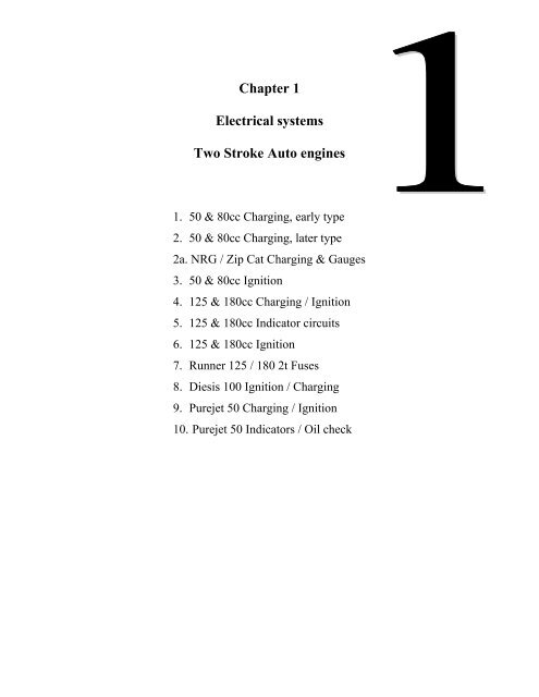
Chapter 1<br />
Electrical systems<br />
Two Stroke Auto engines<br />
1. 50 & 80cc Charging, early type<br />
2. 50 & 80cc Charging, later type<br />
2a. NRG / Zip Cat Charging & Gauges<br />
3. 50 & 80cc Ignition<br />
4. 125 & 180cc Charging / Ignition<br />
5. 125 & 180cc Indicator circuits<br />
6. 125 & 180cc Ignition<br />
7. Runner 125 / 180 2t Fuses<br />
8. Diesis 100 Ignition / Charging<br />
9. Purejet 50 Charging / Ignition<br />
10. Purejet 50 Indicators / Oil check
Chapter 2<br />
Electrical Systems<br />
Vehicles with LEADER Engines<br />
1. B125 / 200 Ignition / Charging<br />
2. B125 Notes<br />
3. B125 Fuse Explanation<br />
4. DNA 125 / 180 Ign. / Charging<br />
5. DNA 125 / 180 Switch Wiring<br />
6. ET4 125 Ignition / Charging<br />
7. Hexagon GTX Ign. / Charging<br />
8. Runner VX / VXR Ign. / Charging<br />
9. X9 125 / 180 Ignition / Charging<br />
10. Zip 125 Ignition / Charging<br />
11. General Notes<br />
12. Immobiliser Notes<br />
13. Vespa GT 125 / 200 Ignition / Charging<br />
14. Vespa GT 125 / 200 Fuses
Chapter 3<br />
Electrical Systems<br />
Four Stroke (Non Leader)<br />
1. Coguar 125 Ignition / Charging<br />
2. ET4 (ZAPM04) Early Charging<br />
3. ET4 (ZAPM04) Late Charging<br />
4. ET4 (ZAPM04) Immobiliser Notes<br />
5. Hexagon GTX 250 Ign./ Charging<br />
6. Liberty 125(non Leader) Charging<br />
7. X9 250 Ignition / Charging<br />
8. X9 250 Notes<br />
9. X9 250 Fuse Explanation<br />
10. 50cc 4 stroke Ignition / Charging<br />
11. 50cc 4 stroke Restriction Notes
Chapter 4<br />
Electrical Systems<br />
Two Stroke<br />
Manual Engines<br />
1. H@k / GSM Ignition / Charging<br />
2. H@K / GSM Notes<br />
3. H@K / GSM Wiring Diagram<br />
4. Vespa PX Ignition / Charging<br />
5. Vespa PX Start Permissive Circuit<br />
6. Vespa PX Indicator Circuit<br />
7. Vespa T5 Horn circuit<br />
8. Gilera RCR 50 Ignition / Charging
Chapter 5<br />
Electrical Systems<br />
General<br />
1. X9 Range General Notes<br />
2. X9 Range. Under the front Panel<br />
3. Stator Coil Values - Quick Ref.<br />
4. Auto Choke Operation<br />
5. Fuel Gauge Circuit<br />
6. Digital Instrument Display Notes
Chapter 6<br />
Fuel Systems<br />
1. Typhoon 80 / 125 Fuel System<br />
2. DNA Fuel Systems<br />
3. Hexagon (EXS1T) Fuel System<br />
4. Pumped Fuel Systems<br />
5. Vespa PX Fuel Tap
Chapter 7<br />
Mechanical Systems<br />
1. Fitting Main Bearings. All 2t autos.<br />
2. Vespa PX Clutch assy.<br />
3. Piston & Small End Sizes<br />
4. Up Side Down Forks<br />
5. Spark Plug List<br />
6. Oil List<br />
7. Tyres / Wheels <strong>Piaggio</strong><br />
8. Tyres / Wheels Gilera<br />
9. Keys Gilera<br />
10. Keys General<br />
11. Alarm Fitment List<br />
12. De-Restriction Notes<br />
13. Chassis Number Location<br />
14. Quick Reference Guide<br />
15. Service Limit List
Indicator<br />
Control Unit<br />
Purejet 50 Turn Signals & Oil check<br />
02/05/2003<br />
<strong>Piaggio</strong> Ltd. Runner<br />
B<br />
E<br />
S<br />
L<br />
White<br />
Black<br />
Yellow<br />
Black / Blue<br />
Left Turn Indicators<br />
Ignition Switch<br />
Grey / Red<br />
Orange<br />
White<br />
White / Red<br />
Red / Blue<br />
White<br />
ON<br />
7.5 amp Fuse's<br />
in Horn<br />
Compartment<br />
Yellow<br />
Black / Blue<br />
Blue<br />
15 amp<br />
Fuse's in<br />
Battery<br />
Compartment<br />
Oil Tank<br />
Sender<br />
Turn<br />
Indicator<br />
Switch<br />
Pink White / Blue<br />
Pink<br />
White / Blue<br />
+<br />
Red<br />
BATTERY<br />
12v<br />
Yellow<br />
Low Oil<br />
Warning<br />
Light<br />
* The low oil warning light check function is controlled by the indicator relay.<br />
* The oil check light should come on for 15 seconds when the ignition is first turned on.<br />
* If the system fails: first check the 7.5 amp fuse located under the front grill (horn) panel.<br />
1 - 10<br />
Right Turn Indicators
11/06/02<br />
<strong>Piaggio</strong> Ltd. Derbi engine<br />
Yellow / Green<br />
To<br />
starter<br />
solenoid<br />
+<br />
Rectifier /<br />
Regulator<br />
Red<br />
4<br />
amp<br />
Red<br />
DC Supply<br />
Red<br />
BATTERY<br />
12v<br />
4ah<br />
DIESIS 100 Charging / Ignition<br />
White<br />
Orange<br />
White / Red<br />
Yellow<br />
Yellow<br />
Yellow / Green<br />
Earth wires are - Yellow / green.<br />
Yellow wire is AC supply.<br />
Red / Blue wire is DC supply.<br />
Engine earth is very important.<br />
Carb heater is driven by AC power via a thermostat.<br />
No separate Ignition pick up, CDI is triggered by the AC wave.<br />
Ignition is earthed to stop the engine.<br />
Indicators<br />
AC Supply<br />
+ 5 o C<br />
Thermostat<br />
Black<br />
Black<br />
RIGHT<br />
OFF<br />
LEFT<br />
Red / Blue<br />
Red<br />
Yellow / Green<br />
Yellow / Green<br />
Pink<br />
White / Red<br />
Yellow / White<br />
Black / Red<br />
Green / Black<br />
Carb. Heater<br />
Orange - Indicator switch<br />
Yellow - AC circuit<br />
Green / Black<br />
Ignition Switch<br />
LOCK<br />
OFF<br />
ON<br />
NGK<br />
B9 ES<br />
Green<br />
Orange<br />
Black Red / White<br />
Explanation of Rectifier / regulator wiring<br />
Regulator<br />
Indicator<br />
Relay<br />
Red / Blue - DC supply<br />
White / Red - Stator<br />
Rectifier<br />
&<br />
Regulator<br />
TESTS.<br />
Stator: Yellow - Earth = min 25 v AC. White / Red - Earth = min 30 v AC. Engine at mid rpm.<br />
Yellow - Earth = 0.9 ohm + 0.2. White / Red - Earth = 1.1ohm + 0.2. Stator un-plugged.<br />
Black / Red - Earth = 238 ohm + 10%. Stator un-plugged.<br />
Regulator: Yellow - Earth = 13.5 + 0.5 v AC. White / Red - Earth = 13.5 + 1.0 v DC. Engine at mid rpm.<br />
Ignition: HT coil secondary resistance = 5 - 6 K ohm. Unit un-plugged.<br />
8<br />
Red - Battery<br />
Green / Black
RED / BLACK<br />
WHITE / RED<br />
GREY / BLACK<br />
Circuits protected by each fuse.<br />
FUSE EXPLANATION<br />
Runner FX 125 & FXR 180<br />
1. Head light flash (passing light).<br />
2. Indicators. Brake light. Oil indicator. Electric start relay. Temp gauge. Fuel gauge. Horn.<br />
Choke.<br />
3. Headlight relay. Town light. Rear light (lighting switch)<br />
4. Both headlights (power)<br />
Notes.<br />
• Ignition circuit is completely separate and self powered. It does not have any fuses.<br />
• The cooling fan is permanently live and is protected by the main 25 amp fuse.<br />
• The starter motor supply is not fused.<br />
Relation between lighting and the fuses.<br />
High Beam<br />
Low Beam<br />
GREY<br />
7.5 amp 1<br />
7.5 amp 2<br />
10 amp 3<br />
10 amp 4<br />
High / Low<br />
Switch<br />
Head Light<br />
Flash<br />
<strong>Piaggio</strong> Ltd. May 2000<br />
7<br />
WHITE<br />
WHITE<br />
WHITE<br />
RED<br />
Headlight<br />
Relay<br />
Lighting<br />
Switch<br />
+12v when<br />
ignition is ON<br />
Permanent +12v<br />
via 25 amp fuse<br />
From Fuse<br />
#<br />
1<br />
4<br />
3
<strong>Piaggio</strong> Ltd.<br />
STAT OR<br />
IGNITION TIMING IS CDI CONTROLLED<br />
Not adjustable<br />
Skipper and Typhoon:<br />
Ignition is fixed at 19 degrees.<br />
Hexagon and Runner:<br />
Two position ignition (not progressive).<br />
9 deg @ 1500+ rpm. Then 22 deg @ 7500+<br />
STATOR TEST VALUES. Stator un-plugged<br />
NOTES.<br />
Meter between ><br />
Hexagon LX / L XT<br />
Runner FX / F XR<br />
Skipper / Typhoon 125<br />
To test ><br />
125 / 180 2T Ignition<br />
Red - Brown<br />
23/01/2003<br />
BROWN<br />
* The ignition circuit is a separate self-contained circuit with no fuses and no connection to the other<br />
electrical circuits on the vehicle. It has a separate charging coil in the stator (Green & White wires).<br />
RED<br />
GREEN BLACK<br />
WHITE<br />
* The ignition switch contacts are OPEN when the engine is RUNNING. Contacts are CLOSED when<br />
switch is turned OFF, this allows the system to discharge to earth. When fault finding, if there is no spark<br />
then check the "green" and "purple" wires to see if there is a "leak" to earth. Unplug stator & CDI, check<br />
green to earth: Ignition on = no continuity. Ignition off = continuity.<br />
* A "Resistor" type spark plug and a resistor plug cap should always be fitted.<br />
Pick - up Co il<br />
90 - 140 ohm<br />
90 - 140 ohm<br />
90 - 140 ohm<br />
* This circuit does not require the engine to chassis earth. But if that earth lead is missing it is possible that<br />
trying to use the starter motor could force excess current through the CDI and damage it.<br />
Always prove you have a good engine to chassis earth connection.<br />
GREEN<br />
IGNITION SWITCH<br />
R B W G V<br />
6<br />
CDI UNIT<br />
White - Green<br />
Charge Coil<br />
50 - 100 ohm<br />
50 - 100 ohm<br />
100 - 160 ohm<br />
ON<br />
OFF<br />
PURPLE<br />
Purple - Earth<br />
HT Primary<br />
0.5 0.025 + ohm<br />
0.5 0.025 + ohm<br />
0.5 0.025 + ohm<br />
Hexagon LX / LXT<br />
Runner FX / FXR<br />
Skipper & Typhoon 125<br />
HT lead - Earth<br />
HT Secondary<br />
4.8 0.25 + k ohm<br />
4.8 0.25 + k ohm<br />
4.8 0.25 +<br />
k ohm
L<br />
125 / 180 Two Stroke INDICATOR CIRCUIT<br />
BE<br />
06/08/2002<br />
<strong>Piaggio</strong> Ltd <strong>Piaggio</strong> Ltd<br />
INDICATOR<br />
RELAY<br />
S<br />
B<br />
BLACK / BLUE<br />
BLACK<br />
BLUE / RED<br />
LOW OIL<br />
WARNING<br />
SWITCH<br />
YELLOW<br />
STARTER<br />
RELAY<br />
+ 12V DC<br />
INDICATOR SWITCH<br />
STOP SWITCH<br />
ABOVE. Vehicles 1999> Cirduit with oil check light that comes on when ignition is switched on.<br />
Refer to the Service Station Manual. Also Technical Notes 2/99 and 3/99.<br />
STARTER<br />
SWITCH<br />
YELLOW<br />
OIL WARNING<br />
LAMP<br />
BELOW. Vehicles
PURPLE<br />
<strong>Piaggio</strong> Ltd<br />
125 & 180cc 2t charging / Ignition<br />
Typhoon, Skipper, Hexagon, Runner<br />
CDI<br />
Unit<br />
GREEN<br />
13/08/2002<br />
BATTERY<br />
12v<br />
IGNITION SWITCH<br />
RED<br />
WHITE<br />
BROWN<br />
RED<br />
GREEN<br />
NOTES<br />
* Choke and Carb' heater will have a supply with ignition turned on but the<br />
rectifier / regulator will only complete the circuit to earth when it detects a<br />
charge. I.e. the engine is running.<br />
* The Charge warning light goes out when the engine is charging because +12v<br />
D.C. is applied to both sides of the bulb, not because the circuit is broken.<br />
* On water cooled engines the cooling fan is always live, the thermostat switch is<br />
on the earth side. So a battery going flat could be caused by a faulty fan or fan<br />
switch.<br />
* The starter solenoid is always live so is a possible cause of a battery going flat<br />
TESTS<br />
1. Stator Output.<br />
Yellow to Yellow 27 - 31 v A.C.@ 2000 rpm. Unplug regulator.<br />
Green - White 50 -150 ohm. Runner & Hexagon.(Stator un-plugged)<br />
100 -160 ohm. Skipper & Typhoon.(Stator un-plugged)<br />
Red - Brown 90 -140 ohm. All models. (Stator un-plugged)<br />
2. Charging.<br />
Between Red & Battery positive: >< 8.5 amps@ 2000 rpm with a fully<br />
charged battery (13.5v)<br />
3. Battery voltage must be present at terminal "C" with ignition on or the output<br />
from terminal B will be unregulated. Battery will boil, bulbs will blow etc.<br />
MAIN FUSE:<br />
Runner (ZAPM07 / 08) 25 amp.<br />
Hexagon (EXS1T & ZAPM05 / 06) 25 amp.<br />
Typhoon (ZAPM02) 15 amp.<br />
Skipper (CSM1T) 7.5 amp.<br />
ON<br />
OFF<br />
SUPPLY<br />
TO<br />
SYSTEMS<br />
+<br />
RED<br />
GREY<br />
IGNITION<br />
PICK UP<br />
FUSE<br />
RED<br />
YELLOW<br />
COOLING FAN<br />
ON<br />
WATER COOLED<br />
MODELS<br />
WHITE<br />
Choke Unit Carb. Heater<br />
4<br />
CHARGE<br />
WARNING<br />
LIGHT<br />
GREY<br />
A<br />
BROWN<br />
Choke<br />
Control<br />
STATOR<br />
WHITE<br />
L C<br />
RED<br />
Out put only when<br />
charging<br />
B<br />
YELLOW<br />
YELLOW<br />
G<br />
YELLOW<br />
G<br />
DC<br />
Rectifier<br />
Regulator
NOTES<br />
50cc 2t Ignition<br />
19/07/02<br />
<strong>Piaggio</strong> Ltd <strong>Piaggio</strong> Ltd<br />
This circuit could apply to any 50cc two stroke with or without a rev counter<br />
GREEN<br />
Champion NR2C<br />
NGK BR9ES<br />
WHITE<br />
CDI / COIL<br />
CDI / COIL<br />
unit<br />
unit<br />
RED<br />
IGNITION SWITCH<br />
ON<br />
OFF<br />
GREEN<br />
GREEN<br />
COMMON EARTH<br />
FOR<br />
INSTRUMENT PANNEL<br />
IGNITION PICK UP<br />
TESTS<br />
1. UNPLUG STATOR and CDI. GREEN WIRE SHOULD BE<br />
EARTHED WHEN IGNITION IS "OFF"<br />
2. CHECK CHARGING COIL.<br />
GREEN TO WHITE = 980 ± 50 ohms.<br />
3. CHECK TRIGGER COIL.<br />
RED TO WHITE = 88 ± 5 ohms.<br />
4. SPARK PLUG<br />
NRG's are now supplied with Champion N1C plugs<br />
The NGK equlivilent is B10ES.<br />
This plug is very cold running and may not suit all riders.<br />
If you find that a machine is fouling plugs try fitting an<br />
NGK B9ES.<br />
1<br />
REV COUNTER<br />
Ignition<br />
Charging Coil<br />
STATOR<br />
White wire is a common, dedicated earth.<br />
If the engine earth wire was missing the engine would run but you may have problems with the CDI unit failing because the<br />
electrical system may try to use the white wire as its earth connection.<br />
Green wire will have 150-200v AC when engine is running.<br />
3<br />
GREEN<br />
WHITE<br />
RED
GREY / BLUE<br />
1<br />
FUEL<br />
SENDER<br />
UNIT<br />
AC<br />
SERVICES<br />
Head light<br />
Tail light<br />
Instruments<br />
NRG & ZIP Cat. Charging & Guages<br />
02/05/2003<br />
<strong>Piaggio</strong> Ltd. 8 pin regulator<br />
WHITE<br />
YELLOW<br />
WHITE / GREEN<br />
IGNITION<br />
SWITCH<br />
BLUE<br />
RED / WHITE<br />
BLUE WHITE<br />
FUEL GUAGE<br />
FUEL<br />
FUEL<br />
WARNING<br />
LIGHT<br />
YELLOW / GREEN<br />
CHOKE UNIT<br />
OIL<br />
WARNING<br />
LIGHT<br />
TESTS<br />
1. Grey / Blue to earth = 25-30v AC<br />
stator un-plugged and engine at 2000rpm.<br />
2. Yellow to Blue = 26-30v AC<br />
stator and battery disconnected and engine at<br />
2000 rpm.<br />
3. Ammeter between red wire and battery positive<br />
= 1.5-2 amp with fully charged battery and<br />
engine at 2000 rpm.<br />
4. Output to the indicator switch will be a 12v DC<br />
pulse with ignition on.<br />
5. 12v DC for 15 seconds after ignition is turned on<br />
With sender unplugged.<br />
NOTES.<br />
* Wires at terminals 3 & 4 could be reversed.<br />
* Engine must be earthed to the chassis / battery.<br />
Lack of this connection will affect the AC circuit and<br />
starter motor but not the DC circuit or ignition circuit.<br />
2<br />
WHITE<br />
OIL TANK<br />
SENDER<br />
GREY<br />
1 - 2 a<br />
WHITE / VIOLET<br />
7.5 amp<br />
FUSE<br />
RED<br />
+<br />
BATTERY<br />
12v<br />
The NRG / Zip Cat wiring is very similar to other 50 / 80 scooters.<br />
Refer to page 2 (50 / 80 Charging) and page 3 (50cc 2t Ignition) for other information.<br />
BROWN<br />
WHITE / VIOLET<br />
5<br />
GREY / BLUE<br />
BLUE / RED<br />
BLACK<br />
1 2 3 4 5 6 7 8<br />
REGULATOR<br />
BLUE / RED<br />
BROWN<br />
YELLOW / GREEN<br />
5<br />
WHITE / VIOLET<br />
TIMER<br />
3<br />
BLUE / RED<br />
DC SERVICES<br />
Brake light<br />
Horn<br />
TO INDICATOR<br />
SWITCH<br />
BLUE / BLACK<br />
RECTIFIER<br />
&<br />
REGULATOR<br />
4<br />
YELLOW
1<br />
AC<br />
SERVICES<br />
Head light<br />
Tail light<br />
Instruments<br />
50 / 80cc 2T charging<br />
06/08/2002<br />
<strong>Piaggio</strong> Ltd. 8 pin regulator<br />
CHOKE UNIT<br />
YELLOW<br />
BLUE<br />
GREY / BLUE<br />
OIL<br />
WARNING<br />
LIGHT<br />
BLUE<br />
GREY<br />
GREY / BLUE<br />
2<br />
RED / WHITE<br />
IGNITION<br />
SWITCH<br />
WHITE<br />
7.5 amp<br />
FUSE<br />
RED<br />
+<br />
BATTERY<br />
12v<br />
DC SERVICES<br />
Brake light<br />
Horn<br />
* This diagram shows the later 50cc and 80cc two stroke wiring using an eight pin connector on the rectifier /<br />
regulator. Refer to the separate diagram for earlier circuit using a five pin rectifier / regulator.<br />
* RECOGNISE THIS CIRCUIT: If the oil warning light comes on for 15 seconds when ignition is turned on.<br />
* Two completely separate circuits for AC & DC.<br />
* Eight pin rectifier / regulator incorporates the indicator relay and oil light check function.<br />
* The choke is supplied with 12v AC when the engine is running .<br />
TESTS.<br />
1. Grey / Blue to earth = 25-30v AC stator un-plugged and engine at 2000rpm.<br />
2. Yellow to Blue = 26-30v AC stator and battery disconnected and engine at 2000 rpm.<br />
3. Ammeter between red wire and battery positive = 1.5-2 amp with fully charged battery and engine at 2000 rpm<br />
4. Output to the indicator switch will be a 12v DC pulse with ignition on.<br />
NOTES.<br />
Engine must be earthed to the chassis / battery. Lack of this connection will affect the AC circuit and starter motor<br />
but not the DC circuit or ignition circuit.<br />
WHITE<br />
BLACK<br />
3<br />
RECTIFIER<br />
&<br />
REGULATOR<br />
BLUE / BLACK<br />
NOT<br />
USED<br />
YELLOW<br />
1 2 3 4 5 6 7 8<br />
REGULATOR<br />
OIL TANK<br />
SENDER<br />
OIL<br />
LIGHT<br />
TIMER<br />
2<br />
4<br />
TO INDICATOR<br />
SWITCH
1<br />
50 / 80cc 2T charging<br />
02/05/2003<br />
<strong>Piaggio</strong> Ltd. 5 pin regulator<br />
AC<br />
SERVICES<br />
Head light<br />
Tail light<br />
Instruments<br />
CHOKE UNIT<br />
BLUE<br />
YELLOW<br />
GREY / BLUE<br />
2<br />
GREY<br />
A<br />
GREY<br />
IGNITION<br />
SWITCH<br />
A<br />
REGULATOR<br />
GREY / BLUE<br />
BLUE<br />
RED<br />
WHITE<br />
7.5 amp<br />
FUSE<br />
RED<br />
+<br />
BATTERY<br />
12v<br />
DC SERVICES<br />
Brake light<br />
Horn<br />
* This diagram shows the early 50cc and 80cc two stroke wiring using a five pin connector on the rectifier /<br />
regulator. Refer to the separate diagram for later circuit using an eight pin rectifier / regulator.<br />
* RECOGNISE THIS CIRCUIT: If the oil warning light comes on when the starter button is pressed.<br />
* Two completely separate circuits for AC & DC.<br />
AC is full wave and regulated<br />
DC is half wave rectified and regulated<br />
* If voltage at the B+ terminal falls below 8v (approx) the DC rectifier / regulator will not function so there will be no<br />
output from the <strong>alt</strong>ernator on the DC circuit.<br />
* Separate indicator relay.<br />
* The choke is supplied with 12v AC when the engine is running .<br />
TESTS.<br />
1. Grey / Blue to earth = 25-30v AC stator un-plugged and engine at 2000rpm.<br />
2. Yellow to Blue = 26-30v AC stator and battery disconnected and engine at 2000 rpm.<br />
3. Ammeter between red wire and battery positive = 1.5-2 amp with fully charged battery and engine at 2000 rpm<br />
NOTES.<br />
Engine must be earthed to the chassis / battery. Lack of this connection will affect the AC circuit and starter motor<br />
but not the DC circuit or ignition circuit.<br />
1 - 1<br />
ON<br />
OFF<br />
YELLOW<br />
G<br />
RED<br />
WHITE<br />
B+<br />
RECTIFIER<br />
&<br />
REGULATOR<br />
BLACK<br />
3<br />
12v 4ah - 50cc<br />
12v 5ah - 80cc
YELLOW<br />
YELLOW<br />
PUREJET 50 IGNITION / CHARGE<br />
02/09/2003<br />
<strong>Piaggio</strong> Ltd. GILERA RUNNER<br />
STATOR<br />
~ ~ ~ +<br />
RECTIFIER / REGULATOR<br />
BLUE<br />
YELLOW<br />
BROWN<br />
PICK UP<br />
BATTERY<br />
12v<br />
RED<br />
+<br />
RED<br />
15 amp<br />
BLUE<br />
RED / BLUE<br />
BLACK / VIOLET<br />
ON<br />
OFF<br />
ORANGE<br />
BLACK / VIOLET<br />
1 2 3 4 5 6 7 8 9 10 11 12 13 14 15 16 17 18 19 20 21 22<br />
SYSTEM NOTES.<br />
* 3 Phase AC.<br />
* Permanent live battery feed to Rectifier, ECU, HT Coil (blue wire). Any of these could drain the battery if they were faulty.<br />
* HT Coil is trigered by the BLACK / VIOLET wire being earthed via the ECU.<br />
FUSE<br />
15 amp<br />
To starter<br />
relay<br />
IGNITION SWITCH<br />
TESTS:<br />
Stator: Disconected. Any yellow to any yellow = 0.7 - 0.9 ohm. Any yellow to earth = No continuity<br />
Pick Up coil value is not quoted.<br />
Rectifier / Regulator: With a charged battery the possible voltage must not exceed 15.2 volts.<br />
1-9<br />
BLUE<br />
BLUE<br />
Champion<br />
RG6YCA<br />
BLUE<br />
ECU<br />
BLUE<br />
ORANGE<br />
HT COIL<br />
RED<br />
BROWN
+<br />
13/08/2003<br />
<strong>Piaggio</strong> Ltd. NO Immobiliser<br />
Rectifier /<br />
Regulator<br />
p/n: 82501R<br />
ZIP 125 Leader engine ignition / charging<br />
ALTERNATOR<br />
G STATOR<br />
15<br />
amp<br />
Red<br />
Ignition<br />
Pick up<br />
Yellow<br />
To<br />
Indicator<br />
switch<br />
BATTERY<br />
12v<br />
9ah<br />
Red / Blue<br />
Black<br />
Blue / Black<br />
ON<br />
OFF<br />
LOCK<br />
2-10<br />
Purple<br />
Ignition<br />
Switch<br />
Orange<br />
RG6YC<br />
CR 7EB<br />
HT Coil<br />
3 2 1<br />
8 7 6 5 4<br />
Layout of pins<br />
in the CDI<br />
Orange<br />
Power<br />
to<br />
services<br />
Carb. Heater<br />
Choke Unit<br />
White /<br />
Black<br />
6 1 8 3 4 5 7 2<br />
ECU<br />
Green<br />
Green<br />
GREEN<br />
WHITE / BLACK<br />
ORANGE<br />
PURPLE<br />
BLACK<br />
BLUE / BLACK<br />
CDI CONNECTIONS<br />
1. BLUE / BLACK - INDICATOR SWITCH SUPPLY<br />
2. GREEN - INPUT FROM IGNITION PICK UP<br />
3. PURPLE - TO HT COIL<br />
4.<br />
5. ORANGE - SUPPLY FROM IGNITION SWITCH<br />
6.<br />
7. WHITE / BLACK - CHOKE CONTROL<br />
8. BLACK - EARTH<br />
TESTS.<br />
Yellow - Yellow. Charging coils. 0.7 - 0.9 ohm<br />
Yellow - Earth. No continuity<br />
Green - Earth. Ignition pick up coil. 105 - 124 ohm.<br />
Purple - Earth. Coil primary winding. 0.4 - 0.5 ohm<br />
HT - Earth. Coil secondary winding. 3000 ohm
+<br />
19/07/02<br />
<strong>Piaggio</strong> Ltd. With IMMOBILISER<br />
ALTERNATOR<br />
G STATOR<br />
Rectifier /<br />
Regulator<br />
p/n: 82501R<br />
Headlight<br />
via relay<br />
Grey<br />
/ Red<br />
Red<br />
15<br />
amp<br />
BATTERY<br />
12v<br />
10ah<br />
Runner VX / VXR ignition / charging<br />
Ignition<br />
Pick up<br />
Yellow<br />
Red<br />
Red<br />
Red / Blue<br />
To<br />
Indicator<br />
switch<br />
Red / Blue<br />
Ignition<br />
Switch<br />
Black<br />
Diagnostic<br />
socket<br />
NGK<br />
CR 8EB<br />
HT Coil<br />
Orange<br />
Red<br />
Purple<br />
Blue / Black<br />
3 2 1<br />
8 7 6 5 4<br />
Layout of pins<br />
in the ECU / immobiliser<br />
Yellow<br />
ON<br />
OFF<br />
Red<br />
Green<br />
Fan<br />
Switch<br />
Yellow / Red<br />
Cooling<br />
Fan<br />
White /<br />
Black<br />
Red<br />
Red / Blue<br />
Choke Unit<br />
6 1 8 3 4 5 7 2<br />
antenna<br />
Power to<br />
services<br />
GREEN<br />
WHITE / BLACK<br />
RED / BLUE<br />
RED<br />
PURPLE<br />
BLACK<br />
BLUE / BLACK<br />
YELLOW<br />
Green<br />
5<br />
amp<br />
Green<br />
ECU / Immobiliser<br />
LED on<br />
instrument<br />
pannel<br />
TESTS.<br />
STATOR: ANY YELLOW TO ANY YELLOW = 0.7 - 0.9 ohm.<br />
YELLOW TO EARTH = NO CONTINUITY<br />
GREEN TO BLACK (EARTH) = 105 - 124 ohm<br />
REGULATOR: VOLTAGE ACROSS A FULLY CHARGED BATTERY,<br />
LIGHTS OFF, HIGH REVS = 14 - 15.2 V.<br />
CHARGING: AMMETER IN RED WIRE = > 8 AMPS<br />
WITH LIGHTS ON AND HIGH REVS.<br />
HT COIL: PRIMARY = 0.4 - 0.5 OHM. SECONDARY = 3K + 300 OHM.<br />
2-8
15<br />
amp<br />
+<br />
13/03/02<br />
<strong>Piaggio</strong> Ltd. With IMMOBILISER<br />
ALTERNATOR<br />
G STATOR<br />
Rectifier /<br />
Regulator<br />
p/n: 82501R<br />
Red<br />
BATTERY<br />
12v<br />
12ah<br />
Hexagon GTX 125 ignition / charging<br />
Ignition<br />
Pick up<br />
Orange<br />
5<br />
amp<br />
5<br />
amp<br />
White<br />
Yellow<br />
Red<br />
Red<br />
To<br />
Indicator<br />
switch<br />
Black<br />
Diagnostic<br />
socket<br />
ON<br />
OFF<br />
Orange<br />
RG4HC<br />
CR 9EB<br />
HT Coil<br />
Ignition<br />
Switch<br />
Red<br />
Purple<br />
Blue / Black<br />
3 2 1<br />
8 7 6 5 4<br />
Layout of pins<br />
in the ECU / immobiliser<br />
Red<br />
Yellow<br />
Green<br />
Fan<br />
Switch<br />
Orange<br />
Yellow / Blue<br />
Red / Blue<br />
Lt. Blue<br />
Cooling<br />
Fan<br />
6 1 8 3 4 5 7 2<br />
White<br />
/ Black<br />
Green<br />
Orange<br />
Green<br />
ECU / Immobiliser<br />
antenna<br />
Choke Unit<br />
RUN<br />
STOP<br />
GREEN<br />
WHITE / BLACK<br />
Lt. BLUE<br />
RED<br />
PURPLE<br />
BLACK<br />
BLUE / BLACK<br />
YELLOW<br />
LED on<br />
instrument<br />
pannel<br />
TESTS.<br />
STATOR: ANY YELLOW TO ANY YELLOW = 0.7 - 0.9 ohm.<br />
YELLOW TO EARTH = NO CONTINUITY<br />
GREEN TO BLACK (EARTH) = 105 - 124 ohm<br />
REGULATOR: VOLTAGE ACROSS A FULLY CHARGED BATTERY,<br />
LIGHTS OFF, HIGH REVS = 14 - 15.2 V.<br />
CHARGING: AMMETER IN RED WIRE = > 8 AMPS<br />
WITH LIGHTS ON AND HIGH REVS.<br />
HT COIL: PRIMARY = 0.4 - 0.5 OHM. SECONDARY = 3K + 300 OHM.<br />
2-7
13/03/02<br />
<strong>Piaggio</strong> Ltd. With IMMOBILISER<br />
ALTERNATOR<br />
G STATOR<br />
Rectifier /<br />
Regulator<br />
p/n: 82501R<br />
Headlight<br />
via relay<br />
Grey<br />
+<br />
Red<br />
15<br />
amp<br />
ET4 Leader engine ignition / charging<br />
BATTERY<br />
12v<br />
9ah<br />
Ignition<br />
Pick up<br />
Yellow<br />
Red / Blue<br />
To<br />
Indicator<br />
switch<br />
Red / Blue<br />
Black<br />
Blue /<br />
Black<br />
White<br />
ON<br />
OFF<br />
Red / Blue<br />
Ignition<br />
Switch<br />
RG4HC<br />
CR 9E<br />
HT Coil<br />
Orange<br />
7.5<br />
amp<br />
Purple<br />
Diagnostic<br />
socket<br />
3 2 1<br />
8 7 6 5 4<br />
Layout of pins<br />
in the ECU / immobiliser<br />
Orange<br />
Red /<br />
Blue<br />
Orange<br />
Yellow<br />
Red / Blue<br />
White /<br />
Black<br />
Green<br />
Power<br />
to<br />
services<br />
Carb. Heater<br />
Choke Unit<br />
6 1 8 3 4 5 7 2<br />
Green<br />
ECU / Immobiliser<br />
antenna<br />
GREEN<br />
WHITE / BLACK<br />
ORANGE<br />
RED / BLUE<br />
PURPLE<br />
BLACK<br />
BLUE / BLACK<br />
YELLOW<br />
LED on<br />
instrument<br />
pannel<br />
TESTS.<br />
STATOR: ANY YELLOW TO ANY YELLOW = 0.7 - 0.9 ohm.<br />
YELLOW TO EARTH = NO CONTINUITY<br />
GREEN TO BLACK (EARTH) = 105 - 124 ohm<br />
REGULATOR: VOLTAGE ACROSS A FULLY CHARGED BATTERY,<br />
LIGHTS OFF, HIGH REVS = 14 - 15.2 V.<br />
CHARGING: AMMETER IN RED WIRE = > 8 AMPS<br />
WITH LIGHTS ON AND HIGH REVS.<br />
HT COIL: PRIMARY = 0.4 - 0.5 OHM. SECONDARY = 3K + 300 OHM.<br />
2-6
1<br />
2<br />
<strong>Piaggio</strong> Ltd.<br />
3 4 5 6<br />
GREEN<br />
BLACK<br />
RED<br />
DNA 125 / 180 Switch Wiring<br />
ON<br />
OFF<br />
LOCK<br />
PARK<br />
BROWN<br />
YELLOW - BLACK<br />
WHITE<br />
INDICATORS MAIN / DIP<br />
LIGHTS<br />
RIGHT<br />
LEFT<br />
OFF<br />
ALL<br />
SIDE<br />
OFF<br />
WHITE - BLUE<br />
BLUE - BLACK<br />
PINK<br />
START<br />
PUSH<br />
0<br />
08/05/2003<br />
IGNITION SWITCH<br />
ITEM 6 ON WIRING DIAGRAM<br />
FLASH<br />
HIGH<br />
LOW<br />
Refer to Service Station Manual<br />
594329 (02/01) page 4-23><br />
FEED FROM LIGHT SWITCH. WHEN LIGHTS ARE TURNED ON<br />
SUPPLY TO REAR LIGHTS AND FRONT PILOT LIGHT<br />
MAIN SUPPLY TO IGNITION SYSTEM, LIGHTS ETC.<br />
MAIN FEED FROM BATTERY<br />
HORN<br />
PUSH<br />
BLACK<br />
GREY - BLACK<br />
YELLOW - BLACK<br />
BROWN<br />
PURPLE<br />
WHITE<br />
EMERGENCY<br />
STOP<br />
RUN<br />
WHITE<br />
YELLOW - RED<br />
GREEN - BLACK<br />
WHITE - BLACK<br />
ORANGE<br />
BROWN<br />
YELLOW<br />
2-5<br />
0<br />
0<br />
LEFT HAND<br />
SWITCHES<br />
ITEM 8<br />
ON WIRING DIAGRAM<br />
RIGHT HAND<br />
SWITCHES<br />
ITEM 9<br />
ON WIRING DIAGRAM<br />
ORANGE
13/08/2003<br />
<strong>Piaggio</strong> Ltd. DNA 125 / 180<br />
ALTERNATOR<br />
G STATOR<br />
Rectifier /<br />
Regulator<br />
p/n: 82501R<br />
+<br />
Headlight<br />
via relay<br />
White<br />
/ Pink<br />
Red<br />
15<br />
amp<br />
BATTERY<br />
12v<br />
12ah<br />
DNA Leader engine ignition / charging<br />
Ignition<br />
Pick up<br />
Yellow<br />
Red<br />
Red<br />
Green<br />
Fan<br />
Switch<br />
Red<br />
White / Black<br />
Ignition<br />
Switch<br />
White<br />
Connector for Alarm<br />
NGK<br />
CR 8EB<br />
Cooling<br />
Fan<br />
Yellow<br />
Blue / Red<br />
Green / Yellow<br />
Black<br />
7.5<br />
amp<br />
Orange<br />
Orange<br />
Blue / Red<br />
HT Coil<br />
ECU<br />
White / Black<br />
Yellow / Red<br />
7.5<br />
amp<br />
Power to<br />
Lights, horn<br />
instruments<br />
Lt. Blue / Green<br />
Choke Unit<br />
Green<br />
Green<br />
To<br />
Indicator<br />
switch<br />
Blue /<br />
Black<br />
3 2 1<br />
8 7 6 5 4<br />
STATOR: ANY YELLOW TO ANY YELLOW = 0.7 - 0.9 ohm. YELLOW TO EARTH = NO CONTINUITY<br />
GREEN TO BLACK (EARTH) = 105 - 124 ohm<br />
REGULATOR: VOLTAGE ACROSS A FULLY CHARGED BATTERY, LIGHTS OFF, HIGH REVS = 14 - 15.2 V.<br />
CHARGING: AMMETER IN RED WIRE = > 8 AMPS WITH LIGHTS ON AND HIGH REVS.<br />
HT COIL: PRIMARY = 0.4 - 0.5 OHM. SECONDARY = 3K + 300 OHM.<br />
2-4<br />
ON<br />
OFF<br />
RUN<br />
STOP<br />
Blue / Red
B 125 FUSE EXPLANATION<br />
08/05/2003<br />
<strong>Piaggio</strong> Ltd. <strong>Piaggio</strong> Ltd.<br />
WHITE<br />
12v DC from<br />
ignition switch<br />
GREY<br />
From light<br />
switch<br />
RED / BLUE<br />
Digital Panel, LED, Radio<br />
FRONT FUSE BOX<br />
1 4 amp<br />
2 4 amp<br />
3 7.5amp<br />
4 4 amp<br />
REAR FUSE BOX<br />
5<br />
4<br />
a<br />
YELLOW<br />
Headlight via relay<br />
RED<br />
12v DC from battery<br />
6<br />
10<br />
a<br />
2-3<br />
7<br />
15<br />
a<br />
WHITE / ORANGE<br />
Engine start, run, warning lights<br />
WHITE / RED<br />
Brake lights, start inhibit<br />
RED / GREY<br />
Horn, Headlight flash<br />
YELLOW<br />
Anologue, Inst. & side lights<br />
8<br />
15 a<br />
RED / BLACK<br />
General<br />
BLUE<br />
Under seat, Light, Socket, Lock
B 125 / 200 NOTES<br />
The notes should be used in conjunction with Service Station Manual 594845 and<br />
the notes “B 125 ignition / charging” and “B 125 Fuse Explanation”<br />
1. Seat has electric release. Only works when ignition switch is in the “off”<br />
position.<br />
If seat lock fails to operate:<br />
Check fuse “7” in rear fuse box. 4 amp red wire in & blue wire out.<br />
Check for power on Blue wire at ignition switch<br />
Check for power on White / Blue wire at ignition switch with ignition “off”.<br />
Check the push button, Blue / Black should earth when button is pressed.<br />
Seat lock, power socket and under seat light are all controlled by the same<br />
fuse.<br />
2. Wires from The engine.<br />
Three Yellow wires: Three phases of generator, all feed directly to the<br />
rectifier / regulator.<br />
Green wire: Ignition pick up. Goes to CDI unit.<br />
Brown wire: From oil pressure switch, goes to indicator light on instrument<br />
panel.<br />
3. Immobiliser is like other Leader engines. There are separate notes to explain<br />
the immobiliser system.<br />
4. Fuel system. (similar to the DNA 125 / 180 four strokes)<br />
Fuel is pumped from the tank and supplied to the carburettor under<br />
pressure.<br />
Fuel pump is on the bottom of the tank and is driven by manifold vacuum.<br />
The feed pipe from pump to carburettor has a non-return valve and an<br />
inline filter.<br />
200cc engine may (early vehicles) have a vacuum pipe that branches off<br />
to operate an over run valve in the carburettor.<br />
Carburettor icing is controlled by a warm water feed from the cooling<br />
system.<br />
Choke is the automatic (wax pellet) type used on all our automatics.<br />
Remember that these units default to being “ON” and are turned off<br />
electrically. They are more likely to cause running rich when hot than cold<br />
starting problems.<br />
5. Spark Plugs.<br />
Please note that the correct spark plugs are:<br />
125cc :- NGK CR8 EB p.n. 828866<br />
200cc :- Champion RG6 YC p.n. 828708 (or NGK CR7EB)<br />
2
Blue<br />
+<br />
Blue<br />
Red<br />
Yellow<br />
B 125 / 200 ignition / charging<br />
13/08/2003<br />
<strong>Piaggio</strong> Ltd. With IMMOBILISER<br />
Red / Black<br />
Red / Black<br />
15 15<br />
15<br />
Red / Blue<br />
4<br />
BATTERY<br />
12v<br />
10ah<br />
G<br />
Red / Blue<br />
Rectifier /<br />
Regulator<br />
p/n: 82501R<br />
HT Coil<br />
Purple<br />
Black<br />
Red / Black<br />
CR 9EB<br />
Ignition<br />
Pick up<br />
Green<br />
Green<br />
Ignition<br />
Switch<br />
Red / Black<br />
Ignition Relay<br />
White /<br />
Green<br />
Immobiliser<br />
LED<br />
White / Green<br />
Red / Black<br />
Cooling<br />
Fan<br />
White<br />
Yellow / Blue<br />
CDI CONNECTIONS<br />
1. BLUE / BLACK - INDICATOR SWITCH SUPPLY<br />
2. GREEN - INPUT FROM IGNITION PICK UP<br />
3. PURPLE - TO HT COIL<br />
4. RED / BLACK - 12v PERMANENT LIVE<br />
5. WHITE / GREEN - SUPPLY FROM IGNITION SWITCH<br />
6. YELLOW / BLUE - IMMOBILISER LED<br />
7. WHITE / BLACK - CHOKE CONTROL<br />
8. BLACK - EARTH<br />
2-1<br />
OFF<br />
Blue<br />
White / Blue<br />
White<br />
2<br />
1<br />
White<br />
Stand<br />
Warning<br />
Lt. Blue<br />
3 2 1<br />
8 7 6 5 4<br />
Green<br />
White / Black<br />
Green / Blue<br />
Lt. Blue<br />
Orange<br />
Fan<br />
Switch<br />
White /Orange<br />
ECU / Immobiliser<br />
White<br />
White<br />
Choke Unit White<br />
Black / Blue<br />
Red / Black<br />
White / Green<br />
Yellow / Blue<br />
Seat Lock Seat Release<br />
Push Button<br />
Blue / Black<br />
Indicator<br />
Switch<br />
antenna<br />
RUN<br />
STOP<br />
Emergency<br />
Stop<br />
UP<br />
Down<br />
Side Stand<br />
Switch<br />
4 amp<br />
White / Black
<strong>Piaggio</strong> Ltd.<br />
GREY<br />
RED / BLUE<br />
RED / BLACK<br />
12v DC from battery<br />
1<br />
10<br />
a<br />
WHITE<br />
RED / BLACK<br />
12v DC from battery<br />
ORANGE<br />
Switched 12v<br />
Vespa GT Fuses<br />
2<br />
7.5<br />
a<br />
19/08/2003<br />
3<br />
7.5<br />
a<br />
4<br />
7.5<br />
a<br />
YELLOW / RED<br />
5<br />
5<br />
a<br />
ORANGE<br />
Switched 12v<br />
WHITE / RED<br />
6<br />
5<br />
a<br />
YELLOW / BLACK<br />
BLUE<br />
BLUE<br />
The wire colours shown here are different to those "on line" and in the owners hand<br />
book.<br />
The colours and fuse functions here are correct, they were checked on GT200<br />
ZAPM312 * 2550.<br />
FUSE:<br />
1. 10 amp. Electric seat release. Headlights. Main beam warning light.<br />
2. 7.5 amp. Intercom. Alarm. Immobiliser LED.<br />
3. 7.5 amp. Intercom. Alarm. Water temp. Fuel warning & guage. Oil pressure warning.<br />
4. 7.5 amp. Horn.<br />
5. 5 amp. Stop light. start switch.<br />
6. 5 amp. Side lights. Number plate light. Instrument panel lights.<br />
MAIN FUSE.<br />
A 15 amp fuse is located at the front of the under seat compartment.<br />
2-14
+<br />
Vespa GT 125 / 200 ignition / charging<br />
18/08/2003<br />
<strong>Piaggio</strong> Ltd. With IMMOBILISER<br />
ALTERNATOR<br />
G STATOR<br />
Rectifier / Regulator<br />
p/n: 82501R<br />
Main<br />
15<br />
amp<br />
Red<br />
Ignition<br />
Pick up<br />
Red / Black<br />
Red / Black<br />
BATTERY<br />
12v<br />
12ah<br />
Yellow<br />
Fuses in<br />
glove box<br />
Red / Blue<br />
Seat release<br />
push button<br />
Grey / Black<br />
Red / Black<br />
Purple<br />
Black<br />
HT Coil<br />
To<br />
Indicator<br />
switch<br />
LED on<br />
instrument<br />
pannel<br />
Seat lock<br />
RG4HC<br />
CR 9EB<br />
2 -13<br />
Grey / Blue<br />
Grey<br />
Yellow<br />
Green<br />
Fan<br />
Switch<br />
Orange<br />
antenna<br />
OFF<br />
Choke Unit<br />
Lt. Blue<br />
Ignition<br />
Switch<br />
6 1 8 3 4 5 7 2<br />
Cooling<br />
Fan<br />
RUN<br />
STOP<br />
Orange<br />
White / Black<br />
Green<br />
Orange<br />
GREEN<br />
WHITE / BLACK<br />
Lt. BLUE<br />
RED / BLACK<br />
PURPLE<br />
BLACK<br />
BLUE / BLACK<br />
YELLOW<br />
Green<br />
ECU / Immobiliser<br />
3 2 1<br />
8 7 6 5 4<br />
Layout of pins<br />
in the ECU / immobiliser<br />
Note that the ECU fitted to the 125 and 200 have different characteristics.<br />
They are NOT interchangeable.<br />
TESTS.<br />
STATOR: ANY YELLOW TO ANY YELLOW = 0.7 - 0.9 ohm.<br />
YELLOW TO EARTH = NO CONTINUITY<br />
GREEN TO BLACK (EARTH) = 105 - 124 ohm<br />
REGULATOR: VOLTAGE ACROSS A FULLY CHARGED BATTERY,<br />
LIGHTS OFF, HIGH REVS = 14 - 15.2 V.<br />
CHARGING: AMMETER IN RED WIRE = > 8 AMPS<br />
WITH LIGHTS ON AND HIGH REVS.<br />
HT COIL: PRIMARY = 0.4 - 0.5 OHM. SECONDARY = 3K + 300 OHM.<br />
ON<br />
LOCK
LEADER Engine<br />
Ignition immobiliser<br />
For a full explanation of the immobiliser system please refer to the Service Station Manual.<br />
The system is very similar to that used on the original Vespa ET4 but there are subtle<br />
differences in operation, fault finding and component replacement. The CDI and immobiliser<br />
are now combined in one box.<br />
The vehicle is supplied with two keys. One MASTER key and one SERVICE key. Additional<br />
service keys are obtainable but it is not possible to duplicate the master key.<br />
TESTING.<br />
Normally do not use the master key for testing.<br />
Testing is done by using the instrument panel mounted LED.<br />
If the system is working normally the LED will be flashing steadily when the ignition is<br />
off and it will stop flashing when the ignition is on.<br />
If the vehicle has not been used for 48 hours the light will stop flashing to save the<br />
battery. It is restored by turning the ignition on and off.<br />
If the immobiliser system is faulty, when the ignition is switched on there will be a series<br />
of flashes. The flashes hold a key to the fault.<br />
Turn on ignition;<br />
1. The first flash will be long (2 seconds) or short (0.7 second). A Long flash means the<br />
system is not program<strong>med</strong>. A Short flash indicates that the system is program<strong>med</strong>.<br />
2. 2 second pause.<br />
3. Next is a series of short (0.5 second) flashes. These define a fault.<br />
1 flash = System is not program<strong>med</strong>. Engine can run but only up to 2000 rpm.<br />
2 flash = No key transponder detected. Fault with Key or antenna.<br />
3 flash = Key transponder detected but not recognised. See the notes below.<br />
4. The last thing to notice is whether the LED finally remains on or off.<br />
OFF = Ignition is possible.<br />
ON = Ignition is not possible.<br />
Notes.<br />
If the system is not program<strong>med</strong> the LED indicator may not be flashing with ignition off<br />
but it will perform the test function when the ignition is turned on.<br />
Wrong key. There are a limited number of mechanical codes used for the keys. It is<br />
possible that you could have two vehicles is stock that both have keys with the same<br />
mechanical code. If you put the wrong key in the wrong vehicle it will turn on the ignition<br />
but you will get the “transponder not recognised” fault code and the vehicle will not start.<br />
12<br />
1 of 2<br />
<strong>Piaggio</strong> Ltd October 2001
Examples.<br />
Turn Ignition On<br />
1 2 3<br />
2 sec<br />
2 sec<br />
0.7 sec<br />
0.7 sec<br />
0.7 sec<br />
2 x 0.5 sec<br />
2 x 0.5 sec<br />
3 x 0.5 sec<br />
LED off<br />
LED off<br />
LED off<br />
LED on<br />
LED on<br />
12<br />
2 of 2<br />
<strong>Piaggio</strong> Ltd October 2001<br />
System not program<strong>med</strong>.<br />
Engine will only run to 2000rpm.<br />
System not program<strong>med</strong>.<br />
Transponder not detected<br />
Engine will only run to 2000rpm.<br />
System functioning normally.<br />
CDI program<strong>med</strong>. Key transponder not detected.<br />
Fault with transponder or aerial.<br />
Ignition not possible<br />
CDI program<strong>med</strong>.<br />
Key transponder detected but not recognised.<br />
Ignition not possible.<br />
KEYS<br />
The machine is supplied with two keys. One large brown MASTER key (with a flip out section<br />
containing the chip) and One smaller SERVICE key.<br />
The MASTER key should be kept safely at home. Only use it for programming.<br />
The service key is the key that is used.<br />
If you require a new service key this can be ordered from Fowlers and then program<strong>med</strong> as follows:<br />
Programming New Keys.<br />
It’s an easy process but timing is very important.<br />
If the vehicle has a side stand it must be UP and the engine kill switch must be set to “RUN”<br />
1. Master key in and turn on for two seconds, turn off and remove<br />
2. Service key in and turn on for two seconds, turn off and remove (If you have other service keys<br />
repeat this with each one).<br />
3. Master key in and turn on for two seconds, turn off and remove<br />
A quicker easier <strong>alt</strong>ernative is to obtain a key from any automotive locksmith. The same system is<br />
common on cars, most locksmiths will have the blanks and the equipment to identify the chip in your<br />
key.<br />
They will cut a key and then fit the correct type of chip into it. This chip will have been “cloned” from<br />
your original so you will not need to programme this new key.<br />
If both keys are lost the only solution is to replace the CDI unit and the locks. A new lock set comes<br />
with a Master and a Service key.
LEADER ENGINE<br />
Ignition, charging & immobiliser<br />
Use these notes in conjunction with the SERVICE STATION MANUAL<br />
The electrical system on the new Leader engine is very different to previous two stroke and<br />
four stroke <strong>Piaggio</strong> engines. The ignition, charging & immobiliser circuits do not function in<br />
the same way and do not share common components with previous versions.<br />
Ignition is now using the battery circuit. Everything shares one common supply.<br />
Alternator has three phase (all yellow wires) and ignition pick up coil (green wire) outputs<br />
only.<br />
Rectifier / Regulator is very simple. Three phase (yellow) inputs and one output.<br />
CDI unit has become more complicated. The one unit is responsible for: ignition,<br />
immobiliser, indicators & choke unit.<br />
Much of the circuit is the same on ET4 Leader, Super Hexagon GTX 125, Liberty 125<br />
Leader, Skipper ST, Runner VX / VXR and DNA 125 / 180, X9 125 but be careful<br />
because there are differences. Early Skipper ST did not have an immobiliser, they do have<br />
it now.<br />
IGNITION.<br />
When the ignition is turned on power is supplied to the CDI (terminal 5).<br />
Ignition pick up is via green wire (terminal 2).<br />
Output to the HT coil is via purple wire (terminal 3).<br />
The unit is earthed via black wire (terminal 8).<br />
CDI / IMMOBILISER<br />
Note the CDI units have different part numbers for different models and engines size.<br />
Refer to the diagram for each specific model. The wiring and wire colours may vary.<br />
It is important that the correct part number is used as the ignition characteristics vary and<br />
<strong>alt</strong>hough the units look the same they are different!<br />
On vehicles with an immobiliser;<br />
The wires connected to the unmarked terminals are from the antenna that is mounted around<br />
the ignition lock barrel.<br />
Check antenna for continuity, unplugged resistance = 7 - 9 Ω.<br />
The red or red / blue wire (terminal 4) supplies battery voltage even with ignition off.<br />
Yellow wire (terminal 6) is from the LED on the instrument panel. If the system is<br />
program<strong>med</strong> and working correctly the LED should be flashing steadily with the ignition<br />
turned off to confirm that the immobiliser system is functioning. The immobiliser earths the<br />
LED (or not) to make it turn on or off.<br />
See pages 3-4 below for more details on using the LED for immobiliser fault finding.<br />
HT COIL. 82597R = Common to most Leader engines. 82582R = Skipper ST & X9 125<br />
Purple to Black - primary winding = 0.4 - 0.5 Ω<br />
HT to Black - secondary winding = 3000 ± 300 Ω<br />
Plugged in with engine cranking the peak voltage Purple to Earth = 100 vdc<br />
11<br />
1 of 2<br />
<strong>Piaggio</strong> Ltd October 2001
IGNITION PICK UP COIL.<br />
Un plug, check resistance, Green to Black = 105 - 124 Ω<br />
Un-plugged with engine cranking the peak voltage Green to Black = 2 vdc<br />
STATOR.<br />
Any yellow to yellow should give continuity. Un-plugged, yellow to yellow = 0.7 - 0.9 Ω<br />
Yellow to earth should not give continuity.<br />
RECTIFIER / REGULATOR. p/n 82501R common to leader engines.<br />
Regulated voltage. With a fully charged battery check charging rate by putting volt meter<br />
across the battery terminals. Peak voltage = 14 - 15.2 vdc. Engine at high speed and lights<br />
off.<br />
Charge current. Connect ammeter to the red wire. Then Start engine. Charge ≥ 10 amp.<br />
With the head light turned on.<br />
INDICATORS.<br />
There is no separate indicator relay. The relay function is contained within the CDI unit,<br />
Power to the indicator switch is via the blue / black wire (terminal 1).<br />
If the indicators fail first check that you are getting voltage at terminal 1 (blue/black)<br />
To check the switch and wiring. Unplug the CDI and link red/blue wire to blue/black wire,<br />
when the turn switch is operated the appropriate lights should come on. (you will not need the<br />
ignition to be turned on).<br />
CHOKE UNIT.<br />
The choke is now controlled by the CDI. (not the regulator).<br />
Power is supplied to the choke via the main switched wire from the ignition switch to the<br />
CDI. The unit will not function until the engine is running when the CDI will complete the<br />
circuit to earth (terminal 7).<br />
Un Plugged, resistance across the connections = >< 30 Ω @ 20˚C<br />
Plunger extension. Measure how far the plunger protrudes from the body when it is cold,<br />
this should be 12.5 - 13.0 mm. Now connect the choke unit to a 12v battery. The plunger<br />
should have extended to 18.5 - 19.0 mm within 5 minutes.<br />
Supply. Orange or Red / Blue to earth = Battery volts with ignition on.<br />
Orange or Red / Blue to White/Black = 13-14.5v dc (system volts) with engine running.<br />
CARB. HEATER. Fitted to air-cooled engines.<br />
The carb heater will start working as soon as the ignition is turned on. Power is supplied via<br />
the switched wire that goes to the CDI.<br />
Water cooled engines use a warm water connection from the cooling system.<br />
COOLING FAN. On water cooled engines.<br />
The live feed from battery to fan is permanently connected. The switch is in the earth from the<br />
fan. So if the fan is faulty it could be the cause of a flat battery.<br />
11<br />
2 of 2<br />
<strong>Piaggio</strong> Ltd October 2001
Rectifier /<br />
Regulator<br />
p/n: 82501R<br />
+<br />
X9 125 / 180 ignition / charging<br />
<strong>Piaggio</strong> Ltd. 25/10/02<br />
With IMMOBILISER<br />
ALTERNATOR<br />
G STATOR<br />
RG4HC<br />
CR 9EB<br />
15<br />
amp<br />
Red<br />
BATTERY<br />
12v<br />
12ah<br />
Ignition<br />
Pick up<br />
Yellow<br />
Red / Black<br />
HT Coil<br />
Purple<br />
Black<br />
Red / Black<br />
Red / Black<br />
Orange<br />
Lt. Blue<br />
Lt. Blue<br />
Orange<br />
Yellow / Green<br />
Red / White<br />
Immobiliser<br />
LED<br />
Yellow / Grey<br />
Power to<br />
Services<br />
3 2 1<br />
8 7 6 5 4<br />
RUN<br />
STOP<br />
Layout of pins<br />
in the CDI / immobiliser<br />
Ignition<br />
Switch<br />
Fan Switch<br />
Grey<br />
/ Black<br />
Diagnostic<br />
socket<br />
Yellow<br />
STOP<br />
Cooling<br />
Fan<br />
Green<br />
Choke Unit<br />
Emergency<br />
Stop<br />
Side<br />
Stand<br />
Switch<br />
Yellow / Blue<br />
Orange<br />
5<br />
amp<br />
Green<br />
White / Black<br />
2 GREEN<br />
7 WHITE / BLACK<br />
6 YELLOW<br />
5 Lt. BLUE<br />
4 RED / BLACK<br />
3 PURPLE<br />
8 BLACK<br />
Green<br />
ECU / Immobiliser<br />
TESTS.<br />
STATOR: ANY YELLOW TO ANY YELLOW = 0.7 - 0.9 ohm.<br />
YELLOW TO EARTH = NO CONTINUITY<br />
GREEN TO BLACK (EARTH) = 105 - 124 ohm<br />
REGULATOR: VOLTAGE ACROSS A FULLY CHARGED BATTERY,<br />
LIGHTS OFF, HIGH REVS = 14 - 15.2 V.<br />
CHARGING: AMMETER IN RED WIRE = > 8 AMPS<br />
WITH LIGHTS ON AND HIGH REVS.<br />
HT COIL: PRIMARY = 0.4 - 0.5 OHM. SECONDARY = 3K + 300 OHM.<br />
2-9<br />
Stand<br />
Warning<br />
RUN<br />
UP<br />
DOWN<br />
antenna
TO START<br />
RELAY<br />
50cc 4 stroke Charging / Ignition<br />
22/11/01<br />
<strong>Piaggio</strong> Ltd. <strong>Piaggio</strong> Ltd.<br />
1 2 3 4<br />
+ BATTERY<br />
12v<br />
7ah<br />
STATOR<br />
10A FUSE<br />
BROWN<br />
GREEN<br />
SUPPLY TO<br />
DC SERVICES<br />
AC SUPPLY<br />
TO LIGHTS<br />
BLACK<br />
BROWN<br />
PICK UP<br />
RED<br />
WHITE<br />
LIGHTS<br />
ON / OFF<br />
SWITCH<br />
GREY / BLUE<br />
Test 1<br />
CDI / COIL<br />
UNIT IGNITION SWITCH<br />
ON<br />
OFF<br />
LOCK<br />
CHAMPION<br />
RG4HC<br />
WHITE<br />
YELLOW / BLACK<br />
BROWN<br />
GREY / BLUE<br />
GREY<br />
BLUE / BLACK<br />
GREY / BLUE<br />
WHITE<br />
BLACK<br />
GREY<br />
GREY<br />
SUPPLY TO<br />
INDICATORS<br />
RECTIFIER<br />
REGULATOR<br />
INDICATORS<br />
SWITCH<br />
BLACK<br />
Only two wires come from the stator. The engine to earth connection is very important.<br />
Battery voltage at idle = 13 v (Battery charged) max will be 14.5 volts at high revs. Meter between battery neg. & pos.<br />
Battery charge at idle = 1.5 - 2 amps (lights off). max will be >5 amps at high revs with all lights on. Meter between red wire and battery pos.<br />
Test 1: Brown - earth = ~170 ohm To test pick up coil. Stator un-pluged<br />
Test 2: Black - earth = ~1 ohm To test charging coils. Stator un-pluged<br />
Test 3: Blue / Grey - earth = 25 - 35 v ac @ 2000 rpm with regulator disconnected. To test charging coils.<br />
Test 4: White - Black = ~8 M ohm. If the resistance is low it could cause the fuse to blow.<br />
10<br />
Test 2 Test 3<br />
Test 4<br />
CHOKE HEATER
This information is intended only for authorised <strong>Piaggio</strong> dealers.<br />
50cc Four Stroke Restriction<br />
Please refer to the notes about the legal implications of de-restricting a moped.<br />
<strong>Piaggio</strong> do not advocate changing the restriction on any 50cc machine that may be used<br />
on public roads.<br />
Remember that if a <strong>Piaggio</strong>, Gilera or Vespa 50cc moped is de-restricted it will almost<br />
certainly be technically illegal. It will not conform to Motorcycle legislation but it did<br />
conform to Moped legislation.<br />
The main restriction on the 50 cc four stroke engine is electronic. There is no restriction in the<br />
exhaust pipe.<br />
Cut 3 mm deep<br />
at 45º<br />
1. Make a 3mm deep cut with a hacksaw in the position shown. Then fill the slot with<br />
silicon.<br />
2. Remove the spacer washer between the front pulley halves.<br />
3. Fit carburettor main jet size #78. Part number 969622<br />
11<br />
<strong>Piaggio</strong> Ltd.<br />
A C 6 + 0 0 0 0<br />
38 mm<br />
Cut here<br />
60 mm<br />
CUT
X9 250 (Honda engine)<br />
* At PDI<br />
Set the clock TIME and DATE.<br />
Set the TRIP to MILES.<br />
Reset all three SERVICE LIGHTS.<br />
* To change km to miles.<br />
Insert ignition key.<br />
Press and hold down “Trip” and “M” buttons<br />
Turn on the ignition.<br />
The display should now have changed.<br />
* To reset the service light.<br />
1. Remove the central panel between the headlights, this is retained by 5 screws.<br />
2. You will find a button above the headlight unit marked “RES”<br />
3. Turn on the ignition. One of the three service lights will be flashing.<br />
4. Briefly press the button. The light before the one you want to reset should light.<br />
5. Press and hold the button. The light you want to reset will start flashing fast. While it is<br />
flashing fast release the button. Now the light should have gone out.<br />
6. Turn off the ignition and turn back on to prove the light has been cancelled.<br />
* To test System.<br />
With ignition off.<br />
Press and hold down “clock” and “set” buttons<br />
Turn on the ignition<br />
All the systems will check them selves and all the lights should come on.<br />
Any blown bulb or faulty system will be obvious.<br />
* Stop lights.<br />
There are a total of five stop light bulbs.<br />
If two or more bulbs fail the warning light will come on.<br />
* Hazard Lights.<br />
Ignition on<br />
Press hazard button, lights will start flashing.<br />
Turn ignition off.<br />
To stop the lights, first turn the ignition on then press the switch.<br />
* Battery current drain.<br />
Current drain with ignition off should be 1-1.5ma. This equates to a useful battery life of 40<br />
days without any charging.<br />
Test the drain by inserting your meter between battery and earth lead.<br />
* If the battery is going flat check that the helmet compartment light is going out. Remove<br />
the battery cover to see into the helmet compartment with seat closed.<br />
* Battery charging.<br />
Charging at idle (1500 rpm) with the main beam on should be 2 amps.<br />
8<br />
1 of 4<br />
<strong>Piaggio</strong> Ltd. 05/11/02
* Low fuel warning lamp.<br />
The light will only come on when it has received a continuous signal from the sender for 13<br />
seconds.<br />
* Relays.<br />
The vehicle has five relays.<br />
Starter relay p/n 496403 has a 30 amp fuse and is in the battery compartment.<br />
Start Permission relay p/n 292332 is in the battery compartment.<br />
Two head light relays and the main power relay are all the same p/n 58002R they are all<br />
under the front shield, headlights are central and the power relay is on the near side by the<br />
indicator.<br />
* Headlights.<br />
The headlights are controlled by relays and each has it’s own relay so if the light fails and it<br />
is not the bulb, check the relay.<br />
* Choke unit.<br />
Temperature sensor in the radiator can control the choke.<br />
If the temperature drops to 0 degrees C then choke will come on (no voltage to the unit)<br />
* Honda Foresight Engine.<br />
There are two versions of the engine. The engine number will contain the letter “X” or<br />
“UU” . <strong>Piaggio</strong> use the “UU” version. Specific parts for this engine are identified by the<br />
colour blue (blue rollers etc.)<br />
* Valve clearance.<br />
Set Cold.<br />
Engine at TDC.<br />
Valve clearance is one division on the scale.<br />
* Gear Box Oil Level<br />
Remove the level screw.<br />
If no oil comes out top up until oil drips<br />
then wait until oil stops before re-fitting<br />
the bolt.<br />
* Indicators<br />
The indicator relay function is part of the digital display cluster. P/n. 581413. There is no<br />
separate relay.<br />
The wires involved are:<br />
Blue / Black - right turn<br />
Grey / Blue<br />
Red / Black - left turn<br />
Note that to operate the indicators the handlebar switch shorts the relevant wire to earth.<br />
Hazard lights work by the switch earthing the brown wire from the digital cluster.<br />
8<br />
2 of 4<br />
<strong>Piaggio</strong> Ltd. 05/11/02<br />
Correct level
* Braking system<br />
1. Three brake disks are all the same size. 200mm diameter.<br />
2. Both master cylinders are the same size.<br />
3. All brake pads are the same. p.n. 494966<br />
4. L/H front and rear calliper are the same and have 22mm pistons<br />
5. R/H front calliper has 24mm pistons.<br />
6. L/H front and rear are linked together in the following way<br />
When left hand lever is used<br />
Up to 8 bar pressure the rear brake only is operated.<br />
8 - 23 bar both brakes are applied.<br />
Over 23 bar the amount of pressure to the front brakes begins to decrease relative to the rear.<br />
7. The R/H front calliper is operated by the R/H brake lever and has no connection to the other<br />
brakes.<br />
* Rollers and Drive Belt<br />
Roller kit p.n. 496293. Roller min dia. = 22.5mm. Rollers are coloured blue.<br />
Drive Belt p.n. 496304 Min width = 22.3mm<br />
8<br />
3 of 4<br />
<strong>Piaggio</strong> Ltd. 05/11/02
X9 250 CHARGING & IGNITION<br />
Refer to the X9 Charging & Ignition diagram.<br />
* Note that sometimes the wires coming from a component change colour at the connector that joins<br />
them to the wiring loom.<br />
* See the separate sheet for an explanation of the fuses.<br />
* Charging is three phase, fully rectified.<br />
* Ignition is digitally mapped and can not be <strong>manual</strong>ly adjusted.<br />
Spark advance will be affected by:<br />
• Engine speed.<br />
• Throttle position. See # 1<br />
• Coolant temperature. See # 3<br />
# 1. Throttle position sensor is on the carburettor.<br />
Power supply is nominally 5v dc.<br />
Resistance drops as throttle is opened.<br />
# 2. Auto Choke. Normal wax pellet type. Defaults to “on” it is controlled by the ignition<br />
control box and can be turned on by low coolant temperature (temperature sender in<br />
radiator). If coolant temp is less than 0°c the choke will stay on.<br />
Checks.<br />
1. Remove the choke unit from the carb. Measure the length of the plunger extension.<br />
Attach the choke to a 12 volt battery, after 4-5 minutes the plunger should have extended by<br />
about 4.5 mm.<br />
2. White/Black wire should have 12v when ignition is on.<br />
Yellow /White wire should have continuity to earth when the engine is running.<br />
# 3. Radiator temperature sender.<br />
This is on the right hand side of the radiator. The fan switch is on the left.<br />
# 4. HT Coil.<br />
Primary. White/black to blue/yellow = 3Ω<br />
Secondary. HT to blue/yellow = 15,000Ω (15k)<br />
Plug cap. 5,000Ω (5k)<br />
# 5. Fuel Pump is situated under the left foot board.<br />
# 6. Stator.<br />
Charging coils. yellow to yellow = 0.6Ω<br />
yellow to earth should give continuity.<br />
Ignition Pick up. White/yellow to yellow = 200Ω<br />
# 7. Rectifier / Regulator. With a fully charged battery. To check the charging rate, place a<br />
voltmeter across the battery terminals.<br />
With lights off you should have 14-15 volts at 5,000 rpm.<br />
# 8. Battery drain with ignition off should be 1-1.5 ma. This gives a useful battery life without<br />
charging (or use) of about 40 days.<br />
#9. Start Permission Relay.<br />
Situated in the battery compartment. Contacts are normally closed. When green/black is<br />
earthed by the stand switch the contacts will open to break the start circuit..<br />
#10. Engine Stop Switch.<br />
The yellow/green wire from the ECU must be earthed to allow the engine to run. When the<br />
stop switch is “stop” the connection to earth is broken.<br />
8<br />
4 of 4<br />
<strong>Piaggio</strong> Ltd. 05/11/02
WHITE<br />
X9 250 Charging & Ignition<br />
04/11/2002<br />
<strong>Piaggio</strong> Ltd. Honda Engine<br />
RED /<br />
BLACK<br />
RED /<br />
BLACK<br />
IGNITION<br />
SWITCH<br />
MAIN POWER<br />
RELAY<br />
RECTIFIER<br />
REGULATOR<br />
7<br />
WHITE<br />
RED /<br />
BLACK<br />
RED /<br />
BLACK<br />
7.5 10 10 20<br />
6<br />
DIGITAL<br />
INSTRUMENTS<br />
GREY / BLACK<br />
STARTER<br />
RELAY<br />
30 amp<br />
RED / YELLOW<br />
15<br />
RED /<br />
BLACK<br />
YELLOW<br />
7.5 7.5 10<br />
RED<br />
FUSES IN<br />
HELMET<br />
COMPARTMENT<br />
STARTER<br />
MOTOR<br />
RED<br />
RED<br />
WHITE / YELLOW<br />
+<br />
FUSES IN<br />
FRONT<br />
STORAGE<br />
COMPARTMENT<br />
WHITE / BLACK<br />
STARTER<br />
PUSH<br />
BUTTON<br />
WHITE / BLACK<br />
AUTO<br />
CHOKE<br />
THROTTLE<br />
POSITION<br />
SENSOR<br />
RED / YELLOW<br />
YELLOW / BLACK<br />
GREEN / BLACK<br />
YELLOW / WHITE<br />
GREEN /<br />
BLACK<br />
YELLOW YELLOW<br />
2<br />
RED<br />
WHITE /<br />
ORANGE<br />
BATTERY<br />
12v<br />
12 ah<br />
7<br />
1<br />
START<br />
PERMISSION<br />
RELAY 9<br />
ORANGE<br />
8<br />
YELLOW<br />
/ BLACK<br />
UP<br />
YELLOW / GREY<br />
DPR7EA-9<br />
3<br />
BLUE / YELLOW<br />
BLACK<br />
BLACK<br />
GREEN<br />
BLUE / YELLOW<br />
RADIATOR<br />
TEMP.<br />
WHITE<br />
YELLOW / GREEN<br />
RUN<br />
ENGINE<br />
STOP<br />
10<br />
YELLOW<br />
/ BLUE<br />
GREEN /<br />
WHITE<br />
STAND<br />
SWITCH<br />
4<br />
IGNITION<br />
CONTROL<br />
UNIT<br />
HT COIL<br />
FUEL<br />
PUMP<br />
5
CHOKE<br />
CONTROL<br />
RELAY<br />
Red /<br />
Black<br />
CHOKE<br />
UNIT<br />
Green /<br />
Black<br />
12v DC<br />
from<br />
starter button<br />
LIBERTY 125 Charging Circuit<br />
RECTIFIER / REGULATOR WITH AN EIGHT PIN CONNECTOR<br />
White<br />
AC SERVICES<br />
HEAD LIGHT<br />
TAIL LIGHT<br />
INSTRUMENT LIGHTS<br />
Grey<br />
1<br />
STATOR<br />
Grey<br />
AC<br />
REGULATOR<br />
THIS IS THE ORIGINAL ENGINE NOT THE LEADER<br />
• The charging system is basically the same as the 50 / 80cc Sferoids.<br />
1. Two completely separate circuits, AC & DC.<br />
2. DC circuit is regulated on the negative side of the <strong>alt</strong>ernator.<br />
• The eight pin rectifier / regulator combines the indicator relay.<br />
• Choke unit is supplied with + 12v DC when ignition is switched on. But current can only flow<br />
(via choke control relay contacts) when the engine is running so AC is present to pull the relay<br />
“in”. A logic circuit in the relay will not allow the choke to begin to turn off while the starter<br />
button is being pressed.<br />
Blue<br />
6<br />
<strong>Piaggio</strong> Ltd. April 1999<br />
White<br />
/ Red<br />
Yellow<br />
Blue /<br />
Grey / Blue White Black Black Yellow<br />
2<br />
IGNITION<br />
SWITCH<br />
7.5 A<br />
Fuse<br />
3 & 4<br />
Not used<br />
5<br />
Rectifier / Regulator<br />
P/N: 294878<br />
15 A FUSE<br />
+<br />
To Indicator<br />
switch<br />
6 7<br />
DC RECTIFIER<br />
&<br />
REGULATOR<br />
Battery<br />
12v 9ah<br />
DC SERVICES<br />
BRAKE LIGHT<br />
HORN<br />
ETC.<br />
8
IGNITION<br />
SWITCH<br />
See Note<br />
Contacts are:<br />
Open to<br />
run.<br />
Closed to<br />
stop.<br />
STATOR<br />
Ignition<br />
Pick up<br />
Green<br />
White / Black<br />
HEXAGON 250<br />
Charging & Ignition Circuit<br />
Yellow<br />
Red / Black<br />
?<br />
Black<br />
Green<br />
Blue / Yellow<br />
?<br />
CHOKE<br />
HEATER<br />
RECTIFIER / REGULATOR<br />
14 – 15v @ 5000 rrpm.<br />
White / Green<br />
?<br />
CDI Ignition Unit<br />
Blue / Red<br />
Pink<br />
Green / Yellow Yellow / Black<br />
• Note that the wire colour sometimes changes from one side of a conector to the other.<br />
• The choke supply is >
General description<br />
ET4 (original type) IGNITION IMMOBILISER.<br />
The ignition key contains an electronic digital code; this code must be recognised by the system before<br />
the ignition system will function.<br />
Thus the scooter has two forms of security – the key must physically operate the lock (in the normal way),<br />
and the electronic code must be recognised by the system. In this way the scooter is safe against having<br />
the ignition switch forced, or being hot-wired.<br />
Main components<br />
Special keys, with built in transponders.<br />
The red key is the “master” key, which is used for programming, with the transponder mounted in<br />
a flip-out section.<br />
The blue key(s) is for normal use.<br />
Decoder, which uses the antenna to read the electronic code of the key transponder.<br />
CDI unit, which latches to the ON position only if an appropriate signal is received from the decoder.<br />
Other components<br />
Antenna, located encircling the ignition switch.<br />
7.5 amp fuse, which supplies +12V DC to the voltage stabiliser (located within the decoder box).<br />
Voltage stabiliser (located within the decoder box), whose output (+12V DC) supplies power to the<br />
decoder and the CDI unit via contacts in the ignition switch.<br />
“Serial Line”, connects the decoder to the CDI unit, and conveys the authorising signal enabling the CDI<br />
to latch to the “ON” position.<br />
Diagnostic test socket under the helmet holding compartment.<br />
Normal Operation<br />
The key grip contains a passive electronic transponder – a device that contains a unique pre-set digital<br />
code, which can be read without direct electrical contact (similar to those used in the Datatag system).<br />
The keys do not need any power and they do not contain a battery.<br />
When the ignition switch is turned on, the decoder interrogates the key’s transponder.<br />
Only if the decoder recognises the transponder’s electronic digital code will it send a signal via the serial<br />
line to the CDI unit, enabling the otherwise conventional ignition system (<strong>alt</strong>ernator with pick-up and<br />
charger coil, CDI unit and HT coil) to function.<br />
However, the CDI unit and the decoder are also program<strong>med</strong> to operate together as a matched pair; if<br />
they detect a mismatch the CDI unit will not allow ignition.<br />
4<br />
<strong>Piaggio</strong> Ltd.<br />
page1 of 6
To check the correct operation of the system<br />
IT IS IMPORTANT THAT ON PDI AND AFTER ANY WORK ON THE IMMOBILSER SYSTEM, THE<br />
CORRECT OPERATION OF THE SYSTEM IS CHECKED.<br />
• Insert the red key with the hinged transponder in the flipped out position (this takes it out of radio<br />
range of the antenna, thus enabling the system to be tested without the antenna automatically picking<br />
up a code).<br />
• Turn the ignition on and try to start the engine. IT SHOULD NOT START.<br />
• Insert the blue key and try to start the engine. IT SHOULD START AND RUN NORMALLY.<br />
Fault finding points to note<br />
Decoder and CDI units are initially manufactured as blank units. In this state (“Virgin”) and up to the time<br />
they are program<strong>med</strong> the immobiliser system will not offer any protection, and the ignition will function in<br />
a conventional way. However, a “virgin” unit can be used as a substitute to aid in fault finding.<br />
Programming functions can only be done with a red key. Once either the decoder or the CDI unit has<br />
been program<strong>med</strong> using a red key, they will only ever recognise that particular red key.<br />
Therefore, it is vital that you USE ONLY THE BLUE KEY FOR ALL TESTING PURPOSES other than the<br />
programming procedure itself.<br />
Diagnostic test procedure<br />
If there is any fault with the system, the Immobiliser Test Box should be plugged in to the diagnostic test<br />
socket. The test box (Part no 020319Y, Current dealer price £53.99 + VAT) is an invaluable, time saving<br />
tool, and one which without doubt should be owned by all dealers.<br />
Proceed as follows-<br />
• With ignition off, turn on and wait for ‘On’ and ‘Pronto’ LEDs to illuminate.<br />
• Turn ignition on. The ‘Seriale’ LED will flash, showing the signal on the Serial line.<br />
• After a few seconds the appropriate LED will indicate the result of the diagnostic tests.<br />
If the “No Serial line” LED lights up, it may be for the following reasons-<br />
Serial Line circuit is broken.<br />
Decoder is faulty<br />
CDI unit is faulty<br />
However if no LEDs light up, it may be for the following reasons-<br />
+12V DC power supply failure.<br />
Decoder is faulty<br />
CDI unit is faulty<br />
Before re-testing, press the reset button.<br />
4<br />
<strong>Piaggio</strong> Ltd.<br />
page2 of 6
Diagnostic points to note-<br />
To check for +12V DC power supply failure, check 7.5 amp fuse, and that +12V DC is present on<br />
decoder terminals 3,5 and 8, and CDI unit terminal 1.<br />
The CDI unit does not have its own earth lead, but is earthed to the <strong>alt</strong>ernator stator back-plate via the<br />
white wire from terminal W. However, note also that back-plate and the engine itself is only earthed via<br />
the electric starter motor lead. The decoder has its own earth lead.<br />
There are two different types of transponder/decoder system; each type is not compatible with the other.<br />
However this problem should only show up when trying to program new blue keys. In this case most<br />
automotive locksmiths will be able to “clone” a new blue key if they are provide with a functioning red key.<br />
These “cloned” keys will be recognised by the system without the need for programming.<br />
Component replacement procedure<br />
Component to be replaced Action<br />
Blue key Follow programming procedure (pages 4-14,4-15 in SSM)-<br />
1. Turn the ignition ON using the red key. After 1 to 3<br />
seconds turn OFF.<br />
2. Within 10 seconds turn the ignition ON using a blue key.<br />
After 1 to 3 seconds turn OFF.<br />
3. If needed, repeat step 2 up to seven times to program<br />
further spare keys.<br />
4. Turn the ignition ON using the red key. After 1 to 3<br />
seconds turn OFF.<br />
Red key Red key alone cannot be replaced.<br />
Follow appropriate replace lock set instructions<br />
Lock set<br />
(if old red key available)<br />
Lock set<br />
(if old red key not available)<br />
1. Replace lock set.<br />
2. Swap red transponder from old key into new key.<br />
3. Check for correct operation of system.<br />
4. Program new blue key using above procedure.<br />
1. Replace lock set, decoder and CDI unit.<br />
2. Check for correct operation of system.<br />
3. Program system as per blue key procedure above.<br />
Decoder 1. Replace decoder (CDI must also be replaced).<br />
2. Check for correct operation of system. Note that with a<br />
virgin decoder the engine will start, but won’t rev above<br />
2,000rpm.<br />
3. Program system as per blue key procedure above<br />
CDI unit 1. Replace CDI unit (CDI can be replaced on its own).<br />
2. Check for correct operation of system. Note that with a<br />
virgin CDI unit the engine will start and run normally, but<br />
the immobiliser system is inactive.<br />
3. Program the CDI unit simply by turning on the ignition<br />
switch using the red key<br />
When programming keys do not have more than one transponder type key on the key ring, as the<br />
decoder may pick-up both transponders.<br />
4<br />
<strong>Piaggio</strong> Ltd.<br />
page3 of 6
VESPA ET4 IMMOBILIZER DIAGNOSTICS<br />
When fault finding the ignition system on VESPA ET4, there is a very simple and quick check, which can<br />
be done to give the Immobiliser the ‘all clear’. If you don’t have the effort-saving Immobiliser Tester (part<br />
no. 020319Y) then insert a 12 Volt LED in the 2 pin socket (the blue/black lead is negative) located under<br />
the helmet compartment and switch on the ignition whilst observing the LED. Note that the LED marked<br />
Seriale on the Tester display shows this same signal.<br />
It is advisable to get into the habit of using the blue key for all use and testing purposes other<br />
than the programming procedure itself.<br />
Normally-Functioning Immobiliser<br />
The signal for a normally functioning Immobiliser system is a quick flash (0.7 seconds) and then the LED<br />
remains off.<br />
Immobilizer Fault-Finding<br />
If the system is not functioning normally, it is recommended to obtain the <strong>Piaggio</strong> Immobiliser Tester. This<br />
is by far the easiest way to diagnose faults. However, if for some reason this is not available, fault finding<br />
can be done by observing the following.<br />
Example Serial Line Signal<br />
LED on<br />
LED off<br />
0.7 secs 0.5 secs<br />
2 secs 2 secs<br />
0.5 secs<br />
Phase 1 Phase 2 Phase 3<br />
The above diagram shows the trace of the diagnostic signal for Decoder and CDI Units both<br />
program<strong>med</strong>, using a key with an unknown transponder (Table 2, case 5), resulting in 3 FLASHES during<br />
the second phase of the diagnostic signal (Phase 2).<br />
Phase 1: 0.7 sec flash = NORMAL OPERATION (Cases 7-14 in Table 2)<br />
2 sec flash = CDI Unit unprogram<strong>med</strong> (Cases 1-6 in Table 2)<br />
BOTH of the above flashes will be followed by a 2-second pause.<br />
Phase 2: A series of 0-4 flashes (0.5 sec each with 0.5 sec pauses) which form diagnostic signal (refer to<br />
Table 1).<br />
Phase 3: LED remains OFF if no fault is detected or ON if a fault is detected in the Immobilizer system<br />
(the Tester does not consider a non-program<strong>med</strong> CDI Unit a fault).<br />
If the led does not light up at all try the following:<br />
Possible Fault Test<br />
No power supply to Immobiliser circuitry in 12 V. should show on blue lead (pin 1 of the<br />
CDI<br />
CDI unit).<br />
Faulty Decoder unit Replace and test with BLUE KEY<br />
Faulty CDI unit Replace and test with BLUE KEY<br />
4<br />
<strong>Piaggio</strong> Ltd.<br />
page4 of 6
Table 1: Immobilizer Diagnosis Chart<br />
Phase 2<br />
LED Signal DIAGNOSIS<br />
0 FLASHES NORMAL OPERATION<br />
1 FLASH BREAK IN SERIAL LINE (ORANGE) OR DECODER EARTH (BLACK)<br />
2 FLASHES NO TRANSPONDER DETECTED - FAULTY KEY OR IMMOB. ANTENNA<br />
3 FLASHES TRANSPONDER DETECTED BUT NOT RECOGNISED BY IMMOB.<br />
4 FLASHES VIRGIN DECODER AND PROGRAMMED CDI UNIT<br />
Table 2: Immobilizer Component Combinations and Related Diagnostic Signal<br />
Phase 1<br />
Flash<br />
Phase 2<br />
Signal Decoder<br />
CDI<br />
Unit<br />
Key<br />
Transponder Antenna Spark Notes<br />
1 2 sec 0 flashes V V PRESENT - ANY Y Note 1<br />
2 2 sec 2 flashes V V ABSENT or ANY N Note 1<br />
3 2 sec 0 flashes P V PRESENT - PROG. Y <br />
4 2 sec 2 flashes P V ANY N <br />
5 2 sec 3 flashes P V PRESENT - UNKNOWN Y <br />
6 2 sec 2 flashes P V ABSENT Y or N <br />
7 0.7 sec 4 flashes V P ANY Y Notes 1,2<br />
8 0.7 sec 2 flashes V P ANY N <br />
9 0.7 sec 2 flashes V P ABSENT Y or N <br />
10 0.7 sec 2 flashes P P ABSENT Y or N <br />
11 0.7 sec 2 flashes P P ABSENT or UNKNOWN N <br />
12 0.7 sec 3 flashes P P PRESENT - UNKNOWN Y <br />
13 0.7 sec 2 flashes P P PRESENT - PROG. N <br />
14 0.7 sec 0 flashes P P PRESENT - PROG. Y Note 3<br />
15 N/A 1 flash N/A N/A N/A N/A Note 4<br />
KEY:<br />
P = UNIT PROGRAMMED<br />
V = VIRGIN i.e. UNPROGRAMMED<br />
Y = ANTENNA FUNCTIONING<br />
N = ANTENNA ABSENT or NOT FUNCTIONING<br />
= IGNITION POSSIBLE<br />
= IGNITION NOT POSSIBLE<br />
PROG. = TRANSPONDER RECOGNISED THROUGH PROGRAMMING PROCEDURE<br />
ANY = KEY WITH TRANSPONDER PRESENT BUT CODE DOESN’T MATTER<br />
NOTES:<br />
1. BLUE KEY - use for testing ignition after replacing Decoder and / or CDI Unit, otherwise you may<br />
sacrifice perfectly good units; programs both Decoder and CDI Unit.<br />
RED KEY - only use for programming operations and ONLY when you are sure the ignition system is<br />
delivering a satisfactory spark.<br />
The EXCEPTION to the above two points is when testing the Antenna with the RED KEY transponder<br />
flipped out, as per the ET4 Service Station Manual.<br />
2. LIMITED TO 2000 rpm<br />
3. Normal operation with the either key<br />
4. Break in the Serial line (orange lead) or Decoder not earthed properly (black lead)<br />
4<br />
<strong>Piaggio</strong> Ltd.<br />
page5 of 6
4<br />
<strong>Piaggio</strong> Ltd.<br />
page6 of 6
Vespa ET4 (ZAPM04) charging circuit<br />
07/08/2002<br />
From ZAPM04 * 51160 8 pin regulator<br />
WHITE<br />
1<br />
GREY / BLUE<br />
GREEN<br />
CHOKE UNIT<br />
YELLOW<br />
WHITE / RED<br />
GREY<br />
WHITE<br />
BLUE<br />
BLUE<br />
GREEN<br />
BLACK<br />
AC<br />
SERVICES<br />
Head light<br />
Tail light<br />
Instruments<br />
GREY<br />
2<br />
RED / WHITE<br />
IGNITION<br />
SWITCH<br />
ON<br />
OFF<br />
GREY / BLUE<br />
REGULATOR<br />
WHITE<br />
3 & 4<br />
NOT<br />
USED<br />
7.5 amp<br />
FUSE<br />
RED<br />
+<br />
BATTERY<br />
12v<br />
DC SERVICES<br />
Brake light<br />
Horn<br />
* This diagram shows the later (non Leader) ET4 wiring using an eight pin connector on the rectifier /<br />
regulator. Refer to the separate diagram for earlier circuit using a five pin rectifier / regulator.<br />
* The charging system is basically the same as the 50cc & 80cc two stroke Sferoids.<br />
* Two completely separate circuits for AC & DC.<br />
* Eight pin rectifier / regulator incorporates the indicator relay.<br />
* The choke is supplied with 12v DC when the ignition is turned on but the circuit to earth is only completed<br />
when the engine is running and 12v AC is supplied to the choke control relay.<br />
TESTS.<br />
1. Grey / Blue to earth = 25-30v AC stator un-plugged and engine at 2000rpm.<br />
2. Yellow to Blue = 26-30v AC stator and battery disconnected and engine at 2000 rpm.<br />
3. Ammeter between red wire and battery positive = 1.5-2 amp with fully charged battery and engine at 2000 rpm<br />
4. Output to the indicator switch will be a 12v DC pulse with ignition on.<br />
NOTES.<br />
* Engine must be earthed to the chassis / battery. Lack of this connection will affect the AC circuit and starter<br />
motor but not the DC circuit or ignition circuit.<br />
WHITE<br />
BLACK<br />
1 2 3 4 5 6 7 8<br />
3<br />
RECTIFIER<br />
&<br />
REGULATOR<br />
3<br />
4<br />
BLUE / BLACK<br />
YELLOW<br />
TO INDICATOR<br />
SWITCH
Vespa ET4 (ZAPM04) charging<br />
07/08/2002<br />
Up to ZAP04 * 51159 5 pin regulator<br />
1<br />
WHITE<br />
GREEN<br />
A<br />
GREY / BLUE<br />
BLUE<br />
A<br />
REGULATOR<br />
GREY<br />
2<br />
YELLOW<br />
YELLOW<br />
G<br />
GREEN<br />
BLACK<br />
CHOKE UNIT<br />
WHITE<br />
B+<br />
GREY<br />
RECTIFIER<br />
&<br />
REGULATOR<br />
IGNITION<br />
SWITCH<br />
ON<br />
OFF<br />
WHITE / RED<br />
AC SERVICES<br />
BLUE<br />
7.5 amp<br />
FUSE<br />
RED<br />
RED<br />
L B (-) E<br />
+12v DC from<br />
start button<br />
DC SERVICES<br />
WHITE<br />
CHOKE CONTROL<br />
RELAY<br />
GREEN BOX<br />
UNDER THE SEAT<br />
* This diagram shows the early ET4 (non Leader) wiring using a five pin connector on the rectifier / regulator.<br />
Refer to the separate diagram for later circuit using an eight pin rectifier / regulator.<br />
* Three completely separate circuits for AC, DC & ignition.<br />
AC is full wave and regulated<br />
DC is half wave rectified and regulated<br />
Ignition is the self powered CDI type typical on our two stroke scooters. Shorted to earth to stop.<br />
* Engine must be earthed to the chassis / battery. Lack of this connection will affect the AC circuit and starter<br />
motor but not the DC circuit or ignition circuit.<br />
* If voltage at the B+ terminal falls below 8v (approx) the DC rectifier / regulator will not function so there will be no<br />
output from the <strong>alt</strong>ernator on the DC circuit.<br />
* Separate indicator relay.<br />
* The choke is powered by the DC circuit but the relay to activate it is controled by the AC circuit.<br />
Circuit will only be completed when both:<br />
AC is present at relay terminal "B" and +12v DC is NOT present at the unmarked terminal.<br />
TESTS.<br />
1. Grey / Blue to earth = 25-30v AC stator un-plugged and engine at 2000rpm.<br />
2. Yellow to Blue = 26-30v AC stator and battery disconnected and engine at 2000 rpm.<br />
3. Ammeter between red wire and battery positive = 1.5-2 amp with fully charged battery and engine at 2000 rpm<br />
2<br />
BLACK<br />
GREEN / BLACK<br />
3<br />
BATTERY<br />
12v<br />
RED<br />
+
+<br />
RED<br />
Coguar 125 Charging & Ignition<br />
07/08/2002<br />
<strong>Piaggio</strong> Ltd. Honda XL125 engine<br />
RECTIFIER / REGULATOR<br />
FUSES<br />
1 X 20 AMP<br />
1 X 15 AMP<br />
YELLOW<br />
YELLOW<br />
YELLOW<br />
RED<br />
YELLOW<br />
YELLOW<br />
YELLOW<br />
RED<br />
GREEN BLACK<br />
IGNITION<br />
SWITCH<br />
RED / BLACK GREEN<br />
STARTER<br />
BUTTON<br />
M<br />
BATTERY<br />
12v<br />
STARTER<br />
RELAY<br />
ORANGE<br />
STAND<br />
SWITCH<br />
STAND<br />
WARNING<br />
LIGHT<br />
CLUTCH<br />
SWITCH<br />
IGNITION<br />
UNIT<br />
WHITE / GREEN<br />
YELLOW / RED<br />
BLUE<br />
BLACK<br />
WHITE / BLUE<br />
STATOR<br />
STOP<br />
NOTES<br />
Three phase charging with inductive low voltage ignition.<br />
The start & run permissive circuit is shown here in grey.<br />
TESTS<br />
Stator: Any yellow to any yellow = 0.8 ohm. Any yellow to earth should give NO continuity.<br />
Regulated voltage: 14.0 - 14.8 volts with fully charged battery and lights on. Engine running at 5000 rpm.<br />
ON<br />
OFF<br />
NEUTRAL<br />
LIGHT<br />
1<br />
NEUTRAL<br />
SWITCH<br />
RUN<br />
YELLOW / RED<br />
UP<br />
DOWN<br />
WHITE / GREEN<br />
BLUE YELLOW / BLUE<br />
DPR8 EA9<br />
PICK<br />
UP
X9 250 FUSE EXPLANATION<br />
07/08/2002<br />
<strong>Piaggio</strong> Ltd. <strong>Piaggio</strong> Ltd.<br />
RED<br />
12v direct from<br />
battery<br />
RED / BLACK<br />
12v from battery<br />
via start relay<br />
FUSES IN HELMET COMPARTMENT<br />
1 20 amp<br />
2 10 amp<br />
3 10 amp<br />
4 7.5 amp<br />
BLUE<br />
Under seat light / Power socket<br />
WHITE / RED<br />
Headlight relay<br />
RED / BLUE<br />
Headlight relay<br />
RED / BLACK<br />
Digital Instruments<br />
FUSES IN FRONT STORAGE COMPARTMENT<br />
PURPLE<br />
Head Light (relay)<br />
RED / YELLOW<br />
12v ign. on<br />
via power relay<br />
1<br />
15 a<br />
2<br />
7.5<br />
a<br />
RED / GREY<br />
Horn, Side lights, Instruments<br />
9<br />
3<br />
7.5<br />
a<br />
WHITE<br />
12v from ign.<br />
switch<br />
4<br />
10 a<br />
WHITE / BLACK<br />
Ignition<br />
RED<br />
Brake lights, engine stop relay
ORANGE<br />
H@K & GSM Charging / Ignition<br />
23/04/02<br />
<strong>Piaggio</strong> Ltd. Gilera engine<br />
RECTIFIER<br />
REGULATOR<br />
RED<br />
RED<br />
IGNITION<br />
SWITCH<br />
R O G B<br />
ORANGE<br />
GREEN<br />
ORANGE<br />
GREEN / BLACK<br />
ON<br />
OFF<br />
YELLOW<br />
FUSE<br />
BROWN<br />
RED<br />
* Stator has separate coils for AC, DC and Ignition circuits.<br />
Brown wire = supply for DC (battery circuit)<br />
Yellow wire = supply for AC circuit<br />
Green wire = supply for ignition<br />
* Important that Stator has a good earth to engine and engine<br />
must have good earth to chassis and battery.<br />
* All Lights are powered by 12v AC<br />
* Ignition is self generating and does not need the other electrical<br />
circuits or the battery.<br />
* Ignition is stopped by shorting the charge coil (green wire) to<br />
earth.<br />
Check: Unplug Green wire from stator and CDI unit. You should<br />
have continuity from green to earth with ignition OFF and no<br />
continuity with ignition ON.<br />
This information should not be used for Derbi Engined bikes<br />
12v AC supply<br />
to Lights ON / OFF Switch<br />
+<br />
12v DC Services<br />
1<br />
BATTERY<br />
12v<br />
Champion N2C<br />
NGK BR9ES<br />
GREEN<br />
YELLOW<br />
GREEN<br />
GREEN<br />
CDI / Coil<br />
WHITE<br />
WHITE<br />
RED<br />
RED
VESPA T5 HORN<br />
HORN HORN SWITCH<br />
NORMALLY ALTERNATOR<br />
CLOSED<br />
REGULATOR<br />
The T5 has a very simple 12 volt AC electrical system but one thing may not be clear<br />
when you look at the wiring diagram.<br />
It appears that the output from the <strong>alt</strong>ernator goes firstly through the horn, this does<br />
not make much sense. If you are fault finding it is important that you understand how<br />
the system works.<br />
Explanation:<br />
1. Out put from the <strong>alt</strong>ernator is the blue wire to the horn switch.<br />
2. Horn switch is normally closed.<br />
3. From there the yellow wire continues to the regulator.<br />
4. Electricity always takes the easy path, so the current passes through the switch<br />
rather than through the coil in the horn.<br />
5. When the horn button is pressed and the circuit is broken and then the current will<br />
have to pass through the horn and the horn will sound.<br />
6. Power still reaches the regulator because the horn does not use all the power<br />
available and it does not break the circuit.<br />
Why is this unusual system used?<br />
To ensure that all the current is available for the horn when it is operated. On any<br />
circuit the horn may not sound efficiently if it is supplied with low power.<br />
Blue<br />
Yellow<br />
Black<br />
7<br />
<strong>Piaggio</strong> Ltd. October 1998<br />
Green
RED<br />
PX 125 / 200E Indicator Circuit<br />
06/08/2002<br />
<strong>Piaggio</strong> Ltd. <strong>Piaggio</strong> Ltd.<br />
BROWN<br />
PURPLE<br />
NOTE.<br />
Turn Buzzer p/n 231284<br />
could be connected to<br />
red / black or white if<br />
required<br />
RED / BLACK<br />
RED<br />
NOTE.<br />
The indicators flash <strong>alt</strong>ernatley; front - back (not both together)<br />
This is to reduce the current needed<br />
LEFT FRONT<br />
LEFT REAR<br />
RED / BLACK<br />
INDICATOR<br />
RELAY<br />
WARNING<br />
LIGHT ON<br />
INSTRUMENT<br />
PANEL<br />
RED<br />
IDICATOR SWITCH<br />
WHITE / BLUE<br />
WHITE<br />
PURPLE<br />
GREEN<br />
WHITE<br />
6<br />
PINK<br />
RIGHT<br />
OFF<br />
LEFT<br />
white / red<br />
RIGHT FRONT<br />
BLUE<br />
RIGHT REAR<br />
12v AC<br />
supply<br />
GREEN<br />
red<br />
C B G G<br />
RECTIFIER / REGULATOR<br />
grey<br />
blue
WHITE<br />
YELLOW<br />
YELLOW<br />
WHITE<br />
<strong>Piaggio</strong> Ltd.<br />
PX 200 / 125 Start Permissive circuit<br />
STARTER<br />
BUTTON<br />
WHITE- GREEN<br />
GREEN-BLACK<br />
WHITE<br />
RED<br />
BLACK<br />
RED<br />
7.5 amp<br />
FUSE<br />
M BLACK<br />
STARTER<br />
MOTOR<br />
ON<br />
OFF<br />
IGNITION<br />
SWITCH<br />
RED<br />
23/01/2003<br />
STARTER<br />
RELAY<br />
Located by<br />
battery<br />
+<br />
RED<br />
GREY<br />
RED / WHITE GREEN<br />
C B G G<br />
RED<br />
BATTERY<br />
12v<br />
PINK<br />
PINK<br />
BLUE (yellow on older vehicles)<br />
5<br />
PINK<br />
Refer to Service Station Manual<br />
578666 section 4<br />
WHITE-RED<br />
START PERMISSIVE<br />
SWITCH<br />
Operated by clutch<br />
lever<br />
GREY<br />
NOTE<br />
This is the circuit for the<br />
PX 200<br />
PX 125 does not have the<br />
starter protection relay.<br />
Pink wire from Starter relay<br />
is connected directly to the<br />
Pink wire to the Start<br />
Permissive switch<br />
Starter Protection<br />
Relay<br />
Located under<br />
horn cover<br />
G
FUSE<br />
7.5<br />
AMP<br />
VESPA PX 125 / 200 Charging & Ignition<br />
04/07/02<br />
<strong>Piaggio</strong> Ltd. Electronic Ignition<br />
DC<br />
SERVICES<br />
RED / WHITE<br />
BLACK<br />
+<br />
RED<br />
YELLOW<br />
RED / WHITE<br />
BATTERY<br />
12v<br />
9ah<br />
GREY<br />
C B G G<br />
REGULATOR<br />
&<br />
DC RECTIFIER<br />
RED<br />
GREEN<br />
GREEN<br />
WHITE<br />
GREEN<br />
REGULATOR<br />
RED<br />
WHITE<br />
BLUE (yellow on older vehicles)<br />
ON<br />
OFF<br />
LOCK<br />
TESTS.<br />
1. ALTERNATOR OUTPUT.<br />
Unplug regulator. blue and earth = 26 - 30 vac @ 3000 rpm.<br />
Unplug stator. red to white = 90 -140 ohms. green to white = 800 -1100 ohms.<br />
2. BATTERY CHARGING.<br />
Insert an ammeter betwen red wire and battery +.<br />
With engine @ 3000 rpm and battery @ 13 vdc the ammeter should read 1.5 - 2 amps<br />
* IN CASE OF OVER CHARGING.<br />
un-plug the regulator and check that you have battery voltage on the red / white wire<br />
that plugs into terminal "C". The regulator needs this input to function correctly.<br />
* Check for good earthing between engine and chassis / battery / regulator.<br />
4<br />
RED<br />
GREEN<br />
BLACK<br />
RED<br />
AC<br />
SERVICES<br />
WHITE<br />
IGNITION<br />
SWITCH<br />
GREEN<br />
* AC output is regulated, full wave.<br />
* DC output is regulated and half wave rectified.<br />
* Alternator coils are connected in series.<br />
* Ignition is self generating and totaly self contained.
H@K & GSM Notes<br />
Modifying the exhaust.<br />
<strong>Piaggio</strong> can not recommend de-restricting for any reason. Be aware that if a moped is<br />
de-restricted then it becomes a 50cc motorcycle and should be re-registered. These<br />
vehicles may not conform to the requirements to become a motorcycle.<br />
Un-officialy and to save possible damaging experimentation the following information<br />
is given.<br />
Enlarge the hole in the end of the exhaust, where it plugs into the engine.<br />
The end of the exhaust is a piece of mild steel bar with a small hole drilled through it,<br />
this hole needs enlarging to about 18 - 20mm (3/4 inch).<br />
The steel bar is case hardened to comply with “anti-tamper legislation”. To soften the<br />
hardening; heat the end to bright cherry red and then let it cool naturally. Then you<br />
should be able to drill it.<br />
Re-jet with a #60 or 62 main jet. It is a standard DellOrto jet.<br />
Engine<br />
Useful contacts for jets are:<br />
Contact Developments 0118-943-1180<br />
VE (Malossi) 011594-62991<br />
ENGINE CUTTING OUT OR FAILURE TO START IN WET WEATHER<br />
1. Check plugs and sockets, grease when re-assembling.<br />
2. Check float bowl for water. Rain can get into the air box especially if vehicle is parked.<br />
Water can then run into the carburetor and ultimately fill the float bowl. Drill a small hole<br />
in bottom of air box to let any water out and use silicon to seal the air box cover.<br />
ENGINE CUTS OUT, THEN WILL RE-START AFTER A FEW MINUTES.<br />
Most likely in cool and or damp weather, early morning , late evening.<br />
Suspect; Carburetor Icing.<br />
Carburetor has a warm water supply but the engine must be hot before this can function.<br />
Check thermostat is closing. Look for water in air box (see note above). Blank off bottom<br />
1/3 rd of the radiator to help engine reach temp’ and run warmer during the winter.<br />
• Headlight is 35 / 35 halogen, giving main and dip. No side / parking light is fitted. All the<br />
lights run from 12 volt AC supply.<br />
• Tail light is a conventional single 12v 21/5w bulb.<br />
• Spark plug is Champion N2C or NGK BR9ES. Should give no problem in normal use.<br />
• The tyre tread pattern on GSM is the opposite way round on front and rear.<br />
• Non-cat exhaust is 813888. It has a washer tack welded into exhaust, this is easily<br />
removed. Fit larger main jet p/n. 813171<br />
• H@K green is 431 “Aprile Green” Note that only the frame is painted.<br />
• GSM grey is PM 2/6. Note that only the frame is painted.<br />
• Rotor puller tool part number is 020581Y.<br />
2<br />
<strong>Piaggio</strong> Ltd. 22/12/00<br />
To silencer
RED / BLACK<br />
RED<br />
BLUE<br />
Gilera RCR 50 Charging / Ignition<br />
09/09/2003<br />
<strong>Piaggio</strong> Ltd. Derbi engine<br />
OUTPUT<br />
TO<br />
INDICATOR<br />
SWITCH<br />
RED / BLACK<br />
ORANGE<br />
WHITE / RED<br />
OUTPUT<br />
TO DC<br />
SERVICES<br />
LIGHTS<br />
ON<br />
OFF<br />
GREEN / BLACK<br />
RED<br />
RED<br />
YELLOW<br />
L + C<br />
4A FUSE<br />
REGULATED<br />
OUTPUT<br />
TO AC<br />
SERVICES<br />
RN2C<br />
BR9 ES<br />
RED<br />
+<br />
CDI<br />
and<br />
HT COIL<br />
BATTERY<br />
12v<br />
G<br />
YELLOW<br />
YELLOW<br />
GREEN<br />
RED<br />
WHITE<br />
GREEN / BLACK<br />
WHITE<br />
RED<br />
GREEN<br />
The Derbi electrics are arranged differently to <strong>Piaggio</strong> systems. Please study this carefully.<br />
Earth wires are: YELLOW / GREEN.<br />
Ignition is separate to AC & DC circuits. Ignition is shorted to earth to stop the engine.<br />
STATOR OUTPUT. GREEN to EARTH = 610 ohms + 10% (CDI charging coil)<br />
RED to EARTH = 80 ohms + 10% (Ignition pick up coil)<br />
YELLOW to EARTH = 0.9 ohm + 10% (AC & DC circuit charging coil)<br />
HT COIL secondary. 3.4 K Ohms + 15%. PLUG CAP. 5 K OHMS + 15%<br />
4-8<br />
GREEN<br />
RED<br />
WHITE
X9 RANGE.<br />
CHANGING THE ODDOMETER DISPLAY TO SHOW MILES<br />
This should be done at PDI. See <strong>manual</strong> 594284. Pages 9-4 and 4-57<br />
1. Press and hold the TRIP and M buttons.<br />
2. Turn on the ignition.<br />
3. Release the buttons<br />
The display will now show “miles”.<br />
SERVICE LIGHTS<br />
The time and date functions should be set at PDI to ensure that the service lights<br />
will come on at the correct time. Service Station Manual 594284 4-61 and owners<br />
hand books have details for setting the clock.<br />
RE-SETTING THE SERVICE LIGHTS<br />
If one or more of the service lights is flashing follow this procedure:<br />
1. Remove the central panel between the headlights, this is retained by 5 cross<br />
head screws.<br />
2. You will find a button above the headlight unit marked “RES”<br />
3. Turn on the ignition. One of the three service lights is flashing.<br />
4. Briefly press the button. The light before the one you want to reset should light.<br />
5. Press and hold the button. The light you want to reset will start flashing faster.<br />
While it is flashing fast release the button. Now the light should have gone out.<br />
6. Turn off the ignition and turn back on to prove the light has been cancelled.<br />
If you have another light to reset; repeat the above steps.<br />
If when you briefly press the button the light that comes on is not the one before<br />
the one you want to reset then briefly press the button again to make the light<br />
scroll along.<br />
Wiring to the “RES” button is Grey/Green and Black. Grey/Green goes to the<br />
digital instrument panel and Black is to earth.<br />
Service Station Manual for<br />
125/180 (594284 1 st<br />
update) page 4-59 has<br />
complete details.<br />
Service Station Manual for<br />
500 chassis (594523) page<br />
4-15 has complete details.<br />
1<br />
PIAGGIO LTD 04/11/02
X9 UNDER THE FRONT PANEL<br />
The front panel between the headlights is retained by five cross head screws.<br />
Remove the panel to access the service light reset button and the two headlight<br />
relays.<br />
It is not necessary to remove the panel to adjust the headlight beam. The adjuster<br />
screw can be accessed through the small grill near the top of the panel.<br />
SERVICE LIGHTS<br />
The time and date functions should be set at PDI to ensure that the service lights<br />
will come on at the correct time. Service Station Manual 594284 4-61 and owners<br />
hand books have details for setting the clock.<br />
RE-SETTING THE SERVICE LIGHTS<br />
If one or more of the service lights is flashing follow this procedure:<br />
1. Turn on the ignition. One of the three service lights is flashing.<br />
2. Briefly press the button. The light before the one you want to reset should light.<br />
3. Press and hold the button. The light you want to reset will start flashing faster.<br />
While it is flashing fast release the button. Now the light should have gone out.<br />
4. Turn off the ignition and turn back on to prove the light has been cancelled.<br />
If you have another light to reset; repeat the above steps.<br />
If when you briefly press the button the light that comes on is not the one before<br />
the one you want to reset then briefly press the button again to make the light<br />
scroll along.<br />
Wiring to the “RES” button is Grey/Green and Black. Grey/Green goes to the digital<br />
instrument panel and Black is to earth.<br />
2<br />
<strong>Piaggio</strong> Ltd. 04/11/02
Fuel Gauge & Sender Circuit<br />
04/11/2002<br />
<strong>Piaggio</strong> Ltd <strong>Piaggio</strong> Ltd<br />
A C B<br />
Float<br />
Fuel Gauge<br />
FUEL<br />
12v DC<br />
Supply<br />
Low Fuel Switch<br />
Low fuel<br />
warning<br />
A<br />
B<br />
C<br />
Top view of fuel sender unit socket<br />
The fuel sender units on our automatic scooters<br />
may look different but the circuit and method of<br />
operation is always basically the same.<br />
Vehicles without a fuel gauge have a low fuel<br />
warning light. They will have a two pin wiring<br />
connector. The wiring logic will be the same.<br />
Remember that the power is supplied to the<br />
instrument panel and the tank unit is earthing it<br />
rather than sending power to the instruments.<br />
WIRING<br />
A = BLACK<br />
B = GREEN / YELLOW<br />
C = GREEN / WHITE<br />
TESTS<br />
A - C<br />
Low fuel level >< 100 ohms<br />
High fuel level >< 3 ohms<br />
A - B<br />
Low fuel level = 0 ohms<br />
High fuel level = open circuit<br />
5
<strong>Piaggio</strong>, Vespa, Gilera<br />
AUTOMATIC CHOKE OPERATION<br />
The automatic choke units used on <strong>Piaggio</strong> scooters are all basically the same and all work in the<br />
same way.<br />
Remember that the choke defaults to being ON so it is unlikely that a cold starting problem is due<br />
to a malfunctioning choke.<br />
Operation.<br />
• The choke unit has a plunger that is pushed down to close off a hole at the bottom of a drilling<br />
in the carburettor.<br />
• A wax pellet is heated electrically and expands, as it heats up it pushes out the plunger. As the<br />
wax warms the electrical resistance measured across it increases until it becomes open circuit.<br />
In most circumstances the choke will then remain off purely by the heat of the engine.<br />
• The time taken for the choke to turn off is controlled only by the rate at which the wax expands.<br />
The ambient temperature will affect the time taken for the choke to turn off. Cold weather will<br />
mean the choke stays on longer etc.<br />
• The choke is activated once the engine has started and not when the ignition is turned on.<br />
50 & 80 cc two stroke engines.<br />
These scooters have headlights that are run from 12 volts AC.<br />
12 volts AC is used to operate the choke. AC can only be supplied when the engine is running so<br />
the choke can not begin to turn off until the engine is running.<br />
125 & 180 cc two stroke engines.<br />
These engines have an all 12 volt DC system.<br />
When the ignition is turned on there is 12 volts supplied to the choke but the circuit is not<br />
completed to earth and no current can flow. So the choke will not turn off if the ignition is left on<br />
before starting the engine.<br />
When the engine starts the rectifier / regulator completes the circuit to earth (via the grey wire) and<br />
the choke will turn off during the next few minutes.<br />
125 four stroke engines. (not Leader)<br />
Sfera 125 uses an AC system like the 50 / 80 cc engines.<br />
ET4 employs a relay so that the choke will be powered by DC but is triggered by the AC supply<br />
when the engine starts.<br />
Leader four stroke engines.<br />
These engines have an all 12 volt DC system.<br />
When the ignition is turned on there is 12 volts supplied to the choke but the circuit is not<br />
completed to earth and no current can flow. So the choke will not turn off if the ignition is left on<br />
before starting the engine.<br />
When the engine starts the CDI unit completes the circuit to earth (via the white / black wire) and<br />
the choke will turn off during the next few minutes.<br />
50 four stroke.<br />
Connected to the AC output from the rectifier / regulator so power is only available when the<br />
engine is running.<br />
250 Hexagon & X9 250 (Honda engines).<br />
AC powered by one of the three phase (yellow) wires direct from the generator.<br />
4<br />
1of 3<br />
<strong>Piaggio</strong> Ltd. August 2002
Faults.<br />
The most likely fault is the choke remaining ON. Symptoms will be anything that may be caused by<br />
a rich mixture.<br />
1. High fuel consumption.<br />
2. Black spark plug.<br />
3. Rough running when hot. OK when ridden hard but rough and four stroking at 20 mph.<br />
4. Fails to start. Plug is found to be black and fouled.<br />
To check the choke unit is operating.<br />
Refer to diagram 1.<br />
1. Remove choke unit from the carburettor.<br />
2. Measure the distance the plunger is protruding from the body, when it is cold.<br />
3. Attach a 12 volt battery to the socket and leave it for a two or three minutes.<br />
4. The plunger should have extended by 4-5 mm.<br />
5. Disconnect the battery.<br />
6. The plunger should retract slowly over a couple of minutes.<br />
Dia.1. Choke unit operation.<br />
Choke unit “cold”<br />
Note position of<br />
plunger<br />
To check the choke circuit.<br />
Refer to diagram 2.<br />
1. Follow wire from the choke unit until you find a grey two pin plug and socket. Unplug.<br />
2. Resistance check will confirm continuity through the choke unit.<br />
3. To prove the choke circuit. Connect a voltmeter across the two pins of the socket. With the<br />
engine running you should have 12-14.5 volts (AC or DC depending on the engine type, see the<br />
notes above). If no voltage then the choke will not turn off.<br />
Note. Remember that the choke defaults to being ON. If the choke does not turn off the symptom<br />
will be a black and fouled plug. Or; The scooter starts and idles ok and runs at speed ok. When<br />
riding slowly (15 - 20 mph) the engine runs very roughly.<br />
4<br />
2of 3<br />
<strong>Piaggio</strong> Ltd. August 2002<br />
Connected to<br />
a 12v battery<br />
Plunger has extended by<br />
4 – 5 mm<br />
after a couple of minutes
Dia.2. Choke unit power supply.<br />
Choke<br />
Resistance will vary depending<br />
on the temperature of the choke<br />
unit. When cold = 35 ± 5 ohm.<br />
V<br />
Ω<br />
Note. Choke units all look much the same but are different and it is important to use the correct<br />
choke in the correct carburettor.<br />
V<br />
DC powered choke<br />
1. Ignition off = 0 volts<br />
2. Ignition on = 12 volts<br />
3. Engine run = 13-14.5 volts<br />
4<br />
3of 3<br />
<strong>Piaggio</strong> Ltd. August 2002<br />
12-14.5 (AC or DC) volts<br />
only when engine is<br />
running
3<br />
STATOR COIL VALUES<br />
Refer to the relevant Service Station Manual / wiring diagram<br />
Vehicle Ign. Pick Up Ign. Charging AC Circuit DC Circuit<br />
50cc 2T Red - White<br />
Green - White Blue / Grey - Earth Yellow - Blue Red - Battery Positive<br />
88 Ω (± 5 Ω)<br />
970 Ω (± 50 Ω) 25 - 30v AC 25 - 30v AC 1.5 - 2 amp (charged bat.=13v)<br />
Runner 125 Red - Brown<br />
Green - White n/a Yellow - Yellow<br />
Hexagon 2T 90 - 140 Ω<br />
50 - 150 Ω<br />
27 - 30v AC <br />
Liberty 125 Red - Brown<br />
Green - White Blue / Grey - Earth Yellow - Red Red - Battery Positive<br />
ET4 original 100 - 130 Ω<br />
300 - 400 Ω 25 - 30v AC 26 - 30v AC 1.5 - 2 amp (charged bat.=13v)<br />
Skipper 2T Red - Brown<br />
Green - White n/a Yellow - Yellow<br />
Typhoon 125 90 - 140 Ω<br />
100 - 160 Ω<br />
27 - 30v AC <br />
Leader (all) Green - Black<br />
n/a n/a Any yellow - yellow 0.7 - 0.9 Ω <br />
125 / 180 105 - 124 Ω<br />
Yellow to earth = no continuity<br />
Hexagon 250 Green / White - Blue / Yellow n/a n/a Any yellow - yellow 0.1 - 1.0 Ω <br />
GT & GTX 50 - 170 Ω<br />
Yellow to earth = no continuity<br />
X9 250 White / Yellow - Yellow n/a n/a Any yellow - yellow >< 0.6 Ω <br />
>< 200 Ω<br />
Yellow to earth = no continuity<br />
X9 500 Engine speed & position sensor n/a n/a Any yellow - yellow 0.2 - 1.0 Ω <br />
Green-Black = 680 Ω ± 15% <br />
Yellow to earth = no continuity<br />
Battery charge > 20amps, lights on, high revs.<br />
PX125 / 200 Red - White<br />
Green - White Blue - Earth Ammeter between red and battery positive.<br />
90 - 140 Ω<br />
800 - 1100 Ω 26 - 30v AC 1.5-2 amps @ 3000 rpm. (charged battery. i.e. 13v)<br />
Test to be carried out with the stator un-plugged and engine stopped.<br />
Test to be carried out with rectifier / regulator disconnected and engine running.<br />
Test to be carried out with rectifier / regulator and battery disconnected.<br />
Test with unit unplugged.<br />
<strong>Piaggio</strong> Ltd. 04/11/02
INSTRUMENT PANEL DISPLAY<br />
Several <strong>Piaggio</strong> vehicles now have electronic instruments. Please make sure you are familiar with<br />
their operation and settings.<br />
B (Beverly)<br />
Clock and trip counter will re-set if voltage drops below 4,5v. Total distance record is “nonvolatile”<br />
and can not be affected.<br />
Changing the oddometer display to show miles.<br />
1. Ignition off<br />
2. Press and hold down the MODE and CLOCK buttons<br />
3. Turn on the ignition<br />
4. Miles or Km will be displayed to show which is selected. Turn off and start again to change it<br />
DNA<br />
Changing Km/h speedo and Km distance to MPH and Miles.<br />
This should be done at PDI. See <strong>manual</strong> 564329 page 4-42. The <strong>manual</strong> says that the change can<br />
only be made if less than 6km show on the total distance. This is no longer true, the change can<br />
be made as often as needed at any distance.<br />
1. Press and hold down the MODE and CLOCK buttons.<br />
2. Turn on the ignition. The display will remain blank.<br />
3. Wait until the display shows the letters “MPH”. Then you can release the buttons.<br />
4. Wait for the instrument to go through the normal start up and you will notice that it now<br />
displays MPH.<br />
ICE<br />
Changing Km/h speedo and Km distance to MPH and Miles.<br />
This should be done at PDI. See <strong>manual</strong> 564811 page 4-13.<br />
1. Press and hold down the MODE and CLOCK buttons.<br />
2. Turn on the ignition. The display will remain blank.<br />
3. Wait until the display shows the letters “MPH”. Then you can release the buttons.<br />
4. Wait for the instrument to go through the normal start up and you will notice that it now<br />
displays MPH.<br />
X9<br />
Clock.<br />
The clock time and date functions MUST BE SET AT PDI. Because some of the service<br />
light intervals are controlled by this.<br />
Changing the oddometer display to show miles.<br />
This should be done at PDI. See <strong>manual</strong> 594284. Pages 9-4 and 4-57<br />
1. Press and hold the TRIP and M buttons.<br />
2. Turn on the ignition.<br />
3. Release the buttons<br />
The display will now show “miles”.<br />
X9 cont.<br />
6<br />
1 of 2<br />
<strong>Piaggio</strong> Ltd. 04/11/02
Service lights.<br />
There are three lights on the display to remind the owner that certain servicing is due. These<br />
lights are controlled by elapsed mileage and elapsed time so it is important to set the date<br />
correctly at PDI. If you do not do this you may find the lights come on at the wrong time (and<br />
you will get a grumpy customer).<br />
OIL: Comes on after first 1000km (625 miles) and then after every 3000km<br />
SERVICE: Comes on after first 1000km and then after every 6000km.<br />
This light also comes on after one year even if the distance has not been covered.<br />
BELT: Comes on after every 18000km.<br />
Re-setting service lights.<br />
If one or more of the service lights is flashing follow this procedure:<br />
1. Remove the central panel between the headlights, 5 cross head screws retain this.<br />
2. You will find a button above the headlight unit marked “RES”<br />
3. Turn on the ignition. One of the three service lights is flashing.<br />
4. Briefly press the button. The light before the one you want to reset should light. If the<br />
light that comes on is not the one before the one you want to reset then briefly press the<br />
button again to make the light scroll along. When you have the light before alight, then:<br />
5. Press and hold the button. The light you want to reset will start flashing faster. While it is<br />
flashing fast release the button. Now the light should have gone out.<br />
6. Turn off the ignition and turn back on to prove the light has been cancelled.<br />
ZIP<br />
If you have another light to reset; repeat the above steps.<br />
Don’t forget to reset service lights when you do a service, even if they are not flashing<br />
(scooter has come in early). If you do not do it the customer will be back in a few days with a<br />
light flashing. That makes you look bad and again you have a grumpy customer.<br />
It is probably worth going through the re-set procedure for all three lights at PDI because if<br />
the battery had been connected previously the counter will have started from the wrong day.<br />
The Zip now has electronic instruments. The speedometer is still the traditional analogue<br />
display but it is now electronically controlled. The odometer is now digital LCD. It is<br />
supplied showing the distance in Km. It can be changed to show miles but only if it is<br />
changed during the first 10km. CHANGE IT AT PDI.<br />
Changing the oddometer display to show miles.<br />
1. Ignition off<br />
2. Press and hold the button on top of the leg shield.<br />
3. Turn on ignition. LCD display will show “Cont” (km) or “EnGL” (miles)<br />
4. Briefly press button to toggle between the two <strong>alt</strong>ernatives.<br />
5. When the correct press and hold the button for more than one second.<br />
6. Turn ignition off. Turn back on to confirm the setting is now correct.<br />
Re-setting the “Change Oil” warning.<br />
At 6000km an oil change warning will be displayed on the LCD display for 10 seconds every<br />
time the ignition is turned on. Cancel this at service.<br />
1. Press and hold the button at top of the leg shield.<br />
2. Turn on ignition on.<br />
3. Release button and turn ignition off. Turn ignition back on to check that the warning has<br />
been cancelled.<br />
6<br />
2 of 2<br />
<strong>Piaggio</strong> Ltd. 04/11/02
TYPHOON 80 - 125 FUEL SYSTEM<br />
07/08/2002<br />
<strong>Piaggio</strong> Ltd. <strong>Piaggio</strong> Ltd.<br />
Front tank Main tank<br />
Balance pipe<br />
One way<br />
valve<br />
Pump<br />
Auxiliary tank vent<br />
Pump driven by crank<br />
case depression<br />
Vacuum<br />
tap<br />
Vent<br />
control<br />
valve<br />
Supply to<br />
carburettor<br />
Vent to<br />
atmosphere<br />
Typhoon 80 and 125 have an auxiliary fuel tank located under the front panel. The<br />
plumbing for this fuel system looks complicated. The Typhoon parts catalogue contains a<br />
illustration which should help you locate the components on the vehicle. The diagram<br />
above is intended to help explain the operation of the system and should prove useful when<br />
fault finding.<br />
VENT TO ATMOSPHERE The system has only one vent which you will find exiting under<br />
the rear mudguard.<br />
VENT CONTROL VALVE Controls venting to prevent loss of fuel from full tank. Air can<br />
enter the tank without restriction but a slight pressure is required before vapour can exit.<br />
AUX TANK VENT Auxiliary tank vents to the main tank via a pipe that has to run under the<br />
foot boards. Because this pipe gets lower than the tank level it can become full of fuel and<br />
so the auxiliary tank will not vent. To prevent this a limited flow ONE WAY VALVE allows<br />
any fuel to be sucked out.<br />
A large diameter BALANCE PIPE lets petrol flow between the two tanks.<br />
A smaller diameter pipe passes through the PETROL PUMP which pumps petrol from the<br />
auxiliary tank to the main tank.<br />
Petrol PUMP is driven by the vacuum/pressure pulses from the crank case.<br />
Note that the BALANCE PIPE stands up into the main tank so once the fuel level reaches<br />
that point the pump will drain the auxiliary tank and all the remaining fuel will be in the main<br />
tank. Because of this layout the fuel gauge does not drop at a steady linear rate. If you start<br />
with a full tank, fuel is used in the following three phases:<br />
1. Fuel used from main and auxiliary tanks equally - Gauge will drop from full to ¼ .<br />
2. Level remains constant in main tank while auxiliary is drained - Gauge remains at ¼ .<br />
3. Fuel is used only from main tank - Gauge drops from ¼ to empty.<br />
VACUUM TAP is operated by vacuum from the inlet manifold.<br />
1<br />
1 of 2
TYPHOON 80 - 125 FUEL SYSTEM<br />
07/08/2002<br />
<strong>Piaggio</strong> Ltd. <strong>Piaggio</strong> Ltd.<br />
FAULT FINDING<br />
If you suspect that the fault is due to lack of fuel. Firstly prove that the carburettor is<br />
running out of fuel.<br />
Attach a piece of clear tube to the float bowl drain and turn it up the side of the<br />
carburettor.<br />
Open the drain screw. you will now be able to view the fuel level. It should remain about<br />
3.5mm below the float bowl joint. If you find it is low or it drops during running then you<br />
should explore the fuel supply.<br />
If you have a problem that suggests a poor supply of fuel to the carburettor.<br />
1. Check that you have fuel in the main tank. If you have fuel then you can forget about<br />
the front tank and its associated plumbing, this can not affect the supply to the<br />
carburettor.<br />
Not able to get 7 litres of fuel in scooter with a nearly empty tank.<br />
Auxiliary tank is not being used for some reason.<br />
1. Check pump. With engine running you should see the pumped fuel coming out of the<br />
pipe in the main tank.<br />
2. Check for pinched pipes particularly under foot boards and helmet compartment.<br />
3. Check auxiliary tank vent is clear of fuel (one way valve not working).<br />
Scooter cuts out probably through lack of fuel.<br />
1. Check vent pipe is clear. Blow through it with filler cap removed.<br />
2. In the vent pipe you will find a grey and orange valve. This is a flow control valve.<br />
It should offer no resistance to air entering the tank and some resistance should be<br />
felt if you blow through it from the tank side.<br />
Do not drill a hole in the filler cap to cure a venting problem.<br />
Fuel comes out of vent when scooter is parked in sun or on a slope.<br />
1. Vent pipe valve is faulty.<br />
2. Early 80's did not have this valve, a modification kit is available from <strong>Piaggio</strong>.<br />
Scooter runs ok on bench but customer says it cuts out when ridden.<br />
1. Pipe trapped under helmet compartment is squashed by weight of rider.<br />
1<br />
2 of 2
PUMPED FUEL SYSTEMS<br />
Explanation of differences on <strong>Piaggio</strong> and Gilera scooters<br />
These scooters all have a pumped fuel supply:<br />
DNA 50. ZAPC27<br />
DNA 125. ZAPM26<br />
DNA 180. ZAPM26<br />
Hexagon 125. EXS1T<br />
Hexagon 125 LX. ZAPM05<br />
Hexagon 180 LXT. ZAPM06<br />
Hexagon 250 GT. ZAPM14<br />
Hexagon GTX 125 ZAPM20<br />
Runner 50 ZAPC14<br />
Runner FX. ZAPM07<br />
Runner FXR ZAPM08<br />
Runner VX. ZAPM24<br />
4<br />
1 of 2<br />
<strong>Piaggio</strong> Ltd. 04/11/02<br />
Runner VXR. ZAPM24<br />
Typhoon 80 TE81T<br />
Typhoon 125 ZAPM02<br />
X9 125. ZAPM23<br />
X9 250. ZAPM23<br />
X9 500 ZAPM27<br />
DNA 50 2 stroke. TWO different fuel systems.<br />
EARLY VEHICLES: Do not have a pressurised fuel system.<br />
The pump operates by crankcase pressure/vacuum. It feeds fuel to a header tank that supplies<br />
the carburettor by gravity. Normal vacuum tap in header tank, vacuum from inlet manifold.<br />
The return from the header to the main tank is not restricted and fuel circulates freely.<br />
If the header tank is not full then a fuel supply problem must be suspected.<br />
LATER VEHICLES: Have a pressurised fuel system.<br />
The pump operates by crankcase pressure/vacuum. It feeds fuel directly to the carburettor.<br />
A vacuum tap is fitted to the bottom of the tank. This is opened by inlet manifold vacuum.<br />
DNA 125 / 180 4 stroke. All have a pressurised fuel system.<br />
Pump operates from inlet manifold vacuum.<br />
Pump is attached to the bottom of the tank and supplies fuel directly to the carburettor via an<br />
inline fuel filter and a non return valve.<br />
From late 2001 all vehicles had a vacuum tap fitted to the bottom of the tank. The tap is<br />
connected by a “T” piece to the vacuum pipe near the fuel pump.<br />
Note that the early 180 also uses the vacuum line to supply vacuum to an over run valve on<br />
the carburettor.<br />
HEXAGON 2 stroke. All have a pressurised fuel system. Pump operates by<br />
crankcase pressure/vacuum.<br />
EXS1T early. Pump supplies fuel directly to the carburettor.<br />
EXS1T late. Same as early system but with a header tank to ensure a head of fuel to help<br />
starting after a period. The header tank has a return pipe, the connector on the tank has a<br />
very small hole so system pressure is maintained, it is important this hole is not enlarged.<br />
ZAPM05000 (125). Pump supplies fuel directly to the carburettor.<br />
ZAPM06000 (180). Same as 125 but with a limited flow return that controls the supply<br />
pressure. This is a “T” piece in the carburettor supply pipe and a pipe that returns to the<br />
tank, there is a restrictor in that pipe to limit the return and maintain the system pressure.<br />
Refer to the separate sheet for a more detailed explanation (Hexagon LX / LXT fuel system)<br />
HEXAGON 4 stroke. All have a pressurised fuel system.<br />
GTX 125 / 180. Pump operates from inlet manifold vacuum.<br />
Fuel is pumped direct to the carburettor.<br />
GT 250. Electrically operated pump that is controlled by the ECU
RUNNER 2 stroke. Do not have a pressurised fuel system.<br />
The pump operates by crankcase pressure/vacuum. It feeds fuel to a header tank that supplies<br />
the carburettor by gravity. Normal vacuum tap in header tank, vacuum from inlet manifold.<br />
The return from the header to the main tank is not restricted and fuel circulates freely.<br />
If the header tank is not full then a fuel supply problem must be suspected.<br />
RUNNER 4 stroke. All have a pressurised fuel system.<br />
Pump operates from inlet manifold vacuum.<br />
Pump is attached to the bottom of the tank and supplies fuel directly to the carburettor via an<br />
inline fuel filter and a non return valve.<br />
Note that the 180 also uses the vacuum line to supply vacuum to an over run valve on the<br />
carburettor.<br />
TYPHOON 80 & 125. Do not have pressurised feed to the carburettor.<br />
They have a second tank under the front panel to increase the capacity.<br />
Fuel is pumped from the front (auxiliary) tank into the rear (main tank). The rear tank<br />
functions like all conventional gravity feed systems.<br />
The system is not pressurised and fuel will circulate freely between front to rear tank until the<br />
front tank is empty and the rear tank is about half full.<br />
If the pump / front tank system fails the only problem is that the scooter will have a reduced<br />
fuel capacity.<br />
Refer to the separate explanation sheets for more detailed operation and fault finding<br />
information. (Typhoon 80-125 fuel system & Typhoon 80-125 fuel system fault finding)<br />
X9. All models have a pressurised fuel system.<br />
125. Leader Engine.<br />
Pump is operated by inlet manifold vacuum. Fuel is supplied directly to the carburettor.<br />
250. Honda engine.<br />
Electrically operated pump that is controlled by the ECU. Fuel is supplied directly to the<br />
carburettor.<br />
500. Electronic fuel injection.<br />
See the workshop <strong>manual</strong> for an explanation.<br />
4<br />
2 of 2<br />
<strong>Piaggio</strong> Ltd. 04/11/02
HEXAGON EXS1T fuel system.<br />
HEADER TANK<br />
CARBURETOR<br />
PUMP<br />
CRANKCASE<br />
FILTER<br />
All Hexagons have a pressurised fuel supply.<br />
The original EXS1T had a feed direct from the pump to the carburettor. Most<br />
EXS1T Hexagons have the system shown here.<br />
The return line from the header tank to the main tank is only there to allow the<br />
header tank to fill up. The connection in the header tank has a very small hole<br />
in it so air can escape but the system pressure will be maintained. It is very<br />
important that this hole is not enlarged.<br />
If system pressure is lost the scooter will still run but the mixture will now be very<br />
weak.<br />
The carburettor should be fitted with a float needle seat marked #1 to<br />
denote a 1mm hole. If a seat with a larger hole is used the float will not be<br />
able to shut off the fuel. The carburettor will flood and the engine will run rich.<br />
3<br />
<strong>Piaggio</strong> ltd. August 2001<br />
HEADER TANK<br />
VENTING PIPE<br />
MAIN TANK
TANK<br />
VENT<br />
TANK<br />
VENT<br />
DNA FUEL SYSTEM<br />
04/11/2002<br />
<strong>Piaggio</strong> Ltd. PAGE 1 OF 2<br />
125 / 180 NOTES:<br />
1. No vacuum tap is fitted.<br />
2. Fuel pipes are clear plastic. Vacuum pipes are black rubber.<br />
3. Pump is driven by inlet manifold vacuum. not crankcase vacuum/pressure.<br />
4. Supply to carburettor is pressurised.<br />
5. DNA 125 is the same but without the over run valve.<br />
FUEL TANK<br />
WHITE PLASTIC<br />
FUEL PUMP<br />
VACUUM FROM<br />
MANIFOLD<br />
NON<br />
RETURN<br />
VALVE<br />
125 / 180 NOTES:<br />
1. Vacuum tap is fitted to main tank.<br />
2. Fuel pipes are clear plastic. Vacuum pipes are black rubber.<br />
3. Pump is driven by inlet manifold vacuum. not crankcase vacuum/pressure.<br />
4. Supply to carburettor is pressurised.<br />
5. DNA 125 is the same but without the over run valve.<br />
6. DNA 180 over run valve was deleted during early 2002<br />
FUEL TANK<br />
VACUUM<br />
TAP<br />
WHITE PLASTIC<br />
FUEL PUMP<br />
2<br />
VACUUM FROM<br />
MANIFOLD<br />
NON<br />
RETURN<br />
VALVE<br />
Early DNA<br />
125 / 180<br />
FUEL FILTER<br />
OVER RUN<br />
VALVE<br />
180 only<br />
DNA 125 / 180<br />
2001><br />
FUEL FILTER<br />
OVER RUN<br />
VALVE<br />
180 only
TANK<br />
VENT<br />
TANK<br />
VENT<br />
DNA FUEL SYSTEM<br />
04/11/2002<br />
<strong>Piaggio</strong> Ltd. PAGE 2 0F 2<br />
VACUUM TAP<br />
MAIN FUEL TANK<br />
MAIN FUEL TANK<br />
RETURN TO TANK<br />
METAL BODIED<br />
FUEL PUMP<br />
Early 50 NOTES:<br />
1. Carburettor is gravity fed not pressure fed.<br />
2. Fuel pipes are clear plastic. Vacuum pipes are black rubber.<br />
3. Pump is driven by crankcase vacuum/pressure. Not manifold vacuum<br />
4. Slow running adjustment is "air bleed". Turn in to richen<br />
METAL BODIED<br />
FUEL PUMP<br />
Later 50 NOTES:<br />
1. Carburettor is pressure fed.<br />
2. Fuel pipes are clear plastic. Vacuum pipes are black rubber.<br />
3. Pump is driven by crankcase vacuum/pressure. Not manifold vacuum<br />
4. Slow running adjustment is "air bleed". Turn in to richen<br />
2<br />
CRANKCASE<br />
PRESSURE /<br />
VACUUM<br />
MANIFOLD<br />
VACUUM<br />
CRANKCASE<br />
PRESSURE /<br />
VACUUM<br />
HEADER TANK<br />
VACUUM TAP<br />
MANIFOLD<br />
VACUUM<br />
Early DNA 50<br />
Later DNA 50
VESPA PX FUEL TAP<br />
07/08/2002<br />
<strong>Piaggio</strong> Ltd. <strong>Piaggio</strong> Ltd.<br />
Viewed from above. ie Sitting on the scooter<br />
5<br />
CLOSED<br />
OPEN<br />
RESERVE
Notes:<br />
KEYS.<br />
All Leader engined vehicles with immobilisers<br />
Only the Service key should be used day to day. The Master key should be kept<br />
safely at home.<br />
Use the Service key for testing and fault finding. Only use the Master key for<br />
programming.<br />
It is not possible to programme a replacement master key to a previously<br />
program<strong>med</strong> immobiliser.<br />
It is possible to programme new Service keys only if you have the original Master<br />
key.<br />
Original Service keys with a chip fitted can be recognised by this symbol<br />
etched into the metal near the top.<br />
If new locks are fitted:<br />
Lock set will be supplied with one Master and one Service key.<br />
If you do not have any original keys then you must also change the CDI /<br />
Immobliser unit.<br />
If you have the original Master key:<br />
Use a screwdriver to pries the Master key apart so the Chip can be removed.<br />
Remove the chip from the new key and replace it with the original. Now the<br />
immobiliser will not know that anything has changed.<br />
Now the system is working and you can programme the new Service keys.<br />
Programming new Service keys:<br />
Programming is easy but be aware that precise timing can be important.<br />
1.Master key in and turn on for TWO seconds<br />
2. Service key in and turn on for TWO seconds<br />
3. If you have a second Service key : In and turn on for TWO seconds<br />
4. Master key in and turn on for TWO seconds<br />
You have up to ten seconds to change keys over.<br />
If you are adding an extra Service key you must re-programme all the Service<br />
keys together, you can not just add a key.<br />
The system can remember up to seven keys at a time. If you programme an<br />
eighth key then the first one will be forgotten.<br />
Obtaining spare keys from an automotive lock smith:<br />
The system we use is also used by a lot of cars. Most automotive locksmiths will be<br />
able to supply spare Service keys. They can not supply new Master keys.<br />
Give the locksmith the Master or Service key.<br />
They should have a suitable blank to cut.<br />
They will scan the key to identify the chip type fitted.<br />
They fit the appropriate chip to the new key.<br />
This chip will be a clone of the original so, programming will not be necessary.<br />
Keys Galore – London – 020 7586 9741<br />
Express Keys – Kent – 01689 850008<br />
10<br />
<strong>Piaggio</strong> Ltd. 04/11/02<br />
First Access – Herts - 0115 967 6466<br />
Auto Keys – London – 020 7586 9741
8<br />
GILERA TYRES & WHEELS<br />
2000 / 2001 / 2002 / 2003<br />
MODEL FRONT REAR<br />
chassis prefix wheel tyre bar wheel tyre bar<br />
Coguar 125 custom ZAPM17 2.50 x 17 100 / 80 - 17, 52 S T 1.8 3.00 x 17 130 / 70 - 17, 62 T T 2.0-2.2<br />
DNA 125 / 180 ZAPM26 3.50 x 14 120 / 70 - 14, 55 P T/L 2.0 3.50 x 14 140 / 60 - 14, 64 P T/L 2.2– 2.5<br />
DNA 50 ZAPC27 3.50 x 14 120 / 70 - 14, 55 L T/L 1.8 3.50 x 14 140 / 70 - 14, 62 T/L 2.0<br />
GSM 50 super motard VTBC08 2.50 x 17 110 / 80 - 17, 52 T T 1.4 3.50 x 17 130 / 70 - 17, 62 T T 1.6<br />
H@K 50 trail bike VTBC08 1.40 x 21 80 / 90 - 21, 48 P T 1.4 1.85 x 18 110 / 80 - 18, 58 P T 1.6<br />
Nexus 500 (due August 2003) ZAPM35 3.50 x 15 120 / 70 - 15, 56 H T/L 2.2 4.50 x 14 160 / 60 - 14, 65H T/L 2.5<br />
Ice 50 ZAPC30 3.00 x 10 120 / 90 - 10, 56 J T/L 1.3 3.00 x 10 120 / 90 - 10, 56 J T/l 1.8<br />
RCR 50 trail bike VTHSDR1EB 80 / 90 - 21 T 1.0-1.1 110 / 80 - 18 1.2-1.3<br />
Runner 50 all versions ZAPC14 / ZAPC362 3.50 x 12 120 / 70 - 12, 51L (or J) T/L 1.6 3.50 x 12 130 / 70 - 12, 56L (or J) T/L 1.8<br />
Runner 50 Purejet ZAPC361 3.50 x 12 120 / 70 - 12, 51L (or J) T/L 1.6 3.50 x 12 130 / 70 - 12, 56L (or J) T/L 1.8<br />
Runner FX125 / FXR180 (rear drum) ZAPM07 / ZAPM08 3.50 x 12 120 / 70 - 12, 51L (or J) T/L 1.4 3.50 x 12 130 / 70 - 12, 56 L T/L 1.6-2.2<br />
Runner FX125 / FXR180 DD ZAPM07 / ZAPM08 3.50 x 12 120 / 70 - 12, 51L (or J) T/L 1.4 3.50 x 13 130/60-13, 60 P T/L 1.6-2.2<br />
Runner VX125 / VXR180 ZAPM24 3.50 x 12 120 / 70 - 12, 51 L T/L 1.4 3.50 x 12 130 / 70 - 12, 56 L T/L 1.6-2.2<br />
Runner VXR200 ZAPM24 3.50 x 12 120 / 70 - 12, 51 P T/L 1.4 3.50 x 12 130 / 70 - 12, 56 P T/L 1.6-2.2<br />
SMT 50 super motard VTHSDR1FB 110 / 80 - 17 T 1.7-1.8 130 / 70 - 17 2.0-2.1<br />
STALKER 50 (previously SKP) ZAPC13 / ZAPC401 3.50 x 10 120 / 90 - 10, 56 J T/L 1.2 3.50 x 10 130 / 90 - 10, 61 J T/L 1.6-2.0<br />
GFR 125 race replica 167 3.00 x 17 110 / 70 - 17, 54 T T/L 1.8 4.00 x 17 150 / 60 - 17, 65 T T/L 2.0-2.2<br />
Nordwest 600 super motard 228 3.50 x 17 120 / 70 - 17, 60 R T/L 2.1 4.50 x 17 160 / 60 - 17, 60 R T/L 2.3-2.4<br />
RC 600 trail 228 1.85 x 21 90 / 90 - 21, 54 T T 1.8 2.50 x 17 130 / 80 - 17, 65 T T 2.0-2.2<br />
Saturno 350 & 500 café racer 222 3.00 x 17 110 / 70 - 17, 53 H T/L 2.1 4.00 x 17 160 / 60 - 17, 68 H T/L 2.3<br />
XRT 350 / 600 trail 224 / 218 1.85 x 21 90 / 90 - 21, 54 T T 1.8 2.50 x 17 130 / 80 - 17, 65 T T 2.0-2.2<br />
Chrono 125 race replica 164 2.50 x 16 100 / 80 ZR 16 T/L 1.8-2.0 3.00 x 17 130 / 70 ZR 17 T/L 2.0-2.2<br />
Apache 125 trail 1.85 x 21 90 / 90 - 21, 54 R T 1.8 2.50 x 18 120 / 80 - 18, 62 R T 2.0-2.2<br />
Freestyle 125 super motard 2.50 x 16 100 / 80 - 16, 50 S T/L 1.8-1.9 3.00 x 17 130 / 70 - 17, 62 S T/L 2.0-2.2<br />
CX 125 race replica 158 3.50 x 17 120 x 60 ZR 17 T/L 2.1-2.2 4.00 x 17 150 / 60 ZR 17 T/L 2.3-2.4<br />
Bold type denotes a current model. This list was last updated on 31 July 2003<br />
Identify a vehicle by its chassis prefix AND model name.<br />
<strong>Piaggio</strong> Ltd. 31/07/03
7<br />
MODEL<br />
PIAGGIO & VESPA TYRES & WHEELS<br />
FRONT REAR<br />
chassis prefix wheel tyre wheel tyre<br />
B 125 (Beverly 125) ZAPM281 3.00 x 16 110 / 70 - 16, 52P T/L 2.0 3.50 x 16 140 / 70 - 16, 65P T/L 2.2 - 2.5<br />
B 500 (Beverly 500) DUE MID 2003 ZAPM341 3.00 x 16 110 / 70 - 16, 52S T/L 2.2 4.50 x 14 150 / 70 - 14, 66S T/L 2.5<br />
Diesis 100 (also Diesis 50) ZAPM301 (ZAPC34) 3.00 x 12 120 / 70 - 12, 56J T/L 1.7 3.00 x 12 120 / 70 - 12, 56J T/L 1.9 - 2.1<br />
Cosa 2 125 / 200 VNR2T / VSR2T 2.50 x 10 100 / 90 - 10 T 1.5 2.50 x 10 100 / 90 - 10. 1.75 - 2.0<br />
Free 50 FCS1T & FCS2T 1.85 x 14 80 / 80 - 14, 43J T/L 2.0 1.85 x 14 80 / 80 - 14, 43J T/L 2.5-3.0<br />
Hexagon 125 EXS1T 2.50 x 10 100 / 80 - 10, 58J T/L 1.8 3.00 x 10 130 / 70 - 10, 62J T/L 2.3-2.5<br />
Hexagon GT 250, GTX 250 ZAPM14 3.00 x 11 120 / 70 - 11, 50L T/L 1.8 3.00 x 11 130 / 70 - 11, 60L T/L 2.2-2.5<br />
Hexagon GTX 125 ZAPM20 3.00 x 11 120 / 70 - 11, 50L T/L 1.8 3.50 x 11 130 / 70 - 11, 60L T/L 2.0-2.5<br />
Hexagon GTX 125 ZAPM20 3.50 x 12 120 / 70 - 12, 51L T/L 1.8 3.50 x 12 140 / 60 - 12, 62L T/L 2.0-2.5<br />
Hexagon LX / LXT ZAPM05 / ZAPM06 3.00 x 11 120 / 70 - 11, 50L T/L 1.8 3.50 x 11 130 / 70 - 11, 60L T/L 2.0-2.5<br />
Liberty 125 ZAPM11 / ZAPM22 1.60 x 16 80 / 80 - 16, 46J T/L 1.8 2.50 x 14 110 / 80 - 14, 56J T/L 2.0-2.2<br />
Liberty 50 ZAPC15 / ZAPC371 1.60 x 16 70 / 90 - 16, 42J<br />
80 / 80 - 16, 46J (‘98>)<br />
T/L 1.8 2.15 x 11 90 / 80 - 16, 52J T/L 2.0<br />
NRG / NRG Mc 2<br />
ZAPC04 / ZAPC18 3.50 x 13 130 / 60 - 13, 53J T/L 1.3 3.50 x 13 130 / 60 - 13, 53J T/L 1.8-20<br />
NRG Extreme air / water cooled ZAPC21 / ZAPC22 3.50 x 13 130 / 60 - 13, 53J T/L 1.3 3.50 x 13 130 / 60 - 13, 53J T/L 1.8-20<br />
Quartz 50 NSP1T 2.50 x 10 100 / 80 - 10, 52J T 1.2 2.50 x 10 100 / 80 - 10, 52J T 1.7-2.5<br />
Sfera 125 four stroke ZAPM01 2.50 x 10 100 / 80 - 10, 52J T/L 1.5 2.50 x 10 130 / 70 - 10, 62J T/L 1.8-2.3<br />
Sfera 50 / 80 NSL1T / NS81T 2.15 x 10 90 / 90 - 10, 50J T/L 2.15 x 10 90 / 90 - 10, 52J T/L<br />
Sfera RST 50 / 80 ZAPC01 / ZAPM03 2.50 x 10 100 / 80 - 10, 52J / 53J T/L 1.5 2.50 x 10 110 / 80 - 10, 58J T/L 1.8-2.3<br />
Skipper 125 CSM1T 2.50 x 10 100 / 80 - 10, 52J T 1.3 2.50 x 10 110 / 80 - 10, 58J T 1.8-2.3<br />
Skipper LX 125 ZAPM12 3.50 x 12 120 / 70 - 12, 51J T/L 1.4 3.50 x 12 130 / 70 - 12, 56L T/L 1.6-1.8<br />
Skipper ST 125 four stroke ZAPM21 3.50 x 12 120 / 70 - 12, 51L T/L 1.4 3.50 x 12 130 / 70 - 12, 56L T/L 1.6-1.8<br />
Typhoon 125 ZAPM02 3.50 x 10 120 / 90 - 10, 56J T/L 1.3 3.50 x 10 120 / 90 - 10, 56J T/L 1.8-2.5<br />
Typhoon 50 / Typhoon 50 RST TEC1T / ZAPC19 3.50 x 10 120 / 90 - 10, 56J T/L 1.3 3.50 x 10 120 / 90 - 10, 56J T/L 1.8-2.5<br />
Typhoon 80 TE81T 3.50 x 10 120 / 90 - 10, 56J T/L 1.3 3.50 x 10 120 / 90 - 10, 56J T/L 1.8-2.5<br />
Velofax 50 VTAC02 1.60 x 17 70 / 90 - 17, 43M T/L 2.0 1.85 x 16 80 / 90 - 16, 46M T/L 2.5-3.0<br />
Vespa ET2 50 two stroke ZAPC16 / ZAPC381 2.50 x 10 100 / 80 - 10, 53L T/L 1.3 3.00 x 10 120 / 70 - 10, 54L T/L 1.8-2.0<br />
Vespa ET4 50 four stroke ZAPC26 2.50 x 10 100 / 80 - 10, 53L T/L 1.3 3.00 x 10 120 / 70 - 10, 54L T/L 1.8-2.0<br />
Vespa ET4 125 four stroke ZAPM04 2.50 x 10 100 / 80 - 10, 53L T/L 1.3 2.50 x 10 130 / 70 - 10, 62L T/L 1.8-2.0<br />
Vespa ET4 Leader 125cc four stroke ZAPM19 2.50 x 10 100 / 80 - 10, 53L T/L 1.3 3.00 x 10 120 / 70 - 10, 54L T/L 1.8-2.0<br />
Vespa PX125 VNX2T or ZAPM093 2.10 x 10 3.50 - 10, 51J T 1.25 2.10 x 10 3.50 - 10, 51J T 1.75-2.3<br />
Vespa PX200 VSX1T / ZAPM18 2.10 x 10 3.50 - 10, 59J T 1.25 2.10 x 10 3.50 - 10, 59J T 1.75-2.3<br />
Vespa GT 125 / 200 ZAPM311 / 312 3.00 x 12 120 / 70 - 12, 51P T/L 1.8 3.00 x 12 130 / 70 - 12, 62P T/L 2.2<br />
Vespa T5 Classic VNX5T 2.10 x 10 3.50 - 10, 59J T 1.25 2.10 x 10 3.50 - 10, 59J T 1.75 - 2.3<br />
X9 125 ZAPM23 3.50 x 14 120 / 70 - 14, 55 P T/L 2.1 3.50 x 14 140 / 60 – 14, 64 P T/L 2.3 – 2.5<br />
X9 250 ZAPM23 3.50 x 14 120 / 70 - 14, 55 P T/L 2.0 3.50 x 13 140 / 60 - 13, 63P T/L 2.2 - 2.5<br />
X9 500 ZAPM27 3.50 x 14 120 / 70 – 14, 55 S T/L 2.2 3.50 x 14 140 / 70 – 14, 68 S T/L 2.3 – 2.6<br />
X9 500 fitted with dedicated top box 2.4 2.3 - 2.6<br />
Zip 2000 Cat two stroke ZAPC25 2.50 x 10 100 / 80 - 10, 53L T/L 1.3 3.00 x 10 120 / 70 - 10, 54L T/L 1.8 - 2.0<br />
Zip 50 two stroke SSL1T 2.15 x 10 90 / 90 - 10, 50J T/L 1.2 2.15 x 10 90 / 90 - 10, 50J T/L 1.7 - 2.5<br />
Zip RST 50 two stroke ZAPC06 2.50 x 10 100 / 80 - 10, 52J T/L 1.4 2.50 x 10 100 / 80 - 10, 52J T/L 1.8<br />
Zip SP 50 two stroke ZAPC11 2.50 x 10 100 / 80 - 10, 52J T/L 1.4 2.50 x 10 110 / 80 - 10, 52J T/L 1.8<br />
Zip 125 four stroke ZAPM25 2.50 x 10 100 / 80 - 10, 53L T/L 1.6 3.00 x 10 120 / 70 - 10, 54L T/L 2.0<br />
Bold type denotes a current model. This list was last updated on 31 March 2003. Identify a vehicle by its chassis prefix AND model name.
Oil list<br />
Make/Model Engine Gearbox Final Drive Forks Coolant<br />
Vespa ET2 50 2 str. Synthetic 2 stroke API TC or higher - CVT - Gear 80W-90 light gear GL3 or higher 75cc sealed unit - Air -<br />
Vespa ET4 50 4 str. 5W-40 synthetic API SJ or higher 850cc CVT - Gear 80W-90 light gear GL3 or higher 80cc sealed unit - Air -<br />
Vespa ET4 125 4 str. 20W-50 synthetic API SG or higher 850cc CVT - Gear 80W-90 light gear GL3 or higher 90cc sealed unit - Air -<br />
Vespa ET4 125 Leader 4 str. 5W-40 synthetic API SJ or higher 1 ltr. CVT - Gear 80W-90 light gear GL3 or higher 100cc sealed unit - Air -<br />
Vespa PX 125 2 str. Synthetic 2 stroke API TC or higher - 4 spd 80W GL4 or higher 250cc n/a - - sealed unit - Air -<br />
Vespa PX 200 2 str. Synthetic 2 stroke API TC or higher - 4 spd 80W GL4 or higher 250cc n/a - - sealed unit - Air -<br />
<strong>Piaggio</strong> B (Beverly) 125 / 200 4 str. 5W-40 synthetic API SJ or higher 1.1 ltr. CVT - Gear 80W-90 light gear GL3 or higher 250cc 10W 102cc Ethelyne Glycol Cuna NC 956-16<br />
<strong>Piaggio</strong> Deisis 100 2 str. Hi Scooter 2 Tech - CVT - Gear 80W-90 light gear GL3 or higher 110cc sealed unit - Air -<br />
<strong>Piaggio</strong> Hexagon 125 2 str. Synthetic 2 stroke API TC or higher - CVT - Gear 80W-90 light gear GL3 or higher 85cc sealed unit - Ethelyne Glycol Cuna NC 956-16<br />
<strong>Piaggio</strong> Hexagon LX125 / LXT180 2 str. Synthetic 2 stroke API TC or higher - CVT - Gear 80W-90 light gear GL3 or higher 80cc sealed unit - Ethelyne Glycol Cuna NC 956-16<br />
<strong>Piaggio</strong> Hexagon GT 250 4 str. 20W-50 synthetic API SG or higher 800cc CVT - Gear 80W-90 light gear GL3 or higher 150cc sealed unit - Ethelyne Glycol Cuna NC 956-16 1.82 ltr.<br />
<strong>Piaggio</strong> Hexagon GTX 125 / 180 (11") 4 str. 5W-40 synthetic API SJ or higher 1 ltr. CVT - Gear 80W-90 light gear GL3 or higher 150cc sealed unit - Ethelyne Glycol Cuna NC 956-16<br />
<strong>Piaggio</strong> Hexagon GTX 125 / 180 (12") 4 str. 5W-40 synthetic API SJ or higher 1 ltr. CVT - Gear 80W-90 light gear GL3 or higher 150cc 10W 102cc Ethelyne Glycol Cuna NC 956-16<br />
<strong>Piaggio</strong> Liberty 50 2 str. Synthetic 2 stroke API TC or higher - CVT - Gear 80W-90 light gear GL3 or higher 100cc 20W 30cc Air -<br />
<strong>Piaggio</strong> Liberty 125 4 str. 20W-50 synthetic API SG or higher 850cc CVT - Gear 80W-90 light gear GL3 or higher 95cc 20W 90cc Air -<br />
<strong>Piaggio</strong> Liberty 125 Leader 4 str. 5W-40 synthetic API SJ or higher 1 ltr. CVT - Gear 80W-90 light gear GL3 or higher 200cc 20W 90cc Air -<br />
<strong>Piaggio</strong> NRG 50 water cooled models 2 str. Synthetic 2 stroke API TC or higher - CVT - Gear 80W-90 light gear GL3 or higher 85cc sealed unit - Ethelyne Glycol Cuna NC 956-16 900cc<br />
<strong>Piaggio</strong> NRG 50 air cooled models 2 str. Synthetic 2 stroke API TC or higher - CVT - Gear 80W-90 light gear GL3 or higher 85cc sealed unit - Air -<br />
<strong>Piaggio</strong> Sfera 50 2 str. Synthetic 2 stroke API TC or higher - CVT - Gear 80W-90 light gear GL3 or higher 85cc sealed unit - Air -<br />
<strong>Piaggio</strong> Sfera 125 4 str. 20W-50 synthetic API SG or higher 850cc CVT - Gear 80W-90 light gear GL3 or higher 90cc sealed unit - Air -<br />
<strong>Piaggio</strong> Skipper 125 2 str. Synthetic 2 stroke API TC or higher - CVT - Gear 80W-90 light gear GL3 or higher 80cc sealed unit - Air -<br />
<strong>Piaggio</strong> Skipper ST 125 4 str. 5W-40 synthetic API SJ or higher 1 ltr. CVT - Gear 80W-90 light gear GL3 or higher 150cc sealed unit - Air -<br />
<strong>Piaggio</strong> Typhoon 50 2 str. Synthetic 2 stroke API TC or higher - CVT - Gear 80W-90 light gear GL3 or higher 85cc sealed unit - Air -<br />
<strong>Piaggio</strong> Typhoon 125 2 str. Synthetic 2 stroke API TC or higher - CVT - Gear 80W-90 light gear GL3 or higher 100cc sealed unit - Air -<br />
<strong>Piaggio</strong> X9 125 4 str. 5W-40 synthetic API SJ or higher 1 ltr. CVT - Gear 80W-90 light gear GL3 or higher 150cc 20W 90cc Ethelyne Glycol Cuna NC 956-16 1.2 ltr.<br />
<strong>Piaggio</strong> X9 250 4 str. 20W-50 synthetic API SG or higher 1.1-1.3 CVT - Gear 80W-90 light gear GL3 or higher 200cc 20W 90cc Ethelyne Glycol Cuna NC 956-16<br />
<strong>Piaggio</strong> X9 500 4 str. 5W-40 synthetic API SJ or higher 1.7 ltr. CVT - Gear 80W-90 light gear GL3 or higher 250cc 20W 90cc Ethelyne Glycol Cuna NC 956-16 1.8 ltr.<br />
<strong>Piaggio</strong> Zip 50 2 str. Synthetic 2 stroke API TC or higher - CVT - Gear 80W-90 light gear GL3 or higher 75cc 20W 25cc Air -<br />
<strong>Piaggio</strong> Zip 50 4t 4 str. 5W-40 synthetic API SJ or higher 850cc CVT - Gear 80W-90 light gear GL3 or higher 80cc 20W 25cc Air -<br />
<strong>Piaggio</strong> Zip 125 (single sided fork) 4 str. 5W-40 synthetic API SJ or higher 1 ltr. CVT - Gear 80W-90 light gear GL3 or higher 100cc sealed unit - Air -<br />
<strong>Piaggio</strong> Zip 125 (telescopic fork) 4 str. 5W-40 synthetic API SJ or higher 1 ltr. CVT - Gear 80W-90 light gear GL3 or higher 100cc 20W 60cc Air -<br />
Gilera DNA 50 2 str. Synthetic 2 stroke API TC or higher - CVT - Gear 80W-90 light gear GL3 or higher 100cc 20W 280cc Ethelyne Glycol Cuna NC 956-16<br />
Gilera DNA 125 / 180 4 str. 5W-40 synthetic API SJ or higher 1 ltr. CVT - Gear 80W-90 light gear GL3 or higher 150cc 20W 280cc Ethelyne Glycol Cuna NC 956-16<br />
Gilera GSM / H@K 50 2 str. Synthetic 2 stroke API TC or higher - 6 spd. 80W GL4 or higher 500cc Chain - - ? ? Ethelyne Glycol Cuna NC 956-16<br />
Gilera Coguar 125 4 str. 20W-50 synthetic API SG or higher 1.2 ltr. 5 spd. integral with engine - Chain - - 10W 280cc Air -<br />
Gilera Ice 50 (front fork marked "TH") 2 str. Synthetic 2 stroke API TC or higher - CVT - Gear 80W-90 light gear GL3 or higher 75cc 10W 72cc Air -<br />
Gilera Ice 50 2 str. Synthetic 2 stroke API TC or higher - CVT - Gear 80W-90 light gear GL3 or higher 75cc 10W 90cc Air -<br />
Gilera Runner 50 2 str. Synthetic 2 stroke API TC or higher - CVT - Gear 80W-90 light gear GL3 or higher 75cc sealed unit - Ethelyne Glycol Cuna NC 956-16<br />
Gilera Runner FX125 / FXR180 (early) 2 str. Synthetic 2 stroke API TC or higher - CVT - Gear 80W-90 light gear GL3 or higher 80cc sealed unit - Ethelyne Glycol Cuna NC 956-16<br />
Gilera Runner FX125 / FXR180 (late) 2 str. Synthetic 2 stroke API TC or higher - CVT - Gear 80W-90 light gear GL3 or higher 80cc 20W 80cc Ethelyne Glycol Cuna NC 956-16<br />
Gilera Runner VX125 / VXR180 4 str. 5W-40 synthetic API SJ or higher 1 ltr. CVT - Gear 80W-90 light gear GL3 or higher 150cc 20W 80cc Ethelyne Glycol Cuna NC 956-16<br />
Gilera SKP (Stalker) 50 2 str. Synthetic 2 stroke API TC or higher - CVT - Gear 80W-90 light gear GL3 or higher 75cc sealed unit - Air -<br />
Gilera GFR 125 2 str. Synthetic 2 stroke API TC or higher - 6 spd. 80W GL4 or higher 1.3 ltr. Chain - - 10W 400cc Ethelyne Glycol Cuna NC 956-16<br />
Gilera Saturno 350 / 500 4 str. 15W-40 synthetic 2.2 ltr. 5 spd. integral with engine - Chain - - >
SPARK PLUGS<br />
PIAGGIO / VESPA mm NGK Champion<br />
B 125 (Beverly) 125 (& 200) four stroke 0.7-0.8 CR8 EB RG4 HC<br />
B 500 (Beverly) 500 four stroke 0.7-0.8 CR7 EKB RG6 YC<br />
Cosa 125 , 150 0.6 B9 ES (BR9 ES) N2C (RN2C)<br />
Cosa 200 0.6 B7 ES (BR7 ES) N4C (RN4C)<br />
Free 50 (all versions) 0.5-0.6 BR9 ES RN2C<br />
Hexagon 125 &180 two stroke (all versions) 0.5-0.6 BR9 ES RN2C<br />
Hexagon GT250 & GTX 250 (Honda 4 stroke) 0.8-0.9 DPR6 EA9<br />
Hexagon GTX 125 four stroke 0.7-0.8 CR9 EB RG4 HC<br />
Liberty 50 two stroke (all versions) 0.5-0.6 BR9 ES RN2C<br />
Liberty 125 four stroke (original version) 0.7-0.8 CR9 E RG4 HC<br />
Liberty 125 Leader four stroke 0.7-0.8 CR7 EB RG6 YC<br />
Liberty 125 Leader four stroke (heavy use) 0.7-0.8 CR8 EB RG4 HC<br />
NRG 50 water cooled (heavy use) 0.5-0.6 BR10 ES RN1C<br />
NRG 50 (air or water cooled. All versions) 0.5-0.6 BR9 ES RN2C<br />
Quartz 50 0.5-0.6 BR9 ES RN2C<br />
Sfera 125 four stroke 0.5-0.6 CR9 E RG4 HC<br />
Sfera 50 & Sfera 80 (all versions) 0.5-0.6 BR9 ES RN2C<br />
Skipper ST 125 four stroke (all versions) 0.7-0.8 CR9 E RG4 HC<br />
Skipper 125 two stroke (all versions) 0.6-0.7 BR9 ES RN2C<br />
Velofax 50 two stroke 0.5-0.6 BR9 ES RN2C<br />
Vespa 50 Special & PK50S 0.6 B6 HS L86<br />
Vespa ET2 50 two stroke (carburettor) 0.5-0.6 BR9 ES RN2C<br />
Vespa ET4 50 four stroke 0.7-0.8 CR9 E RG4 HC. RG4 PHP<br />
Vespa ET4 125 four stroke (all versions) 0.7-0.8 CR9 E RG4 HC<br />
Vespa GT 125 0.7-0.8 CR8 EB RG4 HC<br />
Vespa GT 200 0.7-0.8 CR7 EB RG6 YC<br />
Vespa Primavera ET3 0.6 B7 HS<br />
Vespa Primavera & PK 125 0.6 B6 HS<br />
Vespa PX 125 0.5-0.6 B7 HS L82C<br />
Vespa PX 200 0.5-0.6 B7 ES (BR7 ES) N4C (RN4C)<br />
Vespa T5 Classic 125 0.6 B9ES (BR9 ES) N2C (RN2C)<br />
X9 125 (<strong>Piaggio</strong> 4 stroke engine) 0.7-0.8 CR8 EB RG4 HC<br />
X9 250 (Honda 4 stroke engine) 0.8-0.9 DPR7 EA9<br />
X9 500 (<strong>Piaggio</strong> 4 stroke engine) 0.7-0.8 CR7 EKB RG6 YC<br />
Zip 50 four stroke 0.7-0.8 CR9 E RG4 HC. RG4 PHP<br />
Zip 50 2 stroke (all versions, inc. catalytic) 0.6-0.7 BR9 ES RN2C<br />
Zip 125 four stroke 0.7-0.8 CR7 EB RG6 YC<br />
GILERA<br />
Coguar 125 (Honda 4 stroke engine) 0.8-0.9 DPR8 EA9<br />
DNA 125 & DNA 180 four stroke 0.7-0.8 CR8 EB<br />
DNA 50 two stroke (catalytic) 0.6-0.7 BR9 ES RN2C<br />
H@K & GSM 50 2 stroke (Gilera engine) 0.5-0.6 BR9 ES RN2C<br />
H@K & GSM 50 2 stroke (Derbi engine) 0.-0.<br />
ICE 50 two stroke catalytic 0.6-0.7 BR9 ES RN2C<br />
Nexus 500 four stroke<br />
Runner VX125 & VXR180 four stroke 0.7-0.8 CR8 EB<br />
Runner 50, 125 & 180 two stroke (all versions) 0.6-0.7 BR9 ES RN2C<br />
Runner 50 “Purejet” direct injection 2 stroke 0.6-0.7 RG6 YCA<br />
SKP 50 two stroke 0.5-0.6 BR9 ES RN2C<br />
OLDER GILERA MOTORCYCLES<br />
Saturno 350 / 500 four stroke 0.6-0.7 DPR8 EA9 A5YC<br />
Dakota 350 / 500 four stroke 0.6-0.7 DPR8 EA9 A5YC<br />
Nordwest 600 four stroke 0.6-0.7 DPR9 EA9<br />
RC 600 four stroke 0.6-0.7 DPR8 EA9<br />
CX 125 & Apache & Crono & Free-Style 2 st 0.6-0.7 B10 EG - BR9 EG N82 - C55<br />
GFR 125 two stroke 0.6-0.7 B10 EGV C55C<br />
06/05/03<br />
7-5
Up side down Forks<br />
07/08/2002<br />
<strong>Piaggio</strong> Ltd. Typhoon / Runner etc.<br />
Damper Rod Retaining<br />
Nut<br />
Upper Circlip<br />
Nylon Bush<br />
Lower Circlip<br />
Dust Seal<br />
Bolt retains the damper<br />
and axle support<br />
LEFT FORK LEG<br />
Tapered groove<br />
Fork Leg<br />
This design is typical for any <strong>Piaggio</strong> or Gilera model<br />
using up side down forks<br />
Typhoon, Runner, SKP, Zip, Skipper ST, NRG etc.<br />
Lower Circlip<br />
Nylon Bush<br />
Upper Circlip<br />
Nylon Bush<br />
Fork Stanchion<br />
Forks are grease filled for lubrication. The grease can be expected to work past the nylon bush so the chrome stanchion will get a<br />
dirty ring round it.<br />
Damping is by a sealed hydraulic damper cartridge in the left leg. The cartridge is held at the bottom by a bolt that will be found in the<br />
bottom of the axle mounting. The top of the damper rod is held by a nut on top of the top yoke. If the seals in this unit fail you will find<br />
oil dripping from the bottom of the left leg.<br />
Some 50's did not have the damper. To check if a damper is fitted: look for the nut on top of the left leg, no nut means no damper.<br />
To separate the fork leg:<br />
1. Remove damper top nut (from left leg only).<br />
2. Remove the dust seal.<br />
3. Remove the bottom circlip.<br />
4. Pulling the stanchion hard will force the upper circlip out of the tapered groove, the circlip and bush will be pulled out.<br />
On very early forks the top circlip groove was not tapered so it will be necessary to pull the bush out to get to the circlip.<br />
To pull the bush out:<br />
1. Lubricate the bush with WD40 or similar.<br />
2. Carefully screw two small self tapping screws into the nylon bush and pull it out using two pairs of pliers.<br />
Note that there are several manufactures of these forks and <strong>alt</strong>hough they look the same the internal components may not be<br />
interchangeable between makes.<br />
4
PISTONS AND SMALL END BEARINGS<br />
Small End Bearing sizes.<br />
Small end needle roller bearings fitted to two stroke twist and go engines and PX<br />
engines are supplied in four sizes they are colour coded for identification.<br />
The end of the con rod will either be colour coded or it will be marked with a<br />
series of lines.<br />
Parts catalogues will show four part<br />
numbers the lowest number will be<br />
the first in this list.<br />
Service Station <strong>manual</strong>s specify the<br />
con rod small end diameters so you<br />
can determine the correct bearing<br />
size by measurement.<br />
Bearing colour Con rod marking<br />
Copper I<br />
Blue II<br />
White III<br />
Green IIII<br />
Piston sizes.<br />
<strong>Piaggio</strong> use alloy or cast iron barrels on different engines. Alloy barrels can not<br />
be re-bored and over size pistons are not available. Oversize pistons are<br />
available for cast iron barrels. These are listed as 1M, 2M, 3M.<br />
In addition to oversize there will be four pistons listed for all engines as “FC” or<br />
FC1, FC2 etc. These are tolerance fittings.<br />
Pistons can be matched to barrels in two ways. Either by referring to the<br />
tolerance data page near the front of the appropriate Service Station Manual or<br />
by referring to the marking on the crown of the piston and the top of the barrel.<br />
On some engines barrel and piston will both have a letter stamped into them.<br />
Both letters should match. The lowest (first) part number will be the smallest piston<br />
and first in this list.<br />
Piston marking Size<br />
E FC 1<br />
F FC 2<br />
G FC 3<br />
H FC 4<br />
Remember, if you are measuring barrel and piston you should always measure in<br />
line with the gudgeon pin because they will have worn oval. Most wear occurs<br />
at right angles to the gudgeon pin.<br />
3<br />
<strong>Piaggio</strong> Ltd. August 2001
2<br />
Hexagonal nut. p/n: 015222<br />
Use 19mm socket<br />
Wavey washer.<br />
p/n: 006982<br />
Springs. p/n: 289603 qty. 8 (200cc)<br />
p/n: 289607 qty. 8 (125cc)<br />
PX 200 / 125 “COSA” TYPE CLUTCH<br />
The COSA type clutch is now fitted to the PX 200 & PX125.<br />
It can replace the old type clutch as a complete assembly. p/n 433548 (200cc) p/n 288650 (125cc)<br />
Clutch body. p/n: 237362<br />
Output gear. p/n: 433547 (200cc)<br />
p/n: 286899 (125cc)<br />
On the crankshaft, behind the clutch is the oil pump<br />
drive gear p/n: 287038.It is important that this is fitted<br />
the correct way round, as shown.<br />
GEAR<br />
Clutch centre & bush. p/n: 285079<br />
This is keyed to the crankshaft<br />
CRANKSHAFT<br />
NOTE<br />
CHAMFER<br />
Plain. p/n: 237272 qty. 1<br />
Thick plate with shallow splines<br />
Plain. p/n: 237271 qty. 1<br />
Dished plate with two notched splines<br />
Cork on both sides. p/n:237267 qty. 3<br />
Three the same<br />
Plain. p/n: 286782 qty. 2<br />
Two the same<br />
Cork on one side. p/n: 237268 qty. 1<br />
Plain side against circlip<br />
Circlip. p/n: 038477<br />
<strong>Piaggio</strong> Ltd. May 2000
FITTING NEW MAIN BEARINGS TO TWO STROKE AUTO’S<br />
Replacing the main bearings is not a difficult job but it MUST be done the correct<br />
way to ensure a correct fit.<br />
The problem can be that you do not achieve the correct end float in the crank so<br />
the bearings are being side loaded. This will cause a bearing failure within a very<br />
short time (200 miles max!)<br />
It is vital that the end float is checked with a dial gauge once the cases have<br />
been bolted together.<br />
The following assembly procedure is the ONLY way to do the job. It is the quickest<br />
and easiest. Also it almost guarantees correct tolerance. Please do it this way:<br />
1. Heat the bearings in engine oil. First signs of smoke from the oil is hot enough!<br />
About 100 degrees<br />
2. Support the crankshaft vertically. Drop one bearing onto crank. If it will not drop<br />
on (by gravity) it is not hot enough. If you have to tap it home, ONLY use a<br />
piece of tube to act on the centre race. NEVER hit the outer race. Once it is on<br />
leave it to cool.<br />
3. Turn crank over and drop other bearing on. Leave it to cool completely.<br />
4. Position the drive side crankcase half on its side with inside facing up. Support it<br />
on blocks of wood so the crank can be dropped in (again, just using gravity).<br />
1<br />
1 of 4<br />
<strong>Piaggio</strong> Ltd. 10/03/03
5. Hear the case with a hot air gun, mostly heat it around the area where the<br />
bearing will fit. Don't try to hurry this. It is hot enough when the rear end of the<br />
case is too hot to keep you hand on.<br />
6. When it is hot enough then drop the crank / bearing in and leave it to cool. If it<br />
will not drop in easily then the case is not hot enough yet.<br />
7. Once it is completely cold turn the case over so the crank is hanging down and<br />
then fit the crank removal tool 20163Y (50cc) or 20262Y (125 & 180cc) as if you<br />
were going to press the crank back out of the case.<br />
8. Tighten the extractor bolt as tight as you can by hand. This will push the crank<br />
out against the bearing so all the free play in the bearing has been removed<br />
and the crank is pushed out as far as it can go. Do not use a spanner to tighten<br />
the bolt or you may move the bearing. Tightening it by hand can not move the<br />
bearing (you ain't that strong).<br />
2 of 4<br />
<strong>Piaggio</strong> Ltd. 10/03/03
9. Now position the other crank case half on the blocks of wood (inside facing up)<br />
heat it as before and drop the crank / crank case onto it.<br />
10. Fit the cases together with liquid gasket (not silicon). Don't forget the water<br />
pump impeller on water cooled engines. Bolt it up and leave it to cool.<br />
11. Once it is completely cold remove the special tool. Now use a dial gauge to<br />
measure the end float. Pull the crank one way, notice the gauge reading and<br />
then push it the other way. You MUST have 0.03 - 0.09mm free play.<br />
12. If you have nearly got the free play try hitting each end of the crank with a<br />
nylon hammer and check again.<br />
13. If you have not got enough free play there is no point carrying on. Take it apart<br />
and do it again (I would recommend using new bearings just in case the others<br />
have been damaged!).<br />
The reason for establishing the end float is to ensure that there is no side load on<br />
the bearings. Ball races do not like side load and they will fail very quickly.<br />
Checking the free play guarantees that the bearing is not side loaded and the<br />
balls can run centrally in the bearing tracks.<br />
The benefits of this method include:<br />
We only heat each part once. No wasted time re-heating<br />
We only used gravity to fit it together. No risk of damage and it must be<br />
together properly.<br />
The bearings have only been heated in oil. No risk of damage.<br />
Please do not try and improvise. Make sure you have all the correct tools for the<br />
job. They are a very good investment for time saved and stress avoided.<br />
If you have any questions please give your Regional After Sales Manager a call.<br />
3<br />
3 of 4<br />
<strong>Piaggio</strong> Ltd. 10/03/03
Section through<br />
Main bearing<br />
4 of 4<br />
<strong>Piaggio</strong> Ltd. 10/03/03<br />
<br />
<br />
Why do ball races fail if they are subjected to a side load?<br />
1. The top diagram shows a bearing correctly fitted with no side load.<br />
Only the whole load is being transmitted through the balls.<br />
2. The lower diagram shows a bearing that has a side load. The inner and outer<br />
tracks are being pushed in opposite directions.<br />
The balls are now transmitting the load at an angle and the side force has the<br />
effect of forcing the balls up a ramp (the shape of the track). The balls are<br />
trying to push the inner and outer tracks apart. Because of the ramp effect the<br />
force applied is far higher than just the side loading. So now the tracks are<br />
being subjected to not only the normal load but also another huge load.<br />
In addition the extra load may force the lubrication away from the point of<br />
contact so you will have a dry metal to metal contact rather than a film of oil<br />
separating the parts.<br />
4
FITTING NEW MAIN BEARINGS TO TWO STROKE AUTO’S<br />
The problem can be that you do not achieve the correct end float in the crank so<br />
the bearings are being side loaded. This will cause a bearing failure within a very<br />
short time (200 miles max!)<br />
It is vital that the end float is checked with a dial gauge once the cases have<br />
been bolted together.<br />
This procedure should ensure correct assembly, please do it this way:<br />
1. Heat the bearings in engine oil. First signs of smoke from the oil is hot enough!<br />
2. Drop one bearing onto crank. If it will not drop on (by gravity) it is not hot<br />
enough. Once it is on leave it to cool.<br />
3. Turn crank over and drop other bearing on. Leave it to cool completely.<br />
4. Position drive side crank case half on its side with inside facing up. Support it on<br />
blocks of wood so the crank can be dropped in (again, just using gravity).<br />
5. Hear the case with a hot air gun, mostly heat it around the area where the<br />
bearing will fit. Don't try to hurry this. It is hot enough when the rear end of the<br />
case is to hot to keep you hand on.<br />
6. When it is hot enough then drop the crank / bearing in and leave it to cool.<br />
7. Once it is completely cold fit the crank removal tool 20163Y (50cc) or 20262Y<br />
(125 & 180cc) as if you were going to press the crank back out of the case.<br />
8. Tighten the extractor bolt as tight as you can by hand. This will push the crank<br />
out against the bearing so all the free play in the bearing has been removed<br />
and the crank is pushed out as far as it can go. Do not use a spanner to tighten<br />
the bolt or you may move the bearing. Tightening it by hand can not move the<br />
bearing (you ain't that strong).<br />
9. Now position the other crank case half on the blocks of wood (inside facing up)<br />
heat it as before and drop the crank / crank case onto it.<br />
10. Fit the cases together with liquid gasket (not silicon). Don't forget the water<br />
pump impeller. Bolt it up and leave it to cool.<br />
11. Once it is completely cold remove the special tool. Now use a dial gauge to<br />
measure the end float. Pull the crank one way, notice the gauge reading and<br />
then push it the other way. You MUST have 0.03 - 0.09mm free play.<br />
12. If you have nearly got the free play try hitting each end of the crank with a<br />
nylon hammer and check again.<br />
13. If you have not got enough free play there is no point carrying on. Take it apart<br />
and do it again (using new bearings!).<br />
The reason for doing this is to ensure that there is no side load on the bearings. Ball<br />
races do not like side load and they will fail very quickly.<br />
Checking the free play guarantees that the bearing is not side loaded and the<br />
balls can run centrally in the bearing tracks.<br />
If you have any questions please give your After Sales Representative a call.<br />
1<br />
1 of 2<br />
<strong>Piaggio</strong> Ltd. 04/11/02
Section through<br />
Main bearing<br />
1<br />
2 of 2<br />
<strong>Piaggio</strong> Ltd. 04/11/02<br />
<br />
<br />
Why do ball races fail if they are subjected to a side load?<br />
1. The top diagram shows a bearing correctly fitted with no side load.<br />
Only the whole load is being transmitted through the balls.<br />
2. The lower diagram shows a bearing that has a side load. The inner and outer<br />
tracks are being pushed in opposite directions.<br />
The balls are now transmitting the load at an angle and the side force has the<br />
effect of forcing the balls up a ramp (the shape of the track). The balls are<br />
trying to push the inner and outer tracks apart. Because of the ramp effect the<br />
force applied is far higher than just the side loading. So now the tracks are<br />
being subjected to not only the normal load but also another huge load.<br />
In addition the extra load may force the lubrication away from the point of<br />
contact so you will have a dry metal to metal contact rather than a film of oil<br />
separating the parts.
SERVICE LIMITS<br />
NEW LIMIT Or change at:<br />
50cc 2T<br />
(Inc. Purejet) Belt - 17.5mm 15,000 km<br />
Rollers - 18.5mm -<br />
Oil Pump Belt - - 20,000 km<br />
50cc 4T<br />
Oil 850cc 6000 km<br />
Belt - 17.5mm 12,000 km<br />
Rollers 18.9mm 18.5mm -<br />
125cc 2T<br />
Belt - 21.0mm 12,000 km<br />
Rollers - 18.5mm -<br />
Oil Pump Belt - - 30,000 km<br />
125cc 4T orig.<br />
Oil 850cc 5000 km<br />
Belt 17.2mm 10,000 km<br />
Rollers 18.5mm -<br />
125cc 4T Leader.<br />
Oil 1 ltr. 6000 km<br />
Belt 22.5mm 21.5mm 12000 km<br />
Rollers 19.0mm 18.5mm -<br />
B 125 Brake Disks 4.00mm 3.50mm -<br />
180cc 2T<br />
180cc 4T Leader.<br />
250cc 4T Hex<br />
250cc 4T X9<br />
500cc X9<br />
Belt - 20.5mm 12,000 km<br />
Rollers - 19.5mm -<br />
Oil Pump Belt - - 30,000 km<br />
Oil 1 ltr. 6000 km<br />
Belt 20.5mm 19.5mm 12000 km<br />
Rollers 20.6mm 20.0mm -<br />
Oil 800cc 3000 km<br />
Belt 21mm 18000 km<br />
Rollers 23.8mm 23.2mm -<br />
Oil 1 ltr. 3000 km<br />
Belt 23.3 22.3 18000 km<br />
Rollers >< 23mm 22.5mm -<br />
Oil 1.7 ltr. 6000 km<br />
Belt 26.2mm 25mm 12000 km<br />
Rollers 24.9mm 24.5mm Check 12000 km<br />
Front Disk 4.00mm 3.50mm -<br />
Rear Disk 5.00mm 4.50mm -<br />
15<br />
<strong>Piaggio</strong> Ltd. 04/03/03
QUICK REFERENCE GUIDE<br />
FIRST SERVICE is always at 1000 km (625 miles)<br />
Older engines used variator rollers that needed greasing. Later greasless rollers can be fitted<br />
to early variators. If greased rollers are used lubricate sparingly at every service (except<br />
first): Use only “Jota” grease p.n. 494643<br />
125 4t. (Original) air cooled<br />
Check oil level by sight glass.<br />
Engine Oil: 10w40 synthetic. 850 cc.<br />
Oil Change: 3000 km<br />
Service: 6000 km.<br />
Rear Hub: 80w Light Gear. 90 cc.<br />
Fuel: Min 95. Unleaded.<br />
Tappets: 0.15 mm.<br />
Ign. Timing: 10° @ 1500. 32° @ 6000 rpm.<br />
Idle: 1600 – 1800 rpm<br />
Slow running: 3.5 turns out. (out to richen)<br />
CO: 3.5% (hose on exhaust outlet)<br />
Spark Plug: 0.7 - 0.8 mm<br />
Champion RG4HC<br />
NGK CR8E (colder)<br />
Rollers wear limit: 18.5 mm min. dia.<br />
Belt wear limit: 17.2mm (min width)<br />
Change Belt: 10,000 km (24 mths)<br />
125/180 4t LEADER 2v & 4v<br />
Check oil level with dipstick screwed IN<br />
Engine Oil: 1 ltr 5w40 synthetic SJ<br />
Oil change: 6000 km (check @ 3000 km)<br />
Service: 6000 km (12mths)<br />
Rear Hub: 80/90 light gear oil. Quantity<br />
varies, check <strong>manual</strong><br />
Coolant: 50 / 50 mix<br />
Check <strong>manual</strong> for quantity.<br />
Tappets: in: 0.10mm. ex: 0.15 mm<br />
Ign. Timing: 10° @ 2000. 34° > 4500 (125)<br />
10° @ 2000. 30° > 4000 (180)<br />
35° > 7000 (180)<br />
Idle: >
125 / 180 2t Water cooled.<br />
Service: 5000 km (12 mths)<br />
Hub Oil: 80cc - 80w90 light gear oil<br />
Spark Plug: 0.6 - 0.7 mm<br />
Champion RN2C<br />
NGK BR9 ES<br />
Belt Change: width = 20.5mm min - 180<br />
width = 21mm min - 125<br />
12,000 km (24 mths)<br />
Oil pump belt: 20,000 km (36 mths)<br />
125 2t Air cooled.<br />
Service: 5000 km (12 mths)<br />
Hub Oil: 80w90 light gear oil<br />
Typhoon = 100cc<br />
Skipper = 80cc<br />
Spark Plug: 0.6 - 0.7 mm<br />
Champion RN2C<br />
NGK BR9 ES<br />
Belt change: 12,000 km (24mths)<br />
Oil pump belt: 20,000 km<br />
50 2t Air cooled.<br />
Service: 5000 km (12mths)<br />
Hub Oil: 75cc - 80w90 light gear oil<br />
NRG = 85cc<br />
Liberty = 100cc<br />
Spark Plug: 0.5 - 0.6 mm<br />
Champion RN2C<br />
NGK BR9 ES<br />
Belt width: 17.5 mm min width<br />
Belt change: 15,000 km (36mths)<br />
Oil pump belt: 20,000 km<br />
50 2t Water cooled.<br />
Service: 5000 km (12mths)<br />
Hub Oil: 80w90 light gear oil<br />
Runner = 75cc<br />
DNA = 100cc<br />
NRG = 85cc<br />
Spark Plug: 0.5 - 0.6 mm<br />
Champion RN2C<br />
NGK BR9 ES<br />
Belt width: 17.5 mm min width<br />
Belt change: 15,000 km (36mths)<br />
Oil pump belt: 20,000 km<br />
14<br />
2 of 3 <strong>Piaggio</strong> Ltd. 04/03/03<br />
50 2t Velofax.<br />
Service: 4000 km (12mths)<br />
Hub Oil: fill to level (48cc?)<br />
80w90 light gear oil<br />
Spark Plug: 0.5 - 0.6 mm<br />
Champion RN2C<br />
NGK BR9 ES<br />
Belt width: not quoted<br />
Roller dia: not quoted<br />
Oil pump belt: 20,000 km (36 mths)<br />
50 4t Air cooled.<br />
Check oil level by sight glass.<br />
Engine Oil: 850cc. 5w40 synthetic SJ<br />
Oil change: 6000 km (check 3000 km)<br />
Service: 6000 km<br />
Rear Hub: 80cc. 80/90 light gear oil.<br />
Tappets: in: 0.10mm. ex: 0.15 mm<br />
Ign. Timing: 8° @ 1500. 24° > 5000<br />
Idle: 1900-2000 rpm.<br />
Slow running: 3 turns out (out to richen)<br />
CO: 3.2% + 0.5 (40-50 mm<br />
long tube on exhaust)<br />
Spark Plug: 0.8 - 0.9mm<br />
NGK CR 9EB<br />
Champion RG 4HC<br />
Rollers wear limit: 18.5 mm min.dia.<br />
Belt wear limit: 17.5 mm width<br />
Belt Change: 12,000 km or 24 mths<br />
Vespa PX 125 / 200.<br />
Service: 5000 km (12 mths)<br />
Gear box oil: 250cc - 80w light gear oil<br />
or 10w40 4 stroke engine oil<br />
Spark Plug: 0.5 - 0.6mm<br />
PX200 - Champion N4C<br />
NGK B7 ES<br />
PX125 - Champion L82C<br />
NGK B7 HS<br />
Ignition timing:<br />
Between “A” & “IT” marks when new<br />
Set to “IT” 18° btdc
125 4t Coguar. Honda XL125 engine<br />
Check oil level with dipstick screwed out.<br />
Engine Oil: 1.2 ltr. 20w50 synthetic SG<br />
Oil change: 3000 km<br />
Service: 6000 km<br />
Tappets: in:0.10 mm. ex: 0.10 mm<br />
Ign. Timing: 15° @ 1400. 32° @ 3450<br />
Idle: 1400 rpm.<br />
Slow running: 2 turns out (out to richen)<br />
CO: 5% + 0.5%<br />
Spark Plug: 0.8 - 0.9 mm<br />
NGK DPR8 EA9<br />
Chain size:<br />
50 2t H@K, GSM. Gilera engine<br />
Service: 5000 km (12 mths)<br />
Gearbox Oil: 500cc - 10w40 4t engine oil<br />
Spark Plug: 0.5 - 0.6 mm<br />
Champion RN2C<br />
NGK BR9 ES<br />
Chain size: 415 x 124 links<br />
50 2t PUREJET. Direct injection<br />
Service: 5000 km (12mths)<br />
Hub Oil: 75cc - 80w90 light gear oil<br />
Spark Plug: 0.5 - 0.6 mm<br />
Champion RG6 YCA<br />
NGK ?<br />
Belt width: 17.5 mm min width<br />
Belt change: 15,000 km (36mths)<br />
Rollers: 18.5 mm min.dia.<br />
Fuel Filter: 10,000 km (24 mths)<br />
Mixer belt: 20,000 km<br />
14<br />
3 of 3 <strong>Piaggio</strong> Ltd. 04/03/03<br />
100 2t. Diesis. Derbi engine<br />
Service: 5000 km (12 mths)<br />
Hub Oil: 110cc - 80w90 light gear oil<br />
Spark Plug: 0.6 - 0.7 mm<br />
Champion RN2C<br />
NGK BR9 ES<br />
Belt change: min width = 16mm<br />
5000 km (12 mths)<br />
Then every 10,000 km<br />
500 4t Master<br />
Check oil level with dipstick screwed IN<br />
Engine Oil: 1.7 ltr 5w40 synthetic SJ<br />
Oil change: 6000 km (check @ 3000 km)<br />
Service: 6000 km (12mths)<br />
Rear Hub: 250cc 80/90 light gear oil.<br />
Coolant: 1.8 ltr. 50 / 50 mix<br />
Tappets: in: 0.15mm. ex: 0.15 mm<br />
Idle: 1450 rpm. + 50 rpm.<br />
CO: 1.25% + 0.25%<br />
CO 2 : 14.5% + 1%<br />
Spark Plug: 0.7 - 0.8mm<br />
Champion: RG6YC<br />
NGK: CR7 EKB<br />
Rollers wear limit: 24.5 mm min.dia.<br />
Belt wear limit: 25 mm width.<br />
Belt Change: 12,000 km or 24 mth.<br />
Air Filter Change: 18,000 km or 36 mth.<br />
Fuel Filter Change: 48,000 km<br />
If there is ever any doubt about service intervals for a vehicle, always use the intervals shown in<br />
the owners handbook.<br />
<strong>Piaggio</strong> recommend fully synthetic oil for all engine applications.<br />
<strong>Piaggio</strong> have never offered any tuning parts for any vehicles and we will never recommend<br />
tuning or de-restricting a vehicle for any reason.<br />
All 50cc vehicles are only available as “mopeds” restricted to 30mph.<br />
All current 125cc vehicles are “Learner Legal” producing less than 15 hp (11kw). They are not<br />
restricted If they are tuned they will not be learner legal and warranty will be affected.
PIAGGIO / VESPA / GILERA<br />
CHASSIS NUMBER LOCATION.<br />
Traditional Vespa. PX125/200. T5 Classic. Etc.<br />
Lift the seat. Remove engine cover (off side) by turning the off side lever near<br />
the seat hinge, outwards. Chassis number is stamped into the chassis near the<br />
rear.<br />
Vespa ET4, ET2.<br />
Lift seat. Lift out helmet storage compartment. Chassis number is stamped into<br />
the frame across the scooter just in front of the battery.<br />
Hexagon 125, 180 & 250.<br />
Remove seat by unscrewing the knob in the boot. Chassis number is stamped<br />
into the frame toward the rear.<br />
NRG, Skipper, Sfera, Typhoon, Zip. Gilera Runner & SKP.<br />
Chassis number is stamped into a plate on the off side below the foot boards.<br />
You do not need to remove anything, just look under the scooter.<br />
Ice 50<br />
Remove the black central cover over the oil tank filler. The Chassis number is<br />
stamped into the main chassis tube on the off side just below the oil filler cap.<br />
Liberty, Free<br />
Chassis number is stamped onto a plate attached to the frame on the off side<br />
above the cooling fan cover.<br />
Velofax<br />
Chassis number is stamped into the underside of the rear carrier (part of the<br />
frame).<br />
X9 125, 180, 250 & 500. B (Beverly) 125, 200 & 500<br />
Lift seat. Pull up the internal carpet at the rear. Remove the small panel in the<br />
floor toward the rear. Chassis number is directly below.<br />
DNA, H@K, GSM and older Gilera motorcycles, Nordwest, RC600, GFR etc.<br />
The chassis number is stamped into the right hand side (off side) of the head<br />
stock.<br />
A duplicate of the chassis number will not be found in any other location. If the<br />
number has been removed it will not be possible to identify the vehicle.<br />
Most vehicles now have a specification sticker, which is most likely to be under the<br />
seat. Along with the Homologation and specification details you should find the<br />
chassis number. This metallic sticker is often removed or lost.<br />
13<br />
<strong>Piaggio</strong> Ltd. November 2002
Restriction Notes<br />
Never discuss the technicalities of how to de-restrict with end users. But, advice given can<br />
prevent problems caused by them fiddling blindly.<br />
<strong>Piaggio</strong> have never supplied any information about how vehicles are restricted or how to make<br />
them go faster.<br />
<strong>Piaggio</strong> can not advocate de-restriction for any reason.<br />
Vehicles will only have been homologated as Mopeds so will be technically illegal if they are<br />
de-restricted.<br />
<strong>Piaggio</strong> have never offered any tuning parts.<br />
If a 50 is de-restricted the licensing requirements will be the same as a 125, so <strong>Piaggio</strong>’s official<br />
line is “Do not de-restrict, if you want to go faster get a 125”<br />
125cc engines are not restricted, they are designed to produce no more than 11 kw. So they will be<br />
learner legal.<br />
50cc engines are always restricted and are only sold as 50 km/h mopeds. There is no “full power”<br />
option. Most countries in Europe have the same 50 km/h category.<br />
Restriction of 50cc 2 stroke twist and go engines.<br />
Non catalysed engines.<br />
All engines will have:<br />
A spacer between the front pulley halves. (stops it obtaining the highest top gear ratio)<br />
A branch pipe on the exhaust. (stops the engine revving beyond a certain point)<br />
In addition, water cooled engines will have:<br />
Older engines, starting with the first Runner and NRG MC2.<br />
Have a tube spot welded into the inlet end of the silencer.<br />
Newer engines.<br />
Have a tube seam welded into the out let end of the exhaust pipe.<br />
All these restrictions can be removed without the need to re-jet the carburettor.<br />
Catalysed engines.<br />
Have the spacer and the branch pipe. These engines will need a larger main jet, two sizes up on<br />
standard. <strong>Piaggio</strong> are probably unable to supply these.<br />
Do not remove the baffle plate from the carburettor bell mouth.<br />
Do not do anything to the “secondary air pipe” going to the exhaust.<br />
Restriction of 50cc 4 stroke twist and go engines. See Chapter 3 page 11<br />
All engines:<br />
A spacer between the front pulley halves.<br />
An electrical restriction in the CDI unit.<br />
They will need a larger main jet if de-restricted. Fowlers can supply this.<br />
Restriction of 50cc 2 stroke geared engines. H@K & GSM. See Chapter 4 page 2<br />
Only restriction is a restrictor in the inlet end of the exhaust pipe.<br />
A two size larger main jet will be needed. A standard DellOrto part.<br />
If de-restriction is carried out by an authorised dealer, <strong>Piaggio</strong> are happy that the warranty will not<br />
be affected. Any tuning or fitting of after market parts by the end user or the dealer will affect the<br />
warranty.<br />
12<br />
1 of 2
50cc Moped restriction information<br />
What is a moped?<br />
A Moped is a two wheel vehicle of no more than 50cc with a design top speed of 30 mph (on the<br />
flat).<br />
All current <strong>Piaggio</strong>, Vespa and Gilera 50cc two-wheel vehicles are restricted and are only supplied<br />
as Moped’s. They are only tested and homologated as mopeds.<br />
<strong>Piaggio</strong> do not recommend de-restricting or modifying for any reason.<br />
If the vehicle may be used on a public road. The person carrying out the modification must take full<br />
responsibility for the possible implications of their actions.<br />
If a Moped is de-restricted.<br />
1. It becomes a 50cc Motorcycle.<br />
DVLA should be infor<strong>med</strong> and the vehicle re-registered.<br />
2. It may not conform to motorcycle requirements and may not be legal.<br />
For example; Lighting requirements are different for Mopeds and Motorcycles.<br />
<strong>Piaggio</strong> can not give any assurance that a de-restricted vehicle will be technically legal.<br />
3. A motorcycle licence will be required.<br />
A 50cc motorcycle has the same licence requirement as a 125cc.<br />
A Motorcycle can not be ridden on a provisional motorcycle licence before basic training is<br />
completed (CBT).<br />
A full car licence allows a moped to be ridden but not a 50cc motorcycle.<br />
4. A rider must be at least 17 years old.<br />
A 16 year old can ride a Moped but not a 50cc Motorcycle.<br />
5. The Insurance company who are insuring the vehicle should be infor<strong>med</strong>.<br />
The premium will probably be un-affected but any modification should be notified to the<br />
insurer in writing. Insurance will be invalid if the vehicle is modified and the insurer not<br />
infor<strong>med</strong>.<br />
Remember that if the vehicle or the rider is not legal then the insurance will be invalid.<br />
6. <strong>Piaggio</strong> Ltd. Are happy that the warranty will remain valid if the de-restriction is carried out by<br />
an authorised dealer.<br />
If any “tuning” or fitting of non <strong>Piaggio</strong> parts is carried out then the warranty will be invalid.<br />
<strong>Piaggio</strong>’s advice has to be: If you want to go faster, get a 125.<br />
Recently a 16 year old was stopped for speeding, when the Police realised his age they im<strong>med</strong>iately<br />
charged him with.<br />
1. Exceeding the speed limit.<br />
2. Riding a motorcycle with no motorcycle licence (he was under age).<br />
3. Riding a motorcycle without valid insurance.<br />
The dealer who did the de-restriction was charged and found guilty of aiding and abetting!<br />
The boy’s father attempted to sue the dealer!<br />
A disclaimer may be of little use as a defence. Be warned! If someone rides to your shop and asks<br />
you to de-restrict then rides away they will be breaking the law and they have only been able to<br />
break the law because you helped them.<br />
If you get a disclaimer signed one of the conditions should be “I do not intend to use this vehicle on<br />
public roads” and another should be “I am fully aware of the legal implications of having my<br />
vehicle de-restricted and I am prepared to take full responsibility for this”.<br />
12<br />
2 of 2
Connector<br />
OLD<br />
SWITCH<br />
600712 M<br />
Additional adapter <br />
Connector<br />
SWITCH<br />
1999 ><br />
(not used on PX)<br />
ALARM CONNECTION<br />
ADAPTERS<br />
602096 M<br />
Not ET4 / PX / EXS1T<br />
602168M00E<br />
Not ET4 / Leader / PX<br />
/ EXS1T<br />
600005M<br />
only ET4 (not Leader)<br />
445143<br />
only Hexagon # EXS1T<br />
445152<br />
Not ET4 / PX / EXS1T<br />
602095 M<br />
Not ET4 / PX / EXS1T<br />
Not Available yet<br />
ET4 / Leader<br />
No adapter needed<br />
only DNA 50, 125, 180<br />
602097 M<br />
Not ET4 / Leader / PX<br />
/ EXS1T<br />
600897M<br />
only ET4 (not Leader)<br />
602169M00E<br />
Not ET4 / Leader / PX<br />
/ EXS1T<br />
The new LEADER engine has a very different electrical system and an adapter for this is not<br />
available yet. Do not try to use any existing adapter.<br />
The additional adapter 600712M is used to convert the old style harness so it can be plugged into<br />
the new style ignition switch.<br />
11<br />
1 of 2 <strong>Piaggio</strong> Ltd. 04/11/02<br />
ALARMS<br />
600447 M000E<br />
Mini - Full<br />
602154 M00E<br />
Mini - Self Powered<br />
445350<br />
Fido 1 for PX 125 / 200<br />
445149 = Fido 2<br />
(600171M)<br />
Replacement key = contact <strong>Piaggio</strong> Ltd<br />
445150 = Fido 2<br />
Battery backup<br />
Replacement key = contact <strong>Piaggio</strong> Ltd<br />
600447 M000E<br />
Mini - Full<br />
Supplied with one key<br />
Spare key = 602092M<br />
602154 M00E<br />
Mini - Self Powered<br />
Supplied with two keys<br />
Spare key = 602092M
Alarm Information<br />
There are four alarms supplied by <strong>Piaggio</strong>:<br />
Fido: suitable for Vespa PX<br />
Fido 2: Needs a wiring adapter to connect it to the vehicle wiring. Suitable for many of the older<br />
models. Check the fitting list for compatibility.<br />
Mini Full: More compact unit. Needs a wiring adapter. Suitable for many models.<br />
Check the fitting list for compatibility. Mini Full will plug directly into the DNA wiring harness.<br />
Mini Full Self Powered: Similar to Mini Full but with battery back up. The wiring socket is<br />
different to the Mini Full and it requires specific wiring adapters. Check the fitting list for<br />
compatibility.<br />
Wiring adapters are not currently available for Leader engines. Leader engined vehicles are<br />
supplied with an immobiliser as standard. Except the DNA which has a socket to allow the Mini<br />
Full to be plugged into it directly.<br />
Programming new keys for Mini Full and Mini Full Self Powered alarms.<br />
Additional keys can be obtained from Fowlers. Part Number is 602092M (Same for both alarms)<br />
Programming:<br />
1. Ignition off.<br />
2. Disconnect the red wire (remove the fuse).<br />
3. Press and hold the anti-theft button (shorts the black/grey wire to earth)<br />
4. Re-connect the red wire while holding the anti theft button.<br />
5. Check that the vehicles LED has come on and the alarm emits a sound.<br />
6. Press the new remote control key button.<br />
7. The alarm should now beep and the LED will turn off. This signals that the code has been<br />
accepted.<br />
The alarm can remember up to eight keys at a time. If a ninth key is program<strong>med</strong> then the first one<br />
will be forgotten.<br />
Additional keys for the earlier Fido and Fido 2 alarms.<br />
Fido and Fido 2 are not of the “rolling code” type so keys have to be matched to the alarm. If you<br />
require a replacement key contact <strong>Piaggio</strong> accessories dept. with the serial number of the alarm and<br />
they will contact the manufacturer in Italy.<br />
If you have any problems with these alarms contact <strong>Piaggio</strong> Ltd. Accessory Department 020 7401<br />
4329.<br />
Remember that a faulty alarm will not be covered by warranty. It is covered by a twelve month<br />
guarantee from Fowlers of Bristol.<br />
11<br />
2 of 2 <strong>Piaggio</strong> Ltd. 04/11/02
GILERA KEYS<br />
The following photograph shows the different types of keys used on the recent<br />
Gilera models.<br />
Only the Runner VX / VXR has an immobiliser. Note the symbol on the key that<br />
denotes an immobiliser chip is fitted.<br />
Later Runner FX / FXR keys look the same as the VX / VXR key but they do not have<br />
an immobiliser chip and the symbol is not on the key.<br />
DNA 50 / 125 / 180 = 970239<br />
KEY PART NUMBERS<br />
Runner VX / VXR = 576232 with immobiliser chip<br />
Runner FX / FXR = the shape shown in the picture is 563585 this has been<br />
superseded to 576719 this looks like the VXR key but does not have an immobiliser<br />
chip.<br />
SKP 50 = 574690<br />
ICE 50 = 576719<br />
9<br />
<strong>Piaggio</strong> Ltd. 04/11/02
Tech Tips. #1 / 2004<br />
1. H@K and GSM fork oil.<br />
Front forks on H@K and GSM need 200cc of 10W fork oil in each leg.<br />
Ref. Mario<br />
2. B 125 Transmission Cover.<br />
It is possible to remove the transmission cover from a B 125 with the engine in<br />
the frame. Oh yes it is, say Garozzo M/C of Sidcup.<br />
Remove the cover screws and clutch shaft centre nut as usual. It is now<br />
possible to get the cover out far enough to remove the clutch drum. Once<br />
the clutch drum is removed it is possible to remove the cover.<br />
Ref. Garozzo M/C<br />
3. X9 500 Tappet adjustment.<br />
It is possible to check / adjust the tappets on an X9 500 with the engine in<br />
the frame.<br />
Remove r/h foot board / body work.<br />
Remove the foot board mounting frame (3 x 6mm bolts)<br />
Place a bar or piece of wood under the rear wheel.<br />
Take out the top mounting bolt from the right hand rear shock absorber.<br />
Then push it forward, pull to one side slightly and pull it as far back as<br />
possible.<br />
Take out the bottom mounting bolt from the left-hand rear shock<br />
absorber. Then push it back as far as possible.<br />
You can now raise the rear of the engine high enough to allow access to<br />
the rocker box cover and then the tappets. Use a length of wood under<br />
the rear tyre as a lever to raise the engine and them block the engine<br />
securely.<br />
Ref. Adam<br />
4. 50cc Indicators.<br />
If you find a fairly new 50cc with indicators that flash normally with engine off<br />
but become fast or erratic when the engine is running you should also find<br />
that a non-resistor plug cap is fitted.<br />
Fitting a resistor cap should cure the problem.<br />
Please note that they do not all have this problem so do not change the<br />
cap unless you have the fault.<br />
Ref. Tech Support<br />
5. Pure jet fault code.<br />
The diagnostic fault code list in the service station <strong>manual</strong> includes G50<br />
P0250. This code should be G50P0251.<br />
Ref. Mario<br />
6. 2004 Colour Codes.<br />
New colours for 2004 and their associated last two digits of the painted item<br />
part numbers.<br />
Colour Code Part No. Colour Code Part No.<br />
Blue Imperial 204/A D9 Grey Excalibur 738/A F2<br />
Red Karcade 811/A RF Blue Aurora 422 AA<br />
Grey Cashemere 546 EC Yellow Lightspeed 908/A GH<br />
Yellow Cameo 524 BG Grey Ghiaccio 715/A BB<br />
Ref. Tech Support
Tech Tips. #2 / 2004<br />
1. 125 leader engine. Poor pick up.<br />
If you find that a scooter with a 125 Leader engine is reluctant to accelerate<br />
from stand still particularly when it has not war<strong>med</strong> up fully.<br />
Check the tappets, they are probably slightly tight.<br />
Tappets should be inlet: 0.10mm. exhaust: 0.15mm.<br />
Ref. Practical experience<br />
2. X9 250 Evolution. Belt change.<br />
Please note that the drive belt should be changed at 18000km and not<br />
12000km as stated in the Service Schedule. Also the Secondary Air System<br />
should be cleaned at 18000km.<br />
Ref: NT12/03<br />
3. DNA 125 / 180. Checking the Tappets.<br />
It is possible to check the tappets without spending a lot of time removing the<br />
engine.<br />
You will be removing one of the engine mounting bolts so first you must find a<br />
suitable support to go under the bike in front of the engine (something like a milk<br />
crate).<br />
With the bike supported and the centre stand down remove the lower rear<br />
shock absorber bolt.<br />
Remove the engine mounting bolt that is accessible. Only one of them can be<br />
removed.<br />
Carefully pull the engine backward and twist it slightly as you go. Watch the<br />
wires and pipes to make sure nothing is getting caught. The first pipe that will<br />
pull tight is one of the small black rubber cooling pipes.<br />
You will be able to pull and turn the engine far enough to give good access to<br />
the rock box bolts. Once the bolts are out it is easy to remove the cover and<br />
check the tappets.<br />
Inlet:- 0.10 mm. Exhaust:- 0.15 mm.<br />
Practical experience.<br />
4. Runner Purejet. Cutting out / loosing power.<br />
We have had a report from BMG Scooters that if the rear suspension of a Runner<br />
Purejet is fully compressed it is possible for the Throttle Position Sensor plug to hit<br />
the bottom of the helmet compartment. The plug does not come out but if the<br />
connection is lost the engine will revert to idle speed and the throttle will not<br />
respond. Please let us know if you have experienced this problem.<br />
BMG.<br />
5. Purejet. Using cheap 2 stroke oil.<br />
The owner’s handbook and Service Station Manual say that fully synthetic oil<br />
must be used.<br />
If cheap oil is used more carbon is produced in the combustion chamber.<br />
Specks of carbon on the head of the injector valve and the carbon on the<br />
cylinder head can disrupt the dispersal of fuel enough to make the engine run<br />
very badly. Also cheap oil will not give such good lubrication.<br />
These engines have proved to be very reliable when they are used correctly but<br />
remember that they are running on a very weak fuel mixture and very little oil to<br />
make them clean burning and incredibly economic.<br />
Please take time to explain the importance of using fully synthetic oil to your<br />
customers.<br />
Practical experience.